EP4067207B1 - Kindersitzrahmen und kompakter faltbarer kinderwagen - Google Patents
Kindersitzrahmen und kompakter faltbarer kinderwagen Download PDFInfo
- Publication number
- EP4067207B1 EP4067207B1 EP20841758.4A EP20841758A EP4067207B1 EP 4067207 B1 EP4067207 B1 EP 4067207B1 EP 20841758 A EP20841758 A EP 20841758A EP 4067207 B1 EP4067207 B1 EP 4067207B1
- Authority
- EP
- European Patent Office
- Prior art keywords
- frame
- seat
- child
- locker
- hub
- Prior art date
- Legal status (The legal status is an assumption and is not a legal conclusion. Google has not performed a legal analysis and makes no representation as to the accuracy of the status listed.)
- Active
Links
Images


Classifications
-
- B—PERFORMING OPERATIONS; TRANSPORTING
- B62—LAND VEHICLES FOR TRAVELLING OTHERWISE THAN ON RAILS
- B62B—HAND-PROPELLED VEHICLES, e.g. HAND CARTS OR PERAMBULATORS; SLEDGES
- B62B7/00—Carriages for children; Perambulators, e.g. dolls' perambulators
- B62B7/04—Carriages for children; Perambulators, e.g. dolls' perambulators having more than one wheel axis; Steering devices therefor
- B62B7/06—Carriages for children; Perambulators, e.g. dolls' perambulators having more than one wheel axis; Steering devices therefor collapsible or foldable
- B62B7/064—Carriages for children; Perambulators, e.g. dolls' perambulators having more than one wheel axis; Steering devices therefor collapsible or foldable the handle bar being parallel to the front leg
-
- B—PERFORMING OPERATIONS; TRANSPORTING
- B62—LAND VEHICLES FOR TRAVELLING OTHERWISE THAN ON RAILS
- B62B—HAND-PROPELLED VEHICLES, e.g. HAND CARTS OR PERAMBULATORS; SLEDGES
- B62B7/00—Carriages for children; Perambulators, e.g. dolls' perambulators
- B62B7/04—Carriages for children; Perambulators, e.g. dolls' perambulators having more than one wheel axis; Steering devices therefor
- B62B7/06—Carriages for children; Perambulators, e.g. dolls' perambulators having more than one wheel axis; Steering devices therefor collapsible or foldable
- B62B7/08—Carriages for children; Perambulators, e.g. dolls' perambulators having more than one wheel axis; Steering devices therefor collapsible or foldable in the direction of, or at right angles to, the wheel axis
- B62B7/083—Carriages for children; Perambulators, e.g. dolls' perambulators having more than one wheel axis; Steering devices therefor collapsible or foldable in the direction of, or at right angles to, the wheel axis the wheel axes being moved from each other during folding
-
- B—PERFORMING OPERATIONS; TRANSPORTING
- B62—LAND VEHICLES FOR TRAVELLING OTHERWISE THAN ON RAILS
- B62B—HAND-PROPELLED VEHICLES, e.g. HAND CARTS OR PERAMBULATORS; SLEDGES
- B62B7/00—Carriages for children; Perambulators, e.g. dolls' perambulators
- B62B7/04—Carriages for children; Perambulators, e.g. dolls' perambulators having more than one wheel axis; Steering devices therefor
- B62B7/14—Carriages for children; Perambulators, e.g. dolls' perambulators having more than one wheel axis; Steering devices therefor with detachable or rotatably-mounted body
- B62B7/142—Means for securing the body to the frame
-
- B—PERFORMING OPERATIONS; TRANSPORTING
- B62—LAND VEHICLES FOR TRAVELLING OTHERWISE THAN ON RAILS
- B62B—HAND-PROPELLED VEHICLES, e.g. HAND CARTS OR PERAMBULATORS; SLEDGES
- B62B7/00—Carriages for children; Perambulators, e.g. dolls' perambulators
- B62B7/04—Carriages for children; Perambulators, e.g. dolls' perambulators having more than one wheel axis; Steering devices therefor
- B62B7/14—Carriages for children; Perambulators, e.g. dolls' perambulators having more than one wheel axis; Steering devices therefor with detachable or rotatably-mounted body
- B62B7/147—Carriages for children; Perambulators, e.g. dolls' perambulators having more than one wheel axis; Steering devices therefor with detachable or rotatably-mounted body rotatable as a whole to transform from seating to lying
-
- B—PERFORMING OPERATIONS; TRANSPORTING
- B60—VEHICLES IN GENERAL
- B60Y—INDEXING SCHEME RELATING TO ASPECTS CROSS-CUTTING VEHICLE TECHNOLOGY
- B60Y2200/00—Type of vehicle
- B60Y2200/80—Other vehicles not covered by groups B60Y2200/10 - B60Y2200/60
- B60Y2200/83—Perambulators; Buggies; Strollers
-
- B—PERFORMING OPERATIONS; TRANSPORTING
- B62—LAND VEHICLES FOR TRAVELLING OTHERWISE THAN ON RAILS
- B62B—HAND-PROPELLED VEHICLES, e.g. HAND CARTS OR PERAMBULATORS; SLEDGES
- B62B2205/00—Hand-propelled vehicles or sledges being foldable or dismountable when not in use
- B62B2205/02—Hand-propelled vehicles or sledges being foldable or dismountable when not in use foldable widthwise
Definitions
- the present invention generally relates to strollers used to transport children while the caregiver is walking outside of the home. More particularly, the present invention relates to a stroller capable of folding to a compact size while still allowing for multiple seating modes for the child. The present invention also relates to a child seat frame of a stroller.
- strollers in the market that allow the child seat to be coupled to the main stroller frame in multiple configurations, as well as strollers that are able to fold to a compact and easily transported size.
- strollers that offer multiple seating modes for the child do not fold to a compact size that is easy to transport.
- stroller that are able to fold to a compact size often do not have full features on the child seat or the main stroller frame, in addition to small wheels that do not allow the stroller to handle uneven terrain.
- US 10,239,550 B2 discloses a child stroller apparatus that includes a first and a second leg portion, a handle frame having a side segment that is coupled with the first leg portion via a pivot connection, a child seat assembled on the first leg portion, the child seat being slidable along the first leg portion, and a linkage respectively connected with the side segment and the child seat, whereby a sliding movement of the child seat along the first leg portion is linked to a rotation of the handle frame relative to the first leg portion.
- US 8,764,048 B1 discloses a stroller seat that has a seat back, a seat bottom, a seat hub assembly joining the seat back to the seat bottom, and an actuator carried on the seat.
- the actuator can be actuated to permit adjusting the recline angle of the seat back and seat bottom as a unit and can be actuated to permit folding the seat back relative to the seat bottom.
- CN 209079968 U discloses a foldable stroller with a seat angle adjustment mechanism, which is arranged at the pivot joint of a lower bracket and a back frame of the foldable stroller.
- the object of the present invention is to provide a compact collapsible stroller, which can reduce or eliminate at least one of the above-mentioned disadvantages.
- This invention features a main stroller frame and a child seat that is attached to the main stroller frame in multiple configurations.
- the stroller is folded in 2 steps because the child seat folds separately from the main stroller frame.
- the seat frame is released to pivot about the seat mount so that both the upper and lower seat frames hang relatively vertical in relation to the seat mount.
- the present invention provides a child seat frame which includes: a seat mount for fixing to a main stroller frame, the seat mount having a first latch portion; a lower frame having a lower seat frame hub and pivotally coupled to the seat mount, wherein the lower frame has a second latch portion and a lower frame locker, and the lower frame locker is actuated to lock with and disengage from the first latch portion, and the lower frame pivots relative to the seat mount when the lower frame locker disengages from the first latch portion; an upper frame having an upper seat frame hub and pivotally coupled to the seat mount and the lower frame, and the upper frame having an upper frame locker, wherein the upper frame locker is actuated to lock with and disengages from the second latch portion, and the upper frame pivots relative to the lower seat frame hub when the upper frame locker disengages from the lower seat frame hub; wherein, when the lower frame pivots relative to the seat mount, the upper frame locker is locked onto the second latch portion.
- the child seat frame further includes a child tray that has a child tray hub and is pivotally coupled with the seat mount, the upper frame and the lower frame.
- the child seat frame further includes a latch pin assembly which is fixed in the seat mount and can be engaged with and disengages from the child tray hub, wherein the child tray cannot pivot relative to the latch pin assembly when the latch pin assembly engages with the child tray hub, and the child tray pivots relative to the latch pin assembly when the latch pin assembly disengages from the child tray hub.
- one ramped surface is formed on a side of the latch pin assembly, and another ramped surface is formed on a side of the upper seat frame hub, wherein the one ramped surface interacts with another ramped surface such that the latch pin assembly engages with and disengages from the child tray hub.
- the child seat frame has a seat mode and a cradle mode, wherein in the seat mode, the upper frame is tilted toward an upper side of the seat mount, the lower frame is tilted toward a lower side of the seat mount, and the upper frame and the lower frame are formed as a straight line; and in the cradle mode, the upper frame and the lower frame is formed as a horizontal straight line.
- a recline handle is provided on the lower frame, and the recline handle is linked with the lower frame locker, so that the lower frame locker can disengage from the first latch portion by actuating the recline handle.
- a fold handle is provided on the upper frame, and the fold handle is linked with the upper frame locker, to that the upper frame locker can disengages from the second latch portion by actuating the fold handle.
- a driving slot is formed on the upper seat frame hub, and a guide post is formed on the lower frame locker to permit it to be movably arranged in the driving slot.
- a spiral control surface is formed in the driving slot, and the spiral control surface gradually moves away from a center of the upper seat frame hub from one side to the other side.
- the guide post abuts against the spiral control surface, wherein when the upper seat frame hub rotates, the spiral control surface actuates the lower frame locker so that the lower frame engages with and disengages from the seat mount.
- the spiral control surface is formed such that in the state where the lower frame engages with the seat mount, the lower frame disengages from the seat mount after the upper seat frame hub rotates by an angle.
- the driving slot drives the guide post arranged in the driving slot to produce displacement by changing a slot width.
- the guide post when the upper seat frame moves away from the lower seat frame, the guide post is located at a position where the slot width of the driving slot is larger, and when the upper seat frame gradually approaches the lower seat frame, the slot width of the driving slot is gradually reduced to drive the guide post arranged in the driving slot to gradually move away the center of the upper seat frame hub.
- the upper frame, the lower frame, and the child tray pivots relative to the seat mount to be parallel to one another and in a vertical position.
- the lower frame locker is provided with an elastic member to tend to return the lower frame locker back to the first latch portion and the upper frame locker is provided with another elastic member to tend to return the upper frame locker back to the second latch portion.
- a compact collapsible stroller which includes a main stroller frame and a child seat frame that is attached to the main stroller frame as described above.
- the child seat frame pivot is located to allow the seat frame to be folded within the main stroller frame folding boundary.
- the child tray is released from a locked position and able to pivot relative to the child seat frame during the motion of folding the child seat frame.
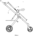
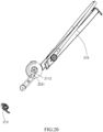
- the compact collapsible stroller (hereinafter referred to as "stroller") 1 of the present invention includes a collapsible main stroller frame 10 that can accommodate child seat frames 20 of various configurations (as shown in Fig. 1 ).
- the child seat frame 20 includes an upper frame 210, a lower frame 220, a child tray 230, and a seat mount 240 (as shown in Fig. 2 ).
- the seat mount 240 is configured to fix to the main stroller frame 10.
- the upper frame 210 and the lower frame 220 are pivotally connected to the seat mount 240 through an upper seat frame hub 211 and a lower seat frame hub 221.
- the child tray 230 is pivotally connected to the seat hub (seat mount) 240 through a child tray hub 231.
- the lower frame 220 has a second latch portion 224 and a lower frame locker 222.
- the child seat frame 20 has a seat mode and a cradle mode.
- One configuration for coupling the child seat frame 20 to the main stroller frame 10 is in a forward sitting position, which is the seat mode.
- the seat mode the upper frame 210 extends upward from the seat mount 240, specifically, obliquely extending backward and upward, and the lower frame 220 may extend downward from the seat mount 240, specifically, obliquely extending forward and downward.
- the upper frame 210 and the lower frame 220 are formed in a linear shape passing through the seat mount 240.
- the upper frame 210 and the lower frame 220 extend horizontally from the seat mount 240 to both sides thereof.
- the child seat frame 20 is converted from the position shown in Fig. 4 to a postion where the cradle is lying down.
- the user may manipulate the recline handle 223, which uses a cable to retract the spring-loaded lower frame locker 222 from a position engaging with the seat mount 240.
- This allows the entire child seat frame 20 to rotate to a horizontal position relative to the seat mount 240, and re-engages the spring-loaded lower frame locker 222 with the seat mount 240 to lock the child seat frame 20 in this position.
- the child seat frame 20 in addition to the reclining handle 223, the child seat frame 20 also includes a fold handle 213 for folding the child seat frame 20, as a part of the folding of the stroller.
- the fold handle 213 retracts the spring-biased upper frame locker 212 from its engagement position with the lower seat frame hub 221.
- the upper frame (i.e., upper seat frame) 210 can now rotate around the seat mount 240 relative to the lower frame (i.e., lower seat frame) 220.
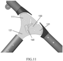
- a ramped surface 2111 in the upper seat frame hub 211 acts on a ramped surface 251 on the latch pin assembly 250 to press the latch pin assembly 250 into the seat mount 240, and separate the latch pin assembly 250 from the child tray hub 231, thereby releasing the child tray 230 to be able to pivot freely around the seat mount 240.
- a spiral control surface 2112 located in the upper seat frame hub 211 disengages the two lower seat frame hubs 221 from the seat mount 240 because it acts on a lower frame locker control post 2221. This allows the lower frame 220 to rotate around the seat mount 240 to a relatively vertical (upright) position with respect to the seat mount 240.
- the spiral control surface 2112 is formed to gradually move away from the center of the upper seat frame hub 211 from one side to the other, so that when the upper seat frame hub 211 rotates relative to the seat mount 240, the spiral control surface 2112 may abut against and push the lower frame locker control post 2221 to move away from the seat mount 240. Referring to Fig. 9 , this operation causes the upper frame 210, the lower frame 220 and the child tray 230 to fall parallel to one another and relatively vertical (upright) to the seat mount 240.
- the upper seat frame hub 211 includes a driving slot (as shown in Fig. 8 , the slot forming the spiral control surface 2112), and the lower frame locker 222 includes a guide post 2221 movably arranged in the driving slot.
- the driving slot is generally arc-shaped and has a certain angle range, for example, less than 180°.
- the spiral control surface 2112 is formed in the driving slot and is gradually away from the center of the upper seat frame hub from one side to the other side.
- the guide post 2221 abuts against the spiral control surface 2112, wherein when the upper seat frame hub 211 rotates, the spiral control surface 2112 can actuate the lower frame locker 222 so that the lower frame 220 engages with and disengages from the seat mount 240. That is, the rotation of the upper seat frame hub 211 may cause the lower frame 220 to engages with and disengages from the seat mount 240.
- a forward rotation (the direction from the left picture to the right picture shown in Fig. 8 ) of the upper seat frame hub 211 causes an unlocking state between the lower frame 220 and the seat mount 240.
- the spiral control surface 2112 may be formed to disengage the lower frame 220 from the seat mount 240 after the upper seat frame hub 211 rotates by one angle in the state where the lower frame 220 engages with the seat mount 240.
- the driving slot changes the slot width to drive the guide post 2221 arranged in the driving slot to produce displacement.
- the guide post 2221 When the upper seat frame 211 moves away from the lower seat frame 220, the guide post 2221 is located at a position where the slot width of the driving slot is larger (the left figure in Fig. 8 ). When the upper seat frame 211 gradually approaches the lower seat frame 220, the slot width of the driving slot is gradually reduced. At this time, the moving direction of the guide post 2221 is restricted to drive the guide post 2221 arranged in the driving slot to gradually move away from the center of the upper seat frame hub 211.
- the seat mount 240 may have a first latch portion 241. When the upper seat frame 211 and the lower seat frame 220 move close to each other, the guide post 2221 is located at a position where the slot width of the driving slot is smaller.
- the lower frame locker 222 is driven by the guide post 2221 to disengages from the first latch portion 241 so that the lower frame and the upper seat frame 211 pivots relative to the seat mount 240 together.
- the lower frame locker 222 may be actuated to be locked with and disengages from the first latch portion 241.
- the lower frame locker 222 disengages from the first latch portion 241, the lower frame 220 pivots with respect to the seat mount 240.
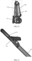
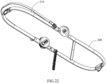
- the stroller main frame 10 includes a handle portion 110, a rear leg portion 120 and a front leg portion 130. Each part of the stroller main frame 10 is pivotally connected to a central frame hub 140.
- a frame latch 150 pivotally connected to a handle plate 111 engages with a locking pin 1211 on a rear leg plate 121 such that the stroller 1 is locked in the opening position.
- the frame latch 150 rotates so that the latch surface passes through the lock pin 1211 and disengages from the lock pin 1211, the handle plate 111 is allowed to rotate, and a front leg plate 131 is pulled by a link 160 to the folded position.
- the handle portion 110, the rear leg portion 120, and the front leg portion 130 are folded almost parallel to one anohter to obtain a compact folded size for easy transportation or storage of the main stroller frame 10 when the stroller is not in use.
- Fig. 12 the handle portion 110, the rear leg portion 120, and the front leg portion 130 are folded almost parallel to one anohter to obtain a compact folded size for easy transportation or storage of the main stroller frame 10 when the stroller is not in use.
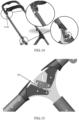
- the upper half of the handle portion 110 is locked by a spring biased locker 112 and thus cannot be rotated, the spring biased locker 112 is pulled to an unlocked state by a cable anchored in a main folding release housing.
- the upper handle portion 113 and the parent bracket rotates in the folding process to obtain a more compact folding size.
- the stroller 1 has a folding boundary (as shown by the dotted block in Fig. 12 ) in the folding process. When the stroller 1 is transformed between the unfolded state and the folded state, none of the parts of the stroller 1 can exceed beyond the folding boundary.
- the upper handle portion 113 is pivotally fixed to the handle hub 114.
- the spring biased locker 112 engages with the handle hub 114 so that the upper handle portion 113 cannot pivot relative to the handle hub 114.
- the spring biased locker 112 is actuated via a cable to disengage from the handle hub 114 so that the upper handle portion 113 pivots relative to the handle hub 114.
- the cable anchored on a circular barrel 1141 in the handle hub 114 and coupled to the frame latch 150 rotates with the upper handle portion 113, to actuate the frame latch 150 (an arrow in Fig. 15 shows a direction in which the frame latch 150 is actuated) and pivot it past the locking pin, and thus fold the handle portion 110 toward the closed position.
- Time for folding is controlled by an extended latch surface 151 of the frame latch 150.
- the extended latch surface 151 allows the frame latch 150 to engage with the locking pin 1211 until the upper handle portion 113 has rotated by a larger distance from its original position. When the extended latch surface 151 disengages from the locking pin 1211, the handle portion 110 may be folded toward the closed position.
- An upper link 116 is directly coupled to the seat frame hub (seat mount) 240 and is connected to the handle portion 110 at a pivot point 1151. Due to the downward folding movement of the handle portion 110, the upper link 116 is driven downward and the child seat hub (seat mount) 240 is pulled within a predetermined folding boundary. Referring to Figs. 17 and 17A , a basket frame is attached between a lower link 117 and a pivot point on the rear leg portion 120. Through the downward folding movement (pivoting movement) of the handle portion 110, the upper link 116 drives the lower link 117 in a downward movement, and further drives the basket frame downward and rotate it behind the rear leg portion 120. This allows the basket frame to be installed within the folding boundary while maximizing its size so as to achieve maximum storage capacity.
- the seat mount 240 gradually approaches the central frame hub 140, and finally overlaps or at least substantially overlaps in a transverse direction (perpendicular to the paper surface of Fig. 16A ).
- the handle portion 110, the rear leg portion 120, and the front leg portion 130 vertically extend substantially downward from the central frame hub 140, and the upper frame 210, the lower frame 220, and the child tray 230 vertically extend substantially downward from the seat mount 240, so that the stroller 1 in the folded state occupies the minimum space.
Landscapes
- Engineering & Computer Science (AREA)
- Chemical & Material Sciences (AREA)
- Combustion & Propulsion (AREA)
- Transportation (AREA)
- Mechanical Engineering (AREA)
- Carriages For Children, Sleds, And Other Hand-Operated Vehicles (AREA)
Claims (15)
- Kindersitzrahmen (20), umfassend:eine Sitzhalterung (240), die eingerichtet ist, an einem Kinderwagenhauptrahmen befestigt zu werden, und einen ersten Verriegelungsabschnitt (241) aufweist;einen unteren Rahmen (220), der eine untere Sitzrahmennabe (221) aufweist und schwenkbar mit der Sitzhalterung gekoppelt ist, wobei der untere Rahmen einen zweiten Verriegelungsabschnitt (224) und eine untere Rahmenverriegelung (222) aufweist, wobei die untere Rahmenverriegelung (222) betrieben wird, um mit dem ersten Verriegelungsabschnitt einzugreifen und sich von diesem zu lösen, und wenn sich die untere Rahmenverriegelung von dem ersten Verriegelungsabschnitt löst, schwenkt der untere Rahmen relativ zu der Sitzhalterung; undeinen oberen Rahmen (210), der schwenkbar mit der Sitzhalterung (240) und dem unteren Rahmen (220) gekoppelt ist,dadurch gekennzeichnet, dass der obere Rahmen eine obere Rahmenverriegelung (212) aufweist, wobei die obere Rahmenverriegelung betrieben wird, um mit dem zweiten Verriegelungsabschnitt einzugreifen und sich von diesem zu lösen, und wenn sich die obere Rahmenverriegelung von der unteren Sitzrahmennabe löst, schwenkt der obere Rahmen relativ zu der unteren Sitzrahmennabe;wobei die obere Rahmenverriegelung (212) mit dem zweiten Verriegelungsabschnitt eingreift, wenn der untere Rahmen relativ zu der Sitzhalterung schwenkt.
- Kindersitzrahmen (20) nach Anspruch 1, dadurch gekennzeichnet, dass der Kindersitzrahmen ferner eine Kinderablage (230) umfasst, die eine Kinderablagenabe (231) aufweist und schwenkbar mit der Sitzhalterung (240), dem oberen Rahmen und dem unteren Rahmen (220) gekoppelt ist.
- Kindersitzrahmen (20) nach Anspruch 2, dadurch gekennzeichnet, dass der Kindersitzrahmen ferner eine Verriegelungsstiftanordnung (250) umfasst, die in der Sitzhalterung befestigt ist und mit der Kinderablagenabe eingreift oder sich von dieser löst, wobei die Kinderablage nicht relativ zu der Verriegelungsstiftanordnung schwenkt, wenn die Verriegelungsstiftanordnung mit der Kinderablagenabe eingreift, und die Kinderablage relativ zu der Verriegelungsstiftanordnung schwenkt, wenn sich die Verriegelungsstiftanordnung von der Kinderablagenabe löst.
- Kindersitzrahmen (20) nach Anspruch 3, dadurch gekennzeichnet, dass der obere Rahmen eine obere Sitzrahmennabe aufweist, eine angeschrägte Fläche (251) auf einer Seite der Verriegelungsstiftanordnung ausgebildet ist und eine andere angeschrägte Fläche (2111) auf einer Seite der oberen Sitzrahmennabe ausgebildet ist und die eine angeschrägte Fläche mit der anderen angeschrägten Fläche derart zusammenwirkt, dass die Verriegelungsstiftanordnung mit der Kinderablagenabe eingreift oder sich von dieser löst.
- Kindersitzrahmen (20) nach einem der vorhergehenden Ansprüche, dadurch gekennzeichnet, dass der Kindersitzrahmen einen Sitzmodus und einen Wiegemodus aufweist, wobei in dem Sitzmodus der obere Rahmen in Richtung einer oberen Seite der Sitzhalterung geneigt ist, der untere Rahmen in Richtung einer unteren Seite der Sitzhalterung geneigt ist und der obere Rahmen und der untere Rahmen als eine gerade Linie ausgebildet sind; und in dem Wiegemodus der obere Rahmen und der untere Rahmen als eine horizontale gerade Linie ausgebildet sind.
- Kindersitzrahmen (20) nach einem der vorhergehenden Ansprüche, dadurch gekennzeichnet, dass ein Neigungsgriff (223) an dem unteren Rahmen vorgesehen ist und der Neigungsgriff mit der unteren Rahmenverriegelung verbunden ist, so dass sich die untere Rahmenverriegelung von dem ersten Verriegelungsabschnitt durch Betätigen des Neigungsgriffs löst.
- Kindersitzrahmen (20) nach einem der vorhergehenden Ansprüche, dadurch gekennzeichnet, dass ein Faltgriff (213) an dem oberen Rahmen vorgesehen ist und der Faltgriff mit der oberen Rahmenverriegelung verbunden ist, so dass sich die obere Rahmenverriegelung von dem zweiten Verriegelungsabschnitt durch Betätigen des Faltgriffs löst.
- Kindersitzrahmen (20) nach einem der vorhergehenden Ansprüche, dadurch gekennzeichnet, dass der obere Rahmen eine obere Sitzrahmennabe aufweist, ein Antriebsschlitz an der oberen Sitzrahmennabe ausgebildet ist und ein Führungspfosten (2221) an der unteren Rahmenverriegelung ausgebildet ist, um zu ermöglichen, dass die untere Rahmenverriegelung beweglich in dem Antriebsschlitz angeordnet ist.
- Kindersitzrahmen (20) nach Anspruch 8, dadurch gekennzeichnet, dass eine spiralförmige Steuerfläche (2112) in dem Antriebsschlitz ausgebildet ist und sich die spiralförmige Steuerfläche von einer Seite zu der anderen Seite graduell von einer Mitte der oberen Sitzrahmennabe weg bewegt.
- Kindersitzrahmen (20) nach Anspruch 9, dadurch gekennzeichnet, dass der Führungspfosten (2221) an der spiralförmigen Steuerfläche anliegt und, wenn sich die obere Sitzrahmennabe dreht, die spiralförmige Steuerfläche die untere Rahmenverriegelung derart antreibt, dass der untere Rahmen mit der Sitzhalterung eingreift und sich von dieser löst.
- Kindersitzrahmen (20) nach Anspruch 9 oder 10, dadurch gekennzeichnet, dass die spiralförmige Steuerfläche bewirkt, dass in einem Zustand, in dem der untere Rahmen mit der Sitzhalterung eingreift, sich der untere Rahmen von der Sitzhalterung löst, nachdem sich die obere Sitzrahmennabe um einen Winkel dreht.
- Kindersitzrahmen (20) nach einem der Ansprüche 8 bis 11, dadurch gekennzeichnet, dass der Antriebsschlitz den Führungspfosten (2221), der in dem Antriebsschlitz angeordnet ist, antreibt, um eine Verschiebung durch Ändern einer Schlitzbreite zu erzeugen;
wobei, optional, wenn sich der obere Sitzrahmen von dem unteren Sitzrahmen weg bewegt, sich der Führungspfosten (2221) an einer Position befindet, an der die Schlitzbreite des Antriebsschlitzes größer ist, und wenn sich der obere Sitzrahmen graduell dem unteren Sitzrahmen nähert, die Schlitzbreite des Antriebsschlitzes graduell verringert wird, um den Führungspfosten (2221), der in dem Antriebsschlitz angeordnet ist, anzutreiben, um sich graduell von einer Mitte der oberen Sitzrahmennabe weg zu bewegen. - Kindersitzrahmen (20) nach einem der vorhergehenden Ansprüche, dadurch gekennzeichnet, dass der obere Rahmen, der untere Rahmen und die Kinderablage relativ zu der Sitzhalterung schwenken, um parallel zueinander und in einer vertikalen Position zu sein.
- Kindersitzrahmen (20) nach einem der vorhergehenden Ansprüche, dadurch gekennzeichnet, dass die untere Rahmenverriegelung mit einem elastischen Element versehen ist, um dazu zu neigen, die untere Rahmenverriegelung zurück zu dem ersten Verriegelungsabschnitt zurückzuführen, und die obere Rahmenverriegelung mit einem anderen elastischen Element versehen ist, um dazu zu neigen, die obere Rahmenverriegelung zurück zu dem zweiten Verriegelungsabschnitt zurückzuführen.
- Kompakter zusammenklappbarer Kinderwagen (1), dadurch gekennzeichnet, dass der kompakte zusammenklappbare Kinderwagen einen Kinderwagenhauptrahmen (10) und einen Kindersitzrahmennach einem der Ansprüche 1-14 umfasst, der mit dem Kinderwagenhauptrahmen gekoppelt ist.
Priority Applications (1)
| Application Number | Priority Date | Filing Date | Title |
|---|---|---|---|
| EP25161019.2A EP4538147A3 (de) | 2019-11-27 | 2020-11-27 | Kindersitzrahmen und kompakter zusammenklappbarer kinderwagen |
Applications Claiming Priority (2)
| Application Number | Priority Date | Filing Date | Title |
|---|---|---|---|
| US201962941303P | 2019-11-27 | 2019-11-27 | |
| PCT/IB2020/061218 WO2021105945A1 (zh) | 2019-11-27 | 2020-11-27 | 儿童座椅框架和紧凑型可折叠婴儿车 |
Related Child Applications (2)
| Application Number | Title | Priority Date | Filing Date |
|---|---|---|---|
| EP25161019.2A Division EP4538147A3 (de) | 2019-11-27 | 2020-11-27 | Kindersitzrahmen und kompakter zusammenklappbarer kinderwagen |
| EP25161019.2A Division-Into EP4538147A3 (de) | 2019-11-27 | 2020-11-27 | Kindersitzrahmen und kompakter zusammenklappbarer kinderwagen |
Publications (2)
| Publication Number | Publication Date |
|---|---|
| EP4067207A1 EP4067207A1 (de) | 2022-10-05 |
| EP4067207B1 true EP4067207B1 (de) | 2025-04-09 |
Family
ID=73598873
Family Applications (5)
| Application Number | Title | Priority Date | Filing Date |
|---|---|---|---|
| EP20815785.9A Active EP4065449B1 (de) | 2019-11-27 | 2020-11-26 | Kinderwagenvorrichtung |
| EP24159170.0A Pending EP4371850A1 (de) | 2019-11-27 | 2020-11-26 | Kinderwagenvorrichtung |
| EP25161019.2A Pending EP4538147A3 (de) | 2019-11-27 | 2020-11-27 | Kindersitzrahmen und kompakter zusammenklappbarer kinderwagen |
| EP20839141.7A Pending EP4067206A1 (de) | 2019-11-27 | 2020-11-27 | Kompakter faltbarer kinderwagen |
| EP20841758.4A Active EP4067207B1 (de) | 2019-11-27 | 2020-11-27 | Kindersitzrahmen und kompakter faltbarer kinderwagen |
Family Applications Before (4)
| Application Number | Title | Priority Date | Filing Date |
|---|---|---|---|
| EP20815785.9A Active EP4065449B1 (de) | 2019-11-27 | 2020-11-26 | Kinderwagenvorrichtung |
| EP24159170.0A Pending EP4371850A1 (de) | 2019-11-27 | 2020-11-26 | Kinderwagenvorrichtung |
| EP25161019.2A Pending EP4538147A3 (de) | 2019-11-27 | 2020-11-27 | Kindersitzrahmen und kompakter zusammenklappbarer kinderwagen |
| EP20839141.7A Pending EP4067206A1 (de) | 2019-11-27 | 2020-11-27 | Kompakter faltbarer kinderwagen |
Country Status (10)
| Country | Link |
|---|---|
| US (4) | US12246768B2 (de) |
| EP (5) | EP4065449B1 (de) |
| JP (3) | JP7668275B2 (de) |
| KR (2) | KR20250114560A (de) |
| CN (2) | CN112849253A (de) |
| AU (1) | AU2020391923B2 (de) |
| CA (3) | CA3154263A1 (de) |
| ES (2) | ES2983237T3 (de) |
| TW (5) | TWI862950B (de) |
| WO (3) | WO2021105286A1 (de) |
Families Citing this family (4)
| Publication number | Priority date | Publication date | Assignee | Title |
|---|---|---|---|---|
| CN116552618A (zh) * | 2019-10-17 | 2023-08-08 | 明门瑞士股份有限公司 | 婴儿车及其同步收合机构 |
| TWI862950B (zh) * | 2019-11-27 | 2024-11-21 | 瑞士商明門瑞士股份有限公司 | 嬰幼兒推車 |
| TWI857348B (zh) * | 2021-09-16 | 2024-10-01 | 瑞士商明門瑞士股份有限公司 | 嬰兒載具 |
| CN218106691U (zh) * | 2022-05-20 | 2022-12-23 | 宁波稳泰运动器材有限公司 | 一种高尔夫球车 |
Citations (1)
| Publication number | Priority date | Publication date | Assignee | Title |
|---|---|---|---|---|
| GB2496225A (en) * | 2011-11-07 | 2013-05-08 | Unique Product & Design Co Ltd | A stroller with a folding and rotatable seat |
Family Cites Families (92)
| Publication number | Priority date | Publication date | Assignee | Title |
|---|---|---|---|---|
| US3459435A (en) | 1967-08-21 | 1969-08-05 | Herschal F Garhan | Baby strollers |
| US3556546A (en) | 1967-08-21 | 1971-01-19 | Herschall F Garhan | Baby strollers |
| IT7420617U1 (it) | 1974-01-25 | 1975-07-25 | Perego Pines Spa | Passeggino per bambini, facilmente ripiegabile e trasportabile sul braccio |
| US6102431A (en) | 1998-06-01 | 2000-08-15 | Hood Technology Corporation | Collapsible baby stroller and releasable locking and folding mechanism therefor |
| US6523853B1 (en) | 2001-11-05 | 2003-02-25 | Kenny Cheng | Safe folding device for a foldable stroller |
| DE602005025994D1 (de) * | 2004-04-13 | 2011-03-03 | Graco Childrens Prod Inc | Kinderwagen mit beweglicher korbanordnung |
| GB2419520B (en) * | 2004-09-28 | 2008-04-09 | Armon Ltd | Convertible seat for a baby buggy |
| GB0422967D0 (en) | 2004-10-15 | 2004-11-17 | Derek Bull Associates Ltd | Folding wheeled chair |
| US7255206B1 (en) | 2005-03-05 | 2007-08-14 | Hackbarth Christina L | Shopping cart brake |
| TWM288269U (en) * | 2005-09-29 | 2006-03-01 | Link Treasure Ltd | One-hand controlled seat inclination structure for baby trolley |
| TWM295071U (en) | 2006-01-18 | 2006-08-01 | Link Treasure Ltd | Joint structure for baby stroller |
| US7267359B1 (en) * | 2006-06-08 | 2007-09-11 | Link Treasure Limited | Collapsible stroller frame |
| DE202006012430U1 (de) | 2006-08-11 | 2006-10-12 | Hauck Gmbh & Co. Kg | Fahrgestell für einen Kinderwagen, eine Kinderkarre o.dgl. |
| US8485546B2 (en) | 2006-09-08 | 2013-07-16 | Lerado (Zhong Shan) Industrial Co., Ltd. | Foldable baby stroller frame |
| TWM325960U (en) | 2006-09-29 | 2008-01-21 | Golden Point Marketing Ltd | Folding control mechanism for baby stroller |
| US8087689B2 (en) | 2008-07-31 | 2012-01-03 | Cosco Management, Inc. | Compact collapsible stroller |
| GB0818605D0 (en) * | 2008-10-10 | 2008-11-19 | Scs London Ltd | Apparatus and method |
| US8474854B2 (en) | 2009-03-24 | 2013-07-02 | Graco Children's Products Inc. | Foldable stroller and fold interlock mechanism |
| US8764048B1 (en) | 2009-01-08 | 2014-07-01 | Graco Children's Products Inc. | Foldable, removable, reversible stroller seat |
| GB2468596B (en) | 2009-03-13 | 2012-01-04 | Graco Childrens Prod Inc | Stroller and seat assembly |
| US8714581B2 (en) * | 2010-01-25 | 2014-05-06 | Cosco Management, Inc. | Compact foldable stroller |
| CN201769848U (zh) | 2010-05-20 | 2011-03-23 | 刘修平 | 单手收合的婴儿车 |
| KR101793220B1 (ko) * | 2010-09-01 | 2017-11-02 | 브리택스 차일드케어 프로프라이어터리 리미티드 | 개선된 접이식 유모차 |
| US8657326B2 (en) | 2011-04-26 | 2014-02-25 | Cosco Management, Inc. | Stroller with convertible child-support system |
| US8596669B2 (en) | 2011-11-07 | 2013-12-03 | Unique Product & Design Co., Ltd. | Baby stroller |
| US20130113185A1 (en) * | 2011-11-07 | 2013-05-09 | Dynamic Brands, Llc | Baby stroller |
| US9050993B2 (en) * | 2012-02-02 | 2015-06-09 | Graco Children's Products Inc. | Foldable stroller and automatic folding tray for same |
| CN103318242B (zh) | 2012-03-19 | 2015-11-25 | 珠海优力创工贸有限公司 | 具有换向座位的可收合婴儿车 |
| DE102013005495B4 (de) * | 2012-03-29 | 2022-05-05 | Wonderland Nurserygoods Company Limited | Kinderwagen und Kinderwagengestell |
| CN103373382B (zh) | 2012-04-20 | 2015-11-25 | 珠海优力创工贸有限公司 | 换向座位和具有换向座位的可收合婴儿车 |
| NO335333B1 (no) * | 2012-09-19 | 2014-11-17 | Stokke As | Barnevogn |
| US9399477B2 (en) | 2012-12-27 | 2016-07-26 | Kolcraft Enterprises, Inc. | Strollers with removable child supports and related methods |
| US8882134B2 (en) | 2013-01-07 | 2014-11-11 | Kolcraft Enterprises, Inc. | Maneuverable strollers |
| EP2832624A4 (de) | 2013-01-28 | 2016-02-10 | Unitron Entpr Zhuhai Co Ltd | Klappgelenk für kinderwagen |
| US9221487B2 (en) | 2013-04-30 | 2015-12-29 | Graco Children's Products Inc. | Convertible stroller seat |
| CN203318470U (zh) * | 2013-05-09 | 2013-12-04 | 中山市隆成日用制品有限公司 | 童车骨架关节 |
| CN203427850U (zh) * | 2013-07-05 | 2014-02-12 | 中山市隆成日用制品有限公司 | 婴儿车收折关节的释放机构 |
| US9108659B2 (en) * | 2013-08-07 | 2015-08-18 | Recaro Child Safety Llc | Stroller with selectively hidden adapters |
| CN203558113U (zh) | 2013-10-17 | 2014-04-23 | 欧仕儿童用品(福建)有限公司 | 快速收折的儿童车架 |
| US20150183450A1 (en) | 2013-12-31 | 2015-07-02 | Way-Hong Chen | Baby Stroller Shopping Cart |
| US9463822B2 (en) | 2014-01-10 | 2016-10-11 | Dorel Juvenile Group, Inc. | Stroller |
| CN203996350U (zh) | 2014-01-10 | 2014-12-10 | 克斯克管理公司 | 可收折的推车 |
| CN204641848U (zh) | 2014-04-10 | 2015-09-16 | 明门(中国)幼童用品有限公司 | 婴儿车站立装置及婴儿车 |
| CN204137084U (zh) | 2014-05-29 | 2015-02-04 | 珠海优力创工贸有限公司 | 用于推车的铰链和可折叠推车 |
| US9545940B2 (en) * | 2014-06-30 | 2017-01-17 | Wonderland Nurserygoods Company Limited | Infant stroller apparatus |
| CN106573636B (zh) | 2014-07-23 | 2019-08-23 | 恩德普罗有限责任公司 | 儿童车 |
| US9517787B2 (en) * | 2014-08-14 | 2016-12-13 | Baby Jogger Llc | Baby stroller |
| CN105564489B (zh) * | 2014-10-10 | 2018-04-13 | 明门香港股份有限公司 | 婴儿承载装置及婴儿推车 |
| CN105984481B (zh) * | 2015-02-11 | 2018-05-04 | 明门香港股份有限公司 | 婴儿车架 |
| CN106184331B (zh) | 2015-04-29 | 2018-07-06 | 珠海阳光儿童用品有限公司 | 婴儿车座椅架和婴儿车 |
| US9908551B2 (en) | 2015-09-02 | 2018-03-06 | Artsana USA, Inc | Travel stroller folding and latch mechanism |
| CN106741091B (zh) | 2015-11-23 | 2019-04-02 | 明门香港股份有限公司 | 婴儿车 |
| US9796405B2 (en) | 2015-11-23 | 2017-10-24 | Wonderland Nurserygoods Company Limited | Infant stroller apparatus |
| CN105539557B (zh) | 2016-02-03 | 2018-08-10 | 广东乐美达集团有限公司 | 一种可联动折叠的童车 |
| ES2901525T3 (es) | 2016-02-03 | 2022-03-22 | Wonderland Switzerland Ag | Aparato de cochecito de niños que tiene una estructura extensible |
| CN107235062B (zh) * | 2016-03-29 | 2019-07-09 | 明门香港股份有限公司 | 婴儿车架 |
| CN107284506B (zh) * | 2016-04-13 | 2019-11-19 | 明门香港股份有限公司 | 折叠座椅组及婴儿车 |
| GB2571439B (en) * | 2016-04-29 | 2020-04-01 | Wonderland Switzerland Ag | Child stroller apparatus |
| US10239550B2 (en) * | 2016-04-29 | 2019-03-26 | Wonderland Switzerland Ag | Child stroller apparatus |
| US20200172142A1 (en) | 2016-07-12 | 2020-06-04 | Dynamic Motion, Llc | Z-foldable stroller and accessories |
| AU2017295309A1 (en) | 2016-07-12 | 2019-02-07 | Dongguan Always Shine Daily Article Co., Ltd | Z-foldable stroller and accessories |
| CN206384007U (zh) | 2016-11-22 | 2017-08-08 | 明门瑞士股份有限公司 | 可收合式婴儿车 |
| FR3059968B1 (fr) * | 2016-12-13 | 2019-05-24 | Dorel France | Support convertible entre une position allongee et au moins une position assise pour poussette pour enfant, et poussette correspondante |
| CN108275194B (zh) * | 2017-01-06 | 2021-06-08 | 明门瑞士股份有限公司 | 具有餐盘的婴儿车车架 |
| US9962011B1 (en) * | 2017-01-27 | 2018-05-08 | Kolcraft Enterprises, Inc. | Recline assemblies for stroller seats |
| EP3363711A1 (de) * | 2017-02-14 | 2018-08-22 | Dorel France | Kinderwagen, der einen abnehmbaren zusatzsitz umfasst, und entsprechender zusatzsitz |
| CA3002926C (en) * | 2017-04-26 | 2021-06-01 | Wonderland Switzerland Ag | Child stroller apparatus |
| CN108860279B (zh) * | 2017-05-15 | 2021-01-29 | 明门瑞士股份有限公司 | 婴儿车及其收折机构 |
| CN206885123U (zh) | 2017-05-19 | 2018-01-16 | 东莞硕仕儿童用品有限公司 | 一种折叠婴儿推车 |
| CN107264600A (zh) * | 2017-06-01 | 2017-10-20 | 好孩子儿童用品有限公司 | 一种儿童推车 |
| US10858030B2 (en) * | 2017-07-18 | 2020-12-08 | Wonderland Switzerland Ag | Baby carrier with a convertible seat frame |
| CN207360393U (zh) | 2017-08-31 | 2018-05-15 | 昆山威凯儿童用品有限公司 | 一种可折叠的婴儿推车 |
| US10449987B2 (en) | 2018-01-17 | 2019-10-22 | Evenflo Company, Inc. | Tandem stroller with sliding carriage |
| US10882546B2 (en) | 2018-03-07 | 2021-01-05 | Zhongshan Kingmoon Children Products Co. Ltd. | Stroller |
| US10766517B2 (en) * | 2018-03-16 | 2020-09-08 | Strova, Inc. | Stroller assembly |
| KR101894460B1 (ko) * | 2018-04-10 | 2018-09-04 | 김미진 | 사용 편의성을 향상시킨 유모차 |
| US11091185B2 (en) | 2018-05-21 | 2021-08-17 | Wonderland Switzerland Ag | Stroller |
| CN209079968U (zh) * | 2018-09-19 | 2019-07-09 | 明门瑞士股份有限公司 | 座椅角度调整机构 |
| CN209208837U (zh) * | 2018-10-30 | 2019-08-06 | 明门(中国)幼童用品有限公司 | 收折机构及其幼儿载具 |
| CN111409686B (zh) * | 2019-01-08 | 2022-12-06 | 明门瑞士股份有限公司 | 后轮可收合的车架 |
| CN209535175U (zh) * | 2019-01-15 | 2019-10-25 | 徐江林 | 一种折叠童车 |
| CN115042851B (zh) | 2019-01-29 | 2024-11-26 | 明门(中国)幼童用品有限公司 | 枢转座机构及包含该枢转座机构的儿童推车 |
| CN115571212A (zh) * | 2019-01-29 | 2023-01-06 | 明门瑞士股份有限公司 | 载体转换机构 |
| US11325630B2 (en) * | 2019-05-07 | 2022-05-10 | Wonderland Switzerland Ag | Multi child stroller |
| US11225279B2 (en) | 2019-05-09 | 2022-01-18 | Wonderland Switzerland Ag | Child seat and foldable stroller thereof |
| US11390311B2 (en) | 2019-05-09 | 2022-07-19 | Wonderland Switzerland Ag | Child stroller apparatus |
| CN116118844A (zh) | 2019-09-26 | 2023-05-16 | 明门瑞士股份有限公司 | 扶手收合机构及具有该机构的婴儿车 |
| CN116552618A (zh) | 2019-10-17 | 2023-08-08 | 明门瑞士股份有限公司 | 婴儿车及其同步收合机构 |
| US11136055B2 (en) | 2019-11-04 | 2021-10-05 | Dynamic Motion, Llc | Foldable stroller |
| TWI862950B (zh) | 2019-11-27 | 2024-11-21 | 瑞士商明門瑞士股份有限公司 | 嬰幼兒推車 |
| KR20230058015A (ko) * | 2020-06-01 | 2023-05-02 | 원더랜드 스위처랜드 아게 | 컴팩트한 접이식 유모차 |
| CN120886901A (zh) | 2021-11-10 | 2025-11-04 | 明门瑞士股份有限公司 | 婴儿载具 |
-
2020
- 2020-11-26 TW TW111126260A patent/TWI862950B/zh active
- 2020-11-26 KR KR1020257024271A patent/KR20250114560A/ko active Pending
- 2020-11-26 KR KR1020227014507A patent/KR102837648B1/ko active Active
- 2020-11-26 TW TW113139461A patent/TWI903813B/zh active
- 2020-11-26 ES ES20815785T patent/ES2983237T3/es active Active
- 2020-11-26 EP EP20815785.9A patent/EP4065449B1/de active Active
- 2020-11-26 CA CA3154263A patent/CA3154263A1/en active Pending
- 2020-11-26 TW TW109141596A patent/TWI774139B/zh active
- 2020-11-26 WO PCT/EP2020/083512 patent/WO2021105286A1/en not_active Ceased
- 2020-11-26 JP JP2022529890A patent/JP7668275B2/ja active Active
- 2020-11-26 EP EP24159170.0A patent/EP4371850A1/de active Pending
- 2020-11-26 AU AU2020391923A patent/AU2020391923B2/en active Active
- 2020-11-27 EP EP25161019.2A patent/EP4538147A3/de active Pending
- 2020-11-27 US US17/756,454 patent/US12246768B2/en active Active
- 2020-11-27 CN CN202011363386.4A patent/CN112849253A/zh active Pending
- 2020-11-27 WO PCT/IB2020/061218 patent/WO2021105945A1/zh not_active Ceased
- 2020-11-27 US US17/756,575 patent/US12179826B2/en active Active
- 2020-11-27 EP EP20839141.7A patent/EP4067206A1/de active Pending
- 2020-11-27 WO PCT/IB2020/061216 patent/WO2021105944A1/zh not_active Ceased
- 2020-11-27 EP EP20841758.4A patent/EP4067207B1/de active Active
- 2020-11-27 CA CA3159712A patent/CA3159712A1/en active Pending
- 2020-11-27 TW TW109141902A patent/TWI759983B/zh active
- 2020-11-27 ES ES20841758T patent/ES3040718T3/es active Active
- 2020-11-27 CA CA3159312A patent/CA3159312A1/en active Pending
- 2020-11-27 CN CN202011358282.4A patent/CN112849252A/zh active Pending
- 2020-11-27 TW TW109141883A patent/TWI759982B/zh active
-
2024
- 2024-07-05 JP JP2024108937A patent/JP7791255B2/ja active Active
- 2024-10-24 US US18/926,217 patent/US20250050933A1/en active Pending
-
2025
- 2025-01-28 US US19/038,869 patent/US20250269893A1/en active Pending
- 2025-10-22 JP JP2025177812A patent/JP2026021366A/ja active Pending
Patent Citations (1)
| Publication number | Priority date | Publication date | Assignee | Title |
|---|---|---|---|---|
| GB2496225A (en) * | 2011-11-07 | 2013-05-08 | Unique Product & Design Co Ltd | A stroller with a folding and rotatable seat |
Also Published As
Similar Documents
| Publication | Publication Date | Title |
|---|---|---|
| EP4067207B1 (de) | Kindersitzrahmen und kompakter faltbarer kinderwagen | |
| US11731681B2 (en) | Child stroller apparatus | |
| US20240190496A1 (en) | Child stroller apparatus | |
| US11944211B2 (en) | Child seat | |
| US20230234628A1 (en) | Child stroller apparatus | |
| US8936267B2 (en) | Collapsible child carrier apparatus | |
| US20130207369A1 (en) | Foldable Stroller and Automatic Folding Tray for Same | |
| EP2418139A2 (de) | Kinderwagen mit Gelenkstruktur | |
| GB2476391A (en) | A collapsible perambulator with hinges having latching members | |
| TWI891006B (zh) | 限位裝置及兒童載具 |
Legal Events
| Date | Code | Title | Description |
|---|---|---|---|
| STAA | Information on the status of an ep patent application or granted ep patent |
Free format text: STATUS: UNKNOWN |
|
| STAA | Information on the status of an ep patent application or granted ep patent |
Free format text: STATUS: THE INTERNATIONAL PUBLICATION HAS BEEN MADE |
|
| PUAI | Public reference made under article 153(3) epc to a published international application that has entered the european phase |
Free format text: ORIGINAL CODE: 0009012 |
|
| STAA | Information on the status of an ep patent application or granted ep patent |
Free format text: STATUS: REQUEST FOR EXAMINATION WAS MADE |
|
| 17P | Request for examination filed |
Effective date: 20220622 |
|
| AK | Designated contracting states |
Kind code of ref document: A1 Designated state(s): AL AT BE BG CH CY CZ DE DK EE ES FI FR GB GR HR HU IE IS IT LI LT LU LV MC MK MT NL NO PL PT RO RS SE SI SK SM TR |
|
| DAV | Request for validation of the european patent (deleted) | ||
| DAX | Request for extension of the european patent (deleted) | ||
| STAA | Information on the status of an ep patent application or granted ep patent |
Free format text: STATUS: EXAMINATION IS IN PROGRESS |
|
| 17Q | First examination report despatched |
Effective date: 20230619 |
|
| GRAP | Despatch of communication of intention to grant a patent |
Free format text: ORIGINAL CODE: EPIDOSNIGR1 |
|
| STAA | Information on the status of an ep patent application or granted ep patent |
Free format text: STATUS: GRANT OF PATENT IS INTENDED |
|
| INTG | Intention to grant announced |
Effective date: 20241028 |
|
| P01 | Opt-out of the competence of the unified patent court (upc) registered |
Free format text: CASE NUMBER: APP_67031/2024 Effective date: 20241218 |
|
| GRAS | Grant fee paid |
Free format text: ORIGINAL CODE: EPIDOSNIGR3 |
|
| GRAA | (expected) grant |
Free format text: ORIGINAL CODE: 0009210 |
|
| STAA | Information on the status of an ep patent application or granted ep patent |
Free format text: STATUS: THE PATENT HAS BEEN GRANTED |
|
| AK | Designated contracting states |
Kind code of ref document: B1 Designated state(s): AL AT BE BG CH CY CZ DE DK EE ES FI FR GB GR HR HU IE IS IT LI LT LU LV MC MK MT NL NO PL PT RO RS SE SI SK SM TR |
|
| REG | Reference to a national code |
Ref country code: GB Ref legal event code: FG4D |
|
| REG | Reference to a national code |
Ref country code: CH Ref legal event code: EP |
|
| REG | Reference to a national code |
Ref country code: DE Ref legal event code: R096 Ref document number: 602020049249 Country of ref document: DE |
|
| REG | Reference to a national code |
Ref country code: IE Ref legal event code: FG4D |
|
| REG | Reference to a national code |
Ref country code: NL Ref legal event code: FP |
|
| REG | Reference to a national code |
Ref country code: AT Ref legal event code: MK05 Ref document number: 1783308 Country of ref document: AT Kind code of ref document: T Effective date: 20250409 |
|
| PG25 | Lapsed in a contracting state [announced via postgrant information from national office to epo] |
Ref country code: PT Free format text: LAPSE BECAUSE OF FAILURE TO SUBMIT A TRANSLATION OF THE DESCRIPTION OR TO PAY THE FEE WITHIN THE PRESCRIBED TIME-LIMIT Effective date: 20250811 Ref country code: FI Free format text: LAPSE BECAUSE OF FAILURE TO SUBMIT A TRANSLATION OF THE DESCRIPTION OR TO PAY THE FEE WITHIN THE PRESCRIBED TIME-LIMIT Effective date: 20250409 |
|
| REG | Reference to a national code |
Ref country code: LT Ref legal event code: MG9D |
|
| PG25 | Lapsed in a contracting state [announced via postgrant information from national office to epo] |
Ref country code: GR Free format text: LAPSE BECAUSE OF FAILURE TO SUBMIT A TRANSLATION OF THE DESCRIPTION OR TO PAY THE FEE WITHIN THE PRESCRIBED TIME-LIMIT Effective date: 20250710 Ref country code: NO Free format text: LAPSE BECAUSE OF FAILURE TO SUBMIT A TRANSLATION OF THE DESCRIPTION OR TO PAY THE FEE WITHIN THE PRESCRIBED TIME-LIMIT Effective date: 20250709 |
|
| PG25 | Lapsed in a contracting state [announced via postgrant information from national office to epo] |
Ref country code: PL Free format text: LAPSE BECAUSE OF FAILURE TO SUBMIT A TRANSLATION OF THE DESCRIPTION OR TO PAY THE FEE WITHIN THE PRESCRIBED TIME-LIMIT Effective date: 20250409 |
|
| PG25 | Lapsed in a contracting state [announced via postgrant information from national office to epo] |
Ref country code: BG Free format text: LAPSE BECAUSE OF FAILURE TO SUBMIT A TRANSLATION OF THE DESCRIPTION OR TO PAY THE FEE WITHIN THE PRESCRIBED TIME-LIMIT Effective date: 20250409 |
|
| PG25 | Lapsed in a contracting state [announced via postgrant information from national office to epo] |
Ref country code: HR Free format text: LAPSE BECAUSE OF FAILURE TO SUBMIT A TRANSLATION OF THE DESCRIPTION OR TO PAY THE FEE WITHIN THE PRESCRIBED TIME-LIMIT Effective date: 20250409 |
|
| PG25 | Lapsed in a contracting state [announced via postgrant information from national office to epo] |
Ref country code: AT Free format text: LAPSE BECAUSE OF FAILURE TO SUBMIT A TRANSLATION OF THE DESCRIPTION OR TO PAY THE FEE WITHIN THE PRESCRIBED TIME-LIMIT Effective date: 20250409 |
|
| PG25 | Lapsed in a contracting state [announced via postgrant information from national office to epo] |
Ref country code: RS Free format text: LAPSE BECAUSE OF FAILURE TO SUBMIT A TRANSLATION OF THE DESCRIPTION OR TO PAY THE FEE WITHIN THE PRESCRIBED TIME-LIMIT Effective date: 20250709 |
|
| PG25 | Lapsed in a contracting state [announced via postgrant information from national office to epo] |
Ref country code: IS Free format text: LAPSE BECAUSE OF FAILURE TO SUBMIT A TRANSLATION OF THE DESCRIPTION OR TO PAY THE FEE WITHIN THE PRESCRIBED TIME-LIMIT Effective date: 20250809 |
|
| PG25 | Lapsed in a contracting state [announced via postgrant information from national office to epo] |
Ref country code: LV Free format text: LAPSE BECAUSE OF FAILURE TO SUBMIT A TRANSLATION OF THE DESCRIPTION OR TO PAY THE FEE WITHIN THE PRESCRIBED TIME-LIMIT Effective date: 20250409 |
|
| REG | Reference to a national code |
Ref country code: ES Ref legal event code: FG2A Ref document number: 3040718 Country of ref document: ES Kind code of ref document: T3 Effective date: 20251104 |
|
| PGFP | Annual fee paid to national office [announced via postgrant information from national office to epo] |
Ref country code: NL Payment date: 20251124 Year of fee payment: 6 |
|
| PGFP | Annual fee paid to national office [announced via postgrant information from national office to epo] |
Ref country code: DE Payment date: 20251120 Year of fee payment: 6 |
|
| PGFP | Annual fee paid to national office [announced via postgrant information from national office to epo] |
Ref country code: GB Payment date: 20251120 Year of fee payment: 6 |
|
| REG | Reference to a national code |
Ref country code: DE Ref legal event code: R097 Ref document number: 602020049249 Country of ref document: DE |
|
| PG25 | Lapsed in a contracting state [announced via postgrant information from national office to epo] |
Ref country code: SM Free format text: LAPSE BECAUSE OF FAILURE TO SUBMIT A TRANSLATION OF THE DESCRIPTION OR TO PAY THE FEE WITHIN THE PRESCRIBED TIME-LIMIT Effective date: 20250409 Ref country code: DK Free format text: LAPSE BECAUSE OF FAILURE TO SUBMIT A TRANSLATION OF THE DESCRIPTION OR TO PAY THE FEE WITHIN THE PRESCRIBED TIME-LIMIT Effective date: 20250409 |
|
| PGFP | Annual fee paid to national office [announced via postgrant information from national office to epo] |
Ref country code: IT Payment date: 20251124 Year of fee payment: 6 |
|
| PGFP | Annual fee paid to national office [announced via postgrant information from national office to epo] |
Ref country code: FR Payment date: 20251120 Year of fee payment: 6 |
|
| PG25 | Lapsed in a contracting state [announced via postgrant information from national office to epo] |
Ref country code: CZ Free format text: LAPSE BECAUSE OF FAILURE TO SUBMIT A TRANSLATION OF THE DESCRIPTION OR TO PAY THE FEE WITHIN THE PRESCRIBED TIME-LIMIT Effective date: 20250409 |
|
| PG25 | Lapsed in a contracting state [announced via postgrant information from national office to epo] |
Ref country code: EE Free format text: LAPSE BECAUSE OF FAILURE TO SUBMIT A TRANSLATION OF THE DESCRIPTION OR TO PAY THE FEE WITHIN THE PRESCRIBED TIME-LIMIT Effective date: 20250409 |
|
| PG25 | Lapsed in a contracting state [announced via postgrant information from national office to epo] |
Ref country code: SK Free format text: LAPSE BECAUSE OF FAILURE TO SUBMIT A TRANSLATION OF THE DESCRIPTION OR TO PAY THE FEE WITHIN THE PRESCRIBED TIME-LIMIT Effective date: 20250409 |
|
| PGFP | Annual fee paid to national office [announced via postgrant information from national office to epo] |
Ref country code: ES Payment date: 20251209 Year of fee payment: 6 |
|
| PG25 | Lapsed in a contracting state [announced via postgrant information from national office to epo] |
Ref country code: RO Free format text: LAPSE BECAUSE OF FAILURE TO SUBMIT A TRANSLATION OF THE DESCRIPTION OR TO PAY THE FEE WITHIN THE PRESCRIBED TIME-LIMIT Effective date: 20250409 |
|
| PLBE | No opposition filed within time limit |
Free format text: ORIGINAL CODE: 0009261 |
|
| STAA | Information on the status of an ep patent application or granted ep patent |
Free format text: STATUS: NO OPPOSITION FILED WITHIN TIME LIMIT |
|
| REG | Reference to a national code |
Ref country code: CH Ref legal event code: L10 Free format text: ST27 STATUS EVENT CODE: U-0-0-L10-L00 (AS PROVIDED BY THE NATIONAL OFFICE) Effective date: 20260218 |
|
| 26N | No opposition filed |
Effective date: 20260112 |