EP4065775B1 - Wiederverwendbare spundwand aus metal - Google Patents
Wiederverwendbare spundwand aus metal Download PDFInfo
- Publication number
- EP4065775B1 EP4065775B1 EP19813945.3A EP19813945A EP4065775B1 EP 4065775 B1 EP4065775 B1 EP 4065775B1 EP 19813945 A EP19813945 A EP 19813945A EP 4065775 B1 EP4065775 B1 EP 4065775B1
- Authority
- EP
- European Patent Office
- Prior art keywords
- metal sheet
- sheet pile
- pile according
- circle
- plane
- Prior art date
- Legal status (The legal status is an assumption and is not a legal conclusion. Google has not performed a legal analysis and makes no representation as to the accuracy of the status listed.)
- Active
Links
Images
Classifications
-
- E—FIXED CONSTRUCTIONS
- E02—HYDRAULIC ENGINEERING; FOUNDATIONS; SOIL SHIFTING
- E02D—FOUNDATIONS; EXCAVATIONS; EMBANKMENTS; UNDERGROUND OR UNDERWATER STRUCTURES
- E02D5/00—Bulkheads, piles, or other structural elements specially adapted to foundation engineering
- E02D5/02—Sheet piles or sheet pile bulkheads
- E02D5/03—Prefabricated parts, e.g. composite sheet piles
- E02D5/04—Prefabricated parts, e.g. composite sheet piles made of steel
- E02D5/08—Locking forms; Edge joints; Pile crossings; Branch pieces
Definitions
- the present invention relates to a metal sheet pile, in particular a metal sheet pile for the construction of temporary structures.
- metal sheet piles for the construction of earth retaining structure, such as river embankments, quay walls of ports, retaining walls, cut-off walls, basements, underground carparks, abutments for bridges or earthquake strengthening structures, where a differential surface level is to be established.
- earth retaining structure such as river embankments, quay walls of ports, retaining walls, cut-off walls, basements, underground carparks, abutments for bridges or earthquake strengthening structures, where a differential surface level is to be established.
- These structures can be either temporary or permanent.
- the metal sheet piles are driven in the ground, alone or in pairs so that the interlock located on one of their lateral extremities slot into the interlock of a metal sheet pile previously driven in the ground. Once the metal sheet piles have been assembled, the assembly must resist the mechanical constraints imposed by the ground.
- the metal sheet piles are thus designed to have both a good drivability and a good resistance to declutching.
- the document CN201386275Y discloses a metal sheet pile comprising in cross-section a central web bordered by outwardly inclined flanges, the extremities of which are inclined at an angle ⁇ of at least 97° with respect to the neutral axis of the metal sheet pile and are extended by an interlock comprising: a bottom part, convexly extending outward from the extremity of the inclined flange, comprising an internal side and an external side separated by a radial thickness, the internal side extending along a first portion of circle whose center lies in a plane perpendicular to the plane as defined above by the neutral axis and 1.1 the external side extending along a second portion of circle whose center lies in plane perpendicular to the plane as defined above by the neutral axis and whose radius of curvature is at least equal the radius of curvature of the internal side plus the radial thickness separating said internal and external sides.
- the aim of the present invention is therefore to remedy the drawbacks of the metal sheet piles of the prior art by providing a sheet pile whose drivability and reusability have been improved while maintaining a good resistance to declutching.
- a first subject of the present invention consists of a metal sheet pile comprising in cross-section a central web bordered by outwardly inclined flanges, the extremities of which are inclined at an angle ⁇ of at least 97° with respect to the neutral axis P 1 of the metal sheet pile and are extended by an interlock comprising consecutively:
- the metal sheet pile according to the invention may also have the optional features listed below, considered individually or in combination:
- a second subject of the invention consists of an earth retaining structure comprising at least two metal sheet piles according to the invention interlocked to one another.
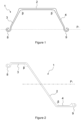
- the metal sheet pile 1 first comprises, in cross-section perpendicular to its length, a central web 2 and a first inclined flange 3 and a second inclined flange 4 both extending outwardly from the lateral edges of the central web.
- the metal sheet pile is preferably made of steel and obtained by hot rolling.
- the central web is preferably substantially flat and lies in a plane. It is preferably of constant thickness across the cross-section.
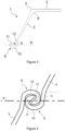
- the two inclined flanges extend either on the same side of the central web so as to form a U-shaped sheet pile (as illustrated on Figure 1 ) or on two different sides so as to form a Z-shaped sheet pile (as illustrated on Figure 2 ).
- the angle ⁇ between the central web and one inclined flange is generally comprised between 110° and 150°.
- the sheet pile is preferably a U-shaped sheet pile.
- inclined flanges 3 and 4 are symmetrical.
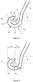
- the inclined flange is of constant thickness across the cross-section. According to the variant illustrated on Figure 3 , its thickness decreases towards the extremity of the sheet pile, i.e. towards the interlock.
- the inclined flange has a conical cross-section. More preferably, the two sides of the flange converge in the direction of the interlock with a convergence rate comprised between 1 and 3%. The convergence rate is defined as the difference between the thicknesses at two points of the wing divided by the distance between these two points.
- the conicity of the inclined flange(s) improves the drivability of the metal sheet pile while optimizing its weight.
- the inclined flange(s) 3, 4 can comprise a shoulder 5 located at the junction between the central web 2 and the inclined flange(s).
- shoulder it is meant a material extension projecting with respect to the imaginary plane which prolongs the external face of the inclined flange towards the central web. The shoulder increases the resistance modulus and thus the reusability of the metal sheet pile.
- the central web can comprise an extension (not illustrated) projecting with respect to the imaginary plane which prolongs the external face of the central web towards the inclined flange.
- the bending radius at the junction between the central web 2 and the inclined flange(s) 3, 4 can be increased so as to thicken the connection of the central web and the inclined flange(s) from the inside.
- the concave corners 6 delimited by the two flange/web connections are substantially flattened by a material surcharge. This increases the mechanical resistance of the metal sheet pile and, thus, improves its reusability.
- the extremity of the inclined flanges are inclined at an angle ⁇ of at least 97° with respect to the neutral axis P 1 of the metal sheet pile.
- the neutral axis is defined as the axis along which there are no stresses or strains.
- the neutral axis is always parallel to the y-y axis of the sheet pile as defined in EN1993-5:2007.
- the interlocks are on the neutral axis; in other words, the central web is parallel to the neutral axis.
- the neutral axis is parallel to the inclined flanges and cross the central web in its middle.
- angle ⁇ is comprised between 97° and 101° in order to have the best compromise between rotational capacity and resistance to declutching.
- the flange is straight in that case.
- the extremity of the inclined flange is bent so that angles ⁇ and ⁇ differ. Thanks to this bent at the extremity of the inclined flange, angle ⁇ can be adjusted to optimize the tension modulus of the sheet pile while angle ⁇ is adjusted differently to optimize the rotational capacity of the sheet pile.
- one of the extremities of the inclined flanges is inclined with respect to the neutral axis in the form of a protrusion thickening the extremity in direction of the neutral axis. The other extremity is bent so that the interlocking is possible.
- the metal sheet pile 1 further comprises a first interlock 8 and a second interlock 9 extending from the extremity of respectively the first inclined flange 3 and the second inclined flange 4.
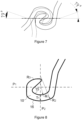
- Interlocks 8 and 9 are designed so that interlock 8 of a first metal sheet pile can slot into interlock 9 of a second metal sheet pile, as illustrated on Figure 4 .
- each of the two interlocks 8, 9 comprises a bottom part 10 convexly extending outward from the extremity of the inclined flange and a finger 11 of substantially triangular cross-section, extending upward from the bottom part.
- the extremity of the inclined flange, the bottom part and the finger delimit a chamber 12.
- the finger of a first metal sheet pile can slot into the chamber of a second metal sheet pile so as to connect the two sheet piles.
- the bottom part 10 comprises an internal side 13 and an external side 14 separated by a radial thickness T 1 .
- internal side it is meant the side facing the chamber 12 and which extends from the external face of the inclined flange.
- the external side is thus the side at the opposite from the chamber and which extends from the internal face of the inclined flange.
- the internal side 13 extends along a first portion of circle 15 whose center lies in a plane P 2 perpendicular to plane P 1 and whose radius of curvature R 1 satisfies inequation (i) : 1.5 ⁇ R 1 / T 1 ⁇ 5
- the radial thickness T 1 is defined as the thickness measured along the perpendicular bisector of the first portion of circle 15.
- the center of the circle corresponding to the first portion of circle 15 is located above the bottom part.
- the chamber 12 presents a rounded shape which improves the rotational capacity of the sheet pile.
- the rounded bottom part thus strongly limits the risk of deforming the interlock when the sheet pile is driven in the ground and/or removed before reuse.
- the ratio between the radius of curvature R 1 and the radial thickness T 1 is comprised between 1.5 and 2.5. This was found to be the best compromise between rotational capacity and resistance to declutching.
- the perpendicular bisector of the first portion of circle 15 is within plane P 2 . This symmetry favors the interlocking of two adjacent sheet piles.
- the first portion of circle 15 has an angle of aperture ⁇ comprised between 30° and 140°, depending on the radius of curvature R 1 .
- This favors a smooth transition between the bottom part and, on one side, the finger and, on the other side, the inclined flange.
- the radius of curvature R 1 and the angle of aperture ⁇ satisfy the inequation (iii): 100116 R 1 ⁇ 2.499 ⁇ ⁇ ⁇ 3044 R 1 ⁇ 1.122
- the external side 14 extends along a second portion of circle 16 whose center lies in plane P 2 and whose radius of curvature R 2 is at least equal to R 1 +T1.
- the perpendicular bisector of the first portion of circle 15 and the perpendicular bisector of the second portion of circle 16 are identical. This ensures a symmetrical distribution of the material on both sides of the perpendicular bisector of the first portion of circle 15. This favors a homogeneous behavior of the interlock.
- the second portion of circle 16 and the first portion of circle are concentric.
- R 2 is equal to R 1 +T1.
- R 2 is greater than R 1 +T1.
- the finger 11 is of substantially triangular cross-section, extending upward from the bottom part, pointing towards the inclined flange.
- the cross-section of finger 11 is substantially a rectangular triangle, whose hypotenuse 17 is facing the chamber 12, whose lateral side 18 is parallel to plane P 2 and whose top side 19 is parallel to plane P 1 .
- the vertex between the lateral side and the top side is rounded.
- the radius of curvature R 3 of the rounded vertex is equal to the radius of curvature R 1 of the internal side 13 of the bottom part 10. This favors the interlocking of two interlocks and improves the rotational capacity of the sheet pile.
- the vertex between the top side and the hypotenuse is rounded too to favors the interlocking of two interlocks.
- the finger 11 has a projected width W 1 which is defined as the distance along a plane parallel to P 1 between the fingertip 20 and the plane P 3 , perpendicular to P 1 , which contains the lateral side 18.
- the finger 11 is separated from the extremity of the inclined flange by the distance W 2 , which is defined as the distance along a plane parallel to P 1 between the fingertip 20 and the inclined flange.
- the finger 11 is positioned so that W1 and W2 satisfy the inequation (ii): 1.2 ⁇ W 1 / W 2 ⁇ 1.7
- the two interlocks 8, 9 can more easily interlock and rotate while maintaining a good resistance to declutching. Thanks to this ratio, and in combination with the rounded shape of the bottom part 10 and the inclination of the extremity of the inclined flange, the rotational capacity of the sheet pile is improved. This improved rotational capacity strongly limits the risk of deforming the interlock when the sheet pile is driven in the ground and/or removed before reuse.
- the ratio between the projected width W 1 of the finger and the distance W 2 is comprised between 1.45 and 1.55. This was found to be the best compromise between rotational capacity and resistance to declutching.
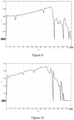
- Numerical simulations with the Qform metal forming simulation software have been performed on the metal sheet piles according to the invention.
- the performed simulation is similar to a tensile test where a continuous axial displacement is imposed in the tool direction and the force on the clamp is measured.
- the results are presented in Figure 9 where X is the time in seconds and Y is the force in MN. They show that, when R 2 is equal to R 1 +T 1 , the interlock resists a load of 0.085 MN before declutching, which is similar to the performances obtained with the metal sheet pile from the prior art.
- the results presented in Figure 10 show that increasing the radius of curvature R 2 compared to R 1 (as illustrated on Figure 8 ) further improves the resistance to declutching.
Landscapes
- Engineering & Computer Science (AREA)
- Structural Engineering (AREA)
- Chemical & Material Sciences (AREA)
- Composite Materials (AREA)
- Life Sciences & Earth Sciences (AREA)
- General Life Sciences & Earth Sciences (AREA)
- Mining & Mineral Resources (AREA)
- Paleontology (AREA)
- Civil Engineering (AREA)
- General Engineering & Computer Science (AREA)
- Bulkheads Adapted To Foundation Construction (AREA)
Claims (13)
- Metallene Spundwand (1), die im Querschnitt einen Mittelsteg (2) aufweist, der von nach außen geneigten Flanschen (3, 4) begrenzt wird, deren Enden in einem Winkel α von mindestens 97° gegenüber der neutralen Achse P1 der metallenen Spundwand geneigt sind und durch ein Schloss (8, 9) verlängert werden, das aus aufeinanderfolgenden Teilen besteht:- Ein Bodenteil (10), das sich vom Ende des geneigten Flansches konvex nach außen erstreckt, mit einer Innenseite (13) und einer Außenseite (14), die durch eine radiale Dicke T1 getrennt sind, wobei sich die Innenseite entlang eines ersten Kreisabschnitts (15) erstreckt, dessen Mittelpunkt in einer Ebene P2 senkrecht zur Ebene P1 liegt und dessen Krümmungsradius R1 die Ungleichung (i) erfüllt:
 - Ein Finger (11) mit im wesentlichen dreieckigem Querschnitt, der sich vom Bodenteil nach oben erstreckt, in Richtung des geneigten Flansches zeigt und eine vorstehende Breite W1 auf der Ebene P1 hat, wobei die Fingerspitze (20) von dem geneigten Flansch durch einen Abstand W2 getrennt ist, wobei W1 und W2 die Ungleichung (ii) erfüllen:
- Metallene Spundwand nach Anspruch 1, wobei der Winkel α zwischen 97° und 101° liegt.
- Metallene Spundwand nach einem der Ansprüche 1 oder 2, wobei das Verhältnis zwischen dem Krümmungsradius R1 und der radialen Dicke T1 zwischen 1,5 und 2,5 liegt.
- Metallene Spundwand nach einem der vorhergehenden Ansprüche, wobei die Mittelsenkrechte des ersten Kreisabschnitts (15) in der Ebene P2 liegt.
- Metallene Spundwand nach einem der vorhergehenden Ansprüche, wobei der erste Kreisabschnitt (15) einen Öffnungswinkel γ zwischen 20° und 137° aufweist.
- Metallene Spundwand nach einem der vorhergehenden Ansprüche, wobei die Mittelsenkrechte des ersten Kreisabschnitts (15) und die Mittelsenkrechte des zweiten Kreisabschnitts (16) identisch sind.
- Metallene Spundwand nach einem der vorhergehenden Ansprüche, wobei R2 gleich R1+T1 ist.
- Metallene Spundwand nach einem der vorhergehenden Ansprüche, dadurch gekennzeichnet, dass der Finger (11) eine Seitenfläche (18) und eine Oberseite (19) aufweist, deren Scheitelpunkt mit einem Krümmungsradius R3 abgerundet ist, der gleich dem Krümmungsradius R1 der Innenseite (13) des Bodenteils (10) ist.
- Metallene Spundwand nach einem der vorhergehenden Ansprüche, wobei das Verhältnis zwischen der vorstehenden Breite W1 des Fingers und dem Abstand W2 zwischen 1,45 und 1,55 liegt.
- Metallene Spundwand nach einem der vorhergehenden Ansprüche, wobei mindestens einer der geneigten Flansche (3, 4) zwei Seiten aufweist, die in Richtung des Schlosses mit einer Konvergenzrate zwischen 1 und 3 % konvergieren.
- Metallene Spundwand nach einem der vorhergehenden Ansprüche, wobei mindestens einer der geneigten Flansche (3, 4) eine Schulter aufweist, die an der Verbindung zwischen dem Mittelsteg (2) und mindestens einem der geneigten Flansche (3, 4) angeordnet ist.
- Metallene Spundwand nach einem der vorhergehenden Ansprüche, dadurch gekennzeichnet, dass die Verbindungen zwischen dem Mittelsteg und den geneigten Flanschen konkave Ecken (6) begrenzen, die durch einen Materialzuschlag im Wesentlichen abgeflacht sind.
- Erdstützbauwerk, bestehend aus mindestens zwei miteinander verriegelten metallenen Spundwänden nach einem der Ansprüche 1 bis 12.
Applications Claiming Priority (1)
| Application Number | Priority Date | Filing Date | Title |
|---|---|---|---|
| PCT/IB2019/060119 WO2021105740A1 (en) | 2019-11-25 | 2019-11-25 | Reusable metal sheet pile |
Publications (2)
| Publication Number | Publication Date |
|---|---|
| EP4065775A1 EP4065775A1 (de) | 2022-10-05 |
| EP4065775B1 true EP4065775B1 (de) | 2025-03-26 |
Family
ID=68771728
Family Applications (1)
| Application Number | Title | Priority Date | Filing Date |
|---|---|---|---|
| EP19813945.3A Active EP4065775B1 (de) | 2019-11-25 | 2019-11-25 | Wiederverwendbare spundwand aus metal |
Country Status (3)
| Country | Link |
|---|---|
| EP (1) | EP4065775B1 (de) |
| PL (1) | PL4065775T3 (de) |
| WO (1) | WO2021105740A1 (de) |
Family Cites Families (4)
| Publication number | Priority date | Publication date | Assignee | Title |
|---|---|---|---|---|
| GB326275A (en) * | 1928-12-24 | 1930-03-13 | Richard Henry Annison | Improvements in and relating to interlocking sheet piling |
| WO2000028157A1 (de) * | 1998-11-10 | 2000-05-18 | Georg Wall | Verbindungselement für spundbohlen |
| CN201386275Y (zh) * | 2008-12-23 | 2010-01-20 | 王银 | 具有涡旋配合结构的u形钢板桩 |
| CN206245308U (zh) * | 2016-12-06 | 2017-06-13 | 南京博睿工程咨询有限公司 | 防水钢板桩 |
-
2019
- 2019-11-25 EP EP19813945.3A patent/EP4065775B1/de active Active
- 2019-11-25 PL PL19813945.3T patent/PL4065775T3/pl unknown
- 2019-11-25 WO PCT/IB2019/060119 patent/WO2021105740A1/en not_active Ceased
Also Published As
| Publication number | Publication date |
|---|---|
| PL4065775T3 (pl) | 2025-06-02 |
| WO2021105740A1 (en) | 2021-06-03 |
| EP4065775A1 (de) | 2022-10-05 |
Similar Documents
| Publication | Publication Date | Title |
|---|---|---|
| EP1420117B1 (de) | Metallspundwand | |
| US20250034825A1 (en) | Sheet-pile module and sheet-pile wall consisting of sheet-pile modules | |
| US7360969B2 (en) | Z-shaped sheet piling | |
| JP6108031B2 (ja) | 鋼矢板 | |
| KR100497424B1 (ko) | 항타 저항이 적은 u자형 시트 파일 | |
| US3247673A (en) | Laminated retaining wall and method of constructing same | |
| RU2701265C1 (ru) | Шпунтовая стенка | |
| EP4065775B1 (de) | Wiederverwendbare spundwand aus metal | |
| RU2692385C1 (ru) | Шпунтовая свая | |
| CN101146959A (zh) | 连接型材以及使用该种连接型材的组合板桩墙 | |
| KR20090006672A (ko) | 말뚝과 이 말뚝을 이용한 옹벽 | |
| JP3603793B2 (ja) | 地中連続壁用鋼材および地中連続壁 | |
| SG172878A1 (en) | Combined steel sheet pile, earth-retaining wall formed by combined steel sheet pile, and method of selecting combined steel sheet pile | |
| WO2013171909A1 (ja) | 組合せ鋼製壁 | |
| JP2020118188A (ja) | 連結装置 | |
| JP2006241816A (ja) | 地中連続壁 | |
| US1341949A (en) | Sheet-piling | |
| KR20200006648A (ko) | 토류벽 및 그 시공방법 | |
| JP2009155897A (ja) | ハット形鋼矢板 | |
| US1721643A (en) | Metal sheet piling | |
| JP5257470B2 (ja) | 組合せ鋼製壁 | |
| KR20140139050A (ko) | Z형강 시트 파일, 당해 z형강 시트 파일로 형성된 강 시트 파일벽 | |
| JP3911261B2 (ja) | 圧延鋼矢板 | |
| JP2012167430A (ja) | Z形鋼矢板、該z形鋼矢板で形成された鋼矢板壁 | |
| US2287018A (en) | Metal sheet piling |
Legal Events
| Date | Code | Title | Description |
|---|---|---|---|
| STAA | Information on the status of an ep patent application or granted ep patent |
Free format text: STATUS: UNKNOWN |
|
| STAA | Information on the status of an ep patent application or granted ep patent |
Free format text: STATUS: THE INTERNATIONAL PUBLICATION HAS BEEN MADE |
|
| PUAI | Public reference made under article 153(3) epc to a published international application that has entered the european phase |
Free format text: ORIGINAL CODE: 0009012 |
|
| STAA | Information on the status of an ep patent application or granted ep patent |
Free format text: STATUS: REQUEST FOR EXAMINATION WAS MADE |
|
| 17P | Request for examination filed |
Effective date: 20220627 |
|
| AK | Designated contracting states |
Kind code of ref document: A1 Designated state(s): AL AT BE BG CH CY CZ DE DK EE ES FI FR GB GR HR HU IE IS IT LI LT LU LV MC MK MT NL NO PL PT RO RS SE SI SK SM TR |
|
| DAV | Request for validation of the european patent (deleted) | ||
| DAX | Request for extension of the european patent (deleted) | ||
| GRAP | Despatch of communication of intention to grant a patent |
Free format text: ORIGINAL CODE: EPIDOSNIGR1 |
|
| STAA | Information on the status of an ep patent application or granted ep patent |
Free format text: STATUS: GRANT OF PATENT IS INTENDED |
|
| INTG | Intention to grant announced |
Effective date: 20241028 |
|
| GRAS | Grant fee paid |
Free format text: ORIGINAL CODE: EPIDOSNIGR3 |
|
| GRAA | (expected) grant |
Free format text: ORIGINAL CODE: 0009210 |
|
| STAA | Information on the status of an ep patent application or granted ep patent |
Free format text: STATUS: THE PATENT HAS BEEN GRANTED |
|
| P01 | Opt-out of the competence of the unified patent court (upc) registered |
Free format text: CASE NUMBER: APP_4120/2025 Effective date: 20250125 |
|
| AK | Designated contracting states |
Kind code of ref document: B1 Designated state(s): AL AT BE BG CH CY CZ DE DK EE ES FI FR GB GR HR HU IE IS IT LI LT LU LV MC MK MT NL NO PL PT RO RS SE SI SK SM TR |
|
| REG | Reference to a national code |
Ref country code: GB Ref legal event code: FG4D |
|
| REG | Reference to a national code |
Ref country code: CH Ref legal event code: EP |
|
| REG | Reference to a national code |
Ref country code: DE Ref legal event code: R096 Ref document number: 602019067846 Country of ref document: DE |
|
| REG | Reference to a national code |
Ref country code: IE Ref legal event code: FG4D Ref country code: NL Ref legal event code: FP |
|
| PG25 | Lapsed in a contracting state [announced via postgrant information from national office to epo] |
Ref country code: RS Free format text: LAPSE BECAUSE OF FAILURE TO SUBMIT A TRANSLATION OF THE DESCRIPTION OR TO PAY THE FEE WITHIN THE PRESCRIBED TIME-LIMIT Effective date: 20250626 |
|
| PG25 | Lapsed in a contracting state [announced via postgrant information from national office to epo] |
Ref country code: FI Free format text: LAPSE BECAUSE OF FAILURE TO SUBMIT A TRANSLATION OF THE DESCRIPTION OR TO PAY THE FEE WITHIN THE PRESCRIBED TIME-LIMIT Effective date: 20250326 |
|
| REG | Reference to a national code |
Ref country code: LT Ref legal event code: MG9D |
|
| PG25 | Lapsed in a contracting state [announced via postgrant information from national office to epo] |
Ref country code: NO Free format text: LAPSE BECAUSE OF FAILURE TO SUBMIT A TRANSLATION OF THE DESCRIPTION OR TO PAY THE FEE WITHIN THE PRESCRIBED TIME-LIMIT Effective date: 20250626 |
|
| PG25 | Lapsed in a contracting state [announced via postgrant information from national office to epo] |
Ref country code: HR Free format text: LAPSE BECAUSE OF FAILURE TO SUBMIT A TRANSLATION OF THE DESCRIPTION OR TO PAY THE FEE WITHIN THE PRESCRIBED TIME-LIMIT Effective date: 20250326 |
|
| PG25 | Lapsed in a contracting state [announced via postgrant information from national office to epo] |
Ref country code: LV Free format text: LAPSE BECAUSE OF FAILURE TO SUBMIT A TRANSLATION OF THE DESCRIPTION OR TO PAY THE FEE WITHIN THE PRESCRIBED TIME-LIMIT Effective date: 20250326 |
|
| PG25 | Lapsed in a contracting state [announced via postgrant information from national office to epo] |
Ref country code: GR Free format text: LAPSE BECAUSE OF FAILURE TO SUBMIT A TRANSLATION OF THE DESCRIPTION OR TO PAY THE FEE WITHIN THE PRESCRIBED TIME-LIMIT Effective date: 20250627 Ref country code: BG Free format text: LAPSE BECAUSE OF FAILURE TO SUBMIT A TRANSLATION OF THE DESCRIPTION OR TO PAY THE FEE WITHIN THE PRESCRIBED TIME-LIMIT Effective date: 20250326 |
|
| PG25 | Lapsed in a contracting state [announced via postgrant information from national office to epo] |
Ref country code: SE Free format text: LAPSE BECAUSE OF FAILURE TO SUBMIT A TRANSLATION OF THE DESCRIPTION OR TO PAY THE FEE WITHIN THE PRESCRIBED TIME-LIMIT Effective date: 20250326 |
|
| REG | Reference to a national code |
Ref country code: AT Ref legal event code: MK05 Ref document number: 1779088 Country of ref document: AT Kind code of ref document: T Effective date: 20250326 |
|
| PG25 | Lapsed in a contracting state [announced via postgrant information from national office to epo] |
Ref country code: SM Free format text: LAPSE BECAUSE OF FAILURE TO SUBMIT A TRANSLATION OF THE DESCRIPTION OR TO PAY THE FEE WITHIN THE PRESCRIBED TIME-LIMIT Effective date: 20250326 |
|
| PG25 | Lapsed in a contracting state [announced via postgrant information from national office to epo] |
Ref country code: PT Free format text: LAPSE BECAUSE OF FAILURE TO SUBMIT A TRANSLATION OF THE DESCRIPTION OR TO PAY THE FEE WITHIN THE PRESCRIBED TIME-LIMIT Effective date: 20250728 Ref country code: ES Free format text: LAPSE BECAUSE OF FAILURE TO SUBMIT A TRANSLATION OF THE DESCRIPTION OR TO PAY THE FEE WITHIN THE PRESCRIBED TIME-LIMIT Effective date: 20250326 |
|
| PG25 | Lapsed in a contracting state [announced via postgrant information from national office to epo] |
Ref country code: IT Free format text: LAPSE BECAUSE OF FAILURE TO SUBMIT A TRANSLATION OF THE DESCRIPTION OR TO PAY THE FEE WITHIN THE PRESCRIBED TIME-LIMIT Effective date: 20250326 |
|
| PG25 | Lapsed in a contracting state [announced via postgrant information from national office to epo] |
Ref country code: AT Free format text: LAPSE BECAUSE OF FAILURE TO SUBMIT A TRANSLATION OF THE DESCRIPTION OR TO PAY THE FEE WITHIN THE PRESCRIBED TIME-LIMIT Effective date: 20250326 |
|
| PG25 | Lapsed in a contracting state [announced via postgrant information from national office to epo] |
Ref country code: EE Free format text: LAPSE BECAUSE OF FAILURE TO SUBMIT A TRANSLATION OF THE DESCRIPTION OR TO PAY THE FEE WITHIN THE PRESCRIBED TIME-LIMIT Effective date: 20250326 |
|
| PG25 | Lapsed in a contracting state [announced via postgrant information from national office to epo] |
Ref country code: RO Free format text: LAPSE BECAUSE OF FAILURE TO SUBMIT A TRANSLATION OF THE DESCRIPTION OR TO PAY THE FEE WITHIN THE PRESCRIBED TIME-LIMIT Effective date: 20250326 |
|
| PG25 | Lapsed in a contracting state [announced via postgrant information from national office to epo] |
Ref country code: SK Free format text: LAPSE BECAUSE OF FAILURE TO SUBMIT A TRANSLATION OF THE DESCRIPTION OR TO PAY THE FEE WITHIN THE PRESCRIBED TIME-LIMIT Effective date: 20250326 |
|
| PG25 | Lapsed in a contracting state [announced via postgrant information from national office to epo] |
Ref country code: IS Free format text: LAPSE BECAUSE OF FAILURE TO SUBMIT A TRANSLATION OF THE DESCRIPTION OR TO PAY THE FEE WITHIN THE PRESCRIBED TIME-LIMIT Effective date: 20250726 |
|
| PGFP | Annual fee paid to national office [announced via postgrant information from national office to epo] |
Ref country code: LU Payment date: 20251022 Year of fee payment: 7 Ref country code: NL Payment date: 20251022 Year of fee payment: 7 |
|
| REG | Reference to a national code |
Ref country code: DE Ref legal event code: R097 Ref document number: 602019067846 Country of ref document: DE |
|
| PGFP | Annual fee paid to national office [announced via postgrant information from national office to epo] |
Ref country code: DE Payment date: 20251022 Year of fee payment: 7 |
|
| PGFP | Annual fee paid to national office [announced via postgrant information from national office to epo] |
Ref country code: GB Payment date: 20251023 Year of fee payment: 7 |
|
| PG25 | Lapsed in a contracting state [announced via postgrant information from national office to epo] |
Ref country code: DK Free format text: LAPSE BECAUSE OF FAILURE TO SUBMIT A TRANSLATION OF THE DESCRIPTION OR TO PAY THE FEE WITHIN THE PRESCRIBED TIME-LIMIT Effective date: 20250326 |
|
| PGFP | Annual fee paid to national office [announced via postgrant information from national office to epo] |
Ref country code: FR Payment date: 20251022 Year of fee payment: 7 |
|
| PGFP | Annual fee paid to national office [announced via postgrant information from national office to epo] |
Ref country code: BE Payment date: 20251022 Year of fee payment: 7 |
|
| PGFP | Annual fee paid to national office [announced via postgrant information from national office to epo] |
Ref country code: CZ Payment date: 20251104 Year of fee payment: 7 |
|
| PGFP | Annual fee paid to national office [announced via postgrant information from national office to epo] |
Ref country code: PL Payment date: 20251022 Year of fee payment: 7 |
|
| PLBE | No opposition filed within time limit |
Free format text: ORIGINAL CODE: 0009261 |
|
| STAA | Information on the status of an ep patent application or granted ep patent |
Free format text: STATUS: NO OPPOSITION FILED WITHIN TIME LIMIT |
|
| REG | Reference to a national code |
Ref country code: CH Ref legal event code: L10 Free format text: ST27 STATUS EVENT CODE: U-0-0-L10-L00 (AS PROVIDED BY THE NATIONAL OFFICE) Effective date: 20260211 |
|
| 26N | No opposition filed |
Effective date: 20260105 |