EP4065396B1 - Dichtungsstrang mit individuellem identifikationsmittel und verfahren zur applikation - Google Patents
Dichtungsstrang mit individuellem identifikationsmittel und verfahren zur applikation Download PDFInfo
- Publication number
- EP4065396B1 EP4065396B1 EP20807663.8A EP20807663A EP4065396B1 EP 4065396 B1 EP4065396 B1 EP 4065396B1 EP 20807663 A EP20807663 A EP 20807663A EP 4065396 B1 EP4065396 B1 EP 4065396B1
- Authority
- EP
- European Patent Office
- Prior art keywords
- sealing
- strand
- identification means
- profile
- tolerance
- Prior art date
- Legal status (The legal status is an assumption and is not a legal conclusion. Google has not performed a legal analysis and makes no representation as to the accuracy of the status listed.)
- Active
Links
Images


Classifications
-
- B—PERFORMING OPERATIONS; TRANSPORTING
- B60—VEHICLES IN GENERAL
- B60J—WINDOWS, WINDSCREENS, NON-FIXED ROOFS, DOORS, OR SIMILAR DEVICES FOR VEHICLES; REMOVABLE EXTERNAL PROTECTIVE COVERINGS SPECIALLY ADAPTED FOR VEHICLES
- B60J10/00—Sealing arrangements
- B60J10/45—Assembling sealing arrangements with vehicle parts
-
- B—PERFORMING OPERATIONS; TRANSPORTING
- B65—CONVEYING; PACKING; STORING; HANDLING THIN OR FILAMENTARY MATERIAL
- B65H—HANDLING THIN OR FILAMENTARY MATERIAL, e.g. SHEETS, WEBS, CABLES
- B65H75/00—Storing webs, tapes, or filamentary material, e.g. on reels
- B65H75/02—Cores, formers, supports, or holders for coiled, wound, or folded material, e.g. reels, spindles, bobbins, cop tubes, cans, mandrels or chucks
- B65H75/18—Constructional details
- B65H75/182—Identification means
-
- B—PERFORMING OPERATIONS; TRANSPORTING
- B65—CONVEYING; PACKING; STORING; HANDLING THIN OR FILAMENTARY MATERIAL
- B65H—HANDLING THIN OR FILAMENTARY MATERIAL, e.g. SHEETS, WEBS, CABLES
- B65H2701/00—Handled material; Storage means
- B65H2701/30—Handled filamentary material
- B65H2701/39—Other types of filamentary materials or special applications
- B65H2701/3913—Extruded profiled strands
Definitions
- the invention relates to a sealing strip according to the preamble of claim 1. Furthermore, the invention relates to a device for receiving such a sealing strip during its transport to a processing location and to a method for applying such sealing strips to a vehicle body.
- Devices for receiving a sealing strip in particular an extruded one, during its transport to a processing location are known from use, which comprise a coil that receives the sealing strip as a winding.
- the wound coil is intended for temporary inclusion in an application device that continuously processes the sealing strip into seals on vehicle bodies while the coil is rotated.
- a continuous profile strip possibly composed of individual lengths, is wound on the coil in the form of a so-called endless strand, from which the sealing strips are formed by cutting them off. As soon as the last sealing strip has been removed, the empty coil is removed and a new coil with wound profile strip is fed to the application device.
- the coils are fed to the application device at random or in the order in which they are delivered according to the "first in - first out” (FIFO) principle.
- manufacturing tolerances of the profile strand and thus of the sealing strands are not taken into account and deviations in the geometric and/or physical properties within the manufacturing tolerance between the sealing strands of two spools.
- These geometric and/or physical properties can also vary, e.g. due to fluctuations in the manufacturing process, not only from spool to spool, but also over the length of the profile strand or sealing strand wound on a spool.
- the first 300 m of the profile strand may be closer to the maximum permissible tolerance, the next 300 m closer to the nominal range, and the last 400 m closer to the minimum range of the permissible hardness.
- the changes in the technical properties of the profile strand and the sealing strands over the length are within the permissible tolerances, this can result in losses in terms of system availability, application quality, and smooth operation of the application device.
- the deviations can lead to the position of the sealing strip changing slightly during application, thus resulting in a changed position of the seal on a vehicle body.
- a device for applying a sealing profile to the body of a motor vehicle whereby a controlled tensile stress when applying the sealing profile is intended to prevent the sealing profile from unintentionally coming off in the area of tight curve radii of the vehicle body.
- the sealing profile has machine-readable data, for example on a bar code, which is read by the application device and used to set the desired tensile stress.
- EP 2 151 410 A1 and US 2019/092152 A1 It is known to equip a storage device in the form of a coil for a strand-shaped winding material with an electronic processor element, for example in the form of an RFID tag for storing material parameters such as the position of defects. According to the EN 10 2005 028069 A1 In known processes, the faulty areas of a sealing profile are detected and stored during production in order to later separate the sections identified as defective.
- the object of the invention is therefore to enable a higher process reliability (repeatability) and quality of the application of sealing strips to a vehicle body.
- This object is achieved in that one or more selected physical and/or geometric properties of the sealing strip lie within a predetermined manufacturing tolerance and that each manufacturing tolerance is divided into several tolerance ranges, wherein the identification means is designed to enable access to a strip-specific tolerance range of the entire sealing strip or to tolerance ranges of different sub-areas of the sealing strip.
- the identification means which is assigned to the sealing strip for providing individual features for the sealing strip, can be arranged directly on the sealing strip, its packaging or a transport device for the sealing strip.
- the identification means can be an electronically readable identification means, for example a barcode, a QR code or an RFID chip.
- the identification means can have a human-readable coding, such as a color or number code.
- the identification means advantageously enables access to overall individual features of the entire profile strand or sealing strand that are relevant for the application or, if applicable, differing features for different sub-areas of the profile strand or sealing strand.
- Individual features are to be understood as strand-specific features/information that distinguish one sealing strand from another, similar sealing strand, on the basis of which an individual adaptation of the application device should be carried out.
- Similar sealing strands are identically constructed sealing strands that, apart from deviations in production, such as manufacturing tolerances or the position/number of defects, are identically designed and intended for the same position on a vehicle body.
- the strand-specific individual features include, for example, the deviation from target values at certain control points, the inventive assignment to tolerance ranges, which are formed by dividing the range of a certain permissible manufacturing tolerance, and the number and/or position of defects.
- the tolerance ranges can in particular relate to one or more selected physical and/or geometric properties of the sealing strip, such as the geometric dimensions of certain cross-sectional areas of the sealing strip or of the entire sealing strip, the density and/or hardness the materials used, the friction coefficient of the materials used and/or the surfaces (coatings) such as anti-friction varnishes or flocking.
- the identification means can therefore also be designed to enable access to characteristics relevant to the application that differ from one another over the length of the profile strand or sealing strand for different sub-areas of the profile strand or sealing strand.
- the size and number of sub-areas can be freely selected so that a desired resolution can be set.
- the application system can be automatically adjusted to the respective tolerance levels of the technical properties of the next section of the sealing strip to be processed by adjusting application parameters (or can adjust itself under computer control) shortly before or during application, thereby improving the quality of the application.
- the identification means can, for example, be easily read out electronically and the sealing strips can be applied to a vehicle body according to these features, preferably fully automatically, as will be described in more detail below.
- the features can be contained in the identification means or the identification means can enable an assignment to an external data set, for example a data set stored in a data storage device.
- the data storage device can be, for example, a data storage device (cloud storage) available via the Internet or a network, to which both the manufacturer of the sealing strip and the processor who applies the sealing strip to the motor vehicle body preferably have access.
- a device for receiving a particularly extruded sealing strip during its transport to a processing location with an identification means for providing individual characteristics to the sealing strip and a coil that accommodates the sealing strip as a winding, in which the wound coil is provided for temporary inclusion in an application device that continuously processes the sealing strip into seals on vehicle bodies while rotating the coil, wherein one or more selected physical and/or geometric properties of the sealing strip are each within a predetermined manufacturing tolerance.
- the device is characterized in that each manufacturing tolerance is divided into several tolerance ranges and the identification means is designed to enable access to a strip-specific tolerance range of the entire sealing strip or to tolerance ranges of different sub-areas of the sealing strip.
- the identification means can be designed, for example, as an electronically readable identification means, in particular as a barcode, QR code or RFID chip, and attached to the device in an electronically readable manner.
- the identification means can have a human-readable coding, such as a color or number code.
- the identification means advantageously enables access to overall individual features of the sealing strands wound on the coil that are relevant for the application or to different features of different sub-areas of the sealing strands. These can include, for example, the tolerance ranges according to the invention described above and the number and/or position of defects.
- the identification means can, for example, be read out electronically, the coils can be fed to an application device according to the identification means and the sealing strands can be applied to a vehicle body according to these features, preferably fully automatically, as will be described in more detail below.
- the features can advantageously be contained in the identification means or the identification means can enable an assignment to an external data set, for example a data set stored in a data storage device.
- the data storage device can, for example, be a data storage device (cloud storage) available via the Internet or a network, to which both the manufacturer of the sealing strip and the processor who applies the sealing strip to the motor vehicle body preferably have access.
- a method for applying sealing strands to a vehicle body is claimed.
- the method in which individual characteristics of the sealing strands are recorded before application and the application is adapted depending on this, is characterized in that several sealing strands are present, in which one or more selected physical and/or geometric properties are each within a range of a predetermined permissible manufacturing tolerance, wherein each manufacturing tolerance is divided into several tolerance ranges and the identification means of the sealing strands can be used to determine the assignment of the respective sealing strand to a tolerance range.
- a certain dimension of the sealing strand in cross-section can have a permissible manufacturing tolerance of +/- 0.2 mm.
- This manufacturing tolerance can further be divided, for example, into four equal tolerance ranges, i.e.
- the tolerance ranges [0.2 mm; 0.1 mm[, [0.1 mm; 0.0 mm[, [0.0 mm; - 0.1 mm[ and [- 0.1 mm; - 0.2 mm] and the allocation of the respective sealing strip to a tolerance range can be taken from the identification means.
- corresponding tolerance ranges can also be defined within the manufacturing tolerance, for example regarding the friction value of a surface or surface coating, the density, the hardness, etc. of the sealing strip and allocated to the sealing strips via the identification means.
- the adjustment can refer to a specific order of application of the sealing strips and/or an individual adjustment of the application device, as explained in more detail below.
- the sealing strands can advantageously be formed by cutting them off from a profile strand wound on a spool and individual characteristics of the sealing strands can be recorded after the profile strand has been unwound and/or before the profile strand is wound onto the spool. If individual characteristics are recorded before the profile strand is wound onto the spool, an identification means, particularly electronically readable, can be assigned to the profile strand or the sealing strand, via which the individual characteristics can be accessed. This means that the individual characteristics of the profile strand of each spool can be read out before the profile strand is unwound and the appropriate spool for the application can be selected in advance.
- a profile strand of this type also known as an endless seal, enables particularly simple and space-saving transport to the Processor where the sealing strips are separated and attached/applied to a vehicle body.
- the identification means advantageously enables access to overall individual features of the entire profile strand or sealing strand that are relevant for the application or, if applicable, to different features of different sub-areas of the profile strand or sealing strand.
- intelligent assignment of coils or sealing strands to special application systems can ensure that only sealing strands are installed at a specific location on the vehicle body (e.g. the left rear vehicle door of a four-door vehicle) in which one or more selected physical and/or geometric properties are identical or are within a defined range that is smaller than the overall permissible tolerance range for this feature.
- the selection of a sealing strip to be applied next from several similar sealing strips can be made on the basis of the determined individual characteristics or the identification means.
- the sealing strips can be applied to the vehicle body by means of an application device which is adjusted depending on the determined characteristics or the identification means. This can ensure that sealing strips are processed one after the other which have defined geometric and/or physical properties, in particular with small deviations, and/or additionally the application device is adapted to ensure that the sealing strips on the vehicle body function as consistently as possible.
- the application device can be adapted or adjusted, for example, with the aim of ensuring consistent positioning of the sealing strips on the vehicle bodies and thus a particularly good visual appearance. To this end, the application device is adjusted depending on the individual characteristics of the sealing strip accessible via the respective identification means in such a way that the sealing strip has a consistent distance from an edge on the vehicle body, for example.
- the application device can be adapted or adjusted with the aim of ensuring a consistent sealing effect.
- this also includes, for example, the size of the closing force.
- the application device is adjusted depending on the individual characteristics of the sealing strip accessible via the respective identification means in such a way that the sealing strip has a consistent overlap with the opposite element of the vehicle body, for example the vehicle side wall, in the closed position and thus the deformation and closing forces are identical for each sealing strip.
- the application device can advantageously be adjusted in such a way that a visually appealing, consistent positioning is ensured in a first sealing section of the vehicle body, in particular a sealing section that is easily visible, such as the top and sides of a vehicle door, and a consistent sealing effect is ensured in a second sealing section of the vehicle body, in particular a sealing section that is difficult to see, such as the underside of a vehicle door.
- a different positioning on the vehicle door over the length of the sealing strip for example measured by a different distance to an edge of a vehicle door, is not visually recognizable or can only be recognized to a limited extent, so that the positioning of the sealing strip in this section can only be carried out with a view to a consistent sealing effect.
- the sealing strip in the poorly visible sealing section By positioning the sealing strip in the poorly visible sealing section, a compensation can also be achieved for the sealing effect in the easily visible sealing section. If, for example, the sealing strip in the easily visible sealing section was positioned in such a way that generally higher closing forces are generated, the sealing strip in the poorly visible sealing section can be positioned back so that the overlap and the closing forces in this section are lower and, in total, a consistent closing force or sealing effect is achieved across the entire sealing strip.
- AI artificial intelligence
- common tolerance ranges with the same effect on positioning during application as features from the manufacturing tolerances of several physical and/or geometric properties and to assign the sealing strands to these.
- the friction coefficient of the surface of the sealing strand and the dimensions of certain cross-sectional areas of the sealing strand have the same effect on the application of the sealing strand to a vehicle body that the position on the body is slightly shifted in one direction. It is therefore conceivable to define several common tolerance ranges, each of which contains a tolerance range for the friction coefficient and the dimension, and to assign these to the sealing strands accordingly.
- the common tolerance range can then be read out via the identification means and it is guaranteed that all sealing strands with the same common tolerance ranges are applied to the desired position on the vehicle body using an application device adapted for this purpose.
- This process can be continuously adapted, since properties or combinations of properties that influence positioning can be determined at any time through tests or even artificially. Intelligence is determined and the application device can be adapted according to these characteristics.
- a subsequent sealing strip during application in which the characteristic of one or more selected geometric and/or physical properties deviates from a last applied sealing strip only within a defined range and/or the characteristic has the same tolerance range as the last applied sealing strip.
- the sealing strip which has the smallest deviations in terms of these characteristics or this characteristic compared to a last applied sealing strip can also be selected. This prevents the sealing strips applied directly one after the other on a previously used and a subsequent coil on a vehicle body from having an undesirable, sudden change in the characteristics of the geometric and/or physical properties, which can in particular lead to an offset in the positioning of the sealing strip.
- each coil is kept/stored, with each coil being assigned an identification means, in particular electronically readable, with individual features for the profile strand and thus the sealing strands.
- the tolerance range relating to one or more physical and/or geometric properties of the profile strand or sealing strand can advantageously be taken from the identification means as a feature and the order in which the coils are fed to an application device processing the sealing strand can be determined accordingly.
- the identification means on the coil can contain a general feature for the entire profile strand or individual features for certain profile strand sections from which the sealing strands are formed. For example, it can contain the feature that the first 50 m of the profile strand are to be assigned to a first tolerance range and the remaining length is to be assigned to a different tolerance range.
- the sealing strip can be successively be taken from those coils which, according to the identification means, have the same or similar geometric and/or physical properties, for example lie in the same or adjacent tolerance range.
- the sealing strands are simply processed continuously without pre-sorting with regard to their technical properties, but any changes in the properties are continuously taken into account and the application system is automatically adjusted accordingly in order to achieve an optimal application result or optimal function of the sealing system in the vehicle.
- the sealing strips can be applied to a vehicle body (vehicle door) using an application device and the positioning of the sealing strips on the vehicle body can be adjusted by adjusting the application device depending on the identification means, in particular the tolerance range of the respective sealing strip that can be read out therefrom, in order to prevent an undesirable change in the position or functional properties of the sealing strips with different tolerance ranges on the vehicle body. If a sealing strip with a different tolerance range than that of the last applied sealing strip is used, the application device can be adjusted in such a way that an undesirable displacement of the sealing strip on the body is compensated and the sealing strip is attached to the same position as the last applied sealing strip. The adjustment can be made for each sealing strip just once before application or during application, in particular continuously.
- the individual characteristics of the sealing strip are advantageously determined by non-destructive testing, particularly during the production of the sealing strip.
- the thickness of the applied lubricating varnish can be determined online and contactless on the production line, whereby a correlation allows an indirect conclusion to be drawn about the friction coefficient of the surface.
- the friction coefficient can be determined directly via an element touching the sealing surface. It is also possible, for example, to scan the profile cross-section online using a contactless system and thus determine the geometry and the tolerance position of the geometry of the sealing profile online and non-destructively.
- individual characteristics can also be determined by taking a sample from the The gaps can be determined at the beginning, in an intermediate area and/or at the end of a profile strand or sealing strand.
- the separated test pieces can be evaluated in a laboratory and the results can be stored in a way that is accessible via the identification device.
- the separation in the intermediate area can only be carried out at defects that have to be removed anyway or deliberately in a defect-free section in order to gain information about the properties of the sealing profile that would not be accessible without separation. This usually includes, for example, the internal contours of cavities or the gas bubble distribution, which could otherwise only be determined using complex irradiation processes.
- the individual features preferably include at least two, particularly preferably at least three and advantageously at least five physical and/or geometric properties of the entire sealing strip or profile strip or of the various sub-areas.
- the features of the sealing strip can be supplemented during application with further data that are not directly assigned to the sealing strip in order to be able to optimally adjust the application device with regard to the sealing strip to be applied. Further data can, for example, relate to the wear of essential components of the application device, for example the diameter of a pressure roller for the sealing strip, the temperature and/or the air humidity during processing, the degree of contamination, etc.
- the identification means can also be assigned to the sealing strip or profile strip, for example, via a digital delivery note, which is delivered or provided with the sealing strip or the receiving device for the sealing strip.
- the features that can be obtained via the identification means can include the individual features of all sealing strips or profile strips, which may be distributed across several spools, with identification means on the spools for assigning the spools. This allows the delivered sealing strips to be intelligently fed to the application device(s) particularly quickly and easily.
- FIG. 1 a perspective view of a transport device within an unwinding device 1 with a reel 2 is shown.
- a profile strand 3 is wound onto the reel 2.
- the profile strand 3 can be an extruded elastomer strand in particular. By cutting off sections, individual sealing strands 4 can be produced from the profile strand 3, as shown in the following figures.
- the transport device 1 with the spool 2 that holds the profile strand 3 or the sealing strands 4 as a winding is used to transport the profile strand 3 or the sealing strands 4 to a processing location, where the wound spool 2 is temporarily included in an application device (not shown).
- the application device is designed to continuously unwind the profile strand 3 while rotating the spool 2 and to separate sealing strands 4 from the profile strand 3.
- the sealing strand 4 is then applied to a vehicle door 6 in the application device, in particular by means of gluing, and forms a door seal, for example.
- the sealing strand 4 can also be arranged on other closable openings of a vehicle body.
- the vehicle body therefore also includes the respective closing elements such as vehicle doors, tailgates, etc.
- An identification means 5 for providing individual features for the sealing strip 4 is arranged on the transport device 1.
- the identification means 5, which can be, for example, an electronically readable barcode, QR code, RFID chip or simply a combination of numbers and/or letters (e.g. the date/time of manufacture of the seal), is designed to enable access to features of the sealing strip 4 that are relevant to the application.
- the features can be contained in the identification means 5 or the identification means 5 can enable an assignment to an external data set, for example a cloud storage, by linking.
- the features in the identification means 5 can contain general information about the profile strand 3 or the sealing strand 4, such as a general product number. However, it is crucial that the identification means 5 comprises strand-specific individual features for the wound profile strand 3 or the sealing strand 4, for example a tolerance range which is formed by dividing the range of the manufacturing tolerance relating to one or more physical and/or geometric properties of the profile strand 3 or sealing strand 4, and/or the position of defects. These individual features relate exclusively to the profile strand 3 or the sealing strands 4 separated from it, which are wound on the coil 2 marked with the identification means 5. By means of these features, the application of the sealing strands 4 to a vehicle body 6, in particular a vehicle door, can be optimized. For example, a sealing strand 4 can be selected from several similar sealing strands using the identification means 5 assigned to the sealing strand 4, in particular electronically readable.
- the manufacturing tolerance range can be divided into several tolerance ranges and the features of the respective tolerance range can be included in the identification means.
- the identification means thus enable the respective sealing strand or profile strand to be assigned to a tolerance range.
- the application device can be adapted, as will be explained in more detail with reference to the following figures.
- a new sealing strip can be selected during application which, according to the identification means, has the smallest deviations in one or more physical and/or geometric properties compared to a similar sealing strip applied last and/or lies in the same or similar tolerance range. As described in the following figures, this can significantly increase the application quality.
- FIG 2 is a sectional view of a sealing strip 4 on a vehicle body 6 in an application step.
- the sealing strip 4 is separated from the Figure 1 shown profile strand 3 and is joined to the vehicle door by means of the application roller 7.
- the application roller 7 presses the sealing strand 4 against the vehicle door 6, wherein a connecting means 8 in the form of an adhesive tape arranged between the sealing strand 4 and the vehicle door 6 enables the sealing strand 4 to be securely attached to the vehicle door 6.
- the application roller 7 comprises a groove which is open in the radial direction and runs in the circumferential direction and in which the sealing strand 4 is partially received and held during application.
- the positioning of the sealing strand 4 on the vehicle door 6 is not always the same despite the identical positioning of the application roller 7 relative to the vehicle door 6.
- deviations within the manufacturing tolerance in the wall thickness of the sealing strip 4 or in the coefficient of friction of the part of the sealing strip 4 that is in contact with the application roller 7 and possibly provided with lubricating varnish or flocking can lead to a different positioning of the sealing strip 4 in relation to the application roller 7, which also results in a different positioning of the sealing strip 4 in relation to the vehicle door 6.
- FIG 3 is a sectional view of a sealing strip 4 attached to a vehicle door 6.
- the sealing strip 4 is in an undeformed state, as is the case when the Figure 2 shown application roller 7 is removed.
- another body part in the form of a vehicle side wall 9 is shown. From the comparison between the The overlap 10 can be determined from the undeformed sealing strip 4 and the position of the vehicle side wall 9, which in reality, contrary to the illustration, leads to a deformation and thus a sealing contact of the sealing strip 4 on the vehicle side wall 9.
- the sealing strip 4 also has a protruding sealing lip 11, which is arranged near a rounded edge 12 of the vehicle door 6.
- a defined gap 13 is provided between the sealing lip 11 and the vehicle door 6.
- the sealing lip 11 can be arranged closer or further away from the rounded edge 12 due to the deviations between the sealing strips, which also unintentionally influences the size of the gap 13.
- the lateral offset 14 resulting from a different positioning of the sealing strips 4 compared to sealing strips with a different tolerance range and the distance 15 between the sealing lip 11 and the rounded edge 12 are also shown.
- the correct positioning of the sealing strip 4 on the vehicle door 6 has a significant influence on the gap dimensions and the deformation of the sealing strip in the deformed sealing position of Figure 3 It is therefore extremely important, among other things for the optical appearance of constant gap dimensions and the quality of the seal, that the positioning of the sealing strip is always carried out in the desired position, regardless of the tolerance range of the sealing strip.
- the tolerance range of the relevant profile strand and the resulting sealing strands can be taken from the identification means on each coil. This makes it possible to determine the order in which the coils are fed to an application device processing the respective sealing strand 4 according to the identification means, in particular according to the tolerance range that can be read out from them. This ensures that sealing strands with the same tolerance range can always be fed to an application device set to a specific tolerance range, which enables the sealing strand 4 to be positioned correctly for this tolerance range on the vehicle body 6.
- the application device can optionally be automatically adjustable such that, for example, the positioning of the application roller 7 relative to the vehicle door 6 takes place as a function of the identification means 5, in particular the tolerance range that can be determined therefrom, of the respective sealing strip in order to enable correct positioning of the sealing strip 4 on the vehicle door 6.
- the identification means with the individual features of the sealing strip can also be arranged directly on the sealing strip or on a packaging of the sealing strip.
- the individual sealing strips are fed to the application device, possibly automatically, according to the identification means, in particular the respective tolerance range that can be determined therefrom.
- the sealing strips are then applied to the vehicle door via the application device, possibly by adjusting the application device if the tolerance ranges of the sealing strips change.
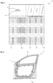
- a data set 16 relating to individual characteristics of a profile strand and thus of the sealing strands that can be separated from it is shown as an example.
- the data set 16 can, for example, be delivered to the customer in printed form together with the relevant profile strand/sealing strand.
- the data set 16 is made available to the customer in digital form, for example on a data carrier, in particular a data storage device (cloud storage) available via the Internet or a network.
- the relevant profile strand or the coil with the profile strand is marked with an identification means that enables it to be assigned to the data set 16.
- the data set 16 can have an identification number 18 in addition to a part number 17 of the customer.
- the data set 16 comprises a measurement value for various geometric and physical properties for a large number of sub-areas of the profile strand, which in this embodiment are each 1 m long.
- a time stamp relating to the production date/time is assigned in column 20
- a length measurement relating to the deviation of a second control point from a target value and a column 23 relating to the deviation of a friction value from a target value instead of one measured value per property and sub-area, however, several measured values can also be determined and the respective average value or min/max value can be stored in the data set.
- the measured values are preferably determined and stored online during the production of the profile strand.
- data set 16 is shown in abbreviated form; the complete data set contains the corresponding measured values for each meter of the sealing strip from meter 1 to meter 1000.
- the respective measured values change continuously over the length of the profile strip within the permissible tolerance, which may be related, for example, to the wear and tear of the machines used to produce the profile strip. The geometric deviations are greatest at the control points between the beginning and the end of the profile strip.
- an adjustment can also be made during application in such a way that the application device is adjusted during application of the sealing strips to the vehicle body depending on the corresponding physical and/or geometric properties in order to ensure that the seal on the vehicle body functions consistently.
- the function of the seal can have different focuses, for example, on the one hand, a design function can be in the foreground, which requires a consistent positioning of the seal, on the other hand, the focus can also be on the sealing function with as consistent closing properties as possible, as can be seen in the following figure.
- FIG. 6 a side view of a vehicle door 6 with a circumferential sealing strip 4 is shown.
- the sealing strip 4 completely seals the vehicle door 6 against the corresponding opening in the vehicle side wall (not shown).
- the sealing strip 4 has an upper section 24, which is easily visible due to its positioning on the top of the vehicle door 6, and a lower section 25, which is difficult to see due to its arrangement on the underside of the vehicle door 6 near the ground.
- the Application device or the application roller 7 can be adjusted in such a way that, despite the properties deviating from the target values over the length of the sealing strip 4, the sealing strip 4 in the upper section 24 has a constant position relative to the vehicle door 6, for example the position in Figure 4 shown distance 15 remains the same, and in the lower section 25 is displaced relative to the vehicle door 6 in such a way that a constant sealing effect, i.e. sealing function and closing force, is ensured.
- the sealing strip 4 in the lower section 25 the positioning in the upper section can be taken into account in particular, so that a certain closing force can be set for the entire vehicle door 6.
Landscapes
- Engineering & Computer Science (AREA)
- Mechanical Engineering (AREA)
- Seal Device For Vehicle (AREA)
- Automobile Manufacture Line, Endless Track Vehicle, Trailer (AREA)
Applications Claiming Priority (2)
| Application Number | Priority Date | Filing Date | Title |
|---|---|---|---|
| DE102019132555.2A DE102019132555A1 (de) | 2019-11-29 | 2019-11-29 | Dichtungsstrang mit individuellem Identifikationsmittel |
| PCT/EP2020/000180 WO2021104658A1 (de) | 2019-11-29 | 2020-10-28 | Dichtungsstrang mit individuellem identifikationsmittel und verfahren zur applikation |
Publications (2)
| Publication Number | Publication Date |
|---|---|
| EP4065396A1 EP4065396A1 (de) | 2022-10-05 |
| EP4065396B1 true EP4065396B1 (de) | 2024-06-19 |
Family
ID=73452154
Family Applications (1)
| Application Number | Title | Priority Date | Filing Date |
|---|---|---|---|
| EP20807663.8A Active EP4065396B1 (de) | 2019-11-29 | 2020-10-28 | Dichtungsstrang mit individuellem identifikationsmittel und verfahren zur applikation |
Country Status (5)
| Country | Link |
|---|---|
| EP (1) | EP4065396B1 (pl) |
| DE (1) | DE102019132555A1 (pl) |
| ES (1) | ES2988366T3 (pl) |
| PL (1) | PL4065396T3 (pl) |
| WO (1) | WO2021104658A1 (pl) |
Family Cites Families (6)
| Publication number | Priority date | Publication date | Assignee | Title |
|---|---|---|---|---|
| DE102005028069A1 (de) * | 2005-06-16 | 2006-05-11 | Sg Technologies Gmbh | Verfahren und Vorrichtung zur Bildung einer Dichtung oder Abdeckung an einem Dichtungs- bzw. Abdeckungsträger, insbesondere an einer Fahrzeugtür oder einem Karosserieausschnitt |
| DE102008037150A1 (de) * | 2008-08-08 | 2010-02-11 | Maschinenfabrik Niehoff Gmbh & Co Kg | Speichereinrichtung mit elektronischem Prozessorelement |
| DE102009016429A1 (de) * | 2009-04-04 | 2010-10-07 | Kempchen Dichtungstechnik Gmbh | Statische Flachdichtung |
| EP2426181B1 (en) * | 2010-09-03 | 2013-07-17 | 3M Innovative Properties Company | Method for applying elongate strip to door frame of vehicle |
| DE102014119222A1 (de) * | 2014-12-19 | 2016-06-23 | Cqlt Saargummi Technologies S.À.R.L. | Vorrichtung zur Aufnahme eines extrudierten Elastomerstrangs beim Transport zu einem Verarbeitungsort |
| KR102359944B1 (ko) * | 2017-09-22 | 2022-02-07 | 현대자동차 주식회사 | 웨더스트립의 부착 시스템 및 부착 방법 |
-
2019
- 2019-11-29 DE DE102019132555.2A patent/DE102019132555A1/de active Pending
-
2020
- 2020-10-28 WO PCT/EP2020/000180 patent/WO2021104658A1/de not_active Ceased
- 2020-10-28 EP EP20807663.8A patent/EP4065396B1/de active Active
- 2020-10-28 PL PL20807663.8T patent/PL4065396T3/pl unknown
- 2020-10-28 ES ES20807663T patent/ES2988366T3/es active Active
Also Published As
| Publication number | Publication date |
|---|---|
| WO2021104658A1 (de) | 2021-06-03 |
| DE102019132555A1 (de) | 2021-06-02 |
| ES2988366T3 (es) | 2024-11-20 |
| PL4065396T3 (pl) | 2024-11-04 |
| EP4065396A1 (de) | 2022-10-05 |
Similar Documents
| Publication | Publication Date | Title |
|---|---|---|
| EP0073056B1 (de) | Analyseteststreifen und Verfahren zu seiner Herstellung | |
| EP3679102B1 (de) | Verfahren und einrichtung zur herstellung eines klebebandes | |
| DE1435417A1 (de) | Vorrichtung und Verfahren zur Behandlung von Fasermaterial | |
| DE2830882A1 (de) | Verfahren zum strangpressen von kunstharz und strangpresswerkzeug zur durchfuehrung dieses verfahrens | |
| DE102011052821A1 (de) | Verfahren und Vorrichtung zur Herstellung eines Klebebandes | |
| EP4065396B1 (de) | Dichtungsstrang mit individuellem identifikationsmittel und verfahren zur applikation | |
| DE4225449A1 (de) | Extrusions-beschichtungsvorrichtung | |
| DE69624595T2 (de) | Drahtvorformlinge für verbundstoffherstellung und verfahren zu dessen herstellung | |
| DE102019110980A1 (de) | Planetenwälzgetriebe und Verfahren zur Montage eines Planetenwälzgetriebes | |
| EP3966123B1 (de) | Verpackung zum verpacken von verbrauchsmaterial und verfahren zum zuführen von verbrauchsmaterial | |
| AT4442U1 (de) | Vorrichtung zur bestimmung des betriebszustandes eines extruders zur erzeugung eines kunststoffprofils | |
| WO2007147751A1 (de) | Sortiereinrichtung sowie verfahren zum sortieren von rfid-etiketten | |
| DE69126684T2 (de) | Vorrichtung zum Positionieren eines Maskenbandes in einer Maschine zum Metallisieren | |
| AT525543B1 (de) | Lichtleiterfaserband und Verfahren zu dessen Herstellung | |
| EP1392455B1 (de) | Verfahren zum automatisierten auswählen von blechen, insbesondere stahlblechen, für das umformen zu bauelementen | |
| DE102008033413A1 (de) | Verfahren und Vorrichtung zur Herstellung eines aus plastischer Masse bestehenden kreiszylindrischen Körpers mit innenliegenden wendelförmigen Ausnehmungen | |
| DE102013200066A1 (de) | Wickelstation und Verfahren zu deren Betrieb | |
| EP3954527A1 (de) | Verfahren zur herstellung einer kunststoff-folie | |
| DE69412874T2 (de) | Herstellungsverfahren für den Verschluss einer Plattenkassette | |
| DE102019109640A1 (de) | Modulare Mehrwegwickelhülse | |
| EP0279173A2 (de) | Vorrichtung zur Messung kleiner Dickenprofiländerungen in bandförmigem Material, insbesondere fotografischem Basispapier | |
| DE3873187T2 (de) | Methode und vorrichtung zum leimen eines werkstueckes mit profil. | |
| DE102009026271A1 (de) | Kennzeichnungssystem für Wickelgüter und Verfahren zu dessen Herstellung | |
| DE202011108659U1 (de) | Messeranordnung | |
| EP1231036A2 (de) | Vorrichtung zum Abtrennen von streifen- oder bandförmigen Materialien in Montagemaschinen |
Legal Events
| Date | Code | Title | Description |
|---|---|---|---|
| STAA | Information on the status of an ep patent application or granted ep patent |
Free format text: STATUS: UNKNOWN |
|
| STAA | Information on the status of an ep patent application or granted ep patent |
Free format text: STATUS: THE INTERNATIONAL PUBLICATION HAS BEEN MADE |
|
| PUAI | Public reference made under article 153(3) epc to a published international application that has entered the european phase |
Free format text: ORIGINAL CODE: 0009012 |
|
| STAA | Information on the status of an ep patent application or granted ep patent |
Free format text: STATUS: REQUEST FOR EXAMINATION WAS MADE |
|
| 17P | Request for examination filed |
Effective date: 20220329 |
|
| AK | Designated contracting states |
Kind code of ref document: A1 Designated state(s): AL AT BE BG CH CY CZ DE DK EE ES FI FR GB GR HR HU IE IS IT LI LT LU LV MC MK MT NL NO PL PT RO RS SE SI SK SM TR |
|
| DAV | Request for validation of the european patent (deleted) | ||
| DAX | Request for extension of the european patent (deleted) | ||
| GRAP | Despatch of communication of intention to grant a patent |
Free format text: ORIGINAL CODE: EPIDOSNIGR1 |
|
| STAA | Information on the status of an ep patent application or granted ep patent |
Free format text: STATUS: GRANT OF PATENT IS INTENDED |
|
| INTG | Intention to grant announced |
Effective date: 20240111 |
|
| GRAS | Grant fee paid |
Free format text: ORIGINAL CODE: EPIDOSNIGR3 |
|
| GRAA | (expected) grant |
Free format text: ORIGINAL CODE: 0009210 |
|
| STAA | Information on the status of an ep patent application or granted ep patent |
Free format text: STATUS: THE PATENT HAS BEEN GRANTED |
|
| AK | Designated contracting states |
Kind code of ref document: B1 Designated state(s): AL AT BE BG CH CY CZ DE DK EE ES FI FR GB GR HR HU IE IS IT LI LT LU LV MC MK MT NL NO PL PT RO RS SE SI SK SM TR |
|
| REG | Reference to a national code |
Ref country code: GB Ref legal event code: FG4D Free format text: NOT ENGLISH |
|
| REG | Reference to a national code |
Ref country code: CH Ref legal event code: EP |
|
| REG | Reference to a national code |
Ref country code: DE Ref legal event code: R096 Ref document number: 502020008335 Country of ref document: DE |
|
| PG25 | Lapsed in a contracting state [announced via postgrant information from national office to epo] |
Ref country code: BG Free format text: LAPSE BECAUSE OF FAILURE TO SUBMIT A TRANSLATION OF THE DESCRIPTION OR TO PAY THE FEE WITHIN THE PRESCRIBED TIME-LIMIT Effective date: 20240619 |
|
| PG25 | Lapsed in a contracting state [announced via postgrant information from national office to epo] |
Ref country code: HR Free format text: LAPSE BECAUSE OF FAILURE TO SUBMIT A TRANSLATION OF THE DESCRIPTION OR TO PAY THE FEE WITHIN THE PRESCRIBED TIME-LIMIT Effective date: 20240619 Ref country code: FI Free format text: LAPSE BECAUSE OF FAILURE TO SUBMIT A TRANSLATION OF THE DESCRIPTION OR TO PAY THE FEE WITHIN THE PRESCRIBED TIME-LIMIT Effective date: 20240619 |
|
| REG | Reference to a national code |
Ref country code: LT Ref legal event code: MG9D |
|
| PG25 | Lapsed in a contracting state [announced via postgrant information from national office to epo] |
Ref country code: GR Free format text: LAPSE BECAUSE OF FAILURE TO SUBMIT A TRANSLATION OF THE DESCRIPTION OR TO PAY THE FEE WITHIN THE PRESCRIBED TIME-LIMIT Effective date: 20240920 |
|
| REG | Reference to a national code |
Ref country code: NL Ref legal event code: MP Effective date: 20240619 |
|
| PG25 | Lapsed in a contracting state [announced via postgrant information from national office to epo] |
Ref country code: LV Free format text: LAPSE BECAUSE OF FAILURE TO SUBMIT A TRANSLATION OF THE DESCRIPTION OR TO PAY THE FEE WITHIN THE PRESCRIBED TIME-LIMIT Effective date: 20240619 |
|
| PG25 | Lapsed in a contracting state [announced via postgrant information from national office to epo] |
Ref country code: NO Free format text: LAPSE BECAUSE OF FAILURE TO SUBMIT A TRANSLATION OF THE DESCRIPTION OR TO PAY THE FEE WITHIN THE PRESCRIBED TIME-LIMIT Effective date: 20240919 Ref country code: LV Free format text: LAPSE BECAUSE OF FAILURE TO SUBMIT A TRANSLATION OF THE DESCRIPTION OR TO PAY THE FEE WITHIN THE PRESCRIBED TIME-LIMIT Effective date: 20240619 Ref country code: HR Free format text: LAPSE BECAUSE OF FAILURE TO SUBMIT A TRANSLATION OF THE DESCRIPTION OR TO PAY THE FEE WITHIN THE PRESCRIBED TIME-LIMIT Effective date: 20240619 Ref country code: GR Free format text: LAPSE BECAUSE OF FAILURE TO SUBMIT A TRANSLATION OF THE DESCRIPTION OR TO PAY THE FEE WITHIN THE PRESCRIBED TIME-LIMIT Effective date: 20240920 Ref country code: FI Free format text: LAPSE BECAUSE OF FAILURE TO SUBMIT A TRANSLATION OF THE DESCRIPTION OR TO PAY THE FEE WITHIN THE PRESCRIBED TIME-LIMIT Effective date: 20240619 Ref country code: BG Free format text: LAPSE BECAUSE OF FAILURE TO SUBMIT A TRANSLATION OF THE DESCRIPTION OR TO PAY THE FEE WITHIN THE PRESCRIBED TIME-LIMIT Effective date: 20240619 Ref country code: RS Free format text: LAPSE BECAUSE OF FAILURE TO SUBMIT A TRANSLATION OF THE DESCRIPTION OR TO PAY THE FEE WITHIN THE PRESCRIBED TIME-LIMIT Effective date: 20240919 |
|
| REG | Reference to a national code |
Ref country code: SK Ref legal event code: T3 Ref document number: E 44901 Country of ref document: SK |
|
| PG25 | Lapsed in a contracting state [announced via postgrant information from national office to epo] |
Ref country code: NL Free format text: LAPSE BECAUSE OF FAILURE TO SUBMIT A TRANSLATION OF THE DESCRIPTION OR TO PAY THE FEE WITHIN THE PRESCRIBED TIME-LIMIT Effective date: 20240619 |
|
| REG | Reference to a national code |
Ref country code: ES Ref legal event code: FG2A Ref document number: 2988366 Country of ref document: ES Kind code of ref document: T3 Effective date: 20241120 |
|
| PG25 | Lapsed in a contracting state [announced via postgrant information from national office to epo] |
Ref country code: NL Free format text: LAPSE BECAUSE OF FAILURE TO SUBMIT A TRANSLATION OF THE DESCRIPTION OR TO PAY THE FEE WITHIN THE PRESCRIBED TIME-LIMIT Effective date: 20240619 |
|
| PG25 | Lapsed in a contracting state [announced via postgrant information from national office to epo] |
Ref country code: PT Free format text: LAPSE BECAUSE OF FAILURE TO SUBMIT A TRANSLATION OF THE DESCRIPTION OR TO PAY THE FEE WITHIN THE PRESCRIBED TIME-LIMIT Effective date: 20241021 |
|
| PG25 | Lapsed in a contracting state [announced via postgrant information from national office to epo] |
Ref country code: PT Free format text: LAPSE BECAUSE OF FAILURE TO SUBMIT A TRANSLATION OF THE DESCRIPTION OR TO PAY THE FEE WITHIN THE PRESCRIBED TIME-LIMIT Effective date: 20241021 |
|
| PG25 | Lapsed in a contracting state [announced via postgrant information from national office to epo] |
Ref country code: EE Free format text: LAPSE BECAUSE OF FAILURE TO SUBMIT A TRANSLATION OF THE DESCRIPTION OR TO PAY THE FEE WITHIN THE PRESCRIBED TIME-LIMIT Effective date: 20240619 |
|
| PG25 | Lapsed in a contracting state [announced via postgrant information from national office to epo] |
Ref country code: IS Free format text: LAPSE BECAUSE OF FAILURE TO SUBMIT A TRANSLATION OF THE DESCRIPTION OR TO PAY THE FEE WITHIN THE PRESCRIBED TIME-LIMIT Effective date: 20241019 |
|
| PG25 | Lapsed in a contracting state [announced via postgrant information from national office to epo] |
Ref country code: RO Free format text: LAPSE BECAUSE OF FAILURE TO SUBMIT A TRANSLATION OF THE DESCRIPTION OR TO PAY THE FEE WITHIN THE PRESCRIBED TIME-LIMIT Effective date: 20240619 |
|
| PG25 | Lapsed in a contracting state [announced via postgrant information from national office to epo] |
Ref country code: SM Free format text: LAPSE BECAUSE OF FAILURE TO SUBMIT A TRANSLATION OF THE DESCRIPTION OR TO PAY THE FEE WITHIN THE PRESCRIBED TIME-LIMIT Effective date: 20240619 |
|
| PG25 | Lapsed in a contracting state [announced via postgrant information from national office to epo] |
Ref country code: SM Free format text: LAPSE BECAUSE OF FAILURE TO SUBMIT A TRANSLATION OF THE DESCRIPTION OR TO PAY THE FEE WITHIN THE PRESCRIBED TIME-LIMIT Effective date: 20240619 Ref country code: RO Free format text: LAPSE BECAUSE OF FAILURE TO SUBMIT A TRANSLATION OF THE DESCRIPTION OR TO PAY THE FEE WITHIN THE PRESCRIBED TIME-LIMIT Effective date: 20240619 Ref country code: IS Free format text: LAPSE BECAUSE OF FAILURE TO SUBMIT A TRANSLATION OF THE DESCRIPTION OR TO PAY THE FEE WITHIN THE PRESCRIBED TIME-LIMIT Effective date: 20241019 Ref country code: EE Free format text: LAPSE BECAUSE OF FAILURE TO SUBMIT A TRANSLATION OF THE DESCRIPTION OR TO PAY THE FEE WITHIN THE PRESCRIBED TIME-LIMIT Effective date: 20240619 |
|
| REG | Reference to a national code |
Ref country code: DE Ref legal event code: R097 Ref document number: 502020008335 Country of ref document: DE |
|
| PG25 | Lapsed in a contracting state [announced via postgrant information from national office to epo] |
Ref country code: DK Free format text: LAPSE BECAUSE OF FAILURE TO SUBMIT A TRANSLATION OF THE DESCRIPTION OR TO PAY THE FEE WITHIN THE PRESCRIBED TIME-LIMIT Effective date: 20240619 |
|
| PLBE | No opposition filed within time limit |
Free format text: ORIGINAL CODE: 0009261 |
|
| STAA | Information on the status of an ep patent application or granted ep patent |
Free format text: STATUS: NO OPPOSITION FILED WITHIN TIME LIMIT |
|
| 26N | No opposition filed |
Effective date: 20250320 |
|
| REG | Reference to a national code |
Ref country code: CH Ref legal event code: PL |
|
| GBPC | Gb: european patent ceased through non-payment of renewal fee |
Effective date: 20241028 |
|
| PG25 | Lapsed in a contracting state [announced via postgrant information from national office to epo] |
Ref country code: MC Free format text: LAPSE BECAUSE OF FAILURE TO SUBMIT A TRANSLATION OF THE DESCRIPTION OR TO PAY THE FEE WITHIN THE PRESCRIBED TIME-LIMIT Effective date: 20240619 |
|
| PG25 | Lapsed in a contracting state [announced via postgrant information from national office to epo] |
Ref country code: GB Free format text: LAPSE BECAUSE OF NON-PAYMENT OF DUE FEES Effective date: 20241028 |
|
| PG25 | Lapsed in a contracting state [announced via postgrant information from national office to epo] |
Ref country code: LU Free format text: LAPSE BECAUSE OF NON-PAYMENT OF DUE FEES Effective date: 20241028 Ref country code: BE Free format text: LAPSE BECAUSE OF NON-PAYMENT OF DUE FEES Effective date: 20241031 |
|
| PG25 | Lapsed in a contracting state [announced via postgrant information from national office to epo] |
Ref country code: CH Free format text: LAPSE BECAUSE OF NON-PAYMENT OF DUE FEES Effective date: 20241031 |
|
| REG | Reference to a national code |
Ref country code: BE Ref legal event code: MM Effective date: 20241031 |
|
| PG25 | Lapsed in a contracting state [announced via postgrant information from national office to epo] |
Ref country code: SE Free format text: LAPSE BECAUSE OF FAILURE TO SUBMIT A TRANSLATION OF THE DESCRIPTION OR TO PAY THE FEE WITHIN THE PRESCRIBED TIME-LIMIT Effective date: 20240619 |
|
| PG25 | Lapsed in a contracting state [announced via postgrant information from national office to epo] |
Ref country code: IE Free format text: LAPSE BECAUSE OF NON-PAYMENT OF DUE FEES Effective date: 20241028 |
|
| PGFP | Annual fee paid to national office [announced via postgrant information from national office to epo] |
Ref country code: DE Payment date: 20251021 Year of fee payment: 6 |
|
| PGFP | Annual fee paid to national office [announced via postgrant information from national office to epo] |
Ref country code: AT Payment date: 20260113 Year of fee payment: 5 |
|
| PGFP | Annual fee paid to national office [announced via postgrant information from national office to epo] |
Ref country code: IT Payment date: 20251024 Year of fee payment: 6 |
|
| PGFP | Annual fee paid to national office [announced via postgrant information from national office to epo] |
Ref country code: FR Payment date: 20251030 Year of fee payment: 6 |
|
| PGFP | Annual fee paid to national office [announced via postgrant information from national office to epo] |
Ref country code: CZ Payment date: 20251021 Year of fee payment: 6 |
|
| PGFP | Annual fee paid to national office [announced via postgrant information from national office to epo] |
Ref country code: PL Payment date: 20251016 Year of fee payment: 6 |
|
| PGFP | Annual fee paid to national office [announced via postgrant information from national office to epo] |
Ref country code: SK Payment date: 20251020 Year of fee payment: 6 |
|
| PGFP | Annual fee paid to national office [announced via postgrant information from national office to epo] |
Ref country code: ES Payment date: 20251216 Year of fee payment: 6 |
|
| PG25 | Lapsed in a contracting state [announced via postgrant information from national office to epo] |
Ref country code: HU Free format text: LAPSE BECAUSE OF FAILURE TO SUBMIT A TRANSLATION OF THE DESCRIPTION OR TO PAY THE FEE WITHIN THE PRESCRIBED TIME-LIMIT; INVALID AB INITIO Effective date: 20201028 |
|
| PG25 | Lapsed in a contracting state [announced via postgrant information from national office to epo] |
Ref country code: CY Free format text: LAPSE BECAUSE OF FAILURE TO SUBMIT A TRANSLATION OF THE DESCRIPTION OR TO PAY THE FEE WITHIN THE PRESCRIBED TIME-LIMIT; INVALID AB INITIO Effective date: 20201028 |