EP4065263B1 - Mischwerkzeug zum trockenmischen und coaten - Google Patents
Mischwerkzeug zum trockenmischen und coaten Download PDFInfo
- Publication number
- EP4065263B1 EP4065263B1 EP20816429.3A EP20816429A EP4065263B1 EP 4065263 B1 EP4065263 B1 EP 4065263B1 EP 20816429 A EP20816429 A EP 20816429A EP 4065263 B1 EP4065263 B1 EP 4065263B1
- Authority
- EP
- European Patent Office
- Prior art keywords
- tool
- whirling
- groove
- wear
- container
- Prior art date
- Legal status (The legal status is an assumption and is not a legal conclusion. Google has not performed a legal analysis and makes no representation as to the accuracy of the status listed.)
- Active
Links
Images


Classifications
-
- B—PERFORMING OPERATIONS; TRANSPORTING
- B01—PHYSICAL OR CHEMICAL PROCESSES OR APPARATUS IN GENERAL
- B01F—MIXING, e.g. DISSOLVING, EMULSIFYING OR DISPERSING
- B01F27/00—Mixers with rotary stirring devices in fixed receptacles; Kneaders
- B01F27/05—Stirrers
- B01F27/051—Stirrers characterised by their elements, materials or mechanical properties
- B01F27/052—Stirrers with replaceable wearing elements; Wearing elements therefor
-
- B—PERFORMING OPERATIONS; TRANSPORTING
- B01—PHYSICAL OR CHEMICAL PROCESSES OR APPARATUS IN GENERAL
- B01F—MIXING, e.g. DISSOLVING, EMULSIFYING OR DISPERSING
- B01F27/00—Mixers with rotary stirring devices in fixed receptacles; Kneaders
- B01F27/05—Stirrers
- B01F27/11—Stirrers characterised by the configuration of the stirrers
- B01F27/115—Stirrers characterised by the configuration of the stirrers comprising discs or disc-like elements essentially perpendicular to the stirrer shaft axis
- B01F27/1152—Stirrers characterised by the configuration of the stirrers comprising discs or disc-like elements essentially perpendicular to the stirrer shaft axis with separate elements other than discs fixed on the discs, e.g. vanes fixed on the discs
-
- B—PERFORMING OPERATIONS; TRANSPORTING
- B01—PHYSICAL OR CHEMICAL PROCESSES OR APPARATUS IN GENERAL
- B01J—CHEMICAL OR PHYSICAL PROCESSES, e.g. CATALYSIS OR COLLOID CHEMISTRY; THEIR RELEVANT APPARATUS
- B01J2/00—Processes or devices for granulating materials, e.g. fertilisers in general; Rendering particulate materials free flowing in general, e.g. making them hydrophobic
- B01J2/10—Processes or devices for granulating materials, e.g. fertilisers in general; Rendering particulate materials free flowing in general, e.g. making them hydrophobic in stationary drums or troughs, provided with kneading or mixing appliances
-
- B—PERFORMING OPERATIONS; TRANSPORTING
- B01—PHYSICAL OR CHEMICAL PROCESSES OR APPARATUS IN GENERAL
- B01F—MIXING, e.g. DISSOLVING, EMULSIFYING OR DISPERSING
- B01F23/00—Mixing according to the phases to be mixed, e.g. dispersing or emulsifying
- B01F23/60—Mixing solids with solids
-
- B—PERFORMING OPERATIONS; TRANSPORTING
- B01—PHYSICAL OR CHEMICAL PROCESSES OR APPARATUS IN GENERAL
- B01F—MIXING, e.g. DISSOLVING, EMULSIFYING OR DISPERSING
- B01F27/00—Mixers with rotary stirring devices in fixed receptacles; Kneaders
- B01F27/05—Stirrers
- B01F27/051—Stirrers characterised by their elements, materials or mechanical properties
- B01F27/053—Stirrers characterised by their elements, materials or mechanical properties characterised by their materials
-
- B—PERFORMING OPERATIONS; TRANSPORTING
- B01—PHYSICAL OR CHEMICAL PROCESSES OR APPARATUS IN GENERAL
- B01F—MIXING, e.g. DISSOLVING, EMULSIFYING OR DISPERSING
- B01F29/00—Mixers with rotating receptacles
- B01F29/80—Mixers with rotating receptacles rotating about a substantially vertical axis
- B01F29/86—Mixers with rotating receptacles rotating about a substantially vertical axis with rotary discs
-
- B—PERFORMING OPERATIONS; TRANSPORTING
- B01—PHYSICAL OR CHEMICAL PROCESSES OR APPARATUS IN GENERAL
- B01J—CHEMICAL OR PHYSICAL PROCESSES, e.g. CATALYSIS OR COLLOID CHEMISTRY; THEIR RELEVANT APPARATUS
- B01J2/00—Processes or devices for granulating materials, e.g. fertilisers in general; Rendering particulate materials free flowing in general, e.g. making them hydrophobic
- B01J2/006—Coating of the granules without description of the process or the device by which the granules are obtained
-
- Y—GENERAL TAGGING OF NEW TECHNOLOGICAL DEVELOPMENTS; GENERAL TAGGING OF CROSS-SECTIONAL TECHNOLOGIES SPANNING OVER SEVERAL SECTIONS OF THE IPC; TECHNICAL SUBJECTS COVERED BY FORMER USPC CROSS-REFERENCE ART COLLECTIONS [XRACs] AND DIGESTS
- Y02—TECHNOLOGIES OR APPLICATIONS FOR MITIGATION OR ADAPTATION AGAINST CLIMATE CHANGE
- Y02E—REDUCTION OF GREENHOUSE GAS [GHG] EMISSIONS, RELATED TO ENERGY GENERATION, TRANSMISSION OR DISTRIBUTION
- Y02E60/00—Enabling technologies; Technologies with a potential or indirect contribution to GHG emissions mitigation
- Y02E60/10—Energy storage using batteries
Definitions
- the present invention relates to a tool for dry mixing and coating powder mixtures. Dry mixing involves mixing several dry and often powdered materials together. During coating, coarser powder particles can be coated by dry mixing while simultaneously depositing significantly finer particles on the surface of the coarser particles. Alternatively or in combination with the fine particles, liquids can be applied in very small quantities to the coarser powder, which wet the particle surface as completely as possible.
- Whirling tools for intensive mixers for the microgranulation of moist solid mixtures which has a fastening shaft and an approximately disk-shaped element attached thereto with a diameter d, with an upper surface, a lower surface and a peripheral surface connecting the upper and lower surfaces, the Circumferential surface has a plurality of grooves running parallel to the shaft axis, each groove having two groove walls extending from the circumferential surface to a groove base, so that a tooth is formed between two adjacent grooves.
- circumferential surface is to be understood here to mean that the groove walls and the groove base are not part of the circumferential surface.
- the peripheral surface is therefore interrupted by the grooves introduced. If the disk-shaped element is exactly circular, the peripheral surface lies on the circumference of the disk-shaped element.
- the direction of rotation of the tool is fixed. Therefore, the groove wall leading in the direction of rotation is provided with a hard metal element in order to reduce wear on the tool, especially at the radially outer end.
- the known tool is therefore fundamentally unsuitable for dry mixing and coating of powder mixtures, especially if this is to be carried out as iron-free as possible, since due to the structure it cannot be prevented that abrasion from the tool made of iron gets into the mix, which is essential for contamination-free dry mixing is to be avoided.
- any contamination of the mixed material for example through tool abrasion, must be avoided.
- the WO 2012/123441 A1 discloses a tool according to the preamble of claim 1.
- a device for deagglomerating powder in a mixture of liquid and powder contains a mixing container, a stirring disk arranged in the mixing container and a baffle plate.
- the disc contains a plurality of composite teeth mounted radially and removably around its circumference.
- Each of the composite teeth consists of a substrate to which is attached a faceplate, preferably made of a ceramic material such as tungsten carbide.
- a wear element which is aligned in the direction of rotation, but also the opposite groove wall and, ideally, also the peripheral surface at the radially outer end of the teeth. Tests have shown that abrasion occurs predominantly on the sections of the groove wall that adjoin the peripheral surface.
- each tooth it is also possible for the entire tooth or even a group of teeth to be designed as a wear element. It is also possible to equip each tooth with a wear protection cap that covers the tooth.
- each groove wall adjacent to the peripheral surface is formed by the at least one wear element.
- a number of wear elements can therefore be provided in a groove, which form at least sections of opposing groove walls, or entire groups of teeth or even just individual teeth can be designed as wear elements. In any case, it is ensured that at least a section of each groove wall adjacent to the peripheral surface is made of a wear-resistant material.
- a wear-resistant material is understood to mean any material that has increased wear resistance compared to the material of the base body.
- the embodiment according to the invention also has the advantage that the direction of rotation of the tool can be changed during operation in order to achieve operation with as little dust as possible.
- the wear element preferably consists of hard metal.
- other wear-resistant non-ferrous materials such as ceramic, can also be used with advantage.
- both groove walls and preferably also the groove base are formed by the at least one wear element.
- the at least one wear element not only the section of the groove wall adjacent to the peripheral surface is equipped with or is formed by a wear element, but the entire groove wall and preferably also the groove base.
- the peripheral surface between two grooves could also be equipped with or formed by a wear element. This can further reduce abrasion.
- the wear element is designed in several parts.
- the groove base has a groove base length extending from the first groove wall to the second groove wall, which is at least 10%, preferably at least 25% of the groove wall length from the groove base to the peripheral surface.
- At least 20%, preferably at least 50%, of the groove wall length should be formed by the at least one wear element.
- V-shaped grooves shown have the disadvantage during dry mixing that, under certain circumstances, mix components, especially in the case of cohesive raw materials, accumulate near the bottom of the groove and no longer take part in the mixing process. Due to the described design of the groove base, the groove is made significantly larger, particularly in the area of the groove base, so that the risk of mix components getting stuck in the groove base is significantly reduced.
- the grooves should not be too small to ensure effective mixing.
- the groove wall has a groove wall length extending from the peripheral surface to the groove base, which is between 0.05 and 0.4 times, preferably between 0.1 and 0.3 times and most preferably between 0. 15 and 0.25 times the diameter d of the disc-shaped element.
- the lower surface has at least one whirling element which protrudes beyond the lower surface, preferably several whirling elements being provided which particularly preferably have the same angular distances in the circumferential direction.
- the whirling elements push the mix that gets under the disc outwards and upwards so that it can flow upwards into the grooves. This prevents mix components from settling on the bottom of the container in which the tool is used and no longer taking part in the mixing process.
- the whirling element preferably consists of a wear-resistant material, such as hard metal or ceramic.
- the whirling element could also consist of a hardened metal, such as hardened steel.
- At least one whirling element can be moved back and forth between two positions, with the whirling element protruding less far beyond the lower surface in the first position than in the second position.
- the whirling element can be fastened at least in the second position in such a way that no unintentional movement of the whirling element takes place between the first and second positions during operation of the tool.
- the length of the whirling element can be adjustable, so that the adjustment of the length results in a movement between the first and the second position.
- the length with which the whirling element protrudes in the axial direction over the lower surface of the disc-shaped element can also be achieved by screwing the whirling element to the disc-shaped element and using one or more washers to change this length between the whirling element and the disc-shaped element to be ordered.
- This measure makes it possible to arrange this whirling element as close as possible to the surface of the container in which the tool is arranged.
- the distance between the lower edge of the whirling element and the upper edge of the container base is preferably only a few 1/10 of a millimeter to a few millimeters, preferably between 0.2 mm and 5 mm. The remaining whirling elements can then be at a significantly greater distance from the surface of the container bottom.
- the whirling element has a threaded hole into which a screw gripping through a through hole in the disc-shaped element engages in order to fasten the whirling element. If the tool is to be moved axially towards the bottom of the container, the axially more protruding whirling elements must be detached from the disk-shaped element and removed in the radial direction.
- the whirling element is also formed by the wear element.
- a wear element could consist of a group of teeth and an integrally formed, e.g. soldered, whirling element.
- the whirling element is arranged closer to the fastening shaft than the groove base, with the distance between the fastening shaft and the whirling element preferably being >50%, preferably >75% and best between 80 and 98% of the distance between the groove base and the fastening shaft.
- the present invention also relates to a device for dry mixing or coating powder mixtures with a container and a tool according to the invention arranged therein.
- the container is rotatable about a container axis which is spaced from the fastening shaft axis, the diameter d of the disk-shaped element preferably being between 30 and 70% of the container diameter.
- the tool is positioned within the container in such a way that the smallest distance between the peripheral surface of the tool and the container wall is less than 10% of the container diameter.
- Figure 1 a perspective view of a first embodiment of the invention is shown.
- the tool 1 has a fastening shaft 2 with a flange 3.
- the tool can be attached to a drive (not shown) via the flange 3 and rotated about the axis of the attachment shaft 2.
- a disk-shaped element 4 is arranged, the disk axis of which coincides with the axis of the fastening shaft 2.
- the disc-shaped element has an upper surface which is in Figure 1 can be seen, a lower surface that is in Figure 1 cannot be seen and a peripheral surface connecting the upper and lower surfaces.
- the disk-shaped element has a plurality of teeth 5, which are formed by grooves running parallel to the shaft axis. By introducing the grooves into the disk-shaped element, the teeth 5 remain between the grooves.
- both groove walls are covered with a wear element 6 made of hard metal.
- three parts of the wear element 6 are attached to each groove wall.
- the radially outer wear element parts are arranged on the section of the groove wall which adjoins the peripheral surface. All other wear elements on a groove wall preferably adjoin directly to the groove base, the wear element part positioned radially further out.
- the groove base 7 is not covered with the wear element.
- a wear-resistant layer can be created by, for example, surface hardening or can be created using a coating.
- the coating can consist of a plastic, such as polyurethane, or of a surface hardening. A spray coating with which a ceramic or a hard metal is coated is particularly preferred.
- the layer thickness of the spray coating should, if possible, be at least 0.1 mm and particularly preferably more than 0.4 mm.
- the surface roughness of the coating is chosen such that a layer of the product that is a few particle layers thick adheres, which protects the tool from abrasion and thus wear.
- whirling elements 8 and 8 ' are arranged, which protrude beyond the lower surface.
- a whirling element 8 is height-adjustable, i.e. it is designed in such a way that it can be moved back and forth between two positions or adjusted in length, with the whirling element 8 protruding less far beyond the lower surface in the first position like in the second position.
- the Figure 2 shows a close-up view of the disc-shaped element with whirling elements according to Figure 1 .
- the whirling element 8 is attached to the disc-shaped element 4 via a releasable screw connection 12.
- one or more washers 11 are inserted between the whirling element 8 and the disc-shaped element 4. If the manufacturing tolerances are very small, the washers can be dispensed with completely.
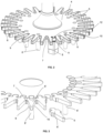
- Figure 3 shows a perspective view from above of the tool while Figure 4 a view from below of the tool.
- FIG 3 shows a variant of the invention in which the wear element 6 'consists of individual teeth, which are, for example, made entirely of ceramic.
- the wear elements 6' are suspended in a form-fitting manner in corresponding recesses in the base plate via a pin at one end of the wear element, so that they cannot move in the radial direction.
- a vertical movement of the wear element in the recess can be prevented, for example, by a circular or annular cover plate on the top and bottom of the base plate, which partially or completely covers the recess.
- the end of the wear element opposite the pin is the tooth 5 with the groove walls 9 and 10 and the groove base 7.
- the whirling elements 8 ' can be attached to the wear elements 6'.
- the wear element here consists of a large number of wear element parts 6 ', which in turn each form seven teeth 5 of the tool.
- a wear element for example made of hard metal, but the entire tooth, ie the entire wear element part 6 'is made here of, for example, hard metal.
- the lower surface of the essentially disk-shaped element can be seen. It can also be seen that the whirling elements 8 'are attached to the wear element parts 6'.
Landscapes
- Chemical & Material Sciences (AREA)
- Chemical Kinetics & Catalysis (AREA)
- Organic Chemistry (AREA)
- Crushing And Grinding (AREA)
- Mixers Of The Rotary Stirring Type (AREA)
- Paints Or Removers (AREA)
- Mixers With Rotating Receptacles And Mixers With Vibration Mechanisms (AREA)
Applications Claiming Priority (2)
| Application Number | Priority Date | Filing Date | Title |
|---|---|---|---|
| DE102019132264.2A DE102019132264A1 (de) | 2019-11-28 | 2019-11-28 | Mischwerkzeug zum Trockenmischen und Coaten |
| PCT/EP2020/083521 WO2021105291A1 (de) | 2019-11-28 | 2020-11-26 | Mischwerkzeug zum trockenmischen und coaten |
Publications (3)
| Publication Number | Publication Date |
|---|---|
| EP4065263A1 EP4065263A1 (de) | 2022-10-05 |
| EP4065263B1 true EP4065263B1 (de) | 2023-09-13 |
| EP4065263C0 EP4065263C0 (de) | 2023-09-13 |
Family
ID=73646309
Family Applications (1)
| Application Number | Title | Priority Date | Filing Date |
|---|---|---|---|
| EP20816429.3A Active EP4065263B1 (de) | 2019-11-28 | 2020-11-26 | Mischwerkzeug zum trockenmischen und coaten |
Country Status (10)
| Country | Link |
|---|---|
| US (1) | US12447447B2 (pl) |
| EP (1) | EP4065263B1 (pl) |
| JP (1) | JP2023507903A (pl) |
| KR (1) | KR20220108093A (pl) |
| CN (2) | CN212595056U (pl) |
| BR (1) | BR112022004247A2 (pl) |
| DE (1) | DE102019132264A1 (pl) |
| ES (1) | ES2962928T3 (pl) |
| PL (1) | PL4065263T3 (pl) |
| WO (1) | WO2021105291A1 (pl) |
Families Citing this family (2)
| Publication number | Priority date | Publication date | Assignee | Title |
|---|---|---|---|---|
| DE102019132264A1 (de) | 2019-11-28 | 2021-06-02 | Maschinenfabrik Gustav Eirich Gmbh & Co. Kg | Mischwerkzeug zum Trockenmischen und Coaten |
| KR20250141287A (ko) * | 2024-03-19 | 2025-09-29 | 삼성에스디아이 주식회사 | 이차전지 전극 소재 혼합 교반 장치 및 그 제어방법 |
Family Cites Families (19)
| Publication number | Priority date | Publication date | Assignee | Title |
|---|---|---|---|---|
| LU39997A1 (pl) | 1961-04-10 | |||
| US3630636A (en) * | 1970-04-22 | 1971-12-28 | Continental Oil Co | Blade apparatus for high-shear mixing |
| FR2229464A1 (en) | 1973-05-17 | 1974-12-13 | Euro Machines | Mixer-grinder for solid-liquid dispersions - with eccentric turbine mixer and scraper blade eliminating dead zones |
| US4153377A (en) * | 1977-10-25 | 1979-05-08 | Been Jr Lars J | Apparatus for and method of dissolving a solid in a liquid |
| US5409313A (en) | 1993-01-12 | 1995-04-25 | Funk; James E. | Apparatus for high shear mixing of fine powders |
| US5292193A (en) | 1993-01-12 | 1994-03-08 | Funk James E | Apparatus for the high intensity dispersion of agglomerated powders in crowded suspensions having an agitator disk |
| WO1995031276A1 (en) * | 1994-05-16 | 1995-11-23 | Niro A/S | Compacting granulator |
| US5947599A (en) * | 1998-11-25 | 1999-09-07 | Funk; James E. | Continuous high intensity disperser with agitator disks |
| US20040234677A1 (en) * | 1999-08-12 | 2004-11-25 | Nisshinbo Industries, Inc. | Mixer for coating an ion-conducting polymer on a powdered substance and method for coating the same |
| EP1960108B1 (de) * | 2005-12-08 | 2018-01-10 | swissRTec AG | Rotor für eine prallmühle |
| DE202008006745U1 (de) | 2008-05-19 | 2008-07-31 | Doceram Gmbh | Mahlscheibe |
| DE102011005519A1 (de) | 2011-03-14 | 2012-09-20 | Maschinenfabrik Gustav Eirich Gmbh & Co. Kg | Verfahren zum Granulieren oder Agglomerieren sowie Werkzeug hierfür |
| JP6238434B2 (ja) * | 2013-08-23 | 2017-11-29 | 三菱マテリアルテクノ株式会社 | ディスク構造、ディスク用プロテクタ及びディスク型処理装置 |
| CN205146327U (zh) | 2015-05-23 | 2016-04-13 | 石汉强 | 一种陶瓷机械磨粉装置 |
| JP2020514971A (ja) * | 2016-12-23 | 2020-05-21 | ポスコPosco | 二次電池用正極活物質製造方法および二次電池用活物質製造装置 |
| JP6874440B2 (ja) * | 2017-03-15 | 2021-05-19 | 住友金属鉱山株式会社 | 撹拌翼 |
| CN109499720A (zh) | 2018-11-05 | 2019-03-22 | 丽水市正明机械科技有限公司 | 一种基于旋转研磨分散原理的涂料加工设备 |
| KR101981131B1 (ko) | 2019-03-15 | 2019-05-22 | (주)티에스아이 | 전지 전극용 슬러리 믹서 |
| DE102019132264A1 (de) | 2019-11-28 | 2021-06-02 | Maschinenfabrik Gustav Eirich Gmbh & Co. Kg | Mischwerkzeug zum Trockenmischen und Coaten |
-
2019
- 2019-11-28 DE DE102019132264.2A patent/DE102019132264A1/de not_active Withdrawn
-
2020
- 2020-03-03 CN CN202020247003.6U patent/CN212595056U/zh active Active
- 2020-11-26 PL PL20816429.3T patent/PL4065263T3/pl unknown
- 2020-11-26 WO PCT/EP2020/083521 patent/WO2021105291A1/de not_active Ceased
- 2020-11-26 ES ES20816429T patent/ES2962928T3/es active Active
- 2020-11-26 EP EP20816429.3A patent/EP4065263B1/de active Active
- 2020-11-26 US US17/780,159 patent/US12447447B2/en active Active
- 2020-11-26 JP JP2022531628A patent/JP2023507903A/ja active Pending
- 2020-11-26 BR BR112022004247A patent/BR112022004247A2/pt active IP Right Grant
- 2020-11-26 KR KR1020227021388A patent/KR20220108093A/ko not_active Ceased
- 2020-11-26 CN CN202080080054.7A patent/CN114728245B/zh active Active
Also Published As
| Publication number | Publication date |
|---|---|
| PL4065263T3 (pl) | 2024-02-26 |
| EP4065263A1 (de) | 2022-10-05 |
| JP2023507903A (ja) | 2023-02-28 |
| DE102019132264A1 (de) | 2021-06-02 |
| CN114728245B (zh) | 2024-11-19 |
| CN212595056U (zh) | 2021-02-26 |
| US20220410095A1 (en) | 2022-12-29 |
| CN114728245A (zh) | 2022-07-08 |
| WO2021105291A1 (de) | 2021-06-03 |
| US12447447B2 (en) | 2025-10-21 |
| ES2962928T3 (es) | 2024-03-21 |
| BR112022004247A2 (pt) | 2022-06-21 |
| KR20220108093A (ko) | 2022-08-02 |
| EP4065263C0 (de) | 2023-09-13 |
Similar Documents
| Publication | Publication Date | Title |
|---|---|---|
| DE2925704C2 (de) | Industrielles Dispergiergerät | |
| DE4401384C2 (de) | Rührwerksmühle | |
| DE102012100976B4 (de) | Einschraubwerkzeug und Werkzeugaufnahme für ein derartiges Einschraubwerkzeug | |
| EP2189221B1 (de) | Rührwerkskugelmühle | |
| EP2558191B1 (de) | MISCHVORRICHTUNG MIT VERSCHLEIßSCHUTZAUSKLEIDUNG | |
| EP4065263B1 (de) | Mischwerkzeug zum trockenmischen und coaten | |
| DE8910604U1 (de) | Spindelmutteranordnung | |
| EP3840620B1 (de) | Mahlwerk zum mahlen von mahlgut | |
| EP2551054A2 (de) | Anordnung zum Schleifen von Elektroden | |
| DE4338903A1 (de) | Zerkleinerungsmaschine und Einrichtung zur Einstellung des Spaltes einer solchen Zerkleinerungsmaschine | |
| EP2686093A1 (de) | Verfahren zum granulieren oder agglomerieren sowie werkzeug hierfür | |
| DE2361123C2 (de) | Zerstäuberrad zum Zerstäuben von Aufschlämmungen stark verschleißend wirkenden Materialien | |
| EP2364770B1 (de) | Werkzeug für Mischvorrichtung | |
| EP0063627A1 (de) | Mischbatterie | |
| DE102013003110B4 (de) | Schmierdüse | |
| DE2644992A1 (de) | Fraesvorrichtung, insbesondere zum abfraesen von strassenbelaegen | |
| EP3958717B1 (de) | Mahlwerk mit blockierelement | |
| DE60104494T2 (de) | Zerstäuberrad mit verschleissbeständigen Einsätzen | |
| WO2010142520A1 (de) | Schleif- und/oder polierwerkzeug und herstellungsverfahren | |
| EP0410229B1 (de) | Rührwerkmühle zur Feinstmahlung | |
| DE102006052904B4 (de) | Anordnung zum Schleifen von Elektroden | |
| DE2444151C2 (de) | Getreidemühle als Zusatzgerät für eine Küchenmaschine | |
| DE69108731T2 (de) | Zerstäuberrad. | |
| EP1782917A1 (de) | Aufnahme für ein Schleifwerkzeug, Schleifwerkzeug und Tragkörper für ein Schleifwerkzeug | |
| DE4422295C2 (de) | Abstreifer |
Legal Events
| Date | Code | Title | Description |
|---|---|---|---|
| STAA | Information on the status of an ep patent application or granted ep patent |
Free format text: STATUS: UNKNOWN |
|
| STAA | Information on the status of an ep patent application or granted ep patent |
Free format text: STATUS: THE INTERNATIONAL PUBLICATION HAS BEEN MADE |
|
| PUAI | Public reference made under article 153(3) epc to a published international application that has entered the european phase |
Free format text: ORIGINAL CODE: 0009012 |
|
| STAA | Information on the status of an ep patent application or granted ep patent |
Free format text: STATUS: REQUEST FOR EXAMINATION WAS MADE |
|
| 17P | Request for examination filed |
Effective date: 20220530 |
|
| AK | Designated contracting states |
Kind code of ref document: A1 Designated state(s): AL AT BE BG CH CY CZ DE DK EE ES FI FR GB GR HR HU IE IS IT LI LT LU LV MC MK MT NL NO PL PT RO RS SE SI SK SM TR |
|
| DAV | Request for validation of the european patent (deleted) | ||
| DAX | Request for extension of the european patent (deleted) | ||
| REG | Reference to a national code |
Ref country code: DE Ref legal event code: R079 Free format text: PREVIOUS MAIN CLASS: B01F0007000000 Ipc: B01F0027052000 Ref country code: DE Ref legal event code: R079 Ref document number: 502020005268 Country of ref document: DE Free format text: PREVIOUS MAIN CLASS: B01F0007000000 Ipc: B01F0027052000 |
|
| GRAP | Despatch of communication of intention to grant a patent |
Free format text: ORIGINAL CODE: EPIDOSNIGR1 |
|
| STAA | Information on the status of an ep patent application or granted ep patent |
Free format text: STATUS: GRANT OF PATENT IS INTENDED |
|
| RIC1 | Information provided on ipc code assigned before grant |
Ipc: B01J 2/10 20060101ALI20230403BHEP Ipc: B01J 2/00 20060101ALI20230403BHEP Ipc: B01F 29/86 20220101ALI20230403BHEP Ipc: B01F 27/1152 20220101ALI20230403BHEP Ipc: B01F 27/053 20220101ALI20230403BHEP Ipc: B01F 27/052 20220101AFI20230403BHEP |
|
| INTG | Intention to grant announced |
Effective date: 20230424 |
|
| GRAS | Grant fee paid |
Free format text: ORIGINAL CODE: EPIDOSNIGR3 |
|
| GRAA | (expected) grant |
Free format text: ORIGINAL CODE: 0009210 |
|
| STAA | Information on the status of an ep patent application or granted ep patent |
Free format text: STATUS: THE PATENT HAS BEEN GRANTED |
|
| AK | Designated contracting states |
Kind code of ref document: B1 Designated state(s): AL AT BE BG CH CY CZ DE DK EE ES FI FR GB GR HR HU IE IS IT LI LT LU LV MC MK MT NL NO PL PT RO RS SE SI SK SM TR |
|
| REG | Reference to a national code |
Ref country code: CH Ref legal event code: EP |
|
| REG | Reference to a national code |
Ref country code: DE Ref legal event code: R096 Ref document number: 502020005268 Country of ref document: DE |
|
| REG | Reference to a national code |
Ref country code: IE Ref legal event code: FG4D Free format text: LANGUAGE OF EP DOCUMENT: GERMAN |
|
| U01 | Request for unitary effect filed |
Effective date: 20230913 |
|
| U07 | Unitary effect registered |
Designated state(s): AT BE BG DE DK EE FI FR IT LT LU LV MT NL PT SE SI Effective date: 20230920 |
|
| U20 | Renewal fee for the european patent with unitary effect paid |
Year of fee payment: 4 Effective date: 20231116 |
|
| PG25 | Lapsed in a contracting state [announced via postgrant information from national office to epo] |
Ref country code: GR Free format text: LAPSE BECAUSE OF FAILURE TO SUBMIT A TRANSLATION OF THE DESCRIPTION OR TO PAY THE FEE WITHIN THE PRESCRIBED TIME-LIMIT Effective date: 20231214 |
|
| PG25 | Lapsed in a contracting state [announced via postgrant information from national office to epo] |
Ref country code: RS Free format text: LAPSE BECAUSE OF FAILURE TO SUBMIT A TRANSLATION OF THE DESCRIPTION OR TO PAY THE FEE WITHIN THE PRESCRIBED TIME-LIMIT Effective date: 20230913 Ref country code: NO Free format text: LAPSE BECAUSE OF FAILURE TO SUBMIT A TRANSLATION OF THE DESCRIPTION OR TO PAY THE FEE WITHIN THE PRESCRIBED TIME-LIMIT Effective date: 20231213 Ref country code: HR Free format text: LAPSE BECAUSE OF FAILURE TO SUBMIT A TRANSLATION OF THE DESCRIPTION OR TO PAY THE FEE WITHIN THE PRESCRIBED TIME-LIMIT Effective date: 20230913 Ref country code: GR Free format text: LAPSE BECAUSE OF FAILURE TO SUBMIT A TRANSLATION OF THE DESCRIPTION OR TO PAY THE FEE WITHIN THE PRESCRIBED TIME-LIMIT Effective date: 20231214 |
|
| REG | Reference to a national code |
Ref country code: ES Ref legal event code: FG2A Ref document number: 2962928 Country of ref document: ES Kind code of ref document: T3 Effective date: 20240321 |
|
| PG25 | Lapsed in a contracting state [announced via postgrant information from national office to epo] |
Ref country code: IS Free format text: LAPSE BECAUSE OF FAILURE TO SUBMIT A TRANSLATION OF THE DESCRIPTION OR TO PAY THE FEE WITHIN THE PRESCRIBED TIME-LIMIT Effective date: 20240113 |
|
| PG25 | Lapsed in a contracting state [announced via postgrant information from national office to epo] |
Ref country code: SM Free format text: LAPSE BECAUSE OF FAILURE TO SUBMIT A TRANSLATION OF THE DESCRIPTION OR TO PAY THE FEE WITHIN THE PRESCRIBED TIME-LIMIT Effective date: 20230913 Ref country code: RO Free format text: LAPSE BECAUSE OF FAILURE TO SUBMIT A TRANSLATION OF THE DESCRIPTION OR TO PAY THE FEE WITHIN THE PRESCRIBED TIME-LIMIT Effective date: 20230913 Ref country code: IS Free format text: LAPSE BECAUSE OF FAILURE TO SUBMIT A TRANSLATION OF THE DESCRIPTION OR TO PAY THE FEE WITHIN THE PRESCRIBED TIME-LIMIT Effective date: 20240113 Ref country code: CZ Free format text: LAPSE BECAUSE OF FAILURE TO SUBMIT A TRANSLATION OF THE DESCRIPTION OR TO PAY THE FEE WITHIN THE PRESCRIBED TIME-LIMIT Effective date: 20230913 Ref country code: SK Free format text: LAPSE BECAUSE OF FAILURE TO SUBMIT A TRANSLATION OF THE DESCRIPTION OR TO PAY THE FEE WITHIN THE PRESCRIBED TIME-LIMIT Effective date: 20230913 |
|
| REG | Reference to a national code |
Ref country code: DE Ref legal event code: R097 Ref document number: 502020005268 Country of ref document: DE |
|
| REG | Reference to a national code |
Ref country code: CH Ref legal event code: PL |
|
| PG25 | Lapsed in a contracting state [announced via postgrant information from national office to epo] |
Ref country code: MC Free format text: LAPSE BECAUSE OF FAILURE TO SUBMIT A TRANSLATION OF THE DESCRIPTION OR TO PAY THE FEE WITHIN THE PRESCRIBED TIME-LIMIT Effective date: 20230913 |
|
| PG25 | Lapsed in a contracting state [announced via postgrant information from national office to epo] |
Ref country code: CH Free format text: LAPSE BECAUSE OF NON-PAYMENT OF DUE FEES Effective date: 20231130 |
|
| PLBE | No opposition filed within time limit |
Free format text: ORIGINAL CODE: 0009261 |
|
| STAA | Information on the status of an ep patent application or granted ep patent |
Free format text: STATUS: NO OPPOSITION FILED WITHIN TIME LIMIT |
|
| PG25 | Lapsed in a contracting state [announced via postgrant information from national office to epo] |
Ref country code: MC Free format text: LAPSE BECAUSE OF FAILURE TO SUBMIT A TRANSLATION OF THE DESCRIPTION OR TO PAY THE FEE WITHIN THE PRESCRIBED TIME-LIMIT Effective date: 20230913 Ref country code: CH Free format text: LAPSE BECAUSE OF NON-PAYMENT OF DUE FEES Effective date: 20231130 |
|
| 26N | No opposition filed |
Effective date: 20240614 |
|
| REG | Reference to a national code |
Ref country code: IE Ref legal event code: MM4A |
|
| PG25 | Lapsed in a contracting state [announced via postgrant information from national office to epo] |
Ref country code: IE Free format text: LAPSE BECAUSE OF NON-PAYMENT OF DUE FEES Effective date: 20231126 |
|
| PG25 | Lapsed in a contracting state [announced via postgrant information from national office to epo] |
Ref country code: IE Free format text: LAPSE BECAUSE OF NON-PAYMENT OF DUE FEES Effective date: 20231126 |
|
| U20 | Renewal fee for the european patent with unitary effect paid |
Year of fee payment: 5 Effective date: 20241115 |
|
| PG25 | Lapsed in a contracting state [announced via postgrant information from national office to epo] |
Ref country code: CY Free format text: LAPSE BECAUSE OF FAILURE TO SUBMIT A TRANSLATION OF THE DESCRIPTION OR TO PAY THE FEE WITHIN THE PRESCRIBED TIME-LIMIT; INVALID AB INITIO Effective date: 20201126 |
|
| PG25 | Lapsed in a contracting state [announced via postgrant information from national office to epo] |
Ref country code: HU Free format text: LAPSE BECAUSE OF FAILURE TO SUBMIT A TRANSLATION OF THE DESCRIPTION OR TO PAY THE FEE WITHIN THE PRESCRIBED TIME-LIMIT; INVALID AB INITIO Effective date: 20201126 |
|
| U20 | Renewal fee for the european patent with unitary effect paid |
Year of fee payment: 6 Effective date: 20251121 |
|
| PGFP | Annual fee paid to national office [announced via postgrant information from national office to epo] |
Ref country code: GB Payment date: 20251121 Year of fee payment: 6 |
|
| PGFP | Annual fee paid to national office [announced via postgrant information from national office to epo] |
Ref country code: TR Payment date: 20251119 Year of fee payment: 6 |
|
| PGFP | Annual fee paid to national office [announced via postgrant information from national office to epo] |
Ref country code: PL Payment date: 20251021 Year of fee payment: 6 |
|
| PGFP | Annual fee paid to national office [announced via postgrant information from national office to epo] |
Ref country code: ES Payment date: 20251229 Year of fee payment: 6 |