EP4064674B1 - Inspektionsvorrichtung für gedruckte bilder und druckgerät damit - Google Patents
Inspektionsvorrichtung für gedruckte bilder und druckgerät damit Download PDFInfo
- Publication number
- EP4064674B1 EP4064674B1 EP22161691.5A EP22161691A EP4064674B1 EP 4064674 B1 EP4064674 B1 EP 4064674B1 EP 22161691 A EP22161691 A EP 22161691A EP 4064674 B1 EP4064674 B1 EP 4064674B1
- Authority
- EP
- European Patent Office
- Prior art keywords
- imaging
- data
- calibration
- printing
- test pattern
- Prior art date
- Legal status (The legal status is an assumption and is not a legal conclusion. Google has not performed a legal analysis and makes no representation as to the accuracy of the status listed.)
- Active
Links
Images






Classifications
-
- H—ELECTRICITY
- H04—ELECTRIC COMMUNICATION TECHNIQUE
- H04N—PICTORIAL COMMUNICATION, e.g. TELEVISION
- H04N1/00—Scanning, transmission or reproduction of documents or the like, e.g. facsimile transmission; Details thereof
- H04N1/46—Colour picture communication systems
- H04N1/56—Processing of colour picture signals
- H04N1/60—Colour correction or control
- H04N1/603—Colour correction or control controlled by characteristics of the picture signal generator or the picture reproducer
- H04N1/6033—Colour correction or control controlled by characteristics of the picture signal generator or the picture reproducer using test pattern analysis
- H04N1/6036—Colour correction or control controlled by characteristics of the picture signal generator or the picture reproducer using test pattern analysis involving periodic tests or tests during use of the machine
-
- G—PHYSICS
- G06—COMPUTING OR CALCULATING; COUNTING
- G06K—GRAPHICAL DATA READING; PRESENTATION OF DATA; RECORD CARRIERS; HANDLING RECORD CARRIERS
- G06K15/00—Arrangements for producing a permanent visual presentation of the output data, e.g. computer output printers
- G06K15/02—Arrangements for producing a permanent visual presentation of the output data, e.g. computer output printers using printers
- G06K15/027—Test patterns and calibration
-
- G—PHYSICS
- G06—COMPUTING OR CALCULATING; COUNTING
- G06K—GRAPHICAL DATA READING; PRESENTATION OF DATA; RECORD CARRIERS; HANDLING RECORD CARRIERS
- G06K15/00—Arrangements for producing a permanent visual presentation of the output data, e.g. computer output printers
- G06K15/02—Arrangements for producing a permanent visual presentation of the output data, e.g. computer output printers using printers
- G06K15/10—Arrangements for producing a permanent visual presentation of the output data, e.g. computer output printers using printers by matrix printers
- G06K15/102—Arrangements for producing a permanent visual presentation of the output data, e.g. computer output printers using printers by matrix printers using ink jet print heads
-
- G—PHYSICS
- G06—COMPUTING OR CALCULATING; COUNTING
- G06T—IMAGE DATA PROCESSING OR GENERATION, IN GENERAL
- G06T7/00—Image analysis
- G06T7/0002—Inspection of images, e.g. flaw detection
- G06T7/0004—Industrial image inspection
-
- G—PHYSICS
- G06—COMPUTING OR CALCULATING; COUNTING
- G06T—IMAGE DATA PROCESSING OR GENERATION, IN GENERAL
- G06T7/00—Image analysis
- G06T7/90—Determination of colour characteristics
-
- H—ELECTRICITY
- H04—ELECTRIC COMMUNICATION TECHNIQUE
- H04N—PICTORIAL COMMUNICATION, e.g. TELEVISION
- H04N1/00—Scanning, transmission or reproduction of documents or the like, e.g. facsimile transmission; Details thereof
- H04N1/46—Colour picture communication systems
- H04N1/56—Processing of colour picture signals
- H04N1/60—Colour correction or control
- H04N1/603—Colour correction or control controlled by characteristics of the picture signal generator or the picture reproducer
- H04N1/6033—Colour correction or control controlled by characteristics of the picture signal generator or the picture reproducer using test pattern analysis
- H04N1/6044—Colour correction or control controlled by characteristics of the picture signal generator or the picture reproducer using test pattern analysis involving a sensor integrated in the machine or otherwise specifically adapted to read the test pattern
-
- G—PHYSICS
- G06—COMPUTING OR CALCULATING; COUNTING
- G06K—GRAPHICAL DATA READING; PRESENTATION OF DATA; RECORD CARRIERS; HANDLING RECORD CARRIERS
- G06K15/00—Arrangements for producing a permanent visual presentation of the output data, e.g. computer output printers
- G06K15/02—Arrangements for producing a permanent visual presentation of the output data, e.g. computer output printers using printers
- G06K15/16—Means for paper feeding or form feeding
-
- G—PHYSICS
- G06—COMPUTING OR CALCULATING; COUNTING
- G06T—IMAGE DATA PROCESSING OR GENERATION, IN GENERAL
- G06T2207/00—Indexing scheme for image analysis or image enhancement
- G06T2207/30—Subject of image; Context of image processing
- G06T2207/30108—Industrial image inspection
- G06T2207/30144—Printing quality
Definitions
- the present invention relates to a printing apparatus having a printed image inspection function as well as to a corresponding printing method.
- a known printed image inspection device inspects a printed image formed on a base material, such as printing paper, in a printing apparatus, based on imaging data obtained by an imaging portion, such as a contact image sensor (CIS), capturing the printed image.
- an imaging portion such as a contact image sensor (CIS)
- CIS contact image sensor
- a printing apparatus including such a printed image inspection device. In order to maintain good accuracy for printed image inspection, such a printed image inspection device is required to properly perform imaging calibration on the CIS serving as the imaging portion.
- conventional printed image inspection devices capture images of a blank area of paper used as a base material with lights on and off before printing, and calibrate the CIS based on the captured images.
- Japanese Laid-Open Patent Publication No. 2013-184442 discloses a recording device having the function of performing color calibration and equipped with a first sensor unit including a density sensor, and a holding portion for detachably holding a second sensor unit including a spectrophotometric sensor.
- This recording device also includes a control portion configured to enable the execution of calibration using the second sensor unit when the holding portion is holding the second sensor unit, and also enable the execution of calibration using the first sensor unit when the holding portion is not holding the second sensor unit.
- Japanese Laid-Open Patent Publication No. 2013-184442 describes the color calibration function as including the following: recording color patches on a recording medium using printheads; performing color measurement on the color patches; and performing color correction on input image data based on the color measurement results (paragraph [0003]).
- the imaging portion performs imaging calibration for printed image inspection using images captured with lights on and off
- printed image inspection cannot be performed with lights off.
- the blank area is not large enough to cover the area of the CIS in the form of an inline scanner. Under these circumstances, it is not practical to perform imaging calibration on the CIS during printing.
- Document US 2016/0269598 A1 discloses an image forming system with an image reading apparatus, where the image reading apparatus makes use of an image scanner which reads patches and a spectral colorimeter which measures the patches with a timing which is triggered based on positional information of the patches read by the image scanner.
- the imaging sensitivity of the CIS is affected by temperature and other factors. Therefore, if printing is continued for a long period of time, the imaging sensitivity of the CIS might change due to environmental changes, such as temperature changes, leading to a failure in faithfully capturing printed images.
- a first aspect of the present invention provides a printing apparatus as defined by claim 1.
- a second aspect of the invention provides a printing method as defined by claim 13. 1
- a test pattern image for imaging calibration of the imaging portion is formed as a part or whole of a printed image
- the imaging portion captures the test pattern image and thereby generates test pattern imaging data
- the colorimeter performs color measurement on the test pattern image and thereby generates colorimetric data
- imaging calibration data is generated.
- the imaging calibration data is generated, when the imaging portion captures a target printed image formed based on print data representing an input image to be printed and thereby generates target imaging data, the target imaging data is corrected based on the imaging calibration data, and the quality of the target printed image is determined based on the corrected target imaging data.
- imaging calibration is performed on the imaging portion even during the printing operation by using colorimetric data for the test pattern image, and therefore, even if the imaging sensitivity of the imaging portion varies due to environmental changes, such as temperature changes, during the printing operation, imaging calibration can be accurately performed in real time in response to such variations.
- imaging sensitivity of the imaging portion varies due to environmental changes, such as temperature changes, during the printing operation
- imaging calibration can be accurately performed in real time in response to such variations.
- the transport mechanism configured to transport the base material includes the first and second transport rollers partially wrapped by the base material such that the first and second transport rollers change the transport direction of the base material with the printed image.
- the imaging portion adapted for printed image inspection is disposed with the imaging surface facing the printing side of the base material at the portion where the base material is in contact with the first transport roller.
- the colorimeter adapted for imaging calibration is disposed with the color detection surface facing the printing side of the base material at the portion where the base material is in contact with the second transport roller.
- This arrangement of the imaging portion and the colorimeter prevents imaging and color measurement positions from being displaced due to fluttering and/or cockling of the base material being transported, so that imaging and color measurement can be performed stably and well on printed images formed on the base material. This allows more accurate imaging calibration of the imaging portion and hence more faithful capturing of the target printed image, thereby enhancing the effects achieved by the invention.
- FIG. 1 is a schematic diagram illustrating the configuration of an inkjet printing apparatus 10 according to a first embodiment of the present invention.
- the printing apparatus 10 includes a paper feeding portion 202 configured to unwind and supply recording paper (simply referred to below as "paper") 5, which is a long base material, from a web of paper, which is a roll of printing base material (simply referred to below as "base material”), a first drive roller 203 configured to transport the paper 5 into a printing mechanism 200, a plurality of support rollers 204 configured to transport the paper 5 inside the printing mechanism 200, a recording portion 205 configured to perform printing by ejecting ink onto the paper 5, a drying portion 206 configured to dry the paper 5 after printing, a second drive roller 207 configured to eject the paper 5 from inside the printing mechanism 200, and a paper winding portion 208 configured to wind the paper 5 after printing.
- paper recording paper
- base material a first drive roller 203
- base material a plurality of support rollers 204 configured to transport the
- an imaging support roller 204a and a color measurement support roller 204b which, while functioning as support rollers, enable imaging and color measurement to be performed stably and well on a printed image formed on the paper 5 by the recording portion 205 (details will be described later).
- the first drive roller 203, the support rollers 204, 204a, and 204b, and the second drive roller 207 constitute a transport mechanism for moving the paper 5.
- the recording portion 205 includes first through fourth printhead arrays 205k, 205c, 205m, and 205y, which eject black (K), cyan (C), magenta (M), and yellow (Y) ink, respectively.
- the printing mechanism 200 includes an inline scanner 30 as an imaging portion configured to capture a printed image formed on the paper 5 by the recording portion 205, and a colorimeter 40 configured to perform color measurement on a predetermined portion of the printed image. The inline scanner 30 and the colorimeter 40 respectively obtain imaging data and colorimetric data to be sent to a control portion 100.
- FIG. 2 is a block diagram illustrating the hardware configuration of the control portion 100 in the inkjet printing apparatus 10.
- the control portion 100 includes a main unit 11, an auxiliary storage device 12, a display portion 14, and an operation portion 15.
- the main unit 11 includes a CPU 111, memory 112, a disk interface portion 113, a display control portion 115, an input interface portion 116, an image processing portion 117, a printing execution control portion 118, an imaging/color measurement control portion 119, and a network interface portion 120.
- the CPU 111, the memory 112, the disk interface portion 113, the display control portion 115, the input interface portion 116, the image processing portion 117, the printing execution control portion 118, the imaging/color measurement control portion 119, and the network interface portion 120 are connected to one another via a system bus.
- the disk interface portion 113 is connected to the auxiliary storage device 12.
- the display control portion 115 is connected to the display portion 14.
- the input interface portion 116 is connected to the operation portion 15, which includes a keyboard, a mouse, etc.
- the network interface portion 120 is connected to the network 3, via which the control portion 100 is connected to a host device, etc.
- the auxiliary storage device 12 is a magnetic disk device or the like.
- the display portion 14 is a liquid crystal display or the like. The display portion 14 is used to display information desired by the operator.
- the operation portion 15 is used by the operator to input an instruction to the inkjet printing apparatus 10.
- the auxiliary storage device 12 has stored therein a control program 17 for generating print data from manuscript data received via the network 3 and causing the printing mechanism 200 to print an image represented by the print data.
- the printing mechanism 200 is equipped with the inline scanner 30 serving as the imaging portion for capturing a printed image formed on the paper 5, and also equipped with the colorimeter 40 configured to perform color measurement on the printed image.
- the control program 17 is a program used for performing a printing control process 18a for generating print data and causing the printing mechanism 200 to print an image based on the print data, as described above, and an inspection control process 18b for determining the quality of the printed image using the inline scanner 30 and the colorimeter 40.
- the auxiliary storage 12 has also stored therein a correction factor lookup table (LUT) 19 to be used in the inspection control process 18b, as will be described later.
- the CPU 111 executes the control program 17 stored in the auxiliary storage device 12 after reading the control program 17 into the memory 112, and thereby realizes the function of forming a printed image on the paper 5 and the function of determining the quality of the printed image in the inkjet printing apparatus 10.
- the memory 112 includes a random-access memory (RAM) and a read-only memory (ROM).
- the memory 112 functions as a work area for the CPU 111 to execute the control program 17.
- the correction factor LUT 19 is also stored in the memory 112 serving as the work area, and accessed in the inspection control process 18b. The details of the correction factor LUT 19 will be described later.
- the image processing portion 117 Under control of the CPU 111 executing the control program 17, the image processing portion 117 generates print data in bitmap format by rasterizing manuscript data written in a page description language.
- the printing execution control portion 118 functions as an interface for the CPU 111 executing the control program 17 to control various portions of the printing mechanism 200.
- the imaging/color measurement control portion 119 functions as an interface for the CPU 111 executing the control program 17 to control the inline scanner 30 and the colorimeter 40 to perform imaging and color measurement, respectively, on the printed image formed on the paper 5.
- FIG. 3 is a plan view for describing the arrangement of the inline scanner 30, which serves as the imaging portion, and the colorimeter 40 in the present embodiment.
- FIG. 4 is a side view (from the left in FIG. 3 ) for describing the arrangement of the inline scanner 30 and the colorimeter 40 in the present embodiment.
- the inline scanner 30 includes a plurality of imaging elements 31 arranged in a width direction (perpendicular to a transport direction of the paper 5 and referred to below as the "paper width direction") of the paper 5, which is the base material, over a length corresponding to the entire width of the paper 5 (see FIG. 5 to be described later).
- the inline scanner 30 is a contact image sensor (CIS), but the inline scanner 30 is not limited thereto and may be a charge-coupled device (CCD) or another type of scanner.
- Inline scanners, such as the CIS acquire RGB luminance values using color filters, and output imaging data composed of the RGB luminance values.
- the colorimeter 40 can output colorimetric values, such as CMYK density values or Lab values, which provide absolute color information in accordance with the International Commission on Illumination (CIE) or other standards without being affected by environmental factors, such as temperature. Further, the colorimeter 40 is configured to perform spot color measurement on a small area of a printed image that is located at a predetermined position. The colorimeter 40 is moved by a moving mechanism 45 to a position at which to perform color measurement on the printed image. The moving mechanism 45 is configured to allow the colorimeter 40 to move in the paper width direction across at least the entire width of the paper 5.
- CIE International Commission on Illumination
- the moving mechanism 45 includes, for example, a guide member for guiding the colorimeter 40, a feed mechanism, such as a rack and pinion or a feed screw, for moving the colorimeter 40, a motor serving as a drive source for the feed mechanism, etc.
- the transport mechanism includes the imaging support roller 204a and the color measurement support roller 204b, as described earlier, and the imaging support roller 204a and the color measurement support roller 204b are partially wrapped by the paper 5, as shown in FIG. 4 , such that each of the imaging support roller 204a and the color measurement support roller 204b changes the transport direction of the paper 5 with printed images formed by the recording portion 205.
- the transport mechanism is configured such that the imaging support roller 204a switches the transport direction of the paper 5 from vertical to horizontal, and the color measurement support roller 204b switches the transport direction of the paper 5 from horizontal to vertical.
- the transport mechanism may be conversely configured such that the imaging support roller 204a switches the transport direction of the paper 5 from horizontal to vertical, and the color measurement support roller 204b switches the transport direction of the paper 5 from vertical to horizontal.
- the inline scanner 30 serving as the imaging portion is disposed with an imaging surface thereof facing a printing side of the paper 5 at a portion where the paper 5 is in contact with the support roller 204a
- the colorimeter 40 is disposed with a color detection surface thereof facing the printing side of the paper 5 at a portion where the paper 5 is in contact with the support roller 204b.
- the printing side refers to one of two sides of the paper 5 on which the recording portion 205 forms printed images. This arrangement prevents imaging and color measurement positions from being displaced due to fluttering and/or cockling of the paper 5 being transported, so that imaging and color measurement can be performed stably and well on the printed images formed on the paper 5.
- the imaging surface of the inline scanner 30 is perpendicular to the vertical line.
- the inline scanner 30 is disposed with the imaging surface facing a portion of the printing side that corresponds to a circumferential center of the support roller 204a at the portion where the paper 5 is in contact with the support roller 204a.
- the colorimeter 40 is disposed with the color detection surface facing a portion of the printing side that corresponds to a circumferential center of the support roller 204b at the portion where the paper 5 is in contact with the support roller 204b.
- the colorimeter 40 is disposed so as to lie on an oblique line extending from a point on a center axis of the color measurement support roller 204b in a plane perpendicular to the center axis of the colorimeter 204b, as shown in FIG. 4 , the oblique line being inclined relative to the vertical direction.
- the oblique line preferably makes an angle of 30 to 60 degrees with the vertical direction.
- the imaging support roller 204a and the color measurement support roller 204b switch the transport direction of the paper 5 between vertical and horizontal, but the transport direction of the paper 5 does not have to be switched between vertical and horizontal so long as the transport direction of the paper 5 is switched by each of the imaging support roller 204a and the color measurement support roller 204b.
- the printing apparatus 10 includes the inline scanner 30 and the colorimeter 40, and performs not only the printing control process 18a but also the inspection control process 18b in accordance with the control program 17. Accordingly, in the print control process 18a, the inline scanner 30 captures a printed image formed on the paper 5 and thereby generates imaging data, based on which the quality of the printed image is determined. In order to maintain good accuracy (inspection accuracy) in determining the quality of the printed image, imaging calibration is performed on the inline scanner 30 using colorimetric data obtained by the colorimeter 40. For this calibration, the inline scanner 30 captures a test pattern image for calibration, such as a calibration patch, and the colorimeter 40 performs color measurement on the captured image.
- a test pattern image for calibration such as a calibration patch
- test pattern images will be described with reference to FIGS. 5 through 8 .
- the test pattern images shown in FIGS. 5 and 7 can be used in the present embodiment, and the test pattern images shown in FIGS. 6 and 8 are used in a second embodiment to be described later.
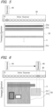
- FIG. 5 is a schematic diagram showing a first example of a test pattern image to be read for imaging calibration of the inline scanner 30 (simply referred to below as "imaging calibration"), along with the inline scanner 30 and the colorimeter 40.
- the inline scanner 30 generates test pattern imaging data by capturing a calibration patch, which is a predetermined primary-color portion of a predetermined test pattern image 51 formed as a printed image on the paper 5 by the recording portion 205, as shown in FIG. 5 .
- the calibration patch is subjected to color measurement by the colorimeter 40, resulting in colorimetric data.
- imaging calibration data for imaging calibration of the inline scanner 30 is generated (details will be described later).
- primary color refers to the subtractive primary color yellow (Y), magenta (M), or cyan (C).
- Such primary-color portions of the test pattern image 51 are formed with constant densities across the width of the paper 5 by the recording portion 205 and arranged in descending order of density (51a, 51b,..., 51n), as shown in FIG. 5 .
- primary-color patches instead of using primary-color patches as calibration patches, secondary- or tertiary-color patches may be used. However, in such a case, color system conversion is required for generating imaging calibration data and performing imaging calibration based on the imaging calibration data (details will be described later).
- FIG. 6 is a schematic diagram showing a second example of the test pattern image to be read for imaging calibration of the inline scanner 30, along with the inline scanner 30 and the colorimeter 40.
- a test pattern image for imaging calibration of the inline scanner 30 is selected from a printed image (target printed image) formed on the paper 5 by the recording portion 205 based on print data generated from manuscript data, e.g., from a target printed image 50 shown in FIG. 6 (the selected image will be referred to below as the "selected partial image” or simply as the "partial image”).
- the target printed image 50 includes a partial image 511 and a main image 512 (an image that is to be used as a printed material after the partial image 511 is cut out from the paper 5).
- the partial image 511 After being selected from the target printed image 50, the partial image 511 is captured by some imaging element (s) of the inline scanner 30 as a calibration patch, resulting in test pattern imaging data.
- the partial image 511 is subjected to color measurement by the colorimeter 40 after the colorimeter 40 is moved to a position where color measurement is possible, whereby colorimetric data is generated.
- imaging calibration data for imaging calibration of the inline scanner 30 is generated.
- the partial image 511 to be selected from the target printed image 50 the following two conditions need to be satisfied:
- FIG. 7 is a schematic diagram showing a third example of the test pattern image to be read for imaging calibration of the inline scanner 30, along with the inline scanner 30 and the colorimeter 40.
- the inline scanner 30 generates test pattern imaging data by capturing a test pattern image 51 for shading correction, as shown in FIG. 7 , formed as a printed image on the paper 5 by the recording portion 205. Based on the test pattern imaging data, correction data for shading correction is generated.
- the term "shading correction” refers to a correction applied to print data, etc., in accordance with characteristics of each printhead of the recording portion 205 in order to inhibit printed images from having uneven densities due to variations in the amounts of ink ejected from the printheads.
- test pattern image 51 includes images formed with constant densities across the width of the paper 5 by the recording portion 205 and arranged in descending order of density (51a', 51b',..., 51n'), as shown in FIG. 7 .
- the test pattern image 51 in FIG. 7 includes images formed with constant densities across the width of the paper 5 by the recording portion 205 and arranged in descending order of density (51a', 51b',..., 51n'), as shown in FIG. 7 .
- FIG. 8 is a schematic diagram showing a fourth example of the test pattern image to be read for imaging calibration of the inline scanner 30, along with the inline scanner 30 and the colorimeter 40.
- shading correction is performed up to the halftone color in real time during a printing operation using the test pattern image 51 in the third example ( FIG. 7 )
- paper waste occurs because such shading correction requires a halftone test pattern image to be formed as a printed image.
- the test pattern image 51 for shading correction only includes solid images (100% density images)
- the test pattern image 51 is placed outside the target printed image 50, i.e. outside the boundaries of a page, as shown in FIG. 8 , thereby allowing real-time shading correction.
- the target printed image 50 includes representative color patches 52 of the same colors as both halftone colors and specific colors, and the representative color patches 52 are placed in an unused area outside the target printed image 50, as shown in FIG. 8 .
- the representative color patches 52 are used as calibration patches for the inline scanner 30 and the colorimeter 40 to perform imaging and color measurement and thereby obtain test pattern imaging data and colorimetric data, based on which imaging calibration data for imaging calibration of the inline scanner 30 is generated.
- the CPU 111 of the control portion 100 executes the control program 17 after reading the control program 17 from the auxiliary storage device 12 into the memory 112 (see FIG. 2 ), whereby the recording portion 205, the transport mechanism, etc., of the printing mechanism 200 are controlled to perform printing on the paper 5, and the inline scanner 30 and the colorimeter 40 are also controlled to perform imaging and color measurement on a printed image formed on the paper 5 and thereby obtain imaging data for the printed image. Based on the imaging data, the quality of the printed image is determined.
- the CPU 111 executes the printing control process 18a and the inspection control process 18b in accordance with the control program 17, thereby realizing the printing apparatus's original function of forming a printed image on the paper 5 and an additional printed image inspection function for inspecting the printed image using the inline scanner 30, etc., in the printing mechanism 200.
- the printing apparatus 10 according to the present embodiment includes a printed image inspection device realized by the inline scanner 30 serving as the imaging portion, the colorimeter 40, the moving mechanism 45 for the colorimeter 40 (see FIG. 3 ), the recording portion 205, the transport mechanism, and the control portion 100 executing the inspection control process 18b.
- FIG. 9 is a flowchart showing a control process of the printing apparatus 10 in the present embodiment, including the printing control process 18a and the inspection control process 18b, which are realized by the CPU 111 executing the control program 17 (the control process of the printing apparatus 10 will be simply referred to below as the "control process").
- the control portion 100 controls the printing mechanism 200, the paper feeding portion 202, and the paper winding portion 208 (see FIGS. 1 and 2 ) in accordance with the procedure shown in FIG. 9 .
- the CPU 111 executes the control program 17 after reading the control program 17 from the auxiliary storage device 12 into the memory 112. This activates the control process shown in FIG.
- the inspection control process 18b is realized by steps S14 to S18, S220, and S22 to S28 of the control process in FIG. 9 .
- the image processing portion 117 is controlled to rasterize manuscript data provided externally via the network 3 and thereby generate print data in bitmap format (step S12).
- the print data contains data for a target image, which is an input image represented by the manuscript data.
- a process for imaging calibration of the inline scanner 30 is performed (step S14). Specifically, this process initially eliminates variations in imaging sensitivity among the imaging elements 31 of the inline scanner 30 for example, by setting sensitivity variation correction factors by which to multiply output values of the imaging elements in the inline scanner 30.
- FIG. 10 is a diagram for describing the calibration of the colorimeter 40.
- the printing mechanism 200 is equipped with a white reference plate 42 for use in calibrating the colorimeter 40.
- the white reference plate 42 is disposed so as to face the color detection surface of the colorimeter 40 when the colorimeter 40 is located at a predetermined position outside a range where the colorimeter 40 can be positioned for performing color measurement on a printed image on the paper 5, but within a range where the colorimeter 40 can move in the width direction (for example, the predetermined position is an end position of the movable range).
- the colorimeter 40 is calibrated by moving the colorimeter 40 to the predetermined position using the moving mechanism 45 and causing the colorimeter 40 to perform color measurement on the white reference plate 42.
- FIG. 11 is a flowchart showing the calibration data generation process in the present embodiment.
- the CPU 111 operates as described below.
- the recording portion 205 and the transport mechanism are controlled such that the recording portion 205 forms calibration patches on the paper 5 as printed images (step S182).
- the calibration patch can be printed as: a part or whole of a test pattern image formed separately from a target printed image, as in the first and third examples ( FIGS. 5 and 7 ); an image simultaneously formed with a target printed image outside the target printed image, as in the fourth example ( FIG. 8 ); or a calibration patch (including a test pattern) constituting a part (partial image) of a target printed image, as in the second example ( FIG. 6 ).
- the calibration patch formed as the printed image in step S182 is any of the printed images as appearing in the first and third examples ( FIGS. 5 and 7 ).
- Printed images of calibration patches as shown in the second and fourth examples ( FIGS. 6 and 8 ) can be formed by an image printing process (step S210) in the second embodiment to be described later (see FIGS. 22 and 23 ).
- the moving mechanism 45 moves the colorimeter 40 to a calibration patch reading position (step S184), i.e., the colorimeter 40 is moved to a position at which to perform color measurement on a printed image of a calibration patch, as shown in, for example, FIG. 6 .
- the printed image of the calibration patch is read by the inline scanner 30 and the colorimeter 40 (step S186).
- the inline scanner 30 captures the printed image of the calibration patch and thereby generates calibration patch imaging data.
- the calibration patch imaging data is imaging data for a part or whole of the printed image of the test pattern, and therefore will also be referred to below as the "test pattern imaging data”.
- the colorimeter 40 performs color measurement on the printed image of the calibration patch and thereby generates colorimetric data.
- the imaging elements 31 included in the inline scanner 30 are arranged in the paper width direction, and one of the imaging elements 31 that is located at a position corresponding to the position of the calibration patch in the paper width direction (this imaging element 31 being shaded with oblique lines in FIGS. 5 to 7 ) is used to capture the printed image of the calibration patch.
- imaging calibration data is generated based on these data (step S188).
- the imaging calibration data provides correction factors by which to multiply output values of the respectively corresponding imaging elements 31 included in the inline scanner 30, and each correction factor is determined such that the value obtained by multiplying the output value of the corresponding imaging element by the correction factor corresponds to a colorimetric value obtained by the colorimeter 40 measuring the calibration patch.
- correction factors are contained in a lookup table prepared in advance. Specifically, in a printed image inspection process to be described later ( FIG.
- a correction factor for imaging data of a target printed image is prepared for each imaging element 31 of the inline scanner 30 as calibration data for imaging calibration of the inline scanner 30.
- a lookup table (referred to below as a "correction factor LUT") 19 is prepared in advance for mapping the correction factors Ck of the imaging elements 31-k to integers k such that 1 ⁇ k ⁇ n (see FIG. 2 ).
- the correction factor LUT 19 is updated with the new correction factors C1 to Cn.
- the inline scanner 30 serving as the imaging portion includes n imaging elements 31-1 to 31-n and that the imaging calibration data provides correction factors C1 to Cn.
- step S20 an image printing process (step S210) and a printed image inspection process (step S220) are executed concurrently. Note that in the example shown in FIG. 9 , steps S210 and S220 are executed on a page by page basis, and when steps S210 and S220 are executed for a page, whether the page is the last page of the print data is determined in step S22 to be described later.
- imaging calibration time at which imaging calibration is performed on the inline scanner 30
- color measurement calibration time at which color measurement calibration is performed on the colorimeter 40
- FIG. 12 is a flowchart showing the image printing process in the present embodiment.
- the CPU 111 operates as described below.
- the print data generated in step S12 is corrected (step S212).
- the correction is intended to ensure that images represented by the print data are recorded well on the paper 5 (i.e., printed images are formed well on the paper 5), and here, shading correction is performed to prevent the printed images from having uneven densities due to variations in the amounts of ink ejected from the printheads.
- other corrections may also be included.
- the printing mechanism 200 and other components are controlled to form the images represented by the print data, i.e., target images, on the paper 5 as target printed images (step S214) .
- the paper feeding portion 202, the drive rollers 203 and 207, the drying portion 206, the inline scanner 30, the colorimeter 40, and the paper winding portion 208 are controlled along with the recording portion 205.
- the recording portion 205 sequentially records the target images onto the paper 5 being transported while being unwound from the paper feeding portion 202. That is, the target printed images are sequentially formed on the paper 5.
- the paper 5 with the target printed images sequentially formed as above is dried by the drying portion 206, and then the target printed images are subjected to imaging by the inline scanner 30 before the paper 5 is wound up onto the paper winding portion 208.
- the imaging by the inline scanner 30 and a process based on imaging data resulting from the imaging are described below in conjunction with the printed image inspection process.
- FIG. 13 is a flowchart showing the printed image inspection process in the present embodiment.
- the CPU 111 operates as described below.
- step S222 the target printed images formed on the paper 5 are sequentially captured by the inline scanner 30 (step S222).
- step S220 is executed on a page by page basis, as described earlier, and therefore when imaging data is generated by capturing target printed images for one page, control advances next to step S224.
- step S224 the imaging data for one page generated in step S222 is corrected using the correction factor LUT 19 updated in step S18.
- the correction corresponds to imaging calibration of the inline scanner 30.
- the imaging data thus corrected (referred to below as the "corrected imaging data") is compared with, for example, the print data as originally provided, whereby the quality of the target printed images captured in step S222 is determined (step S226).
- the determination results are, for example, stored to and/or displayed in the control portion 100, but the details of such operations are not directly relevant to the present invention and therefore will not be elaborated upon.
- step S220 ends, and control proceeds to step S22.
- step S22 it is determined whether all pages of the print data have been printed and inspected through the formation and inspection of the target printed images in steps S210 and S220. If the determination result indicates that the print data has a page that has not yet been printed and inspected, control proceeds to step S24 to determine whether the time for imaging calibration of the inline scanner 30 (imaging calibration time) has arrived.
- step S24 determines whether the imaging calibration time has not yet arrived. If the determination result indicates that the imaging calibration time has not yet arrived, control returns to step S20, and steps from S20 onward are executed as described above.
- step S24 if it is determined in step S24 that the imaging calibration time has not yet arrived and also if it is determined in step S28 that the color measurement calibration time has not yet arrived, the following steps are repeatedly executed in the order: S20 (S210 and S220) -> S22 ⁇ S24 -> S28, until all pages of the print data are printed and inspected.
- steps S20 to S28 if it is determined in step S24 that the imaging calibration time has arrived, control returns to step S18 to perform the calibration data generation process and thereby update the correction factor LUT 19 (see FIG. 11 ), and thereafter steps from S20 onward are executed.
- step S28 if it is determined in step S28 that the color measurement calibration time has arrived, control returns to step S16 to calibrate the colorimeter 40, and steps from S20 onward are executed after the correction factor LUT 19 is updated by the calibration data generation process ( FIG. 11 ).
- step S22 if it is determined in step S22 that all pages of the print data have been printed and inspected, the control process of the printing apparatus 10 (i.e., the print operation) ends for the print data generated from a single set of manuscript data.
- the correction factor LUT 19 for imaging calibration is prepared in advance, and when the imaging calibration time arrives during the printing operation, the correction factor LUT 19 is updated (see step S24 -> step S18 in FIG. 9 ) with the imaging calibration data generated in the calibration data generation process (step S18). Further, in the printed image inspection process (step S220), the imaging data of the printed images is corrected using the correction factor LUT 19, thereby achieving imaging calibration (step S224 in FIG. 13 ).
- the update of the correction factor LUT 19 and the correction of the imaging data with the correction factor LUT 19 will be described below with a focus on the generation of related data.
- FIG. 14 is a flow diagram showing a first example of the procedure for updating the correction factor LUT in the present embodiment.
- rectangles represent hardware or software that performs predetermined processes (processing routines included in the control program 17), and octagons represent data (including a lookup table). Such a schematic representation is also used in FIGS. 16 through 21 to be described later.
- the inline scanner 30 captures a printed image of a test pattern including a calibration patch formed on the paper 5 and thereby generates test pattern (TP) imaging luminance data Lsc as calibration imaging data (steps S182 to S186 in FIG. 11 ), as shown in FIG. 14 .
- test pattern will also be abbreviated below as "TP”.
- the printed image of the calibration patch is subjected to color measurement by the colorimeter 40, thereby generating TP colorimetric data Dcm as calibration colorimetric data (step S186 in FIG. 11 ).
- the TP imaging luminance data Lsc and the TP colorimetric data Dcm are RGB luminance data and CMY density data, respectively, and therefore in order to generate imaging calibration data from the data Lsc and Dcm, it is necessary to match the data Lsc and Dcm in terms of color system. Accordingly, in this example, the TP imaging luminance data Lsc is converted to density data by performing a color system conversion process P10. The color system conversion process P10 is performed using a lookup table (LUTsc) prepared in advance. This results in TP imaging density data Dsc.
- LUTsc lookup table
- a process P30 is performed to update a correction factor LUT 151 for imaging calibration (step S188 in FIG. 11 ).
- reference numeral "151" is used in place of reference numeral "19".
- the difference between the TP imaging density data Dsc and the TP colorimetric data Dcm obtained as above is determined, and the correction factors C1 to Cn mentioned earlier are determined so as to eliminate or at least reduce the difference. For example, when the test pattern image is a printed image including calibration patches recorded with constant densities in the paper width direction (see FIG.
- the correction factors C1 through Cn thus obtained anew are used to update the correction factor LUT 151.
- FIG. 15 is a graph for describing a second example of the procedure for updating the correction factor LUT 19. Note that to distinguish the correction factor LUT 19 to be updated in the present example from correction factors LUT to be updated in other examples, reference numeral "152" is used in place of reference numeral "19".
- color measurement values corresponding to luminance values obtained by the inline scanner 30 are obtained in advance for each of the RGB channels by the inline scanner 30 and the colorimeter 40 performing imaging and color measurement on primary-color patches with various densities.
- a correction factor LUT 152 is created according to the degree of deviation of the correspondence between calibration imaging data values and colorimetric data values from the relationship between the luminance values and the density values as shown in FIG. 15 .
- the calibration imaging data values are luminance values obtained by the inline scanner 30 capturing images of calibration patches
- the colorimetric data values are density values obtained by the colorimeter 40 performing color measurement on the images of the calibration patches.
- the correction factor LUT 152 is updated during the printing operation by the inline scanner 30 and the colorimeter 40 performing imaging and color measurement on the calibration patches.
- FIG. 16 is a flow diagram showing a first example of the procedure for correcting the imaging data for imaging calibration in the present embodiment.
- the printing mechanism 200 forms a target printed image on the paper 5 based on print data
- the target printed image is captured by the inline scanner 30, thereby generating target imaging luminance data LOsc as target imaging data (step S222 in FIG. 13 ).
- the target imaging luminance data LOsc is converted to target imaging density data DOsc by the color system conversion process P10.
- the target imaging density data DOsc is subjected to an imaging calibration process P40.
- the target imaging density data DOsc is corrected using the correction factor LUT 151, which is updated as shown in FIG. 14 , resulting in corrected imaging data DOcsc (step S224 in FIG. 13 ).
- the correction here corresponds to imaging calibration.
- FIG. 17 is a flow diagram showing a third example of the procedure for updating the correction factor LUT 19.
- the correction factor LUT is integrated with the lookup table (LUTsc) for the color system conversion process P10 in the first example shown in FIG. 14 , resulting in a single lookup table (referred to below as a "conversion/correction factor LUT") 153.
- LUTsc lookup table
- conversion/correction factor LUT a process P32 for updating the conversion/correction factor LUT 153 is performed based on TP imaging luminance data Lsc generated by the inline scanner 30 and TP colorimetric data Dcm obtained by the colorimeter 40, as shown in FIG. 17 .
- the conversion/correction factor LUT 153 is (created and) updated as a lookup table for making some correction for imaging calibration without converting RGB luminance data, which is generated as imaging data by the inline scanner 30, to density data.
- FIG. 18 is a flow diagram showing a second example of the procedure for correcting the imaging data for imaging calibration in the present embodiment.
- the conversion/correction factor LUT 153 is used to generate corrected imaging data DOcsc.
- the target imaging luminance data LOsc is subjected to an image calibration process P42 using the conversion/correction factor LUT 153, so that the target imaging luminance data LOsc is converted to density data and corrected for image calibration at the same time.
- corrected imaging data DOcsc is generated (see step S224 in FIG. 13 ).
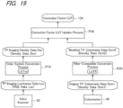
- FIG. 19 is a flow diagram showing a fourth example of the procedure for updating the correction factor LUT 19.
- the colorimeter 40 contains a lookup table (LUTfl) that takes account of the characteristics of the color filters used in the inline scanner 30. Specifically, in this example, as shown in FIG. 19 , the colorimeter 40 generates original TP colorimetric data Dcm1 as colorimetric data for calibration, and the original TP colorimetric data Dcm1 is converted to modified TP colorimetric data Dcm2 by a filter-compatible conversion process P20.
- LUTfl lookup table
- the filter-compatible conversion process P20 is a process for modifying colorimetric data while taking account of the characteristics of the color filters in the inline scanner 30, and thereby allowing appropriate imaging calibration over a wider color reproduction range.
- the filter-compatible conversion process P20 uses a lookup table (LUTfl) adapted therefor.
- LUTfl lookup table
- the TP imaging luminance data Lsc generated by the inline scanner 30 is converted to TP imaging density data Dsc by the color system conversion process P10, as in the first example of the procedure for updating the correction factor LUT ( FIG. 14 ).
- the correction factor LUT 154 is updated with correction factors C1 to Cn obtained in the same manner as in the first example, by a process P34 for updating the correction factor LUT.
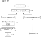
- FIG. 20 is a flow diagram showing a fifth example of the procedure for updating the correction factor LUT 19.
- reference numeral "155" is used in place of reference numeral "19".
- the correction factors contained in the correction factor LUTs 151 through 154 described above are those for imaging data expressed in densities, but the correction factors may be those for imaging data in other color systems.
- the correction factor LUT 155 used in this example contains correction factors for imaging data in the CIE 1976 L*a*b* color system. By using such a correction factor LUT 155, imaging calibration can be performed even when secondary- or tertiary-color patches are used as calibration patches.
- the procedure for updating the correction factor LUT 155 in the present example will be described below.
- the inline scanner 30 captures a printed image of a calibration patch or a test pattern including the calibration patch and thereby generates TP imaging luminance data Lsc, and the TP imaging luminance data Lsc is converted to TP imaging L*a*b* data Dsc2, which is imaging data in the CIE 1976 L*a*b* color system, by a color system conversion process P12 using a lookup table LUTsc2 (steps S182 to S186 in FIG. 11 ).
- the printed image of the calibration patch is also subjected to color measurement by the colorimeter 40, so that TP colorimetric L*a*b* data Dcm3, which is colorimetric data in the CIE 1976 L*a*b* color system, is generated as colorimetric data for calibration (step S186 in FIG. 11 ). Thereafter, a process P36 is performed to update the correction factor LUT 155 for imaging calibration (step S188 in FIG. 11 ).
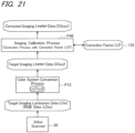
- FIG. 21 is a flow diagram showing a third example of the procedure for correcting the imaging data for imaging calibration in the present embodiment.
- the printing mechanism 200 forms a target printed image on the paper 5 based on print data
- the target printed image is captured by the inline scanner 30, thereby generating target imaging luminance data LOsc as target imaging data (step S222 in FIG. 13 ).
- the target imaging luminance data LOsc is converted to target imaging L*a*b* data DOsc2 by the color system conversion process P12 using the lookup table LUTsc2.
- the target imaging L*a*b* data DOsc2 is subjected to an imaging calibration process P46.
- the imaging calibration process P46 the target imaging L*a*b* data DOsc2 is corrected with the correction factor LUT 155, which is updated as shown in FIG. 20 , resulting in corrected imaging L*a*b* data DOcsc1 (step S224 in FIG. 13 ).
- the correction here corresponds to imaging calibration.
- the quality of the target printed image is determined based on the corrected imaging L*a*b* data DOcsc1 (step S226 in FIG. 13 ).
- the inline scanner 30 serving as the imaging portion is subjected to imaging calibration using a blank area of the paper before a printing operation, and the inline scanner 30 is also subjected to imaging calibration during the printing operation (step S24 -> step S18 in FIG. 9 ).
- the inline scanner 30 is also subjected to imaging calibration during the printing operation (step S24 -> step S18 in FIG. 9 ).
- the calibration patch is subjected to imaging and color measurement by the inline scanner 30 and the colorimeter 40 (see FIGS. 5 , 7 , and 9 ).
- the imaging data obtained by the inline scanner 30 capturing the target printed image formed on the paper 5 is subjected to a correction using the correction factor LUT, thereby achieving imaging calibration (see step S224 in FIG. 13 , and FIGS. 16 , 18 , and 21 ). Based on the imaging data subjected to the correction (i.e., the corrected imaging data), the quality of the target printed image is determined (see step S226 in FIG. 13 ).
- imaging calibration is performed even during the printing operation by using the colorimetric data for the calibration patch, and therefore, even if the imaging sensitivity of the inline scanner 30 varies due to environmental changes, such as temperature changes, during the printing operation, imaging calibration can be accurately performed in real time in response to such variations. Accordingly, when the density of the printed image formed on the paper 5 varies during the printing operation, such density variations can be properly detected by the printed image inspection process based on the imaging data obtained by the inline scanner 30 (see step S220 in FIG. 9 , and FIG. 13 ). In other words, it is possible to properly monitor the density of the printed image during the printing operation while eliminating the influence of changes in the characteristics of the printed image inspection device due to environmental changes, such as temperature changes. Note that in the present embodiment, highly accurate imaging calibration data can be obtained by performing imaging and color measurement on calibration patches that include halftone colors and secondary colors, and therefore, correcting an inspection target image using a correction factor LUT based on the obtained imaging calibration data allows accurate imaging calibration.
- the inline scanner 30 and the colorimeter 40 which obtain the calibration imaging data and the calibration colorimetric data required for imaging calibration as described above, are positioned so as to face the imaging support roller 204a and the color measurement support roller 204b, respectively, as shown in FIG. 4 .
- test pattern images that are used for imaging calibration of the inline scanner 30 serving as the imaging portion are those shown in FIGS. 6 and 8 , i.e., the test pattern images are included in or arranged outside target printed images that are formed on the paper 5 based on print data.
- components of the printing apparatus 10 according to the present embodiment that are the same as or correspond to those in the first embodiment are denoted by the same reference numerals and will not be elaborated upon.
- FIG. 22 is a flowchart showing a control process of the printing apparatus 10 in the present embodiment, including the printing control process 18a and the inspection control process 18b, which are realized by the CPU 111 executing the control program 17 (the control process of the printing apparatus 10 will be simply referred to below as the "control process").
- the control portion 100 controls the printing mechanism 200, the paper feeding portion 202, and the paper winding portion 208 (see FIGS. 1 and 2 ) in accordance with the procedure shown in FIG. 22 .
- the CPU 111 executes the control program 17 after reading the control program 17 from the auxiliary storage device 12 into the memory 112. This activates the control process shown in FIG. 22 and thereby causes the CPU 111 to operate as shown in FIG. 22 in accordance with the control program 17.
- the calibration data generation process (S18) is performed before the execution of the image printing process (S210), whereas in the second embodiment, the calibration data generation process (S26) is performed after the execution of the image printing process (S210).
- the test pattern images that are used in the present embodiment are those as shown in FIGS. 6 and 8 , and the test pattern images, along with calibration patches, are formed simultaneously with target printed images on the paper 5 based on the print data, as parts of the target printed images or as printed images outside the target printed images.
- FIG. 23 is a flowchart showing the calibration data generation process (S26) in the present embodiment.
- the CPU 111 operates as described below.
- the test pattern image, along with the calibration patches is formed on the paper 5 simultaneously with the target printed image as described above (see FIGS. 6 and 8 ), and therefore in the calibration data generation process (S26), an image of a calibration patch is initially selected from printed images including the target printed image, formed on the paper 5 (step S183) .
- the test pattern image, along with the calibration patches is specified in advance, and therefore control advances next to step S184 without any substantial processing being performed in step S183.
- the processing from step S184 onward in the calibration data generation process (S26) is the same as in the calibration data generation process (S18 in FIG. 11 ) in the first embodiment and therefore will not be elaborated upon.
- step S24 in FIG. 22 if it is determined in step S24 in FIG. 22 that the imaging calibration time has arrived before all pages of the print data are printed and inspected, the calibration data generation process (S26) is executed so that the correction factor LUT is updated. If it is determined in step S24 that the imaging calibration time has not yet arrived, control advances to step S28. The processing from step S28 onward is the same as in the control process ( FIG. 9 ) in the first embodiment.
- imaging calibration is performed on the inline scanner 30 by performing imaging and color measurement on the calibration patch at predetermined times during the printing operation (see steps S24 and S26 in FIG. 22 and step S224 in FIG. 13 ) .
- This renders it possible to achieve effects similar to those achieved by the first embodiment and properly monitor the density of the printed image during the printing operation while eliminating the influence of changes in the characteristics of the printed image inspection device due to environmental changes, such as temperature changes.
- the test pattern image for imaging calibration is formed as a part of the target printed image or outside the target printed image ( FIGS. 6 and 8 ), so that less paper is wasted for imaging calibration.
- the test pattern images that are used for imaging calibration of the inline scanner 30 serving as the imaging portion are those shown in FIGS. 7 and 8 , i.e., the test pattern images include those for shading correction on the amount of ink ejected by the recording portion 205 (such test pattern images will be referred to below as "shading correction TP images").
- shading correction TP images such test pattern images will be referred to below as "shading correction TP images"
- the calibration data generation process in the present embodiment differs from those in the first and second embodiments in relation to shading correction. All components of the printing apparatus 10 according to the present embodiment, excluding the calibration data generation process, are the same as or correspond to those in the first and second embodiments, and therefore the same or corresponding components will be denoted by the same reference numerals and will not be elaborated upon.
- the calibration data generation process in the present embodiment will be described below on the premise that the test pattern image shown in FIG. 7 is used.
- the test pattern image includes a plurality of image strips formed to extend in the paper width direction in the same color and density and to be arranged in the transport direction in different colors with different densities.
- FIG. 24 is a flowchart showing the calibration data generation process (S18) in the present embodiment.
- the CPU 111 operates as described below.
- a test pattern image (shading correction TP image) as shown in FIG. 7 is printed (step S192).
- a part of the test pattern image is used as a calibration patch, which is subjected to imaging and color measurement by the inline scanner 30 and the colorimeter 40, resulting in calibration imaging data and calibration colorimetric data to be used for updating the correction factor LUT (steps S194 to S198).
- the inline scanner 30 captures the test pattern image (shading correction TP image) in FIG. 7 and thereby generates test pattern image data, and a part of the test pattern image data that corresponds to the calibration patch is used as the calibration image data.
- the test pattern imaging data is corrected using the updated correction factor LUT, resulting in shading correction data (step S199).
- the shading correction data is used to correct the print data in the image printing process (step S220 in FIG. 9 , and FIG. 12 ).
- the shading correction data is used to correct the print data in the image printing process (step S220 in FIG. 9 , and FIG. 12 ).
- imaging calibration is performed on the inline scanner 30 by performing imaging and color measurement on the calibration patch at predetermined times during the printing operation (see step S18 in FIG. 9 and step S224 in FIG. 13 ).
- the inline scanner 30 captures an image of the calibration patch
- the inline scanner 30 captures the shading correction TP image including the calibration patch and thereby generates the test pattern imaging data, which is corrected with the correction factor LUT, resulting in the shading correction data.
- capturing the test pattern image for shading correction (shading correction TP image) doubles as capturing the test pattern image for imaging calibration (and the calibration patches included therein). This renders it possible to efficiently carry out shading correction and imaging calibration during the printing operation.
- the present invention is not limited to the above embodiments, and various other modifications can be made without departing from the scope of the invention.
- the present invention is applied to inkjet printing apparatuses, but the present invention can also be applied to printing apparatuses other than inkjet printing apparatuses by suitably modifying the configurations of the embodiments as necessary.
- a test pattern image including calibration patches may be placed outside the printed area, e.g., in a top end portion to be ultimately cut out from the paper 5, as shown in FIG. 25 .
- the test pattern image contains patches in colors desired to be accurately monitored and is placed outside the printed area above the target printed image 50.
- the test pattern image has a size that allows the inline scanner 30 and the colorimeter 40 to perform imaging and color measurement, respectively.
- imaging calibration is performed on the inline scanner 30 during the printing operation based on the colorimetric data obtained by the colorimeter 40, and therefore the inline scanner 30 can generate imaging data with correct density values.
- the printed image formed on the paper 5 includes a printhead density adjustment strip patch 54 placed outside the target printed image 50, as shown in FIG. 26 . This renders it possible to correct the print data provided to the printheads with reference to data obtained by reading the patch 54 and thereby stably maintain the specific color (color of interest) in the target printed image 50.
- FIG. 27 is a block diagram for describing an operation for correcting density variations by controlling the printheads using the density adjustment strip patch 54.
- One embodiment adapted for such an application as shown in FIG. 27 includes a subblock SB1 for calculating correction factors based on a calibration patch 52 read by the inline scanner 30 and the colorimeter 40, a subblock SB2 for reading the density adjustment strip patch 54 to obtain read signals and performing the above-described imaging calibration on the read signals, a correction data calculation portion P55 for generating color correction factors for print data based on image data resulting from the imaging calibration and reference data for a color of interest, and second multipliers 60 for correcting CMYK print data through multiplication by the color correction factors and providing the corrected print data to cyan (C), magenta (M), yellow (Y), and black (K) printheads 21.
- C cyan
- M magenta
- Y yellow
- K black
- the subblock SB2 includes an inline scanner 30 configured to read the density adjustment stripe patch 54 and thereby output imaging luminance data Lsc for the density adjustment stripe patch 54, a color conversion portion P51 configured to convert the imaging luminance data Lsc to CMYK density data Dsc, and a first multiplier P52 configured to correct the density data Dsc through multiplication by the correction factors obtained by the subblock SB1.
- the subblock SB2 performs imaging calibration for the imaging luminance data Lsc for the density adjustment stripe patch 54 outputted by the inline scanner 30. Therefore, even if the imaging sensitivity of the inline scanner 30 varies during the printing operation, the subblock SB2 can respond to such variations and output the density data Dsc for the density adjustment strip patch 54.
- the correction data calculation portion P55 calculates a color correction factor for each of the CMYK colors based on the density data Dcsc resulting from imaging calibration as above and the reference data for the color of interest, such that color differences are minimized between images printed in the color of interest by the printheads 21 and the reference data for the color of interest.
- CMYK color correction factors are used by the second multipliers 60 for multiplying the respective CMYK print data thereby.
- the multiplication results are provided to their corresponding printheads 21 for the respective colors.
- the operation of correcting density variations by controlling the printheads as above allows the density of the color of interest to be stably maintained in printed images.
- printhead control may be performed for each printhead array, each printhead, or each nozzle. Further, the amount of ink ejected from each printhead may be controlled by the drive waveform, drive timing, or drive voltage of the printhead. Moreover, instead of controlling the printheads, the CMYK correction density values may be provided to other elements capable of printed image density adjustments. For example, density variations may be corrected by reflecting the CMYK correction density values in print data processing for shading correction or in a screening process for print data generation.
- the correction factors are values by which to multiply the output values of the imaging elements 31.
- the correction factors may be values by which to multiply, for example, values obtained by subjecting the output values of the imaging elements to a color conversion process.
- the color system conversion process is performed on the TP imaging luminance data Lsc resulting from imaging by the inline scanner 30.
- the color system conversion process may be performed on the TP colorimetric data Dcm resulting from color measurement by the colorimeter 40.
Landscapes
- Engineering & Computer Science (AREA)
- Physics & Mathematics (AREA)
- Theoretical Computer Science (AREA)
- General Physics & Mathematics (AREA)
- General Engineering & Computer Science (AREA)
- Computer Vision & Pattern Recognition (AREA)
- Signal Processing (AREA)
- Multimedia (AREA)
- Quality & Reliability (AREA)
- Mathematical Physics (AREA)
- Accessory Devices And Overall Control Thereof (AREA)
- Ink Jet (AREA)
- Image Analysis (AREA)
- Spectrometry And Color Measurement (AREA)
- Image Input (AREA)
- Image Processing (AREA)
- Facsimiles In General (AREA)
- Facsimile Scanning Arrangements (AREA)
- Facsimile Image Signal Circuits (AREA)
Claims (14)
- Druckvorrichtung (10) mit einer Druckbildinspektionsfunktion, umfassend:einen Druckmechanismus (200);einen Abbildungsabschnitt (30);ein Kolorimeter (40); undeinen Steuerabschnitt (100), wobeider Druckmechanismus (200) umfasst:einen Transportmechanismus (203, 204, 204a, 204b, 207), der eingerichtet ist, ein Basismaterial (5) zu transportieren; undDruckköpfe (205k, 205c, 205m, 205y), die eingerichtet sind, auf eine Druckseite des Basismaterials (5) zu drucken,wobei der Steuerabschnitt (100) die Druckköpfe (203, 204, 204a, 204b, 207) und den Transportmechanismus (203, 204, 204a, 204b, 207) derart steuert, um ein gedrucktes Bild auf dem Basismaterial (5) zu bilden,der Steuerabschnitt (100) den Abbildungsabschnitt (30) und das Kolorimeter (40) derart steuert, dass, wenn ein Testmusterbild (51, 52, 511) zur Kalibrierung des Abbildens durch den Abbildungsabschnitt (30) als ein Teil oder als Ganzes des gedruckten Bildes gebildet wird, der Abbildungsabschnitt (30) das Testmusterbild erfasst und dabei Testmuster-Abbildungsdaten (Lsc) erzeugt und das Kolorimeter (40) eine Farbmessung an dem Testmusterbild durchführt und dabei kolorimetrische Daten (Dcm, Dcm1, Dcm3) erzeugt,der Steuerabschnitt (100) Abbildungskalibrierungsdaten (151 bis 155) basierend auf den Testmuster-Abbildungsdaten und der kolorimetrischen Daten erzeugt,der Steuerabschnitt (100) den Abbildungsabschnitt (30) derart steuert, dass, nachdem die Abbildungskalibrierungsdaten (151 bis 155) erzeugt sind, Ziel-Abbildungsdaten (LOsc) durch den Abbildungsabschnitt (30) erzeugt werden, der ein gedrucktes Zielbild (50) erfasst, das basierend auf Druckdaten gebildet wird, die ein zu druckendes Eingangsbild darstellen,der Steuerabschnitt (100) die Ziel-Abbildungsdaten (LOsc) basierend auf den Abbildungskalibrierungsdaten (151 bis 155) korrigiert,der Steuerabschnitt (100) die Qualität des gedruckten Zielbildes (50) basierend auf korrigierten Ziel-Abbildungsdaten (DOcsc, DOcsc1) bestimmt, undwährend des Druckvorgangs von einem Beginn bis zu einem Ende des Druckens auf das Basismaterial (5) durch den Druckmechanismus (200),der Steuerabschnitt (100) den Abbildungsabschnitt (30) und das Kolorimeter (40) derart steuert, dass der Abbildungsabschnitt (30) die Testmuster-Abbildungsdaten (Lsc) in vorbestimmten Zeitintervallen neu erzeugt und das Kolorimeter (40) die kolorimetrischen Daten (Dcm, Dcm1, Dcm3) in vorbestimmten Zeitintervallen neu erzeugt, undder Steuerabschnitt (100) die Abbildungskalibrierungsdaten (151 bis 155) in vorbestimmten Zeitintervallen basierend auf den Testmuster-Abbildungsdaten, die neu erzeugt wurden, und den kolorimetrischen Daten, die neu erzeugt wurden, neu erzeugt und dadurch die Abbildungskalibrierungsdaten aktualisiert, die zur Korrektur der Ziel-Abbildungsdaten (LOsc) zu verwenden sind.
- Druckvorrichtung (10) gemäß Anspruch 1, wobei der Druckmechanismus (200), während des Druckvorgangs, das gedruckte Zielbild (50) auf dem Basismaterial (5) basierend auf Manuskriptdaten bildet.
- Druckvorrichtung (10) gemäß Anspruch 1, wobei der Steuerabschnitt (100) eine Farbsystemumwandlung entweder an den Testmuster-Abbildungsdaten (Lsc) oder den kolorimetrischen Daten (Dcm, Dcm1, Dcm3) oder an beiden derart durchführt, dass die Testmuster-Abbildungsdaten und die kolorimetrischen Daten in Bezug auf das Farbsystem angepasst sind;der Steuerabschnitt (100) eine Differenz zwischen den Testmuster-Abbildungsdaten (Dsc, Dsc2) und den kolorimetrischen Daten (Dcm, Dcm2, Dcm3) nach der Farbsystemumwandlung berechnet; undder Steuerabschnitt (100) die Abbildungskalibrierungsdaten (151 bis 155) erzeugt, die zur Korrektur der Ziel-Abbildungsdaten (LOsc) verwendet werden, um die Differenz zu verringern.
- Druckvorrichtung (10) gemäß Anspruch 1 oder 2, wobei der Steuerabschnitt (100) die Druckköpfe (203, 204, 204a, 204b, 207) und den Transportmechanismus (203, 204, 204a, 204b, 207) derart steuert, dass das Testmusterbild (51, 52) an einer Position erzeugt wird, die sich von einer Position unterscheidet, an der das gedruckte Zielbild (50) erzeugt wird.
- Druckvorrichtung (10) gemäß Anspruch 1 oder 2, wobei,der Abbildungsabschnitt (30) die Testmuster-Abbildungsdaten (Lsc) durch Erfassen eines Teilbildes (511) erzeugt, das als das Testmusterbild aus dem gedruckten Zielbild (50) ausgewählt wird,das Kolorimeter (40) die kolorimetrischen Daten (Dcm) erzeugt, indem es eine Farbmessung an dem Teilbild (511) durchführt, unddas Teilbild (511) eine Größe aufweist, die es dem Abbildungsabschnitt (30) und dem Kolorimeter (40) ermöglicht, das Abbilden bzw. eine Farbmessung durchzuführen.
- Druckvorrichtung (10) gemäß einem der Ansprüche 1 bis 5, ferner umfassend einem Bewegungsmechanismus (45), der eingerichtet ist, das Kolorimeter (40) zu bewegen, wobeider Abbildungsabschnitt (30) eine Vielzahl von Abbildungselementen (31) umfasst, die in einer Breitenrichtung senkrecht zu einer Transportrichtung des Basismaterials angeordnet sind, undder Steuerabschnitt (100) den Bewegungsmechanismus (45) veranlasst, das Kolorimeter (40) in der Breitenrichtung derart zu bewegen, dass das Kolorimeter kolorimetrische Daten (Dcm) erzeugt, die den von den Abbildungselementen (31) erzeugten Testmuster-Abbildungsdaten (Lsc) entsprechen.
- Druckvorrichtung (10) gemäß einem der Ansprüche 1 bis 5, wobeider Transportmechanismus eine erste und eine zweite Transportwalze (204a, 204b) umfasst, die teilweise von dem Basismaterial (5) derart umhüllt sind, dass die erste und die zweite Transportwalze eine Transportrichtung des Basismaterials mit dem gedruckten Bild ändern,der Abbildungsabschnitt (30) mit einer Abbildungsfläche derart angeordnet ist, dass dieser der Druckseite des Basismaterial (5) in einem Abschnitt zugewandt ist, an dem das Basismaterial mit der ersten Transportwalze (204a) in Kontakt steht, unddas Kolorimeter (40) mit einer Farberfassungsfläche derart angeordnet ist, dass dieses der Druckseite des Basismaterial (5) an einem Abschnitt zugewandt ist, an dem das Basismaterial mit der zweiten Transportwalze (204b) in Kontakt steht.
- Druckvorrichtung gemäß Anspruch 7, wobeider Transportmechanismus derart eingerichtet ist, dass die erste Transportwalze (204a) das Basismaterial (5) an einem Abschnitt kontaktiert, an dem das Basismaterial horizontal transportiert wird, undder Abbildungsabschnitt (30) vertikal über der ersten Transportwalze (204a) angeordnet ist.
- Druckvorrichtung gemäß Anspruch 7, wobei das Kolorimeter (40) derart angeordnet ist, dass die Farberfassungsfläche einem Abschnitt der Druckseite zugewandt ist, der einer Umfangsmitte der zweiten Transportwalze (204b) an dem Abschnitt entspricht, an dem das Basismaterial (5) mit der zweiten Transportwalze in Kontakt steht.
- Druckvorrichtung gemäß Anspruch 9, wobeider Transportmechanismus derart eingerichtet ist, dass die zweite Transportwalze (204b) die Transportrichtung des Basismaterials (5) von einer horizontalen Richtung in eine vertikale Richtung oder umgekehrt umschaltet, unddas Kolorimeter (40) derart angeordnet ist, dass es auf einer schrägen Linie liegt, die sich von einem Punkt auf einer Mittelachse der zweiten Transportwalze (204b) in einer Ebene senkrecht zu der Mittelachse der zweiten Transportwalze erstreckt, wobei die schräge Linie relativ zur vertikalen Richtung geneigt ist.
- Druckgerät gemäß Anspruch 10, wobei das Kolorimeter (40) derart angeordnet ist, dass die schräge Linie einen Winkel von 30 bis 60 Grad mit der vertikalen Richtung bildet.
- Druckvorrichtung gemäß Anspruch 7, wobeidie Druckköpfe (205k, 205c, 205m, 205y) jeweils eine Vielzahl von Düsen aufweisen, die in einer Breitenrichtung senkrecht zu der Transportrichtung des Basismaterials (5) angeordnet sind und Tinte aus den Düsen auf das Basismaterial (5) ausstoßen,der Steuerabschnitt (100) die Druckköpfe und den Transportmechanismus derart steuert, um ein Bild für die Schattierungskorrektur auf dem Basismaterial (5) als das Testmusterbild (51) zu bilden, wobei das Bild für die Schattierungskorrektur verwendet wird, um Schwankungen in der Menge des Tintenausstoßes zwischen den Düsen zu kompensieren,der Steuerabschnitt (100) die Testmuster-Abbildungsdaten, die von dem Abbildungsabschnitt (30), der das Testmusterbild (51) erfasst, erhalten wurden, basierend auf den Abbildungskalibrierungsdaten (151 bis 155) korrigiert, und Schattierungskorrekturdaten basierend auf den korrigierten Testmuster-Abbildungsdaten erzeugt,der Steuerabschnitt (100) die Druckdaten basierend auf den Schattierungskorrekturdaten korrigiert, undder Steuerabschnitt (100) die Druckköpfe und den Transportmechanismus derart steuert, um das gedruckte Zielbild (50) auf dem Basismaterial (5) basierend auf korrigierten Druckdaten zu bilden.
- Druckverfahren für eine Druckvorrichtung (10) mit einer Druckbildinspektionsfunktion, umfassend:einen Druckschritt (S182, S214) des Bildens eines gedruckten Bildes auf einem Basismaterial (5) durch Drucken auf einer Druckseite des Basismaterials (5), während das Basismaterial (5) transportiert wird;einen Abbildungsschritt (S186, S222) des Erfassens des gedruckten Bildes;einen Farbmessungsschritt (S186) des Durchführens einer Farbmessung an einem ganzen oder einem Teil des gedruckten Bildes;einen Kalibrierungsschritt (S188, S198, S199, S224) des Kalibrierens des Abbildens in dem Abbildungsschritt (S186, S222); undeinen Bestimmungsschritt (S226) des Bestimmens der Qualität des gedruckten Bildes, wobeiwährend des Druckvorgangs von einem Anfang bis zu einem Ende des Drucks auf dem Basismaterial (5) durch den Druckschritt (S182, S214),in dem Druckschritt (S182, S214) ein Testmusterbild (51, 52, 511) für die Kalibrierung im Kalibrierungsschritt (S188, S198, S199, S224) als Teil oder als Ganzes des gedruckten Bildes gebildet wird,in dem Abbildungsschritt (S186, S222) Ziel-Abbildungsdaten (LOsc) durch Erfassen eines auf dem Basismaterial (5) gebildeten gedruckten Zielbildes (50) erzeugt werden und Testmuster-Abbildungsdaten (Lsc) in vorbestimmten Zeitintervallen durch Erfassen des Testmusterbildes (51, 52, 511) neu erzeugt werden,in dem Farbmessungsschritt (S186) kolorimetrische Daten (Dcm, Dcm1, Dcm3) in vorbestimmten Zeitintervallen neu erzeugt werden, indem eine Farbmessung an dem Testmusterbild (51, 52, 511) durchgeführt wird,in dem Kalibrierungsschritt (S188, S224) Abbildungskalibrierungsdaten (151 bis 155) in vorbestimmten Zeitintervallen basierend auf den neu erzeugten Testmuster-Abbildungsdaten (Lsc) und den neu erzeugten kolorimetrischen Daten (Dcm, Dcm1, Dcm3) neu erzeugt werden und die Ziel-Abbildungsdaten (LOsc) basierend auf den neu erzeugten Abbildungskalibrierungsdaten (151 bis 155) korrigiert werden, undin dem Bestimmungsschritt (S226) die Qualität des gedruckten Zielbildes (50), das während des Druckvorgangs gebildet wurde, bestimmt wird, basierend auf den Abbildungszieldaten (DOcsc, DOcsc1), die basierend auf Abbildungskalibrierungsdaten (151 bis 155) korrigiert wurde.
- Druckverfahren gemäß Anspruch 13, wobei in dem Druckschritt (S182, S214) das gedruckte Zielbild (50) auf dem Basismaterial (5) basierend auf Manuskriptdaten während des Druckvorgangs gebildet wird.
Applications Claiming Priority (1)
| Application Number | Priority Date | Filing Date | Title |
|---|---|---|---|
| JP2021051102A JP7697803B2 (ja) | 2021-03-25 | 2021-03-25 | 印刷装置および印刷画像検査方法 |
Publications (2)
| Publication Number | Publication Date |
|---|---|
| EP4064674A1 EP4064674A1 (de) | 2022-09-28 |
| EP4064674B1 true EP4064674B1 (de) | 2024-12-25 |
Family
ID=81074121
Family Applications (1)
| Application Number | Title | Priority Date | Filing Date |
|---|---|---|---|
| EP22161691.5A Active EP4064674B1 (de) | 2021-03-25 | 2022-03-11 | Inspektionsvorrichtung für gedruckte bilder und druckgerät damit |
Country Status (3)
| Country | Link |
|---|---|
| US (1) | US11562188B2 (de) |
| EP (1) | EP4064674B1 (de) |
| JP (1) | JP7697803B2 (de) |
Families Citing this family (3)
| Publication number | Priority date | Publication date | Assignee | Title |
|---|---|---|---|---|
| US12061941B2 (en) * | 2022-05-24 | 2024-08-13 | Canon Kabushiki Kaisha | Image forming system for inspecting quality of image formed on printing medium |
| US12112219B2 (en) * | 2022-06-13 | 2024-10-08 | Canon Kabushiki Kaisha | Image-forming system for image inspection |
| ES3006408B2 (es) * | 2024-10-09 | 2025-10-16 | Electronics For Imaging Inc | Correlación de uniformidad con una cámara espectral |
Family Cites Families (14)
| Publication number | Priority date | Publication date | Assignee | Title |
|---|---|---|---|---|
| JP2003028719A (ja) * | 2001-07-13 | 2003-01-29 | Dainippon Printing Co Ltd | 色調検査装置および方法 |
| JP4697509B2 (ja) * | 2004-01-14 | 2011-06-08 | 富士ゼロックス株式会社 | 画像形成装置、画像形成方法及びそのプログラム |
| JP4370317B2 (ja) | 2006-09-04 | 2009-11-25 | 三菱重工業株式会社 | ラインセンサ及び印刷機 |
| JP2010064422A (ja) * | 2008-09-12 | 2010-03-25 | Ryobi Ltd | 印刷機における色濃度測定装置及び色濃度測定装置を備えた印刷機 |
| US8797589B2 (en) * | 2010-08-19 | 2014-08-05 | Xerox Corporation | Color management and calibration using a scanner or camera |
| JP2013184442A (ja) | 2012-03-09 | 2013-09-19 | Canon Inc | 記録装置およびその制御方法 |
| JP2013225839A (ja) * | 2012-03-22 | 2013-10-31 | Ricoh Co Ltd | 画像読取装置及び画像読取装置の制御方法 |
| US9681012B2 (en) * | 2014-05-07 | 2017-06-13 | Konica Minolta, Inc. | Colour measurement device and colour measurement method |
| JP6064945B2 (ja) | 2014-05-27 | 2017-01-25 | コニカミノルタ株式会社 | 画像読取装置及び画像形成装置 |
| JP6610556B2 (ja) * | 2014-11-14 | 2019-11-27 | コニカミノルタ株式会社 | 測色装置および測色方法 |
| JP6164237B2 (ja) * | 2015-03-09 | 2017-07-19 | コニカミノルタ株式会社 | 画像読取装置及び画像形成システム |
| JP2018005173A (ja) * | 2016-07-08 | 2018-01-11 | コニカミノルタ株式会社 | 画像形成装置及びプログラム |
| JP6763285B2 (ja) * | 2016-11-29 | 2020-09-30 | セイコーエプソン株式会社 | シェーディング補正装置、電子機器、及びシェーディング補正方法 |
| JP7008576B2 (ja) | 2018-05-25 | 2022-01-25 | 株式会社Screenホールディングス | 検査装置及びそれを備えた印刷装置並びに読み取り装置 |
-
2021
- 2021-03-25 JP JP2021051102A patent/JP7697803B2/ja active Active
-
2022
- 2022-03-09 US US17/690,433 patent/US11562188B2/en active Active
- 2022-03-11 EP EP22161691.5A patent/EP4064674B1/de active Active
Also Published As
| Publication number | Publication date |
|---|---|
| JP7697803B2 (ja) | 2025-06-24 |
| US11562188B2 (en) | 2023-01-24 |
| JP2022149111A (ja) | 2022-10-06 |
| EP4064674A1 (de) | 2022-09-28 |
| US20220309298A1 (en) | 2022-09-29 |
Similar Documents
| Publication | Publication Date | Title |
|---|---|---|
| EP4064674A1 (de) | Inspektionsvorrichtung für gedruckte bilder und druckgerät damit | |
| EP1152598B1 (de) | On-line Kalibrierungssystem für eine dynamisch veränderliche Farberzeugungsvorrichtung | |
| US8810857B2 (en) | Method and printing system for gray balance correction of a printing process, computer program product and computer program storage device | |
| US7069164B2 (en) | Method for calibrating a marking system to maintain color output consistency across multiple printers | |
| EP0983863B1 (de) | Farbkalibrierung für Umgebungs- und Betriebseinflüsse, mit integrierter Tintenbeschränkung, bei schrittweisem Drucken | |
| JP5932309B2 (ja) | 色処理装置、色処理方法、及びプログラム | |
| US9057646B2 (en) | Image forming apparatus for measuring a color of a measurement image | |
| US7869089B2 (en) | Method and system for predicting print colors | |
| US7760397B2 (en) | Calibration sheet and method of calibrating a digital printer | |
| US8339674B2 (en) | Halftone independent correction of spatial non-uniformities | |
| US20110199626A1 (en) | Method and test element for determining characterization data of a printing process and apparatus for carrying out the method | |
| CN101923303A (zh) | 图像形成装置和图像处理装置 | |
| JP2013510024A (ja) | 印刷プロセスの調整方法 | |
| EP1027679B1 (de) | Verfahren und vorrichtung zur kalibrierung eines bilderzeugungsgeräts mit mehreren bildausgängen | |
| EP1412865B1 (de) | Farbmanagementverfahren und -system | |
| US6976425B2 (en) | Ink feeding rate control method and an ink feeding rate control apparatus | |
| JP2000190572A (ja) | 画像処理方法およびプリントシステム | |
| JP2025078220A (ja) | 画像処理装置、その制御方法及びプログラム | |
| US20230056391A1 (en) | Calibration of an image scanner in a printing system | |
| JP3209053B2 (ja) | 色再現装置 | |
| JP3590568B2 (ja) | 画像の色補正方法 | |
| US11900187B1 (en) | Automatic tuning compensation mechanism | |
| US12240254B2 (en) | Automatic tuning compensation mechanism | |
| JP2024083968A (ja) | 画像形成装置、その制御方法及びプログラム | |
| JP5041236B2 (ja) | ブラックバランス調整方法及びその方法を実施するカラー画像プリンタ |
Legal Events
| Date | Code | Title | Description |
|---|---|---|---|
| PUAI | Public reference made under article 153(3) epc to a published international application that has entered the european phase |
Free format text: ORIGINAL CODE: 0009012 |
|
| STAA | Information on the status of an ep patent application or granted ep patent |
Free format text: STATUS: THE APPLICATION HAS BEEN PUBLISHED |
|
| AK | Designated contracting states |
Kind code of ref document: A1 Designated state(s): AL AT BE BG CH CY CZ DE DK EE ES FI FR GB GR HR HU IE IS IT LI LT LU LV MC MK MT NL NO PL PT RO RS SE SI SK SM TR |
|
| STAA | Information on the status of an ep patent application or granted ep patent |
Free format text: STATUS: REQUEST FOR EXAMINATION WAS MADE |
|
| 17P | Request for examination filed |
Effective date: 20230328 |
|
| RBV | Designated contracting states (corrected) |
Designated state(s): AL AT BE BG CH CY CZ DE DK EE ES FI FR GB GR HR HU IE IS IT LI LT LU LV MC MK MT NL NO PL PT RO RS SE SI SK SM TR |
|
| GRAP | Despatch of communication of intention to grant a patent |
Free format text: ORIGINAL CODE: EPIDOSNIGR1 |
|
| STAA | Information on the status of an ep patent application or granted ep patent |
Free format text: STATUS: GRANT OF PATENT IS INTENDED |
|
| INTG | Intention to grant announced |
Effective date: 20240723 |
|
| GRAS | Grant fee paid |
Free format text: ORIGINAL CODE: EPIDOSNIGR3 |
|
| GRAA | (expected) grant |
Free format text: ORIGINAL CODE: 0009210 |
|
| STAA | Information on the status of an ep patent application or granted ep patent |
Free format text: STATUS: THE PATENT HAS BEEN GRANTED |
|
| AK | Designated contracting states |
Kind code of ref document: B1 Designated state(s): AL AT BE BG CH CY CZ DE DK EE ES FI FR GB GR HR HU IE IS IT LI LT LU LV MC MK MT NL NO PL PT RO RS SE SI SK SM TR |
|
| REG | Reference to a national code |
Ref country code: GB Ref legal event code: FG4D |
|
| REG | Reference to a national code |
Ref country code: CH Ref legal event code: EP |
|
| REG | Reference to a national code |
Ref country code: DE Ref legal event code: R096 Ref document number: 602022008969 Country of ref document: DE |
|
| P01 | Opt-out of the competence of the unified patent court (upc) registered |
Free format text: CASE NUMBER: APP_64390/2024 Effective date: 20241204 |
|
| REG | Reference to a national code |
Ref country code: IE Ref legal event code: FG4D |
|
| REG | Reference to a national code |
Ref country code: LT Ref legal event code: MG9D |
|
| PG25 | Lapsed in a contracting state [announced via postgrant information from national office to epo] |
Ref country code: HR Free format text: LAPSE BECAUSE OF FAILURE TO SUBMIT A TRANSLATION OF THE DESCRIPTION OR TO PAY THE FEE WITHIN THE PRESCRIBED TIME-LIMIT Effective date: 20241225 |
|
| PG25 | Lapsed in a contracting state [announced via postgrant information from national office to epo] |
Ref country code: FI Free format text: LAPSE BECAUSE OF FAILURE TO SUBMIT A TRANSLATION OF THE DESCRIPTION OR TO PAY THE FEE WITHIN THE PRESCRIBED TIME-LIMIT Effective date: 20241225 |
|
| PG25 | Lapsed in a contracting state [announced via postgrant information from national office to epo] |
Ref country code: BG Free format text: LAPSE BECAUSE OF FAILURE TO SUBMIT A TRANSLATION OF THE DESCRIPTION OR TO PAY THE FEE WITHIN THE PRESCRIBED TIME-LIMIT Effective date: 20241225 |
|
| PG25 | Lapsed in a contracting state [announced via postgrant information from national office to epo] |
Ref country code: NO Free format text: LAPSE BECAUSE OF FAILURE TO SUBMIT A TRANSLATION OF THE DESCRIPTION OR TO PAY THE FEE WITHIN THE PRESCRIBED TIME-LIMIT Effective date: 20250325 |
|
| PG25 | Lapsed in a contracting state [announced via postgrant information from national office to epo] |
Ref country code: GR Free format text: LAPSE BECAUSE OF FAILURE TO SUBMIT A TRANSLATION OF THE DESCRIPTION OR TO PAY THE FEE WITHIN THE PRESCRIBED TIME-LIMIT Effective date: 20250326 Ref country code: LV Free format text: LAPSE BECAUSE OF FAILURE TO SUBMIT A TRANSLATION OF THE DESCRIPTION OR TO PAY THE FEE WITHIN THE PRESCRIBED TIME-LIMIT Effective date: 20241225 |
|
| PGFP | Annual fee paid to national office [announced via postgrant information from national office to epo] |
Ref country code: AT Payment date: 20250417 Year of fee payment: 4 |
|
| PG25 | Lapsed in a contracting state [announced via postgrant information from national office to epo] |
Ref country code: RS Free format text: LAPSE BECAUSE OF FAILURE TO SUBMIT A TRANSLATION OF THE DESCRIPTION OR TO PAY THE FEE WITHIN THE PRESCRIBED TIME-LIMIT Effective date: 20250325 |
|
| REG | Reference to a national code |
Ref country code: NL Ref legal event code: MP Effective date: 20241225 |
|
| PG25 | Lapsed in a contracting state [announced via postgrant information from national office to epo] |
Ref country code: NL Free format text: LAPSE BECAUSE OF FAILURE TO SUBMIT A TRANSLATION OF THE DESCRIPTION OR TO PAY THE FEE WITHIN THE PRESCRIBED TIME-LIMIT Effective date: 20241225 |
|
| REG | Reference to a national code |
Ref country code: AT Ref legal event code: MK05 Ref document number: 1755137 Country of ref document: AT Kind code of ref document: T Effective date: 20241225 |
|
| PG25 | Lapsed in a contracting state [announced via postgrant information from national office to epo] |
Ref country code: SM Free format text: LAPSE BECAUSE OF FAILURE TO SUBMIT A TRANSLATION OF THE DESCRIPTION OR TO PAY THE FEE WITHIN THE PRESCRIBED TIME-LIMIT Effective date: 20241225 |
|
| PG25 | Lapsed in a contracting state [announced via postgrant information from national office to epo] |
Ref country code: PL Free format text: LAPSE BECAUSE OF FAILURE TO SUBMIT A TRANSLATION OF THE DESCRIPTION OR TO PAY THE FEE WITHIN THE PRESCRIBED TIME-LIMIT Effective date: 20241225 |
|
| PG25 | Lapsed in a contracting state [announced via postgrant information from national office to epo] |
Ref country code: ES Free format text: LAPSE BECAUSE OF FAILURE TO SUBMIT A TRANSLATION OF THE DESCRIPTION OR TO PAY THE FEE WITHIN THE PRESCRIBED TIME-LIMIT Effective date: 20241225 |
|
| PG25 | Lapsed in a contracting state [announced via postgrant information from national office to epo] |
Ref country code: IS Free format text: LAPSE BECAUSE OF FAILURE TO SUBMIT A TRANSLATION OF THE DESCRIPTION OR TO PAY THE FEE WITHIN THE PRESCRIBED TIME-LIMIT Effective date: 20250425 |
|
| PG25 | Lapsed in a contracting state [announced via postgrant information from national office to epo] |
Ref country code: PT Free format text: LAPSE BECAUSE OF FAILURE TO SUBMIT A TRANSLATION OF THE DESCRIPTION OR TO PAY THE FEE WITHIN THE PRESCRIBED TIME-LIMIT Effective date: 20250428 |
|
| PG25 | Lapsed in a contracting state [announced via postgrant information from national office to epo] |
Ref country code: EE Free format text: LAPSE BECAUSE OF FAILURE TO SUBMIT A TRANSLATION OF THE DESCRIPTION OR TO PAY THE FEE WITHIN THE PRESCRIBED TIME-LIMIT Effective date: 20241225 |
|
| PG25 | Lapsed in a contracting state [announced via postgrant information from national office to epo] |
Ref country code: AT Free format text: LAPSE BECAUSE OF FAILURE TO SUBMIT A TRANSLATION OF THE DESCRIPTION OR TO PAY THE FEE WITHIN THE PRESCRIBED TIME-LIMIT Effective date: 20241225 Ref country code: RO Free format text: LAPSE BECAUSE OF FAILURE TO SUBMIT A TRANSLATION OF THE DESCRIPTION OR TO PAY THE FEE WITHIN THE PRESCRIBED TIME-LIMIT Effective date: 20241225 |
|
| PG25 | Lapsed in a contracting state [announced via postgrant information from national office to epo] |
Ref country code: SK Free format text: LAPSE BECAUSE OF FAILURE TO SUBMIT A TRANSLATION OF THE DESCRIPTION OR TO PAY THE FEE WITHIN THE PRESCRIBED TIME-LIMIT Effective date: 20241225 |
|
| PG25 | Lapsed in a contracting state [announced via postgrant information from national office to epo] |
Ref country code: CZ Free format text: LAPSE BECAUSE OF FAILURE TO SUBMIT A TRANSLATION OF THE DESCRIPTION OR TO PAY THE FEE WITHIN THE PRESCRIBED TIME-LIMIT Effective date: 20241225 |
|
| PG25 | Lapsed in a contracting state [announced via postgrant information from national office to epo] |
Ref country code: IT Free format text: LAPSE BECAUSE OF FAILURE TO SUBMIT A TRANSLATION OF THE DESCRIPTION OR TO PAY THE FEE WITHIN THE PRESCRIBED TIME-LIMIT Effective date: 20241225 |
|
| PG25 | Lapsed in a contracting state [announced via postgrant information from national office to epo] |
Ref country code: SE Free format text: LAPSE BECAUSE OF FAILURE TO SUBMIT A TRANSLATION OF THE DESCRIPTION OR TO PAY THE FEE WITHIN THE PRESCRIBED TIME-LIMIT Effective date: 20241225 |
|
| REG | Reference to a national code |
Ref country code: DE Ref legal event code: R097 Ref document number: 602022008969 Country of ref document: DE |
|
| PG25 | Lapsed in a contracting state [announced via postgrant information from national office to epo] |
Ref country code: DK Free format text: LAPSE BECAUSE OF FAILURE TO SUBMIT A TRANSLATION OF THE DESCRIPTION OR TO PAY THE FEE WITHIN THE PRESCRIBED TIME-LIMIT Effective date: 20241225 |
|
| PG25 | Lapsed in a contracting state [announced via postgrant information from national office to epo] |
Ref country code: MC Free format text: LAPSE BECAUSE OF FAILURE TO SUBMIT A TRANSLATION OF THE DESCRIPTION OR TO PAY THE FEE WITHIN THE PRESCRIBED TIME-LIMIT Effective date: 20241225 |
|
| REG | Reference to a national code |
Ref country code: CH Ref legal event code: H13 Free format text: ST27 STATUS EVENT CODE: U-0-0-H10-H13 (AS PROVIDED BY THE NATIONAL OFFICE) Effective date: 20251024 |
|
| PLBE | No opposition filed within time limit |
Free format text: ORIGINAL CODE: 0009261 |
|
| STAA | Information on the status of an ep patent application or granted ep patent |
Free format text: STATUS: NO OPPOSITION FILED WITHIN TIME LIMIT |
|
| PG25 | Lapsed in a contracting state [announced via postgrant information from national office to epo] |
Ref country code: LU Free format text: LAPSE BECAUSE OF NON-PAYMENT OF DUE FEES Effective date: 20250311 |
|
| 26N | No opposition filed |
Effective date: 20250926 |
|
| REG | Reference to a national code |
Ref country code: BE Ref legal event code: MM Effective date: 20250331 |
|
| PG25 | Lapsed in a contracting state [announced via postgrant information from national office to epo] |
Ref country code: BE Free format text: LAPSE BECAUSE OF NON-PAYMENT OF DUE FEES Effective date: 20250331 |
|
| PG25 | Lapsed in a contracting state [announced via postgrant information from national office to epo] |
Ref country code: CH Free format text: LAPSE BECAUSE OF NON-PAYMENT OF DUE FEES Effective date: 20250331 |
|
| PG25 | Lapsed in a contracting state [announced via postgrant information from national office to epo] |
Ref country code: IE Free format text: LAPSE BECAUSE OF NON-PAYMENT OF DUE FEES Effective date: 20250311 |
|
| PGFP | Annual fee paid to national office [announced via postgrant information from national office to epo] |
Ref country code: GB Payment date: 20260202 Year of fee payment: 5 |
|
| PGFP | Annual fee paid to national office [announced via postgrant information from national office to epo] |
Ref country code: DE Payment date: 20260128 Year of fee payment: 5 |
|
| PGFP | Annual fee paid to national office [announced via postgrant information from national office to epo] |
Ref country code: FR Payment date: 20260209 Year of fee payment: 5 |