EP4064269B1 - Saitenmusikinstrument und akustische effektvorrichtung - Google Patents
Saitenmusikinstrument und akustische effektvorrichtung Download PDFInfo
- Publication number
- EP4064269B1 EP4064269B1 EP22162935.5A EP22162935A EP4064269B1 EP 4064269 B1 EP4064269 B1 EP 4064269B1 EP 22162935 A EP22162935 A EP 22162935A EP 4064269 B1 EP4064269 B1 EP 4064269B1
- Authority
- EP
- European Patent Office
- Prior art keywords
- musical instrument
- hollow part
- stringed musical
- instrument body
- detection sensor
- Prior art date
- Legal status (The legal status is an assumption and is not a legal conclusion. Google has not performed a legal analysis and makes no representation as to the accuracy of the status listed.)
- Active
Links
Images



Classifications
-
- G—PHYSICS
- G10—MUSICAL INSTRUMENTS; ACOUSTICS
- G10H—ELECTROPHONIC MUSICAL INSTRUMENTS; INSTRUMENTS IN WHICH THE TONES ARE GENERATED BY ELECTROMECHANICAL MEANS OR ELECTRONIC GENERATORS, OR IN WHICH THE TONES ARE SYNTHESISED FROM A DATA STORE
- G10H3/00—Instruments in which the tones are generated by electromechanical means
- G10H3/12—Instruments in which the tones are generated by electromechanical means using mechanical resonant generators, e.g. strings or percussive instruments, the tones of which are picked up by electromechanical transducers, the electrical signals being further manipulated or amplified and subsequently converted to sound by a loudspeaker or equivalent instrument
- G10H3/14—Instruments in which the tones are generated by electromechanical means using mechanical resonant generators, e.g. strings or percussive instruments, the tones of which are picked up by electromechanical transducers, the electrical signals being further manipulated or amplified and subsequently converted to sound by a loudspeaker or equivalent instrument using mechanically actuated vibrators with pick-up means
- G10H3/18—Instruments in which the tones are generated by electromechanical means using mechanical resonant generators, e.g. strings or percussive instruments, the tones of which are picked up by electromechanical transducers, the electrical signals being further manipulated or amplified and subsequently converted to sound by a loudspeaker or equivalent instrument using mechanically actuated vibrators with pick-up means using a string, e.g. electric guitar
-
- G—PHYSICS
- G10—MUSICAL INSTRUMENTS; ACOUSTICS
- G10D—STRINGED MUSICAL INSTRUMENTS; WIND MUSICAL INSTRUMENTS; ACCORDIONS OR CONCERTINAS; PERCUSSION MUSICAL INSTRUMENTS; AEOLIAN HARPS; SINGING-FLAME MUSICAL INSTRUMENTS; MUSICAL INSTRUMENTS NOT OTHERWISE PROVIDED FOR
- G10D1/00—General design of stringed musical instruments
- G10D1/04—Plucked or strummed string instruments, e.g. harps or lyres
- G10D1/05—Plucked or strummed string instruments, e.g. harps or lyres with fret boards or fingerboards
- G10D1/08—Guitars
- G10D1/085—Mechanical design of electric guitars
-
- G—PHYSICS
- G10—MUSICAL INSTRUMENTS; ACOUSTICS
- G10H—ELECTROPHONIC MUSICAL INSTRUMENTS; INSTRUMENTS IN WHICH THE TONES ARE GENERATED BY ELECTROMECHANICAL MEANS OR ELECTRONIC GENERATORS, OR IN WHICH THE TONES ARE SYNTHESISED FROM A DATA STORE
- G10H1/00—Details of electrophonic musical instruments
- G10H1/0091—Means for obtaining special acoustic effects
-
- G—PHYSICS
- G10—MUSICAL INSTRUMENTS; ACOUSTICS
- G10H—ELECTROPHONIC MUSICAL INSTRUMENTS; INSTRUMENTS IN WHICH THE TONES ARE GENERATED BY ELECTROMECHANICAL MEANS OR ELECTRONIC GENERATORS, OR IN WHICH THE TONES ARE SYNTHESISED FROM A DATA STORE
- G10H1/00—Details of electrophonic musical instruments
- G10H1/02—Means for controlling the tone frequencies, e.g. attack or decay; Means for producing special musical effects, e.g. vibratos or glissandos
- G10H1/04—Means for controlling the tone frequencies, e.g. attack or decay; Means for producing special musical effects, e.g. vibratos or glissandos by additional modulation
- G10H1/053—Means for controlling the tone frequencies, e.g. attack or decay; Means for producing special musical effects, e.g. vibratos or glissandos by additional modulation during execution only
- G10H1/055—Means for controlling the tone frequencies, e.g. attack or decay; Means for producing special musical effects, e.g. vibratos or glissandos by additional modulation during execution only by switches with variable impedance elements
- G10H1/0551—Means for controlling the tone frequencies, e.g. attack or decay; Means for producing special musical effects, e.g. vibratos or glissandos by additional modulation during execution only by switches with variable impedance elements using variable capacitors
-
- G—PHYSICS
- G10—MUSICAL INSTRUMENTS; ACOUSTICS
- G10H—ELECTROPHONIC MUSICAL INSTRUMENTS; INSTRUMENTS IN WHICH THE TONES ARE GENERATED BY ELECTROMECHANICAL MEANS OR ELECTRONIC GENERATORS, OR IN WHICH THE TONES ARE SYNTHESISED FROM A DATA STORE
- G10H1/00—Details of electrophonic musical instruments
- G10H1/02—Means for controlling the tone frequencies, e.g. attack or decay; Means for producing special musical effects, e.g. vibratos or glissandos
- G10H1/04—Means for controlling the tone frequencies, e.g. attack or decay; Means for producing special musical effects, e.g. vibratos or glissandos by additional modulation
- G10H1/053—Means for controlling the tone frequencies, e.g. attack or decay; Means for producing special musical effects, e.g. vibratos or glissandos by additional modulation during execution only
- G10H1/055—Means for controlling the tone frequencies, e.g. attack or decay; Means for producing special musical effects, e.g. vibratos or glissandos by additional modulation during execution only by switches with variable impedance elements
- G10H1/0556—Means for controlling the tone frequencies, e.g. attack or decay; Means for producing special musical effects, e.g. vibratos or glissandos by additional modulation during execution only by switches with variable impedance elements using piezoelectric means
-
- G—PHYSICS
- G10—MUSICAL INSTRUMENTS; ACOUSTICS
- G10H—ELECTROPHONIC MUSICAL INSTRUMENTS; INSTRUMENTS IN WHICH THE TONES ARE GENERATED BY ELECTROMECHANICAL MEANS OR ELECTRONIC GENERATORS, OR IN WHICH THE TONES ARE SYNTHESISED FROM A DATA STORE
- G10H1/00—Details of electrophonic musical instruments
- G10H1/02—Means for controlling the tone frequencies, e.g. attack or decay; Means for producing special musical effects, e.g. vibratos or glissandos
- G10H1/04—Means for controlling the tone frequencies, e.g. attack or decay; Means for producing special musical effects, e.g. vibratos or glissandos by additional modulation
- G10H1/053—Means for controlling the tone frequencies, e.g. attack or decay; Means for producing special musical effects, e.g. vibratos or glissandos by additional modulation during execution only
- G10H1/055—Means for controlling the tone frequencies, e.g. attack or decay; Means for producing special musical effects, e.g. vibratos or glissandos by additional modulation during execution only by switches with variable impedance elements
- G10H1/0558—Means for controlling the tone frequencies, e.g. attack or decay; Means for producing special musical effects, e.g. vibratos or glissandos by additional modulation during execution only by switches with variable impedance elements using variable resistors
-
- G—PHYSICS
- G10—MUSICAL INSTRUMENTS; ACOUSTICS
- G10H—ELECTROPHONIC MUSICAL INSTRUMENTS; INSTRUMENTS IN WHICH THE TONES ARE GENERATED BY ELECTROMECHANICAL MEANS OR ELECTRONIC GENERATORS, OR IN WHICH THE TONES ARE SYNTHESISED FROM A DATA STORE
- G10H1/00—Details of electrophonic musical instruments
- G10H1/18—Selecting circuits
-
- G—PHYSICS
- G10—MUSICAL INSTRUMENTS; ACOUSTICS
- G10H—ELECTROPHONIC MUSICAL INSTRUMENTS; INSTRUMENTS IN WHICH THE TONES ARE GENERATED BY ELECTROMECHANICAL MEANS OR ELECTRONIC GENERATORS, OR IN WHICH THE TONES ARE SYNTHESISED FROM A DATA STORE
- G10H3/00—Instruments in which the tones are generated by electromechanical means
- G10H3/12—Instruments in which the tones are generated by electromechanical means using mechanical resonant generators, e.g. strings or percussive instruments, the tones of which are picked up by electromechanical transducers, the electrical signals being further manipulated or amplified and subsequently converted to sound by a loudspeaker or equivalent instrument
- G10H3/14—Instruments in which the tones are generated by electromechanical means using mechanical resonant generators, e.g. strings or percussive instruments, the tones of which are picked up by electromechanical transducers, the electrical signals being further manipulated or amplified and subsequently converted to sound by a loudspeaker or equivalent instrument using mechanically actuated vibrators with pick-up means
- G10H3/18—Instruments in which the tones are generated by electromechanical means using mechanical resonant generators, e.g. strings or percussive instruments, the tones of which are picked up by electromechanical transducers, the electrical signals being further manipulated or amplified and subsequently converted to sound by a loudspeaker or equivalent instrument using mechanically actuated vibrators with pick-up means using a string, e.g. electric guitar
- G10H3/181—Details of pick-up assemblies
-
- G—PHYSICS
- G10—MUSICAL INSTRUMENTS; ACOUSTICS
- G10H—ELECTROPHONIC MUSICAL INSTRUMENTS; INSTRUMENTS IN WHICH THE TONES ARE GENERATED BY ELECTROMECHANICAL MEANS OR ELECTRONIC GENERATORS, OR IN WHICH THE TONES ARE SYNTHESISED FROM A DATA STORE
- G10H3/00—Instruments in which the tones are generated by electromechanical means
- G10H3/12—Instruments in which the tones are generated by electromechanical means using mechanical resonant generators, e.g. strings or percussive instruments, the tones of which are picked up by electromechanical transducers, the electrical signals being further manipulated or amplified and subsequently converted to sound by a loudspeaker or equivalent instrument
- G10H3/14—Instruments in which the tones are generated by electromechanical means using mechanical resonant generators, e.g. strings or percussive instruments, the tones of which are picked up by electromechanical transducers, the electrical signals being further manipulated or amplified and subsequently converted to sound by a loudspeaker or equivalent instrument using mechanically actuated vibrators with pick-up means
- G10H3/18—Instruments in which the tones are generated by electromechanical means using mechanical resonant generators, e.g. strings or percussive instruments, the tones of which are picked up by electromechanical transducers, the electrical signals being further manipulated or amplified and subsequently converted to sound by a loudspeaker or equivalent instrument using mechanically actuated vibrators with pick-up means using a string, e.g. electric guitar
- G10H3/186—Means for processing the signal picked up from the strings
- G10H3/187—Means for processing the signal picked up from the strings for distorting the signal, e.g. to simulate tube amplifiers
-
- G—PHYSICS
- G10—MUSICAL INSTRUMENTS; ACOUSTICS
- G10H—ELECTROPHONIC MUSICAL INSTRUMENTS; INSTRUMENTS IN WHICH THE TONES ARE GENERATED BY ELECTROMECHANICAL MEANS OR ELECTRONIC GENERATORS, OR IN WHICH THE TONES ARE SYNTHESISED FROM A DATA STORE
- G10H2220/00—Input/output interfacing specifically adapted for electrophonic musical tools or instruments
- G10H2220/155—User input interfaces for electrophonic musical instruments
- G10H2220/265—Key design details; Special characteristics of individual keys of a keyboard; Key-like musical input devices, e.g. finger sensors, pedals, potentiometers, selectors
- G10H2220/275—Switching mechanism or sensor details of individual keys, e.g. details of key contacts, hall effect or piezoelectric sensors used for key position or movement sensing purposes; Mounting thereof
Definitions
- the present disclosure relates to a stringed musical instrument and an acoustic effect device. Further related art may be found in US 9000287B1 which describes an electrical guitar interface method and system, in US 5731535A1 which describes a proximity sensitive control circuit for electrical musical instrument, in WO 2020244664A1 which describes a sound pickup, string instrument and sound pickup control method, in US 6281830B 1 which describes a system for acquiring and processing signals for controlling a device or process, in US 20170154612A1 which describes an automatic tuning floating bridge for electric stringed instruments, in US 8093482B1 which describes a detection and processing of signals in stringed instruments and in US 9653055B1 which describes vibrato tailpiece and method of output signal control for stringed instruments.
- An example object of the present disclosure is to provide a stringed musical instrument and an acoustic effect device capable of enabling a player to easily control an effect imparting unit even while playing the stringed musical instrument.
- a stringed musical instrument includes: a musical instrument body configured such that a string is attached thereto; a pickup configured to: i) detect vibration of the string and ii) output a string vibration signal according to the vibration; a detection sensor that is: i) attached to the musical instrument body and ii) configured to output a detection signal according to a force applied to the musical instrument body; and a controller that is attached to the musical instrument body, and is configured to output, based on the detection signal, a control signal configured to control an operation of an effect imparting unit configured to impart an effect to the string vibration signal.
- an acoustic effect device used for a stringed musical instrument includes: a pickup configured to: i) detect vibration of a string of the stringed musical instrument and ii) output a string vibration signal according to the vibration; a detection sensor configured to be attached to the musical instrument body of the stringed musical instrument and output a detection signal according to a force applied to the musical instrument body; and a controller configured to output, based on the detection signal, a control signal configured to control an operation of an effect imparting unit configured to impart an effect onto the string vibration signal.
- a stringed musical instrument includes: a musical instrument body configured such that a string is attached thereto; a pickup configured to: i) detect vibration of the string and ii) output a string vibration signal according to the vibration; a detection sensor configured to output a detection signal according to a player's operation performed with respect to a front plate or a back plate of a hollow part of the musical instrument body; and a controller that is attached to the musical instrument body, and is configured to output, based on the detection signal, a control signal configured to control an operation of an effect configured to impart an effect onto the string vibration signal.
- a stringed musical instrument 10 of the present embodiment is an acoustic guitar.
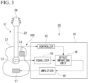
- the stringed musical instrument 10 includes a musical instrument body 11, strings 12, a pickup 13, a detection sensor 14, and a controller (control unit) 15. Also, the stringed musical instrument 10 of the present embodiment further includes an effect imparting unit 16 and a vibrator 17.
- the musical instrument body 11 includes a hollow part 21 and a neck 22.
- the hollow part 21 is formed in a box shape having therein a cavity S.
- the hollow part 21 has a front plate 23, a back plate 24, and a side plate 25.
- the front plate 23 and the back plate 24 are each formed in a flat plate shape.
- the front plate 23 and the back plate 24 are arranged spaced apart from one another in the plate thickness direction thereof.
- the side plate 25 extends from the circumferential edge of the back plate 24 to the circumferential edge of the front plate 23.
- the front plate 23, the back plate 24, and the side plate 25 form the hollow part 21 having therein the cavity S.
- a sound hole 26 (sound chamber) penetrating therethrough in the plate thickness direction of the front plate 23.
- the sound hole 26 communicates the cavity S of the hollow part 21 with the space outside the hollow part 21.
- a tailpiece 27 for fastening a first end of each string 12 in the lengthwise direction.
- the neck 22 extends in a direction away from the hollow part 21. At a distal end of the neck 22 there is provided a headstock (head, peghead) 28 for winding up a second end side of each string 12 in the lengthwise direction.
- headstock head, peghead
- the strings 12 are strung over the hollow part 21 and the neck 22. Specifically, the first end of each string 12 is fastened to the tailpiece 27 on the hollow part 21, and the second end of each string 12 is wound at the headstock 28. As a result, the strings 12 are strung between the tailpiece 27 and the head 28.
- a vibration transmitting unit 29 bridge
- vibration of the string 12 is transmitted to the front plate 23 via the vibration transmitting unit 29, thereby vibrating the front plate 23.
- the air inside the hollow part 21 (cavity S) resonates, and a sound is radiated to the outside of the hollow part 21.
- the pickup 13 detects vibration of the string 12 and outputs a string vibration signal according to the vibration of the string 12.
- the pickup 13 is arranged at the position on the front plate 23 where the sound hole 26 is formed, so as not to disturb the vibration of the front plate 23 associated with the vibration of the string 12.
- the embodiment of the disclosure is not limited to this example.
- the effect imparting unit 16 (effector) shown in FIG. 3 and FIG. 4 generates a sound signal (so-called wet sound) in which a musical or acoustic effect is imparted to a string vibration signal output from the pickup 13 (or equalizer 18 described later), and outputs the sound signal.
- the effect imparting unit 16 includes effect imparting elements 31 that each imparts a predetermined musical or acoustic effect, such as looper, distortion, wah-wah, reverb, or flanger.
- the effect imparting unit 16 may for example include only one effect imparting element 31.
- the effect imparting unit 16 includes a plurality of effect imparting elements 31 (31a to 31e) that each impart a different effect.
- the effect of the looper (effect imparting element 31a), which is one of the effect imparting elements 31, switches between start and stop of sound recording to thereby record a sound signal on the basis of an input string vibration signal or repeatedly reproduce a recorded sound signal.
- the effect imparting unit 16 includes a mixing circuit 32.
- the mixing circuit 32 mixes or selects, at an arbitrary ratio, output signals output from the effect elements according to the input string vibration signal input to the effect imparting unit 16 (wet sound) and a string vibration signal not passing through the effect elements (dry sound), and outputs the mixed or selected signals as a sound signal to an external unit (vibrator 17 or amplifier 19 described later) of the effect imparting unit 16.
- the effect imparting unit 16 is attached to the musical instrument body 11.
- the effect imparting unit 16 may be stored, for example, in a storage part 41 attached to the hollow part 21 as shown in FIG. 1 .
- the vibrator 17 is attached to the hollow part 21 of the musical instrument body 11.
- the vibrator 17 vibrates the hollow part 21 on the basis of a sound signal output from the effect imparting unit 16 according to the string vibration signal.
- the vibrator 17 vibrates the hollow part 21, the sound to which the effect is imparted by the effect imparting unit 16 is radiated to the outside of the hollow part 21.
- the vibrator 17 may be an electro-acoustic transducer of a commonly known voice coil type or of any other type.
- the vibrator 17 may be attached, for example, to the back plate 24 or the side plate 25.
- the vibrator 17 is attached to the front plate 23.
- the vibrator 17 is attached to an inner surface 23b of the front plate 23.
- the vibrator 17 is located in a region on the front plate 23 away from the peripheral region of the sound hole 26 (that is, away from the region where the detection sensor 14 is arranged).
- the vibrator 17 is located in a region of the hollow part 21 such that the sound hole 26 and the tailpiece 27 are sandwiched between the vibrator 17 and the neck 22.
- the stringed musical instrument 10 of the present embodiment further includes an equalizer 18 and an amplifier 19.
- the equalizer 18 adjusts the frequency characteristics of a string vibration signal output from the pickup 13.
- the equalizer 18 adjusts the frequency characteristics of the string vibration signal so as to emphasize, for example, a frequency region (for example, a harmonic component) higher than the fundamental tone frequency region of the string 12.
- the equalizer 18 outputs to the effect imparting unit 16 the string vibration signal the frequency characteristics of which have been adjusted.
- the amplifier 19 amplifies a sound signal output from the effect imparting unit 16 and outputs it to the vibrator 17.
- the equalizer 18 and the amplifier 19 are attached to the musical instrument body 11.
- the equalizer 18 and the amplifier 19 may be stored, for example, in the storage part 41 shown in FIG. 1 .
- the detection sensor 14 is attached to the musical instrument body 11.
- the detection sensor 14 outputs a detection signal according to a force applied to the musical instrument body 11.
- the detection sensor 14 according to the present invention is a deflection detection sensor 14 (for example, a strain gauge) that detects a deflection in the musical instrument body 11 when a force is applied to the musical instrument body 11.
- the detection sensor 14 may be, for example, a pressure sensor that detects a pressure applied to the musical instrument body 11.
- the detection sensor 14 may be, for example, an electrostatic sensor (capacitive touch sensor) that detects a touch applied by the player applied to the musical instrument body 11.
- the detection sensor 14 is attached to a part of the hollow part 21.
- the detection sensor 14 may be attached, for example, to the back plate 24 or the side plate 25.
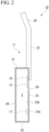
- the detection sensor 14 is attached to the front plate 23 as shown in FIG. 1 and FIG. 2 .
- the detection sensor 14 is attached to the inner surface 23b of the front plate 23.
- the detection sensor 14 is located in the peripheral region of the sound hole 26 on the front plate 23. In FIG. 1
- the detection sensor 14 is located on the right side of the strings 12 and the sound hole 26 when the stringed musical instrument 10 is viewed from the front (that is, when the stringed musical instrument 10 is viewed from the direction perpendicular to the front plate 23).
- the detection sensor 14 may be located on the left side, for example.
- the peripheral region of the sound hole 26 is a region where the player's fingers (player's hand and fingers) are primarily positioned when the player plays the stringed musical instrument 10 by plucking the strings 12 on the stringed musical instrument 10, which is a guitar. That is, it is sufficient that the detection sensor 14 is configured as a sensor that can detect a deflection in the musical instrument body 11 and is attached to the hollow part 21.
- the stringed musical instrument 10 of the present embodiment further includes a recognized part 50.
- the recognized part 50 is provided on the outer surface of the hollow part 21.
- the recognized part 50 is provided on the outer surface 23a of the front plate 23 of the hollow part 21.
- the recognized part 50 indicates the position of the detection sensor 15 that is provided on the inner surface of the hollow part 21.
- the recognized part 50 has a role of making the player visually or tactually recognize the position of the detection sensor 14.
- the recognized part 50 is provided, among the outer surface of the hollow part 21, at least an area to which a detection signal according to the force applied to the hollow part 21 is output. Therefore, for example, the recognized part 50 may be provided near the detection sensor 14 to the extent that they are not overlapped with each other when seen from the outside of the hollow part 21. Moreover, for example, the recognized part 50 may be provided at a position such that it is partially overlapped with (partially covers) the detection sensor 14 when seen from the outside of the hollow part 21. In the example shown in FIG. 1 , the recognized part 50 is provided at a position such that it overlaps with (covers) all of the detection sensor 14 when seen from the outside of the hollow part 21.
- the size of the recognized part 50 is larger than the size of the detection sensor 14 when seen from the outside of the hollow part 21; however, the disclosure is not limited to this example.
- the size of the recognized part 50 may be smaller than the size of the detection sensor 14 when seen from the outside of the hollow part 21.
- the shape of the recognized part 50 in planar view is a rectangular shape that is similar to that of the detection sensor 14 when seen from the outside of the hollow part 21; however, the disclosure is not limited to this example.
- the recognized part 50 may be formed in an arbitrary shape.
- the recognized part 50 may be a sticker attached to the outer surface of the hollow part 21, for example.
- the recognized part 50 is a sticker
- a stacker which serves as the recognized part 50 may be opaque, translucent or transparent.
- characters, symbols, patterns, pictures, or the like may be formed on the sticker by printing or the like.
- surface treatment may be applied to the sticker so that its surface roughness is different from that of the outer surface of the hollow part 21, for example.
- the sticker may be a texture sticker which is formed by digging characters, symbols, patterns, pictures, or the like, for example.
- the recognized part 50 When the recognized part 50 is a sticker, the recognized part 50 can be provided on the outer surface of the hollow part 21 easily at low cost as compared with the case where the recognized part 50 is a decal, an inlay, or a branding iron described later. Moreover, in this case, the recognized part 50 can be easily removed (peeled) from the hollow part 21.
- the recognized part 50 may be a decal or an inlay that is provided on the outer surface of the hollow part 21, for example.
- the recognized part 50 may be a branding iron formed on the outer surface of the hollow part 21, for example.
- An inlay has a structure in which a digging is formed in the outer surface of the hollow part 21 and another material (for example, wood or shell) is fitted into the digging.
- a performer of the stringed musical instrument 10 can mainly visually recognize the position of the detection sensor 14.
- the recognized part 50 is a decal, an inlay, or a branding iron, the appearance design of the stringed musical instrument 10 can be improved as compared with the sticker.
- the recognized part 50 may be formed by various printing methods such as stamp printing or sticker printing that is directly applied to the outer surface of the hollow part 21.
- a player of the stringed musical instrument 10 can recognize the position of the detection sensor 14 mainly visually.
- the recognized part 50 is formed by printing, it is possible to improve the degree of freedom in design of characters, symbols, patterns, pictures, or the like.
- the controller 15 shown in FIG. 3 and FIG. 4 is attached to the musical instrument body 11. As with the effect imparting unit 16, the controller 15 may be stored, for example, in the storage part 41 shown in FIG. 1 . As shown in FIG. 3 and FIG.
- the controller 15 on the basis of a detection signal output from the detection sensor 14, the controller 15 outputs a control signal for controlling the operation of the effect imparting unit 16, to the effect imparting unit 16.
- the controller 15 may output different types of control signals from the controller 15, depending, for example, on the number of times a force is applied to the musical instrument body 11 or the length of time a force is applied to the musical instrument body 11.
- the controller 15 outputs a control signal according to the magnitude of the amplitude (intensity) of a detection signal output from the detection sensor 14 or the height of the frequency of the detection signal. Specifically, the controller 15 outputs a control signal if the amplitude of a detection signal is greater than the maximum amplitude of the front plate 23 (musical instrument body 11) when a sound is radiated from the stringed musical instrument 10. Also, the controller 15 outputs a control signal if the frequency of a detection signal is lower than the lowest frequency of the front plate 23 (musical instrument body 11) when a sound is radiated from the stringed musical instrument 10. As a result, it is possible to suppress or prevent a control signal from being output from the controller 15 as a result of simply radiating a sound from the stringed musical instrument 10.
- the control signal output from the controller 15 may, for example, be a signal for switching ON/OFF of the effect imparting unit 16 (effect imparting element 31).
- the control signal output from the controller 15 may, for example, be a signal for switching between start and stop of sound recording performed by the looper (effect imparting element 31a), which is one of the effect imparting elements 31.
- control signal output from the controller 15 may be a signal that adjusts the strength or magnitude of an effect imparted to a string vibration signal according to the magnitude of the force applied to the front plate 23 (musical instrument body 11), for example.
- the magnitude of a distortion effect, a wah-wah effect, a reverb effect, or a flanger effect, or the magnitude of an arming (tremolo arm) effect may be adjusted according to the magnitude of the force applied to the front plate 23 (instrument body 11).
- the effect imparting unit 16 of the present embodiment includes a plurality of effect imparting elements 31 shown in FIG. 4 .
- the effect imparting unit 16 further includes a selector 33 for selecting to which of the effect imparting elements 31 is to be input a control signal output from the controller 15.
- the selector 33 may be operated according to, for example, a control signal output from the controller 15, or may be operated by an operation input by means of an operating element (not shown in the drawings), which is provided separately.
- the storage unit 41 shown in FIG. 1 may also store, in addition to the aforementioned controller 15, effect imparting unit 16, equalizer 18, and amplifier 19, a power supply for supplying electric power to these electrical components, and various operating elements such as an operating element for the selector 33 and a power supply switch.
- the detection sensor 14 attached to the musical instrument body 11 functions as an operating element for controlling the operation of the effect imparting unit 16. That is to say, the player of the stringed musical instrument 10 can control the operation of the effect imparting unit 16 by applying a force to the musical instrument body 11 (for example, bending the surface of the hollow part 21 of hitting or touching the surface of the hollow part 21). As a result, it is possible to control the operation of the effect imparting unit 16 without moving the positions of the player's fingers far from the strings 12. Therefore, the player can easily control the effect imparting unit 16 even while playing the stringed musical instrument 10.
- the detection sensor 14 is attached to a part of the hollow part 21 of the musical instrument body 11. Accordingly, the player can easily control the operation of the effect imparting unit 16 by pressing a part of the hollow part 21 with their arm or fingers to apply a pressure to a part of the surface of the hollow part 21 or to bend a part of the surface of the hollow part 21, or alternatively by hitting or touching a part of the surface of the hollow part 21. Furthermore, when the player plays the stringed musical instrument 10 by plucking the strings 12, the player's arm and fingers generally overlap the hollow part 21. By applying a force to the front plate 23 of the hollow part 21 in this state using the player's arm and fingers, the player can easily control the operation of the effect imparting unit 16 with almost no need for moving the positions of the arm and fingers when playing the stringed musical instrument 10.
- the detection sensor 14 is attached to the front plate 23 of the hollow part 21. Therefore, the player can bend the front plate 23 to control the operation of the effect imparting unit 16 by simply pressing the front plate 23 with their own fingers.
- the player's fingers are generally positioned above the front plate 23. Therefore, the player can easily control the operation of the effect imparting unit 16 with almost no need for moving the positions of the fingers when playing the stringed musical instrument 10.
- the detection sensor 14 is attached to the inner surface of the hollow part 21. As a result, it is possible to prevent degradation in the appearance design of the stringed musical instrument 10 associated with the detection sensor 14 being attached to the hollow part 21.
- the vibrator 17 attached to the hollow part 21 vibrates the hollow part 21 on the basis of a sound signal output from the effect imparting unit 16 according to the string vibration signal from the pickup 13.
- a sound having a musical or acoustic effect imparted thereto can be produced in the stringed musical instrument 10 (hollow part 21).
- the effect imparting unit 16 is attached to the musical instrument body 11.
- the stringed musical instrument 10 alone can produce a sound having an effect imparted thereto by the effect imparting unit 16.
- the effect of such a configuration is especially useful when the stringed musical instrument 10 has an acoustic guitar-like appearance. This point will be described below.
- the controller 15 of the stringed musical instrument 10 and the effect imparting unit 16 need to be electrically connected by a connection cable or the like.
- a typical acoustic guitar has no connection cable connected thereto, and therefore, an appearance of the stringed musical instrument 10 having a connection cable connected thereto would differ from that of a typical acoustic guitar and be unnatural.
- the effect imparting unit 16 is attached to the musical instrument body 11, there is no need for connecting a connection cable to the stringed musical instrument 10, and as a result, the appearance of the stringed musical instrument 10 can be made similar to that of a typical acoustic guitar.
- the effect imparting unit 16 includes a looper.
- a control signal output from the controller 15 includes a signal for switching between start and stop of sound recording performed by the looper. Accordingly, the player can easily switch between start and stop of sound recording performed by the looper without moving the positions of fingers far from the strings 12 (that is, without disturbing the performance of the stringed musical instrument 10). That is to say, the player can easily take advantage of the function of the looper.
- the stringed musical instrument 10 of the present embodiment includes the recognized part 50 that is provided on the outer surface of the hollow part 21 and that indicates the position of the detection sensor 50. Therefore, even if a player of the stringed musical instrument 10 cannot visually recognize the detection sensor 14 from the outside of the hollow part 21, the position of the detection sensor 50 can be grasped by the recognized part 50. Therefore, it is possible to suppress or prevent the player of the stringed musical instrument 10 from failing to operate the detection sensor 14. Failure to operate the detection sensor 14 by the player means that, for example, even if the player pushes the hollow part 21, the force is not transmitted to the detection sensor 14 and the detection signal is not output from the detection sensor 14.
- a stringed musical instrument 10A may include an external output unit 51.
- the external output unit 51 outputs a control signal output from the controller 15 to the effect imparting unit 16 provided outside the musical instrument body 11.
- the external output unit 51 may be an external connection terminal for establishing a wired connection to the effect imparting unit 16, or may be a wireless communication unit for establishing a wireless connection to the effect imparting unit 16.
- the effect imparting unit 16 can be provided separately from the stringed musical instrument 10A, and it is therefore possible to select any type of effect imparting unit 16 for use.
- the detection sensor 14 may be attached, for example, to the neck 22.
- the detection sensor 14 it is possible, while playing the stringed musical instrument 10, for the player to cause the detection sensor 14 to output a detection signal by bending the neck 22 or pressing a portion of the neck 22 provided with the detection sensor 14, to apply a force to the neck 22. That is to say, even in a case where the detection sensor 14 is provided on the neck 22, the player can still easily control the effect imparting unit 16 while playing the stringed musical instrument 10.
- One embodiment of the present disclosure may also be an acoustic effect device 100 (see FIG. 3 and FIG. 5 ) that includes at least the pickup 13, the detection sensor 14, and the controller 15, and is used for the stringed musical instrument 10.
- the acoustic effect device 100 may further include one or both of the vibrator 17 and the effect imparting unit 16. Also, the acoustic effect device 100 may include the equalizer 18 and the amplifier 19.
- the existing stringed musical instrument can have functions similar to those of the stringed musical instruments 10, 10A of the embodiment described above.
- the detection sensor 14 of the acoustic effect device 100 to the musical instrument body 11 of an existing stringed musical instrument, the detection sensor 14 functions as an operating element for controlling the operation of the effect imparting unit 16.
- the player of the stringed musical instrument 10 can control the operation of the effect imparting unit 16 by applying a force to the musical instrument body 11 (for example, by bending, hitting, or touching the hollow part 21 or the neck 22).
- the part of the player that applies a force to a part of the stringed musical instrument in order to output a detection signal from the detection sensor 14 may be a part other than their hand (for example, arm, elbow, abdomen, waist, thigh, and so forth).
- the detection sensor 14 is operated by the player's hand, and the detection sensor 14 is attached to the front plate 23 of the hollow part 21 accordingly.
- the detection sensor 14 may be provided in a portion of the stringed musical instrument with which the player's elbow is likely to come into contact (for example, a predetermined position on the front plate 23).
- the player's abdomen, waist, or thigh may apply a force to the back plate 24 or the side plate 25, which is a part of the stringed musical instrument.
- One embodiment of the present disclosure can also be perceived as a detection sensor outputting a detection signal according to the player's operation performed with respect to the front plate 23 or the back plate 24 of the hollow part 21 of the musical instrument body 11.
- the "player's operation performed with respect to the front plate 23 or the back plate 24" in one embodiment of the present disclosure refers to the operation described in the above embodiment, that is, the player bending the front plate 23 or the back plate 24 of the hollow part 21, hitting the front plate 23 of the back plate 24, while in an alternative departing from the invention, the player's operation may refer to touching the front plate 23 or the back plate 24hollow part, or moving closer to of moving away from the front plate 23 or the back plate 24.
- an electrostatic sensor may be used as a sensor for detecting the motion of a portion of the player such as their hand moving closer thereto or moving away therefrom.
- an electrostatic sensor capactive touch sensor
- a membrane switch can also be used as a sensor for detecting the motion of contacting with a portion of the player, such as a hand.
- the "player's operation performed with respect to the front plate 23 or the back plate 24" described above may also include the motion of the player moving a portion of their body, such as a hand, closer to or away from the front plate 23 or the back plate 24.
- an electrostatic sensor capactive touch sensor
- a membrane switch is attached to the front plate 23 or the back plate 24 of the hollow part 21
- the above-mentioned "player's operation performed with respect to the front plate 23 or the back plate 24" may include the motion of the player touching the front plate 23 or the back plate 24 with a portion of their body such as a hand.
- the electrostatic sensor may detect the motion of the player moving a portion of their body, such as a hand or an arm, closer to or away from the side plate 25 instead of the front plate 23 or the back plate 24, or in addition to the front plate 23 and the back plate 24.
- an electrostatic sensor (capacitive touch sensor) or a membrane switch may detect the motion of the player touching the side plate 25 with a portion of their body, such as a hand or an arm, to instead of the front plate 23 or the back plate 24, or in addition to the front plate 23 and the back plate 24.
- the detection sensor 14 is provided inside (inner surface) of the hollow part 2.
- the detection sensor 14 is attached to the hollow part 21 as a sensor that can detect the operation of the player.
- One embodiment of the present disclosure may be applied not only to an acoustic guitar that includes a hollow part 21 having therein a cavity S, but also to a guitar in which the hollow part thereof does not produce resonant sound on the basis of the vibration of strings (such as an electric guitar or an electric bass, which does not have a cavity inside the hollow part thereof, or a silent guitar (registered trademark), which includes a hollow part composed of a frame).
- the detection sensor may be provided, for example, in the vicinity of the pickup, and for a guitar that includes a hollow part composed of a frame, the detection sensor may be provided, for example, on the frame.
- One embodiment of the present disclosure is applicable not only to a guitar having a hollow part and a neck, but also to a stringed musical instrument having at least a musical instrument body and a string attached to the musical instrument body, such as a violin, a viola, a cello, or a contrabass.
- a player can easily control an effect imparting unit even while playing a stringed musical instrument.
Landscapes
- Engineering & Computer Science (AREA)
- Physics & Mathematics (AREA)
- Acoustics & Sound (AREA)
- Multimedia (AREA)
- Power Engineering (AREA)
- Nonlinear Science (AREA)
- Signal Processing (AREA)
- Electrophonic Musical Instruments (AREA)
- Stringed Musical Instruments (AREA)
Claims (8)
- Saitenmusikinstrument (10), umfassend:einen Musikinstrumentenkörper (11), der so konfiguriert ist, dass eine Saite daran angebracht ist;einen Tonabnehmer (13), der zu Folgendem konfiguriert ist: i) Erfassen der Saitenvibration und ii) Ausgeben eines Saitenvibrationssignals entsprechend der Vibration;einen Erfassungssensor (14), der: i) am Musikinstrumentenkörper angebracht und ii) so konfiguriert ist, dass er ein Erfassungssignal entsprechend einer auf den Musikinstrumentenkörper ausgeübten Kraft ausgibt; undeine Steuereinheit (15), die an dem Musikinstrumentenkörper angebracht ist und so konfiguriert ist, dass sie auf der Grundlage des Erfassungssignals ein Steuersignal ausgibt, das so konfiguriert ist, dass es einen Betrieb einer Effektvermittlereinheit steuert, die so konfiguriert ist, dass sie dem Saitenvibrationssignal einen Effekt vermittelt, wobeider Musikinstrumentenkörper einen hohlen Teil (21) einschließt, der eine Frontplatte (23), eine Rückplatte (24) und eine Seitenplatte (25) aufweist, unddas Saitenmusikinstrument dadurch gekennzeichnet ist, dassder Erfassungssensor an der inneren Oberfläche (23b) der Frontplatte im Inneren des hohlen Teils angebracht und so konfiguriert ist, dass er eine Durchbiegung des Musikinstrumentenkörpers erfasst.
- Saitenmusikinstrument nach Anspruch 1, weiter umfassend:
einen Vibrator (17), der an dem hohlen Teil des Musikinstrumentenkörpers angebracht ist, wobei der Vibrator so konfiguriert ist, dass er den hohlen Teil auf der Grundlage eines Tonsignals, das von der Effektvermittlereinheit entsprechend dem Saitenvibrationssignal ausgegeben wird, in Vibration versetzt. - Saitenmusikinstrument nach einem der Ansprüche 1 bis 2, wobei die Effektvermittlereinheit am Musikinstrumentenkörper angebracht ist.
- Saitenmusikinstrument nach einem der Ansprüche 1 bis 2, weiter umfassend:
eine externe Ausgabeeinheit (51), die so konfiguriert ist, dass sie das Steuersignal an die außerhalb des Musikinstrumentenkörpers bereitgestellte Effektvermittlereinheit ausgibt. - Saitenmusikinstrument nach einem der Ansprüche 1 bis 4, wobei
die Effektvermittlereinheit einen Looper einschließt, und
das von der Steuereinheit ausgegebene Steuersignal ein Signal einschließt, das so konfiguriert ist, dass es zwischen dem Starten und dem Stoppen der Tonaufnahme durch den Looper umschaltet. - Akustische Effektvorrichtung (100), die für ein Saitenmusikinstrument verwendet wird, umfassend:einen Tonabnehmer (13), der zu Folgendem konfiguriert ist: i) Erfassen der Vibration einer Saite des Saitenmusikinstruments und ii) Ausgeben eines Saitenvibrationssignals entsprechend der Vibration;einen Erfassungssensor (14), der so konfiguriert ist, dass er am Musikinstrumentenkörper des Saitenmusikinstruments angebracht ist und ein Erfassungssignal entsprechend der auf den Musikinstrumentenkörper ausgeübten Kraft ausgibt; undeine Steuereinheit (15), die so konfiguriert ist, dass sie auf der Grundlage des Erfassungssignals ein Steuersignal ausgibt, das so konfiguriert ist, dass es einen Betrieb einer Effektvermittlereinheit steuert, die so konfiguriert ist, dass sie dem Saitenvibrationssignal einen Effekt vermittelt,wobeider Musikinstrumentenkörper einen hohlen Teil (21) einschließt, der eine Frontplatte (23), eine Rückplatte (24) und eine Seitenplatte (25) aufweist, und dadurch gekennzeichnet ist, dassder Erfassungssensor weiter so konfiguriert ist, dass er an der inneren Oberfläche (23b) der Frontplatte innerhalb des hohlen Teils angebracht ist und eine Durchbiegung des Musikinstrumentenkörpers erfasst.
- Saitenmusikinstrument (10), umfassend:einen Musikinstrumentenkörper (11), der so konfiguriert ist, dass eine Saite daran angebracht ist;einen Tonabnehmer (13), der zu Folgendem konfiguriert ist: i) Erfassen der Saitenvibration und ii) Ausgeben eines Saitenvibrationssignals entsprechend der Vibration;einen Erfassungssensor (14), der so konfiguriert ist, dass er ein Erfassungssignal entsprechend der Betätigung eines Spielers in Bezug auf eine Frontplatte (23) oder eine Rückplatte (24) eines hohlen Teils des Musikinstrumentenkörpers ausgibt; undeine Steuereinheit (15), die an dem Musikinstrumentenkörper angebracht ist und so konfiguriert ist, dass sie auf der Grundlage des Erfassungssignals ein Steuersignal ausgibt, das so konfiguriert ist, dass es einen Betrieb eines Effekts steuert, der so konfiguriert ist, dass er dem Saitenvibrationssignal einen Effekt vermittelt,das Saitenmusikinstrument dadurch gekennzeichnet ist, dassder Erfassungssensor an der inneren Oberfläche (23b) der Frontplatte im Inneren des hohlen Teils angebracht und so konfiguriert ist, dass er eine Durchbiegung des Musikinstrumentenkörpers erfasst.
- Saitenmusikinstrument nach Anspruch 1, wobei
das Saitenmusikinstrument weiter einen erkannten Teil (50) umfasst, der auf einer äußeren Oberfläche des hohlen Teils angebracht ist und der eine Position des Erfassungssensors anzeigt.
Applications Claiming Priority (2)
| Application Number | Priority Date | Filing Date | Title |
|---|---|---|---|
| JP2021049408 | 2021-03-24 | ||
| JP2022024166A JP7782298B2 (ja) | 2021-03-24 | 2022-02-18 | 弦楽器及び音響効果装置 |
Publications (2)
| Publication Number | Publication Date |
|---|---|
| EP4064269A1 EP4064269A1 (de) | 2022-09-28 |
| EP4064269B1 true EP4064269B1 (de) | 2025-01-08 |
Family
ID=80819597
Family Applications (1)
| Application Number | Title | Priority Date | Filing Date |
|---|---|---|---|
| EP22162935.5A Active EP4064269B1 (de) | 2021-03-24 | 2022-03-18 | Saitenmusikinstrument und akustische effektvorrichtung |
Country Status (4)
| Country | Link |
|---|---|
| US (2) | US12367855B2 (de) |
| EP (1) | EP4064269B1 (de) |
| JP (1) | JP2026026174A (de) |
| CN (1) | CN115132157B (de) |
Families Citing this family (1)
| Publication number | Priority date | Publication date | Assignee | Title |
|---|---|---|---|---|
| CN115132157B (zh) * | 2021-03-24 | 2025-10-10 | 雅马哈株式会社 | 弦乐器及音响效果装置 |
Family Cites Families (34)
| Publication number | Priority date | Publication date | Assignee | Title |
|---|---|---|---|---|
| US4028977A (en) * | 1975-11-17 | 1977-06-14 | John Joseph Ryeczek | Optoelectronic sound amplifier system for musical instruments |
| US4817484A (en) * | 1987-04-27 | 1989-04-04 | Casio Computer Co., Ltd. | Electronic stringed instrument |
| US5731535A (en) * | 1997-01-14 | 1998-03-24 | Kaman Music Corporation | Proximity sensitive control circuit for electrical musical instrument |
| JP2000148148A (ja) * | 1998-11-10 | 2000-05-26 | Yamaha Corp | 弦楽器 |
| FR2792747B1 (fr) * | 1999-04-22 | 2001-06-22 | France Telecom | Dispositif d'acquisition et de traitement de signaux pour la commande d'un appareil ou d'un processus |
| US6791022B2 (en) * | 2001-03-15 | 2004-09-14 | Philip Shepard Green | Stringed musical instrument |
| US20050087062A1 (en) * | 2003-10-23 | 2005-04-28 | Yamaya Kiyohiko | Method of processing sounds from stringed instrument and pickup device for the same |
| US7135638B2 (en) * | 2003-11-25 | 2006-11-14 | Lloyd R. Baggs | Dynamic magnetic pickup for stringed instruments |
| US7235734B2 (en) * | 2003-12-16 | 2007-06-26 | Taylor-Listug, Inc. | Sensor array for a musical instrument |
| TWI298482B (en) * | 2005-04-28 | 2008-07-01 | Yamaha Corp | Stringed musical instrument, transducer for the same and its mounting structure on the same |
| US8093482B1 (en) * | 2008-01-28 | 2012-01-10 | Cypress Semiconductor Corporation | Detection and processing of signals in stringed instruments |
| US8173887B2 (en) * | 2008-10-07 | 2012-05-08 | Zivix Llc | Systems and methods for a digital stringed instrument |
| US8633370B1 (en) * | 2011-06-04 | 2014-01-21 | PRA Audio Systems, LLC | Circuits to process music digitally with high fidelity |
| EP2633517B1 (de) * | 2010-10-28 | 2019-01-02 | Gibson Brands, Inc. | Drahtlose e-gitarre |
| JP5716409B2 (ja) * | 2011-01-18 | 2015-05-13 | ヤマハ株式会社 | 楽器 |
| JP5929375B2 (ja) * | 2011-03-24 | 2016-06-08 | ヤマハ株式会社 | 楽器用振動センサ、ピックアップサドルおよび楽器 |
| US8735710B2 (en) * | 2012-02-10 | 2014-05-27 | Roland Corporation | Electronic stringed instrument having effect device |
| US9000287B1 (en) * | 2012-11-08 | 2015-04-07 | Mark Andersen | Electrical guitar interface method and system |
| US9508333B2 (en) * | 2013-01-17 | 2016-11-29 | Northeastern University | Magnetoelectric pickup element for detecting oscillating magnetic fields |
| JP6387586B2 (ja) * | 2013-04-15 | 2018-09-12 | カシオ計算機株式会社 | 電子弦楽器 |
| US9601100B1 (en) * | 2015-03-09 | 2017-03-21 | George J. Dixon | Magnetic pickup with external tone shaper |
| WO2016152219A1 (ja) * | 2015-03-24 | 2016-09-29 | ヤマハ株式会社 | 付加的振動音を発生可能な楽器及び方法 |
| US9536504B1 (en) * | 2015-11-30 | 2017-01-03 | International Business Machines Corporation | Automatic tuning floating bridge for electric stringed instruments |
| CN110767205B (zh) * | 2016-01-20 | 2023-08-29 | 雅马哈株式会社 | 音响装置以及机械性振动生成方法 |
| US9899015B2 (en) * | 2016-02-10 | 2018-02-20 | Zivix Llc | Systems and methods for creating digital note information for a metal-stringed musical instrument |
| US9653055B1 (en) * | 2016-04-15 | 2017-05-16 | Steven B. Savage | Vibrato tailpiece and method of output signal control for stringed instruments |
| FR3054764B1 (fr) | 2016-07-28 | 2018-07-27 | B<>Com | Procede de decodage d'une image, procede de codage, dispositifs, equipement terminal et programmes d'ordinateurs associes |
| JP7218420B2 (ja) | 2017-03-14 | 2023-02-06 | 株式会社ジャパンディスプレイ | 光検出装置及び表示装置 |
| US10115379B1 (en) * | 2017-04-27 | 2018-10-30 | Gibson Brands, Inc. | Acoustic guitar user interface |
| GB2572129A (en) * | 2018-01-26 | 2019-09-25 | Tonik Sounds Ltd | Accessory for a musical instrument |
| KR102647201B1 (ko) * | 2019-06-06 | 2024-03-14 | 광저우 라바 뮤직 엘엘씨. | 사운드 픽업 장치, 현악기 및 사운드 픽업 장치 제어방법 |
| JP2021049408A (ja) | 2020-12-21 | 2021-04-01 | 株式会社ニコン | 清掃装置 |
| CN115132157B (zh) * | 2021-03-24 | 2025-10-10 | 雅马哈株式会社 | 弦乐器及音响效果装置 |
| JP2023044833A (ja) * | 2021-09-21 | 2023-04-03 | ヤマハ株式会社 | 楽器 |
-
2022
- 2022-03-14 CN CN202210249640.0A patent/CN115132157B/zh active Active
- 2022-03-18 EP EP22162935.5A patent/EP4064269B1/de active Active
- 2022-03-22 US US17/701,094 patent/US12367855B2/en active Active
-
2025
- 2025-06-20 US US19/244,408 patent/US20250316252A1/en active Pending
- 2025-11-26 JP JP2025203672A patent/JP2026026174A/ja active Pending
Also Published As
| Publication number | Publication date |
|---|---|
| JP2026026174A (ja) | 2026-02-16 |
| CN115132157A (zh) | 2022-09-30 |
| US20250316252A1 (en) | 2025-10-09 |
| US20220310052A1 (en) | 2022-09-29 |
| EP4064269A1 (de) | 2022-09-28 |
| US12367855B2 (en) | 2025-07-22 |
| CN115132157B (zh) | 2025-10-10 |
Similar Documents
| Publication | Publication Date | Title |
|---|---|---|
| EP3564947B1 (de) | Vorrichtung für ein rohrblattinstrument | |
| JPS5850391Y2 (ja) | 電気打楽器 | |
| US6800797B2 (en) | Method and apparatus for producing acoustical guitar sounds using an electric guitar | |
| JP4369847B2 (ja) | 弦楽器に於ける音の処理方法とそのピックアップ装置 | |
| EP3407345B1 (de) | Zur erzeugung von zusätzlichem vibrationsschall fähiges musikinstrument und verfahren dafür | |
| EP1600940B1 (de) | Aufnahmevorrichtung für gezupftes Saiteninstrument und gezupftes Saiteninstrument | |
| US20250316252A1 (en) | Stringed Musical Instrument and Acoustic Effect Device | |
| US6018120A (en) | Acoustic musical instrument of the violin family with piezo-electric pickup | |
| US20240203380A1 (en) | Musical instrument | |
| JP2025061927A (ja) | 検出システムおよび鍵盤装置 | |
| JP2006030406A (ja) | ピックアップ付き駒および弦楽器 | |
| US20200410969A1 (en) | Sound enhancing accessory for a musical instrument | |
| KR102006889B1 (ko) | 현악기 픽업 장치, 현악기 픽업 장치를 이용한 연주 정보 출력 방법, 및 현악기 | |
| JP7782298B2 (ja) | 弦楽器及び音響効果装置 | |
| JP7611460B2 (ja) | 側孔を有する管楽器と組み合わされ得る、空中音波を伝達するためのアセンブリ | |
| US6191346B1 (en) | Stringed instrument | |
| JP2000148148A (ja) | 弦楽器 | |
| JP2021192067A (ja) | 演奏補助具およびギター | |
| JPH036955Y2 (de) | ||
| JP2010066640A (ja) | 楽器 | |
| JP2579230Y2 (ja) | 電子弦楽器 | |
| JPS5850392Y2 (ja) | 電気ドラム | |
| JP2000250535A (ja) | 電気楽器 | |
| JPH08129378A (ja) | 電子弦楽器 | |
| JPH0375696A (ja) | 電子金管楽器 |
Legal Events
| Date | Code | Title | Description |
|---|---|---|---|
| PUAI | Public reference made under article 153(3) epc to a published international application that has entered the european phase |
Free format text: ORIGINAL CODE: 0009012 |
|
| STAA | Information on the status of an ep patent application or granted ep patent |
Free format text: STATUS: THE APPLICATION HAS BEEN PUBLISHED |
|
| AK | Designated contracting states |
Kind code of ref document: A1 Designated state(s): AL AT BE BG CH CY CZ DE DK EE ES FI FR GB GR HR HU IE IS IT LI LT LU LV MC MK MT NL NO PL PT RO RS SE SI SK SM TR |
|
| STAA | Information on the status of an ep patent application or granted ep patent |
Free format text: STATUS: REQUEST FOR EXAMINATION WAS MADE |
|
| 17P | Request for examination filed |
Effective date: 20221103 |
|
| RBV | Designated contracting states (corrected) |
Designated state(s): AL AT BE BG CH CY CZ DE DK EE ES FI FR GB GR HR HU IE IS IT LI LT LU LV MC MK MT NL NO PL PT RO RS SE SI SK SM TR |
|
| GRAP | Despatch of communication of intention to grant a patent |
Free format text: ORIGINAL CODE: EPIDOSNIGR1 |
|
| STAA | Information on the status of an ep patent application or granted ep patent |
Free format text: STATUS: GRANT OF PATENT IS INTENDED |
|
| RIC1 | Information provided on ipc code assigned before grant |
Ipc: G10H 1/00 20060101ALI20240711BHEP Ipc: G10H 3/18 20060101ALI20240711BHEP Ipc: G10H 1/18 20060101ALI20240711BHEP Ipc: G10H 1/055 20060101AFI20240711BHEP |
|
| INTG | Intention to grant announced |
Effective date: 20240805 |
|
| GRAS | Grant fee paid |
Free format text: ORIGINAL CODE: EPIDOSNIGR3 |
|
| GRAA | (expected) grant |
Free format text: ORIGINAL CODE: 0009210 |
|
| STAA | Information on the status of an ep patent application or granted ep patent |
Free format text: STATUS: THE PATENT HAS BEEN GRANTED |
|
| AK | Designated contracting states |
Kind code of ref document: B1 Designated state(s): AL AT BE BG CH CY CZ DE DK EE ES FI FR GB GR HR HU IE IS IT LI LT LU LV MC MK MT NL NO PL PT RO RS SE SI SK SM TR |
|
| REG | Reference to a national code |
Ref country code: GB Ref legal event code: FG4D |
|
| REG | Reference to a national code |
Ref country code: CH Ref legal event code: EP |
|
| REG | Reference to a national code |
Ref country code: DE Ref legal event code: R096 Ref document number: 602022009468 Country of ref document: DE |
|
| REG | Reference to a national code |
Ref country code: IE Ref legal event code: FG4D |
|
| PGFP | Annual fee paid to national office [announced via postgrant information from national office to epo] |
Ref country code: AT Payment date: 20250417 Year of fee payment: 4 |
|
| REG | Reference to a national code |
Ref country code: LT Ref legal event code: MG9D |
|
| REG | Reference to a national code |
Ref country code: NL Ref legal event code: MP Effective date: 20250108 |
|
| REG | Reference to a national code |
Ref country code: AT Ref legal event code: MK05 Ref document number: 1758874 Country of ref document: AT Kind code of ref document: T Effective date: 20250108 |
|
| PG25 | Lapsed in a contracting state [announced via postgrant information from national office to epo] |
Ref country code: NL Free format text: LAPSE BECAUSE OF FAILURE TO SUBMIT A TRANSLATION OF THE DESCRIPTION OR TO PAY THE FEE WITHIN THE PRESCRIBED TIME-LIMIT Effective date: 20250108 |
|
| PG25 | Lapsed in a contracting state [announced via postgrant information from national office to epo] |
Ref country code: RS Free format text: LAPSE BECAUSE OF FAILURE TO SUBMIT A TRANSLATION OF THE DESCRIPTION OR TO PAY THE FEE WITHIN THE PRESCRIBED TIME-LIMIT Effective date: 20250408 |
|
| PG25 | Lapsed in a contracting state [announced via postgrant information from national office to epo] |
Ref country code: PL Free format text: LAPSE BECAUSE OF FAILURE TO SUBMIT A TRANSLATION OF THE DESCRIPTION OR TO PAY THE FEE WITHIN THE PRESCRIBED TIME-LIMIT Effective date: 20250108 |
|
| PG25 | Lapsed in a contracting state [announced via postgrant information from national office to epo] |
Ref country code: ES Free format text: LAPSE BECAUSE OF FAILURE TO SUBMIT A TRANSLATION OF THE DESCRIPTION OR TO PAY THE FEE WITHIN THE PRESCRIBED TIME-LIMIT Effective date: 20250108 |
|
| PG25 | Lapsed in a contracting state [announced via postgrant information from national office to epo] |
Ref country code: NO Free format text: LAPSE BECAUSE OF FAILURE TO SUBMIT A TRANSLATION OF THE DESCRIPTION OR TO PAY THE FEE WITHIN THE PRESCRIBED TIME-LIMIT Effective date: 20250408 Ref country code: IS Free format text: LAPSE BECAUSE OF FAILURE TO SUBMIT A TRANSLATION OF THE DESCRIPTION OR TO PAY THE FEE WITHIN THE PRESCRIBED TIME-LIMIT Effective date: 20250508 |
|
| PG25 | Lapsed in a contracting state [announced via postgrant information from national office to epo] |
Ref country code: HR Free format text: LAPSE BECAUSE OF FAILURE TO SUBMIT A TRANSLATION OF THE DESCRIPTION OR TO PAY THE FEE WITHIN THE PRESCRIBED TIME-LIMIT Effective date: 20250108 |
|
| PG25 | Lapsed in a contracting state [announced via postgrant information from national office to epo] |
Ref country code: PT Free format text: LAPSE BECAUSE OF FAILURE TO SUBMIT A TRANSLATION OF THE DESCRIPTION OR TO PAY THE FEE WITHIN THE PRESCRIBED TIME-LIMIT Effective date: 20250508 Ref country code: LV Free format text: LAPSE BECAUSE OF FAILURE TO SUBMIT A TRANSLATION OF THE DESCRIPTION OR TO PAY THE FEE WITHIN THE PRESCRIBED TIME-LIMIT Effective date: 20250108 |
|
| PG25 | Lapsed in a contracting state [announced via postgrant information from national office to epo] |
Ref country code: GR Free format text: LAPSE BECAUSE OF FAILURE TO SUBMIT A TRANSLATION OF THE DESCRIPTION OR TO PAY THE FEE WITHIN THE PRESCRIBED TIME-LIMIT Effective date: 20250409 Ref country code: BG Free format text: LAPSE BECAUSE OF FAILURE TO SUBMIT A TRANSLATION OF THE DESCRIPTION OR TO PAY THE FEE WITHIN THE PRESCRIBED TIME-LIMIT Effective date: 20250108 |
|
| PG25 | Lapsed in a contracting state [announced via postgrant information from national office to epo] |
Ref country code: AT Free format text: LAPSE BECAUSE OF FAILURE TO SUBMIT A TRANSLATION OF THE DESCRIPTION OR TO PAY THE FEE WITHIN THE PRESCRIBED TIME-LIMIT Effective date: 20250108 |
|
| PG25 | Lapsed in a contracting state [announced via postgrant information from national office to epo] |
Ref country code: SE Free format text: LAPSE BECAUSE OF FAILURE TO SUBMIT A TRANSLATION OF THE DESCRIPTION OR TO PAY THE FEE WITHIN THE PRESCRIBED TIME-LIMIT Effective date: 20250108 |
|
| PG25 | Lapsed in a contracting state [announced via postgrant information from national office to epo] |
Ref country code: SM Free format text: LAPSE BECAUSE OF FAILURE TO SUBMIT A TRANSLATION OF THE DESCRIPTION OR TO PAY THE FEE WITHIN THE PRESCRIBED TIME-LIMIT Effective date: 20250108 |
|
| REG | Reference to a national code |
Ref country code: DE Ref legal event code: R097 Ref document number: 602022009468 Country of ref document: DE |
|
| PG25 | Lapsed in a contracting state [announced via postgrant information from national office to epo] |
Ref country code: DK Free format text: LAPSE BECAUSE OF FAILURE TO SUBMIT A TRANSLATION OF THE DESCRIPTION OR TO PAY THE FEE WITHIN THE PRESCRIBED TIME-LIMIT Effective date: 20250108 |
|
| PG25 | Lapsed in a contracting state [announced via postgrant information from national office to epo] |
Ref country code: MC Free format text: LAPSE BECAUSE OF FAILURE TO SUBMIT A TRANSLATION OF THE DESCRIPTION OR TO PAY THE FEE WITHIN THE PRESCRIBED TIME-LIMIT Effective date: 20250108 |
|
| PG25 | Lapsed in a contracting state [announced via postgrant information from national office to epo] |
Ref country code: CZ Free format text: LAPSE BECAUSE OF FAILURE TO SUBMIT A TRANSLATION OF THE DESCRIPTION OR TO PAY THE FEE WITHIN THE PRESCRIBED TIME-LIMIT Effective date: 20250108 Ref country code: EE Free format text: LAPSE BECAUSE OF FAILURE TO SUBMIT A TRANSLATION OF THE DESCRIPTION OR TO PAY THE FEE WITHIN THE PRESCRIBED TIME-LIMIT Effective date: 20250108 |
|
| REG | Reference to a national code |
Ref country code: CH Ref legal event code: H13 Free format text: ST27 STATUS EVENT CODE: U-0-0-H10-H13 (AS PROVIDED BY THE NATIONAL OFFICE) Effective date: 20251023 |
|
| PG25 | Lapsed in a contracting state [announced via postgrant information from national office to epo] |
Ref country code: RO Free format text: LAPSE BECAUSE OF FAILURE TO SUBMIT A TRANSLATION OF THE DESCRIPTION OR TO PAY THE FEE WITHIN THE PRESCRIBED TIME-LIMIT Effective date: 20250108 |
|
| PG25 | Lapsed in a contracting state [announced via postgrant information from national office to epo] |
Ref country code: SK Free format text: LAPSE BECAUSE OF FAILURE TO SUBMIT A TRANSLATION OF THE DESCRIPTION OR TO PAY THE FEE WITHIN THE PRESCRIBED TIME-LIMIT Effective date: 20250108 |
|
| PLBE | No opposition filed within time limit |
Free format text: ORIGINAL CODE: 0009261 |
|
| STAA | Information on the status of an ep patent application or granted ep patent |
Free format text: STATUS: NO OPPOSITION FILED WITHIN TIME LIMIT |
|
| PG25 | Lapsed in a contracting state [announced via postgrant information from national office to epo] |
Ref country code: LU Free format text: LAPSE BECAUSE OF NON-PAYMENT OF DUE FEES Effective date: 20250318 |
|
| REG | Reference to a national code |
Ref country code: BE Ref legal event code: MM Effective date: 20250331 |
|
| 26N | No opposition filed |
Effective date: 20251009 |
|
| PG25 | Lapsed in a contracting state [announced via postgrant information from national office to epo] |
Ref country code: BE Free format text: LAPSE BECAUSE OF NON-PAYMENT OF DUE FEES Effective date: 20250331 |
|
| PG25 | Lapsed in a contracting state [announced via postgrant information from national office to epo] |
Ref country code: CH Free format text: LAPSE BECAUSE OF NON-PAYMENT OF DUE FEES Effective date: 20250331 |
|
| PG25 | Lapsed in a contracting state [announced via postgrant information from national office to epo] |
Ref country code: IE Free format text: LAPSE BECAUSE OF NON-PAYMENT OF DUE FEES Effective date: 20250318 |
|
| PG25 | Lapsed in a contracting state [announced via postgrant information from national office to epo] |
Ref country code: IT Free format text: LAPSE BECAUSE OF FAILURE TO SUBMIT A TRANSLATION OF THE DESCRIPTION OR TO PAY THE FEE WITHIN THE PRESCRIBED TIME-LIMIT Effective date: 20250108 |
|
| PGFP | Annual fee paid to national office [announced via postgrant information from national office to epo] |
Ref country code: DE Payment date: 20260319 Year of fee payment: 5 |
|
| PGFP | Annual fee paid to national office [announced via postgrant information from national office to epo] |
Ref country code: FR Payment date: 20260323 Year of fee payment: 5 |