EP4063802B1 - Ultrasonic flowmeter - Google Patents
Ultrasonic flowmeter Download PDFInfo
- Publication number
- EP4063802B1 EP4063802B1 EP20888902.2A EP20888902A EP4063802B1 EP 4063802 B1 EP4063802 B1 EP 4063802B1 EP 20888902 A EP20888902 A EP 20888902A EP 4063802 B1 EP4063802 B1 EP 4063802B1
- Authority
- EP
- European Patent Office
- Prior art keywords
- flow path
- flow
- sub
- measurement
- ultrasonic
- Prior art date
- Legal status (The legal status is an assumption and is not a legal conclusion. Google has not performed a legal analysis and makes no representation as to the accuracy of the status listed.)
- Active
Links
Images


Classifications
-
- G—PHYSICS
- G01—MEASURING; TESTING
- G01F—MEASURING VOLUME, VOLUME FLOW, MASS FLOW OR LIQUID LEVEL; METERING BY VOLUME
- G01F1/00—Measuring the volume flow or mass flow of fluid or fluent solid material wherein the fluid passes through a meter in a continuous flow
- G01F1/66—Measuring the volume flow or mass flow of fluid or fluent solid material wherein the fluid passes through a meter in a continuous flow by measuring frequency, phase shift or propagation time of electromagnetic or other waves, e.g. using ultrasonic flowmeters
- G01F1/662—Constructional details
-
- G—PHYSICS
- G01—MEASURING; TESTING
- G01F—MEASURING VOLUME, VOLUME FLOW, MASS FLOW OR LIQUID LEVEL; METERING BY VOLUME
- G01F1/00—Measuring the volume flow or mass flow of fluid or fluent solid material wherein the fluid passes through a meter in a continuous flow
- G01F1/66—Measuring the volume flow or mass flow of fluid or fluent solid material wherein the fluid passes through a meter in a continuous flow by measuring frequency, phase shift or propagation time of electromagnetic or other waves, e.g. using ultrasonic flowmeters
- G01F1/667—Arrangements of transducers for ultrasonic flowmeters; Circuits for operating ultrasonic flowmeters
-
- G—PHYSICS
- G01—MEASURING; TESTING
- G01F—MEASURING VOLUME, VOLUME FLOW, MASS FLOW OR LIQUID LEVEL; METERING BY VOLUME
- G01F15/00—Details of, or accessories for, apparatus of groups G01F1/00 - G01F13/00 insofar as such details or appliances are not adapted to particular types of such apparatus
Definitions
- the present disclosure relates to an ultrasonic flowmeter that divides a measurement flow path into multilayer flow paths by partition plates to measure the flow rate of a measurement target fluid.
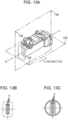
- FIGs. 13A to 13E are diagrams illustrating a conventional ultrasonic flowmeter disclosed in PTL 1.
- Fig. 13A is a perspective view of the conventional ultrasonic flowmeter.
- Fig. 13B is a view taken in the direction of arrow S in Fig. 13A.
- Fig. 13C is a view taken in the direction of arrow T in Fig. 13A .
- Fig. 13D is a cross sectional view taken along line 13D-13D of Fig. 13A .
- Fig. 13E is a cross sectional view taken along line 13E-13E of Fig. 13A .
- the ultrasonic flowmeter is disposed in measurement flow path 4 having a rectangular cross-section in which a pair of ultrasonic transducers respectively including first ultrasonic transducer 6 and second ultrasonic transducer 7 are disposed.
- Entrainment flow suppression sheet 8 having opening portions 9, 10 smaller than the openings of recessed portions 11, 12 is disposed in a path extending from the ultrasonic transmission surfaces of first ultrasonic transducer 6 and second ultrasonic transducer 7 to measurement flow path 4.
- Suppression sheet 8 can suppress attenuation of ultrasonic waves, suppress generation of vortex flows p and q in recessed portions 11, 12, which cause a measurement error, and secure the measurement accuracy.
- the flow paths through which a measurement target fluid flows have substantially the same rectangular cross sectional shapes. That is, when the total number of flow paths including measurement flow path 4 is three, the three flow paths have cross sectional shapes with the same width and height.
- the total number of flow paths is five by adding two flow paths. In this case, two flow paths having the same width and height as those of the existing flow paths are added. This poses a problem that an external size of the ultrasonic flowmeter is remarkably increased, and it is difficult to mount the ultrasonic flowmeter in a gas meter box housing the ultrasonic flowmeter.
- the total number of measurement flow paths 4 shown in Figs. 13B to 13D is four.
- An ultrasonic flowmeter includes a fluid flow path through which a measurement target fluid flows, a pair of ultrasonic transducers disposed upstream and downstream of an upper portion of the fluid flow path and configured to transmit and receive an ultrasonic signal, and a flow rate calculator configured to calculate a flow rate of the measurement target fluid based on a propagation time from when the ultrasonic signal transmitted from one of the pair of ultrasonic transducers propagates through the measurement target fluid to when the other of the pair of ultrasonic transducers receives the ultrasonic signal.
- the fluid flow path includes a main flow path including a plurality of divided flow paths obtained by dividing a flow path having a rectangular cross-section by the same width, and a sub flow path including an added flow path having a cross-section having the same width as that of the divided flow path and having a height lower than that of the divided flow path. Furthermore, flow rate calculator calculates the flow rate of the measurement target fluid flowing through the fluid flow path from the flow velocity or flow rate of the measurement target fluid obtained based on the propagation time.
- each rectangular added flow path of the sub flow path has the same width as the rectangular shape of each flow path of the measurement flow path and has a low height, the external size of the ultrasonic flowmeter can be made relatively compact, and highly accurate measurement can be implemented even for measurement of a measurement target fluid with a large flow rate.
- an ultrasonic flowmeter that can implement highly accurate measurement while having a compact outer shape when measuring a measurement target fluid of a larger flow rate.
- Fig. 1A is a perspective view of an ultrasonic flowmeter according to a first exemplary embodiment of the present disclosure.
- Fig. 1B is a view taken in a direction of arrow A in Fig. 1A.
- Fig. 1C is a view taken in the direction of arrow B in Fig. 1A .
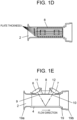
- Fig. 1D is a cross sectional view taken along line 1D-1D of Fig. 1A .
- Fig. 1E is a cross sectional view taken along line 1E-1E of Fig. 1A .
- Fig. 2 is an enlarged view of Fig. 1C .
- ultrasonic flowmeter 1 includes flow path body 19 in which fluid flow path 2 through which a measurement target fluid flows is configured.
- a pair of ultrasonic transducers including first ultrasonic transducer 6 and second ultrasonic transducer 7 that can transmit and receive ultrasonic signals are disposed upstream and downstream of an upper portion of fluid flow path 2.
- the ultrasonic flowmeter further includes flow rate calculator 21 that measures the flow velocity or flow rate of a fluid to be contacted based on the propagation time from when the ultrasonic signal transmitted from one of the pair of ultrasonic transducers including first ultrasonic transducer 6 and second ultrasonic transducer 7 propagates through a measurement target fluid to when the ultrasonic signal is received by the other ultrasonic transducer.
- measurement flow path 4 which is a main flow path having a rectangular flow cross-section, is divided by partition plates 20a, 20b, and 20c and constitutes a plurality of divided flow paths 5a, 5b, 5c, and 5d having same width w and same height h.
- the fluid flow path 2 is provided with sub flow paths 22a, 22b constituted with added flow paths 24a, 24b, 24c, and 24d which have rectangular cross-sections having same width w as that of divided flow paths 5a, 5b, 5c, and 5d constituting measurement flow path 4 and having height lower than height h of divided flow paths 5a, 5b, 5c, and 5d.
- Measurement flow path 4 as a main flow path and sub flow path 22a are divided by sub partition plate 23a
- measurement flow path 4 as a main flow path and sub flow path 22b are divided by sub partition plate 23b
- Sub flow path 22a is provided with added flow paths 24a, 24b which are divided by sub partition plate 23c and have rectangular cross-sections which have the same width w as that of divided flow paths 5a, 5b, 5c, and 5d and having a height lower than height h of divided flow paths 5a, 5b, 5c, and 5d.
- Sub flow path 22b is provided with added flow paths 24c, 24d which are divided by sub partition plate 23d and have rectangular cross-sections which have the same width w as that of divided flow paths 5a, 5b, 5c, and 5d and having a height lower than height h of divided flow paths 5a, 5b, 5c, and 5d.
- Flow path body 19 includes trumpet-shaped inlet portion 19a into which the measurement target fluid flows and outlet portion 19b from which the measurement target fluid flows out, and may have, for example, a structure made by resin injection molding.
- Partition plates 20a, 20b, and 20c and sub partition plates 23a, 23b, 23c, and 23d are made of, for example, stainless metal plates and have same plate thickness t, which is about 0.3 mm, as illustrated in Fig. 1D .
- Partition plates 20a, 20b, and 20c and sub partition plates 23a, 23b, 23c, and 23d are attached to flow path body 19.
- Fig. 3A is an exploded perspective view of a flow path body and each partition plate according to the first exemplary embodiment of the present disclosure.
- Fig. 3B is a cross sectional view taken along line 3B-3B of Fig. 3A .
- Fig. 3C is a view taken in the direction of arrow C in Fig. 3A .
- inflow-side fixing grooves 29a, 29b, 29c, 29d, 29e, 29f, and 29g and outflow-side fixing grooves 30a, 30b, 30c, 30d, 30e, 30f, and 30g are provided on the reflecting surface 25 side of a space through which the measurement target fluid flows.
- Reflecting surface 25 is a flat surface by which an ultrasonic signal transmitted from one of the pair of ultrasonic transducers including first ultrasonic transducer 6 and second ultrasonic transducer 7 is reflected to cause the ultrasonic signal to propagate through the measurement target fluid and reach the other ultrasonic transducer.
- inflow-side slits 27a, 27b, 27c, 27d, 27e, 29f, and 29g and outflow-side slits 28a, 28b, 28c, 28d, 28e, 28f, and 28g are provided on entrainment flow suppression sheet installation surface 26 side of flow path body 19.
- inflow-side fixing grooves 29a to 29g, outflow-side fixing grooves 30a to 30g, inflow-side slits 27a to 27g, and outflow-side slits 28a to 28g all have the same width and a thickness of, for example, about 0.32 mm, which is slightly larger than plate thicknesses t of partition plates 20a to 20c and sub partition plates 23a to 23d.
- two protruding portions 23e are provided as for the shapes of partition plates 20a to 20c and the sub partition plates 23a to 23d.
- partition plates 20a to 20c and sub partition plates 23a to 23d are attached to flow path body 19, as illustrated in Fig 3A , they are inserted from the entrainment flow suppression sheet installation surface 26 side.
- Protruding portions 23e of partition plates 20a to 20c and sub partition plates 23a to 23d are fitted into respective inflow-side fixing grooves 29a to 29g and respective outflow-side fixing grooves 30a to 30g, whereas the portions of the respective partition plates and the respective sub partition plates which are opposite to protruding portions 23e are sandwiched between inflow-side slits 27a to 27g and outflow-side slits 28a to 28g and fixed by clearance fit.
- partition plates 20a to 20c, and sub partition plates 23a to 23d are configured as separate parts and are fixed and integrated by clearance fit.
- partition plates 20a to 20c, sub partition plates 23a to 23d, and flow path body 19 may be configured to be integrally molded with resin.
- Fig. 4 is a perspective view of ultrasonic flowmeter 1 according to the first exemplary embodiment of the present disclosure.
- first ultrasonic transducer 6 and second ultrasonic transducer 7 are set at predetermined positions of resin ultrasonic transducer fixing body 31 and fixed by resin ultrasonic transducer fixtures 33.
- Projections 31a are provided on the ultrasonic transducer fixing body 31 side, and fitting holes 33a provided on the ultrasonic transducer fixture 33 side are fitted on the projections, thereby sandwiching and fixing first ultrasonic transducer 6 and second ultrasonic transducer 7 between ultrasonic transducer fixing body 31 and ultrasonic transducer fixtures 33.
- Signal lines 6a, 7a of first ultrasonic transducer 6 and second ultrasonic transducer 7 are connected to flow rate calculator 21.
- Ultrasonic transducer unit 32 assembled in this manner is attached to an upper portion of flow path body 19 through entrainment flow suppression sheet 8.
- Ultrasonic transducer fixing body 31 can be attached to flow path body 19 by, for example, thermal welding as long as both the components are made of a resin.
- divided flow paths 5a, 5b, 5c, and 5d of measurement flow path 4 each have a rectangular cross sectional shape having width w and height h and are interposed between partition plates 20a, 20b, and 20c having same plate thickness t.
- Added flow path 24a of sub flow path 22a has a rectangular cross sectional shape with width w and height h2.
- Added flow path 24b has a rectangular cross sectional shape with width w and height h1.
- Added flow path 24a and added flow path 24b sandwich sub partition plate 23c having plate thickness t.
- Added flow path 24d of sub flow path 22b has a rectangular cross sectional shape with width w and height h2.
- Added flow path 24c has a rectangular cross sectional shape with width w and height h1.
- h2 ⁇ h1 ⁇ h is set so that the flow passage cross-section of fluid flow path 2 falls within circle F indicated by the dotted line.
- Added flow path 24d and added flow path 24c sandwich sub partition plate 23d having plate thickness t.
- Measurement flow path 4 and sub flow path 22a sandwich sub partition plate 23a having plate thickness t.
- Measurement flow path 4 and sub flow path 22b sandwich sub partition plate 23b having plate thickness t.
- Sub flow path 22a and sub flow path 22b are arranged so as to be symmetric with respect to widthwise center line X and heightwise center line Y of measurement flow path 4.
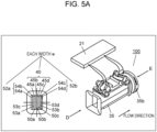
- Fig. 5A illustrates a flow path configuration diagram of ultrasonic flowmeter 100 using flow path body 35 to which a flow path is added to measure a larger gas flow rate in the conventional ultrasonic flowmeter according to PTL 1.
- An example of a fluid flow path is illustrated in which sub flow path 52a having two flow paths and sub flow path 52b having two sub flow paths are added to measurement flow path 40 having four flow paths, thus having a total of eight flow paths.
- Fig. 5B is a comparison diagram between outlet portion 35b which is a view taken along arrow E of ultrasonic flowmeter 100 in which the outer diameter of outlet portion 35b is set to ⁇ D2 illustrated in Fig. 5A and outlet portion 19b, illustrated in Figs. 1C and 2 , which is a view taken along arrow B of ultrasonic flowmeter 1 in which the outer diameter of outlet portion 19b is set to ⁇ D1 according to the first exemplary embodiment illustrated in Fig. 1A .
- fluid flow path 2 falls within circle F indicated by the dotted line
- fluid flow path 2 falls within circle G larger than circle F.
- Circle F and circle G correspond to the minimum diameter of flow path body 35 necessary for internally forming a fluid flow path. That is, as can be seen from Fig. 5B , ⁇ D1 ⁇ ⁇ D2 is set, and according to ultrasonic flowmeter 1 according to the first exemplary embodiment of the present disclosure, a compact configuration can be implemented by arranging sub flow path 22a and sub flow path 22b in minimum circle F including measurement flow path 4.
- added sub flow path 22a and added sub flow path 22b are arranged so as to be vertically and horizontally symmetrical with respect to widthwise center line X and heightwise center line Y of measurement flow path 4, including same plate thickness t of partition plates 20a, 20b, and 20c and sub partition plates 23a, 23b, 23c, and 23d.
- the pair of ultrasonic transducers including first ultrasonic transducer 6 and second ultrasonic transducer 7 are disposed upstream and downstream of an upper portion of fluid flow path 2.
- the ultrasonic flowmeter computes the flow velocity or flow rate of a measurement target fluid based on the propagation time from when the ultrasonic signal transmitted from one of the pair of ultrasonic transducers propagates through the measurement target fluid to when the ultrasonic signal is received by the other ultrasonic transducer. Accordingly, since an ultrasonic signal propagates only to the measurement flow path, the flow velocity or flow rate of a measurement target fluid passing through added sub flow path 22a and added sub flow path 22b is not directly measured.
- the flow rate of a measurement target fluid passing through measurement flow path 4 is calculated from the measurement result obtained in measurement flow path 4 that directly measures the passing measurement target fluid.
- the flow rate can be calculated by multiplying the flow path cross-sectional area (the sum of the flow path cross-sectional areas of measurement flow path 4, sub flow path 22a, and sub flow path 22b) of fluid flow path 2 by the flow velocity of the measurement target fluid obtained in measurement flow path 4.
- the ratios between the flow rate of measurement flow path 4 and the flow rates of sub flow path 22a and sub flow path 22b may be obtained in advance.
- the flow rates of sub flow path 22a and sub flow path 22b may be calculated from the flow rate of measurement flow path 4 and added together.
- the flow velocities of measurement flow path 4, sub flow path 22a, and sub flow path 22b are preferably the same even when the flow rate changes.
- sub flow path 22a and sub flow path 22b are vertically and horizontally symmetrical with respect to measurement flow path 4, a more uniform flow of the passing measurement target fluid can be implemented, and highly accurate measurement can be implemented.
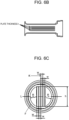
- Figs. 6A to 6C illustrate ultrasonic flowmeter 200 as an example of the above case.
- Fig. 6A is a flow path configuration diagram in a case in which a large flow rate can be measured by the conventional ultrasonic flowmeter.
- Fig. 6B is a cross sectional view taken along line 6B-6B of Fig. 6A .
- Fig. 6C is a view taken in the direction of arrow J in Fig. 6A .
- sub flow path 37a and sub flow path 37b are arranged on the left and right of measurement flow path 60 so as to be vertically and horizontally symmetrical with respect to widthwise center line X and heightwise center line Y.
- the flow path cross-sectional shapes of sub flow path 37a and sub flow path 37b are substantially semicircular unlike the rectangles of divided flow paths 65a, 65b, 65c, and 65d of measurement flow path 60, and the flow path cross-sectional areas of sub flow path 37a and sub flow path 37b are about 2.6 times larger than those of divided flow paths 65a to 65d of measurement flow path 60.
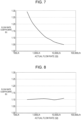
- Fig. 7 is a graph illustrating the flow rate measurement result obtained by ultrasonic flowmeter 200 illustrated in Figs. 6A to 6C in the form of actual flow rates and flow rate coefficients.
- measurement flow rate Qm is calculated as the total flow rate by multiplying the sum of the flow path cross-sectional areas of measurement flow path 60, sub flow path 37a, and sub flow path 37b by the flow velocity obtained in measurement flow path 60.
- Flow rate coefficient k is ideally 1 with respect to actual flow rate Qt on the horizontal axis.
- the flow rate coefficient indicates that actual flow rate Qt of the passing measurement target fluid coincides with the flow rate of the entire measurement target fluid, including sub flow path 37a and sub flow path 37b, which is calculated from the flow rate measured by measurement flow path 60. Therefore, it is ideal that flow rate coefficient k on the vertical axis changes in the vicinity of the value 1 with respect to actual flow rate Qt on the horizontal axis. This indicates that the measurement accuracy is high.
- the result illustrated in Fig. 7 shows a transition in which flow rate coefficient k shows a value larger than 1 at the time of a small flow rate, and flow rate coefficient k gradually approaches 1 at the time of a large flow rate.
- the fluid does not flow to the measurement flow path 60 side having a large flow path resistance at the time of a small flow rate but easily flows to the sub flow path 37a or sub flow path 37b side having a small flow path resistance, and the flow does not become uniform, resulting in the large velocity distribution of the measurement target fluid.
- the measurement target fluid does not sufficiently flow only by the flow path cross-sectional area of sub flow path 37a or sub flow path 37b, and hence flows also to the measurement flow path 60 side and gradually changes to a uniform flow.
- sub flow path 37a and sub flow path 37b added in this way are arranged vertically and horizontally symmetrically with respect to measurement flow path 60, the measurement accuracy may not be preferable. It is important to make the flow velocity distribution of the measurement target fluid uniform as much as possible from the small flow rate region to the large flow rate region.
- FIG. 8 illustrates the flow rate measurement result obtained by ultrasonic flowmeter 1 according to the first exemplary embodiment of the present disclosure illustrated in Figs. 1A to 1E and 2 .
- flow rate coefficient k changes in the vicinity of 1.10 in the flow rate region from the small flow rate region to the large flow rate region, there is almost no change in flow rate coefficient as illustrated in Fig. 7 , and the characteristic of the flow rate coefficient is flat and the measurement accuracy is high.
- an ultrasonic flowmeter that can implement highly accurate measurement while having a compact outer shape when measuring a measurement target fluid of a large flow rate.
- the flow path height of added flow path 24b of sub flow path 22a and added flow path 24c of sub flow path 22b is selected as h1 and the flow path height of added flow path 24a of sub flow path 22a and added flow path 24d of sub flow path 22b is selected as h2 so as to fall within circle F.
- the flow path width is set to width w, even if the flow path height is changed, highly accurate measurement can be performed.
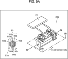
- Figs. 9A to 9C are configuration diagrams of ultrasonic flowmeter 300 according to the first modification.
- Fig. 9B is a cross sectional view taken along line 9B-9B of Fig. 9A .
- Fig. 9C is a view taken in the direction of arrow N in Fig. 9A .
- Measurement flow path 80 includes divided flow paths 85a, 85b, and 85c having a rectangular cross-sectional shape with width w and height h with partition plate 90a and partition plate 90b interposed between the divided flow paths.
- Sub flow path 92a and sub flow path 92b are added to measurement flow path 80 with sub partition plate 93a and sub partition plate 93b interposed, respectively, and are configured to have a rectangular cross-sectional shape with width w and height h1.
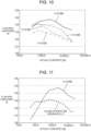
- Fig. 10 shows the flow rate measurement results obtained when flow path height h1 of sub flow path 92a and sub flow path 92b is changed.
- Fig. 10 is a graph illustrating flow rate coefficients with respect to the actual flow rates when flow path height h1 is set to 0.68h, 0.66h, 0.58h, and 0.50h.
- the flow path widths of divided flow paths 85a, 85b, and 85c, sub flow path 92a, and sub flow path 92b of measurement flow path 80 are set to width w, there is no large difference in the results even when the flow path heights are changed to four different heights, and the measurement can be stably performed with high accuracy. Accordingly, when there is a restriction on the external size of the ultrasonic flowmeter, since the flow path height can be arbitrarily changed while the flow path widths are aligned with width w, flexible design can be performed.
- the graph shown in Fig. 10 illustrates flow rate coefficient k when actual flow rate Qt falls within the range of 360 L/h to 25,000 L/h in ultrasonic flowmeter 300 according to the first modification.
- the solid line of the graph shown in Fig. 11 indicates flow rate coefficient k when the range of actual flow rate Qt is from 50 L/h to 25,000 L/h (inclusive) on the smaller flow rate side and flow path height h1 is 0.68 h.
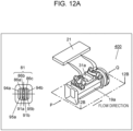
- Figs. 12A to 12C are configuration diagrams of ultrasonic flowmeter 400 according to the second modification.
- a difference from the shape of ultrasonic flowmeter 300 illustrated in Figs. 9A to 9C is that the shapes of sub flow paths 94a, 94b of ultrasonic flowmeter 400 are not rectangular but trapezoidal.
- the flow path widths (the interval between parallel sides of the trapezoid) of sub flow paths 94a, 94b is set to same width w as the flow path widths of divided flow paths 86a, 86b, and 86c of measurement flow path 81
- the flow path heights are set such that the long side is set to same height h as the flow path heights of divided flow paths 86a, 86b, and 86c and the short side is set to height h1 shorter than height h
- the sides corresponding to the legs of the trapezoid are formed obliquely along the circle including divided flow paths 86a, 86b, and 86c.
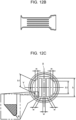
- the flow path cross-sectional areas of sub flow paths 94a, 94b according to the present modification can be made larger than those of the rectangular sub flow paths shown in Figs. 9A to 9C .
- the total flow path cross-sectional area in ultrasonic flowmeter 400 is increased by the areas of the four portions having the substantially triangular shapes, each indicated by the hatched lines in the enlarged view of Fig. 12C , each corresponding to one of the upper and lower end portions of sub flow paths 94a, 94b.
- flow path body 19 partition plates 20a, 20b, and sub partition plates 23a, 23b shown in Figs. 3A to 3C are integrally molded using the same material (for example, a resin) in ultrasonic flowmeter 400 shown in Figs. 12A to 12C .
- Ultrasonic flowmeter 400 may be integrally molded using the same material including ultrasonic transducer fixing body 31 illustrated in Fig. 4 .
- the added corners having the substantially triangular shape indicated by the hatching each have an appropriate substantially R shape.
- the mold release resistance can be reduced.
- the fluctuation range of flow rate coefficient k is suppressed (approximately 4% to approximately 1%) particularly on the small flow rate side where actual flow rate Qt is 50 L/h to 1,000 L/h (inclusive). That is, the measurement accuracy is improved.
- ultrasonic flowmeter 400 shown in Figs. 12A to 12C is integrally formed, including ultrasonic transducer fixing body 31a, by resin molding using the same material.
- the thickness of the resin becomes thick at the portion where flow path body 19a and ultrasonic transducer fixing body 31a are joined to each other.
- the substantially triangular flow path cross-section increasing portion is provided on the upper side of each of sub flow paths 94a, 94b, the thickness of the resin becomes more uniform, so that it can be expected to implement resin molding with higher dimensional accuracy.
- each sub flow path is formed into a rectangular cross-section by arbitrarily changing the flow path height upon aligning the flow path widths to width w.
- sub flow paths 94a, 94b are arranged symmetrically with respect to measurement flow path 81, which is a main flow path, while the cross-sectional shapes of sub flow paths 94a, 94b each are formed into a trapezoidal cross-section upon aligning the flow path widths of sub flow paths 94a, 94b to width w of divided flow paths 86a to 86c of measurement flow path 81 and the flow path height directions are made parallel within the range of predetermined values of the heights of divided flow paths 86a to 86c of measurement flow path 81.
- This allows flexible design for implementing a uniform flow.
- the flow path width of each flow path of each sub flow path added to the measurement flow path including the pair of ultrasonic transducers that can transmit and receive ultrasonic signals in a case in which a measurement target fluid with a larger flow rate is measured is set to be equal to the flow path width of each flow path of the measurement flow path.
Landscapes
- Physics & Mathematics (AREA)
- Fluid Mechanics (AREA)
- General Physics & Mathematics (AREA)
- Electromagnetism (AREA)
- Measuring Volume Flow (AREA)
Applications Claiming Priority (2)
| Application Number | Priority Date | Filing Date | Title |
|---|---|---|---|
| JP2019208656 | 2019-11-19 | ||
| PCT/JP2020/041835 WO2021100539A1 (ja) | 2019-11-19 | 2020-11-10 | 超音波流量計 |
Publications (4)
| Publication Number | Publication Date |
|---|---|
| EP4063802A1 EP4063802A1 (en) | 2022-09-28 |
| EP4063802A4 EP4063802A4 (en) | 2022-12-14 |
| EP4063802C0 EP4063802C0 (en) | 2024-09-25 |
| EP4063802B1 true EP4063802B1 (en) | 2024-09-25 |
Family
ID=75981254
Family Applications (1)
| Application Number | Title | Priority Date | Filing Date |
|---|---|---|---|
| EP20888902.2A Active EP4063802B1 (en) | 2019-11-19 | 2020-11-10 | Ultrasonic flowmeter |
Country Status (7)
| Country | Link |
|---|---|
| US (1) | US12123759B2 (pl) |
| EP (1) | EP4063802B1 (pl) |
| JP (2) | JPWO2021100539A1 (pl) |
| CN (1) | CN114585884A (pl) |
| ES (1) | ES2991333T3 (pl) |
| PL (1) | PL4063802T3 (pl) |
| WO (1) | WO2021100539A1 (pl) |
Families Citing this family (1)
| Publication number | Priority date | Publication date | Assignee | Title |
|---|---|---|---|---|
| CN120615161A (zh) * | 2023-01-31 | 2025-09-09 | 桑名金属工业株式会社 | 层流元件、流量传感器和质量流量控制器 |
Family Cites Families (21)
| Publication number | Priority date | Publication date | Assignee | Title |
|---|---|---|---|---|
| DE4118809C2 (de) * | 1991-06-07 | 1994-12-22 | Wagner Louise | Vorrichtung zur Messung kleiner Flüssigkeits- und Partikelströme |
| JP3193774B2 (ja) * | 1991-06-07 | 2001-07-30 | シューベルト・ウント・ザルツァー・コントロール・システムズ・ゲーエムベーハー | 液体及び粒子の微小流速流を測定する装置 |
| US6026693A (en) * | 1997-06-04 | 2000-02-22 | Baumoel; Douglas S. | Pipe spool section having square or rectangular cross-section for clamp on transducer and method for flow measurement |
| JP2003185477A (ja) * | 2001-12-21 | 2003-07-03 | Yazaki Corp | 流量計 |
| JP3935069B2 (ja) * | 2002-12-27 | 2007-06-20 | 東京瓦斯株式会社 | 流量計測装置 |
| KR100694937B1 (ko) | 2003-02-24 | 2007-03-14 | 마츠시타 덴끼 산교 가부시키가이샤 | 초음파식 유체 계측 장치 |
| JP2004279224A (ja) | 2003-03-17 | 2004-10-07 | Matsushita Electric Ind Co Ltd | 超音波流量計測装置 |
| JP4186645B2 (ja) * | 2003-02-24 | 2008-11-26 | 松下電器産業株式会社 | 超音波流量計測装置 |
| JP2012132801A (ja) * | 2010-12-22 | 2012-07-12 | Panasonic Corp | 超音波流量計 |
| JP2012247299A (ja) * | 2011-05-27 | 2012-12-13 | Panasonic Corp | 超音波式流量計測ユニットおよびこれを用いたガス流量計 |
| JP5974307B2 (ja) * | 2011-07-13 | 2016-08-23 | パナソニックIpマネジメント株式会社 | 超音波流量計 |
| JP2013024646A (ja) * | 2011-07-19 | 2013-02-04 | Hitachi-Ge Nuclear Energy Ltd | 超音波流量計及びこれを用いた流量計測方法 |
| JPWO2013051272A1 (ja) * | 2011-10-06 | 2015-03-30 | パナソニックIpマネジメント株式会社 | 流量計測装置の設定方法 |
| KR101361470B1 (ko) * | 2012-03-02 | 2014-02-11 | (주)씨엠엔텍 | 초음파 유량계 및 열량계 |
| JP6229143B2 (ja) * | 2013-04-23 | 2017-11-15 | パナソニックIpマネジメント株式会社 | 流量計測装置 |
| JP6229144B2 (ja) * | 2013-04-23 | 2017-11-15 | パナソニックIpマネジメント株式会社 | 流量計測装置 |
| US9304024B2 (en) * | 2014-01-13 | 2016-04-05 | Cameron International Corporation | Acoustic flow measurement device including a plurality of chordal planes each having a plurality of axial velocity measurements using transducer pairs |
| CN107218981A (zh) * | 2017-05-16 | 2017-09-29 | 湖北锐意自控系统有限公司 | 一种基于超声波旁流原理的气体流量测量装置及方法 |
| KR101833543B1 (ko) * | 2017-09-08 | 2018-03-02 | 한국환경공단 | 저탄소에 부합하는 비만관 하수 유량 측정 장치 |
| CA3090082C (en) * | 2018-02-01 | 2024-07-02 | Reliance Worldwide Corp | SENSOR BRACKET |
| JP7021832B2 (ja) * | 2018-05-09 | 2022-02-17 | アズビル金門株式会社 | 流量測定装置 |
-
2020
- 2020-11-10 ES ES20888902T patent/ES2991333T3/es active Active
- 2020-11-10 JP JP2021558308A patent/JPWO2021100539A1/ja active Pending
- 2020-11-10 US US17/641,248 patent/US12123759B2/en active Active
- 2020-11-10 WO PCT/JP2020/041835 patent/WO2021100539A1/ja not_active Ceased
- 2020-11-10 EP EP20888902.2A patent/EP4063802B1/en active Active
- 2020-11-10 CN CN202080072713.2A patent/CN114585884A/zh active Pending
- 2020-11-10 PL PL20888902.2T patent/PL4063802T3/pl unknown
-
2024
- 2024-04-08 JP JP2024062034A patent/JP7660328B2/ja active Active
Also Published As
| Publication number | Publication date |
|---|---|
| CN114585884A (zh) | 2022-06-03 |
| US20220333965A1 (en) | 2022-10-20 |
| PL4063802T3 (pl) | 2025-03-03 |
| JPWO2021100539A1 (pl) | 2021-05-27 |
| US12123759B2 (en) | 2024-10-22 |
| WO2021100539A1 (ja) | 2021-05-27 |
| EP4063802C0 (en) | 2024-09-25 |
| EP4063802A1 (en) | 2022-09-28 |
| JP7660328B2 (ja) | 2025-04-11 |
| JP2024088742A (ja) | 2024-07-02 |
| EP4063802A4 (en) | 2022-12-14 |
| ES2991333T3 (es) | 2024-12-03 |
Similar Documents
| Publication | Publication Date | Title |
|---|---|---|
| KR100694937B1 (ko) | 초음파식 유체 계측 장치 | |
| US6748811B1 (en) | Ultrasonic flowmeter | |
| CN103459988B (zh) | 超声波流量计测装置 | |
| EP3835733B1 (en) | Ultrasonic flow meter | |
| JP2010164558A (ja) | 流体の流れ計測装置 | |
| CN108593026B (zh) | 一种基于超声波原理的流道结构及气体流量计量表 | |
| JP5974307B2 (ja) | 超音波流量計 | |
| JP2012247299A (ja) | 超音波式流量計測ユニットおよびこれを用いたガス流量計 | |
| EP4063802B1 (en) | Ultrasonic flowmeter | |
| US11802782B2 (en) | Ultrasonic flowmeter with a flow path inner wall surface with a draft of a mold for integral molding | |
| JP2014077679A (ja) | 流量計 | |
| JP7688519B2 (ja) | ガスメータ | |
| CN112543861A (zh) | 超声波流量计 | |
| JP2014077750A (ja) | 超音波メータ | |
| JP6889238B1 (ja) | 超音波式ガスメーター | |
| JP6306434B2 (ja) | 超音波流量計 | |
| JPWO2021100539A5 (pl) | ||
| JP7285453B2 (ja) | 超音波流量計 | |
| US11761804B2 (en) | Ultrasonic flowmeter having a partition plate dividing the flow path into a measurement flow path and a non-measurement flow path | |
| JP2013057613A (ja) | 超音波流量計 | |
| CN217403534U (zh) | 测量流道及燃气表 | |
| JP2003307445A (ja) | 超音波流量計測装置 | |
| JP2021117018A (ja) | 超音波流量計 | |
| JP2019196968A (ja) | 超音波流量計 | |
| JP2019191040A (ja) | 超音波流量計 |
Legal Events
| Date | Code | Title | Description |
|---|---|---|---|
| STAA | Information on the status of an ep patent application or granted ep patent |
Free format text: STATUS: THE INTERNATIONAL PUBLICATION HAS BEEN MADE |
|
| PUAI | Public reference made under article 153(3) epc to a published international application that has entered the european phase |
Free format text: ORIGINAL CODE: 0009012 |
|
| STAA | Information on the status of an ep patent application or granted ep patent |
Free format text: STATUS: REQUEST FOR EXAMINATION WAS MADE |
|
| 17P | Request for examination filed |
Effective date: 20220318 |
|
| AK | Designated contracting states |
Kind code of ref document: A1 Designated state(s): AL AT BE BG CH CY CZ DE DK EE ES FI FR GB GR HR HU IE IS IT LI LT LU LV MC MK MT NL NO PL PT RO RS SE SI SK SM TR |
|
| A4 | Supplementary search report drawn up and despatched |
Effective date: 20221115 |
|
| RIC1 | Information provided on ipc code assigned before grant |
Ipc: G01F 1/667 20220101ALI20221109BHEP Ipc: G01F 1/66 20220101AFI20221109BHEP |
|
| DAV | Request for validation of the european patent (deleted) | ||
| DAX | Request for extension of the european patent (deleted) | ||
| REG | Reference to a national code |
Ref country code: DE Ref legal event code: R079 Free format text: PREVIOUS MAIN CLASS: G01F0001660000 Ref country code: DE Ref legal event code: R079 Ref document number: 602020038495 Country of ref document: DE Free format text: PREVIOUS MAIN CLASS: G01F0001660000 Ipc: G01F0015000000 |
|
| GRAP | Despatch of communication of intention to grant a patent |
Free format text: ORIGINAL CODE: EPIDOSNIGR1 |
|
| STAA | Information on the status of an ep patent application or granted ep patent |
Free format text: STATUS: GRANT OF PATENT IS INTENDED |
|
| RIC1 | Information provided on ipc code assigned before grant |
Ipc: G01F 1/667 20220101ALI20240327BHEP Ipc: G01F 1/66 20060101ALI20240327BHEP Ipc: G01F 15/00 20060101AFI20240327BHEP |
|
| INTG | Intention to grant announced |
Effective date: 20240430 |
|
| GRAS | Grant fee paid |
Free format text: ORIGINAL CODE: EPIDOSNIGR3 |
|
| GRAA | (expected) grant |
Free format text: ORIGINAL CODE: 0009210 |
|
| STAA | Information on the status of an ep patent application or granted ep patent |
Free format text: STATUS: THE PATENT HAS BEEN GRANTED |
|
| AK | Designated contracting states |
Kind code of ref document: B1 Designated state(s): AL AT BE BG CH CY CZ DE DK EE ES FI FR GB GR HR HU IE IS IT LI LT LU LV MC MK MT NL NO PL PT RO RS SE SI SK SM TR |
|
| REG | Reference to a national code |
Ref country code: GB Ref legal event code: FG4D |
|
| REG | Reference to a national code |
Ref country code: CH Ref legal event code: EP |
|
| REG | Reference to a national code |
Ref country code: DE Ref legal event code: R096 Ref document number: 602020038495 Country of ref document: DE |
|
| REG | Reference to a national code |
Ref country code: IE Ref legal event code: FG4D |
|
| U01 | Request for unitary effect filed |
Effective date: 20241018 |
|
| REG | Reference to a national code |
Ref country code: ES Ref legal event code: FG2A Ref document number: 2991333 Country of ref document: ES Kind code of ref document: T3 Effective date: 20241203 |
|
| U07 | Unitary effect registered |
Designated state(s): AT BE BG DE DK EE FI FR IT LT LU LV MT NL PT RO SE SI Effective date: 20241104 |
|
| U20 | Renewal fee for the european patent with unitary effect paid |
Year of fee payment: 5 Effective date: 20241126 |
|
| PG25 | Lapsed in a contracting state [announced via postgrant information from national office to epo] |
Ref country code: NO Free format text: LAPSE BECAUSE OF FAILURE TO SUBMIT A TRANSLATION OF THE DESCRIPTION OR TO PAY THE FEE WITHIN THE PRESCRIBED TIME-LIMIT Effective date: 20241225 |
|
| PG25 | Lapsed in a contracting state [announced via postgrant information from national office to epo] |
Ref country code: GR Free format text: LAPSE BECAUSE OF FAILURE TO SUBMIT A TRANSLATION OF THE DESCRIPTION OR TO PAY THE FEE WITHIN THE PRESCRIBED TIME-LIMIT Effective date: 20241226 |
|
| PGFP | Annual fee paid to national office [announced via postgrant information from national office to epo] |
Ref country code: GB Payment date: 20241120 Year of fee payment: 5 |
|
| PG25 | Lapsed in a contracting state [announced via postgrant information from national office to epo] |
Ref country code: RS Free format text: LAPSE BECAUSE OF FAILURE TO SUBMIT A TRANSLATION OF THE DESCRIPTION OR TO PAY THE FEE WITHIN THE PRESCRIBED TIME-LIMIT Effective date: 20241225 |
|
| PGFP | Annual fee paid to national office [announced via postgrant information from national office to epo] |
Ref country code: ES Payment date: 20241230 Year of fee payment: 5 |
|
| PG25 | Lapsed in a contracting state [announced via postgrant information from national office to epo] |
Ref country code: RS Free format text: LAPSE BECAUSE OF FAILURE TO SUBMIT A TRANSLATION OF THE DESCRIPTION OR TO PAY THE FEE WITHIN THE PRESCRIBED TIME-LIMIT Effective date: 20241225 Ref country code: NO Free format text: LAPSE BECAUSE OF FAILURE TO SUBMIT A TRANSLATION OF THE DESCRIPTION OR TO PAY THE FEE WITHIN THE PRESCRIBED TIME-LIMIT Effective date: 20241225 Ref country code: GR Free format text: LAPSE BECAUSE OF FAILURE TO SUBMIT A TRANSLATION OF THE DESCRIPTION OR TO PAY THE FEE WITHIN THE PRESCRIBED TIME-LIMIT Effective date: 20241226 |
|
| PG25 | Lapsed in a contracting state [announced via postgrant information from national office to epo] |
Ref country code: IS Free format text: LAPSE BECAUSE OF FAILURE TO SUBMIT A TRANSLATION OF THE DESCRIPTION OR TO PAY THE FEE WITHIN THE PRESCRIBED TIME-LIMIT Effective date: 20250125 |
|
| PG25 | Lapsed in a contracting state [announced via postgrant information from national office to epo] |
Ref country code: SM Free format text: LAPSE BECAUSE OF FAILURE TO SUBMIT A TRANSLATION OF THE DESCRIPTION OR TO PAY THE FEE WITHIN THE PRESCRIBED TIME-LIMIT Effective date: 20240925 |
|
| PG25 | Lapsed in a contracting state [announced via postgrant information from national office to epo] |
Ref country code: CZ Free format text: LAPSE BECAUSE OF FAILURE TO SUBMIT A TRANSLATION OF THE DESCRIPTION OR TO PAY THE FEE WITHIN THE PRESCRIBED TIME-LIMIT Effective date: 20240925 |
|
| PGFP | Annual fee paid to national office [announced via postgrant information from national office to epo] |
Ref country code: PL Payment date: 20241114 Year of fee payment: 5 |
|
| PG25 | Lapsed in a contracting state [announced via postgrant information from national office to epo] |
Ref country code: SK Free format text: LAPSE BECAUSE OF FAILURE TO SUBMIT A TRANSLATION OF THE DESCRIPTION OR TO PAY THE FEE WITHIN THE PRESCRIBED TIME-LIMIT Effective date: 20240925 |
|
| REG | Reference to a national code |
Ref country code: CH Ref legal event code: PL |
|
| PG25 | Lapsed in a contracting state [announced via postgrant information from national office to epo] |
Ref country code: MC Free format text: LAPSE BECAUSE OF FAILURE TO SUBMIT A TRANSLATION OF THE DESCRIPTION OR TO PAY THE FEE WITHIN THE PRESCRIBED TIME-LIMIT Effective date: 20240925 |
|
| REG | Reference to a national code |
Ref country code: CH Ref legal event code: PL |
|
| PG25 | Lapsed in a contracting state [announced via postgrant information from national office to epo] |
Ref country code: CH Free format text: LAPSE BECAUSE OF NON-PAYMENT OF DUE FEES Effective date: 20241130 |
|
| PLBE | No opposition filed within time limit |
Free format text: ORIGINAL CODE: 0009261 |
|
| STAA | Information on the status of an ep patent application or granted ep patent |
Free format text: STATUS: NO OPPOSITION FILED WITHIN TIME LIMIT |
|
| 26N | No opposition filed |
Effective date: 20250626 |
|
| PG25 | Lapsed in a contracting state [announced via postgrant information from national office to epo] |
Ref country code: IE Free format text: LAPSE BECAUSE OF NON-PAYMENT OF DUE FEES Effective date: 20241110 |