EP4063751B1 - Verfahren zur steuerung eines lüftungs-, heizungs-, klimatisierungs- und/oder luftreinigungssystems - Google Patents
Verfahren zur steuerung eines lüftungs-, heizungs-, klimatisierungs- und/oder luftreinigungssystems Download PDFInfo
- Publication number
- EP4063751B1 EP4063751B1 EP22163315.9A EP22163315A EP4063751B1 EP 4063751 B1 EP4063751 B1 EP 4063751B1 EP 22163315 A EP22163315 A EP 22163315A EP 4063751 B1 EP4063751 B1 EP 4063751B1
- Authority
- EP
- European Patent Office
- Prior art keywords
- air
- zone
- flow rate
- polluted
- fresh air
- Prior art date
- Legal status (The legal status is an assumption and is not a legal conclusion. Google has not performed a legal analysis and makes no representation as to the accuracy of the status listed.)
- Active
Links
Images


Classifications
-
- F—MECHANICAL ENGINEERING; LIGHTING; HEATING; WEAPONS; BLASTING
- F24—HEATING; RANGES; VENTILATING
- F24F—AIR-CONDITIONING; AIR-HUMIDIFICATION; VENTILATION; USE OF AIR CURRENTS FOR SCREENING
- F24F3/00—Air-conditioning systems in which conditioned primary air is supplied from one or more central stations to distributing units in the rooms or spaces where it may receive secondary treatment; Apparatus specially designed for such systems
- F24F3/044—Systems in which all treatment is given in the central station, i.e. all-air systems
-
- F—MECHANICAL ENGINEERING; LIGHTING; HEATING; WEAPONS; BLASTING
- F24—HEATING; RANGES; VENTILATING
- F24F—AIR-CONDITIONING; AIR-HUMIDIFICATION; VENTILATION; USE OF AIR CURRENTS FOR SCREENING
- F24F11/00—Control or safety arrangements
- F24F11/0001—Control or safety arrangements for ventilation
-
- F—MECHANICAL ENGINEERING; LIGHTING; HEATING; WEAPONS; BLASTING
- F24—HEATING; RANGES; VENTILATING
- F24F—AIR-CONDITIONING; AIR-HUMIDIFICATION; VENTILATION; USE OF AIR CURRENTS FOR SCREENING
- F24F13/00—Details common to, or for air-conditioning, air-humidification, ventilation or use of air currents for screening
- F24F13/02—Ducting arrangements
- F24F13/0236—Ducting arrangements with ducts including air distributors, e.g. air collecting boxes with at least three openings
-
- F—MECHANICAL ENGINEERING; LIGHTING; HEATING; WEAPONS; BLASTING
- F24—HEATING; RANGES; VENTILATING
- F24F—AIR-CONDITIONING; AIR-HUMIDIFICATION; VENTILATION; USE OF AIR CURRENTS FOR SCREENING
- F24F13/00—Details common to, or for air-conditioning, air-humidification, ventilation or use of air currents for screening
- F24F13/08—Air-flow control members, e.g. louvres, grilles, flaps or guide plates
- F24F13/10—Air-flow control members, e.g. louvres, grilles, flaps or guide plates movable, e.g. dampers
-
- F—MECHANICAL ENGINEERING; LIGHTING; HEATING; WEAPONS; BLASTING
- F24—HEATING; RANGES; VENTILATING
- F24F—AIR-CONDITIONING; AIR-HUMIDIFICATION; VENTILATION; USE OF AIR CURRENTS FOR SCREENING
- F24F3/00—Air-conditioning systems in which conditioned primary air is supplied from one or more central stations to distributing units in the rooms or spaces where it may receive secondary treatment; Apparatus specially designed for such systems
- F24F3/12—Air-conditioning systems in which conditioned primary air is supplied from one or more central stations to distributing units in the rooms or spaces where it may receive secondary treatment; Apparatus specially designed for such systems characterised by the treatment of the air otherwise than by heating and cooling
- F24F3/16—Air-conditioning systems in which conditioned primary air is supplied from one or more central stations to distributing units in the rooms or spaces where it may receive secondary treatment; Apparatus specially designed for such systems characterised by the treatment of the air otherwise than by heating and cooling by purification, e.g. by filtering; by sterilisation; by ozonisation
-
- F—MECHANICAL ENGINEERING; LIGHTING; HEATING; WEAPONS; BLASTING
- F24—HEATING; RANGES; VENTILATING
- F24F—AIR-CONDITIONING; AIR-HUMIDIFICATION; VENTILATION; USE OF AIR CURRENTS FOR SCREENING
- F24F7/00—Ventilation
- F24F7/04—Ventilation with ducting systems, e.g. by double walls; with natural circulation
- F24F7/06—Ventilation with ducting systems, e.g. by double walls; with natural circulation with forced air circulation, e.g. by fan positioning of a ventilator in or against a conduit
-
- F—MECHANICAL ENGINEERING; LIGHTING; HEATING; WEAPONS; BLASTING
- F24—HEATING; RANGES; VENTILATING
- F24F—AIR-CONDITIONING; AIR-HUMIDIFICATION; VENTILATION; USE OF AIR CURRENTS FOR SCREENING
- F24F2110/00—Control inputs relating to air properties
- F24F2110/50—Air quality properties
- F24F2110/65—Concentration of specific substances or contaminants
-
- F—MECHANICAL ENGINEERING; LIGHTING; HEATING; WEAPONS; BLASTING
- F24—HEATING; RANGES; VENTILATING
- F24F—AIR-CONDITIONING; AIR-HUMIDIFICATION; VENTILATION; USE OF AIR CURRENTS FOR SCREENING
- F24F2110/00—Control inputs relating to air properties
- F24F2110/50—Air quality properties
- F24F2110/65—Concentration of specific substances or contaminants
- F24F2110/66—Volatile organic compounds [VOC]
-
- F—MECHANICAL ENGINEERING; LIGHTING; HEATING; WEAPONS; BLASTING
- F24—HEATING; RANGES; VENTILATING
- F24F—AIR-CONDITIONING; AIR-HUMIDIFICATION; VENTILATION; USE OF AIR CURRENTS FOR SCREENING
- F24F2120/00—Control inputs relating to users or occupants
- F24F2120/10—Occupancy
-
- Y—GENERAL TAGGING OF NEW TECHNOLOGICAL DEVELOPMENTS; GENERAL TAGGING OF CROSS-SECTIONAL TECHNOLOGIES SPANNING OVER SEVERAL SECTIONS OF THE IPC; TECHNICAL SUBJECTS COVERED BY FORMER USPC CROSS-REFERENCE ART COLLECTIONS [XRACs] AND DIGESTS
- Y02—TECHNOLOGIES OR APPLICATIONS FOR MITIGATION OR ADAPTATION AGAINST CLIMATE CHANGE
- Y02B—CLIMATE CHANGE MITIGATION TECHNOLOGIES RELATED TO BUILDINGS, e.g. HOUSING, HOUSE APPLIANCES OR RELATED END-USER APPLICATIONS
- Y02B30/00—Energy efficient heating, ventilation or air conditioning [HVAC]
- Y02B30/70—Efficient control or regulation technologies, e.g. for control of refrigerant flow, motor or heating
Definitions
- the invention relates to a method for controlling a ventilation, heating, air conditioning and/or purification system for several zones of a room, in particular a room in the tertiary sector.
- a premises particularly a tertiary sector premises
- maintaining an optimal level of air quality is necessary to ensure a satisfactory level of comfort and health for the occupants of said premises.
- the level of air quality is often imposed by regulations for tertiary sector premises, such as the standard departmental health regulations (RSDT).
- RSDT standard departmental health regulations
- the RSDT sets limit values that certain indoor air pollutants in the premises must not exceed in order to guarantee the comfort and health of the occupants.
- WHO World Health Organization
- thresholds can be set at different levels. Those defined by the WHO are more ambitious than the limit values established in the RSDT.
- FR 3082288 A1 discloses a ventilation device for ventilating and heating or air conditioning the interior space of a building.
- EP 3767194 A1 discloses an air flow regulating organ.
- the aim of the invention is to propose a method which overcomes this drawback.
- the step of increasing the flow rate of recycled air comprises an activation of a device for regulating the flow rate of recycled air, called the second regulating device, arranged in the second air outlet, the second regulating device being movable between a position of complete closure of the second air outlet and a position of complete opening of the second air outlet.
- the second regulating device a device for regulating the flow rate of recycled air
- the second device for regulating said mouth associated with said at least one polluted zone moves so as to increase a section of the second air outlet of said mouth associated with said at least one polluted zone, and/or the second devices for regulating the zones unpolluted ones move so as to reduce a section of the respective second air outlets.
- the first device for regulating said at least one polluted zone moves so as to increase a section of the first air outlet of said outlet associated with said at least one polluted zone, and/or the first devices for regulating the unpolluted zones move so as to reduce a section of the respective first air outlets.
- the step of increasing the flow of fresh air by said first device for regulating the outlet associated with said at least one polluted zone lasts until the pollution ratio is lower than the unit value in the polluted zone.
- the increase in the flow of recycled air and/or the increase in the flow of fresh air is correlated with the value of the pollution ratio.
- a flow of fresh air entering the regulating member is kept constant.
- a flow of fresh air entering the regulating member is variable.
- an order of priority is established between the at least two constituents of the air, a value of the increase in the flow of fresh air and/or the flow of recycled air depending on said order of priority.
- the order of priority is established according to an absolute difference between the pollution ratio and the unit value for each constituent of the air, and/or a nature of each constituent of the air, and/or a detection of a human presence in the polluted zone.
- the second air outlet of each mouthpiece provides a flow of recycled air to the respective zone(s) of the room during defined time slots.
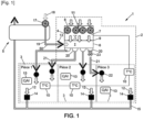
- a system 1 for ventilation, heating, air conditioning, and/or purification of a room 2 is represented on the Figure 1 .
- Room 2 contains several zones 3.
- Room 2 belongs to a building used, for example, in the tertiary economic sector.
- zones 3 are offices. From now on, we will call "exterior" an exterior of the building.
- room 2 is, for example, an individual or collective dwelling.
- system 1 is also suitable for delimited zones without fixed partitions either inside room 2 or inside a room in room 2, for example for an open workspace also called "open space" in English.
- the air in each of the 3 zones may be renewed for health and/or regulatory reasons.
- the air in each of the 3 zones may be brought up to temperature for comfort and/or regulatory reasons.
- the air in each of the 3 zones may be purified for health and/or regulatory reasons.
- the system 1 allows the zones 3 to each benefit from ventilation, heating and/or air conditioning.
- the system 1 may comprise a device 4 for thermally treating air flow and a ventilation device 5 which will be described later.
- the system 1 further comprises an air flow regulating member 6.
- the regulating member 6 will be described later with reference to figures 2 to 7 .
- the heat treatment device 4 and the ventilation device 5 are fluidically connected to the air flow regulating member 6.
- a fluid here air, can circulate between the ventilation device 5 and the heat treatment device 4 on the one hand, and the regulating member 6 on the other hand.
- the system 1 may further comprise an air flow purification treatment device 11.
- purification is meant, for example, that the air is totally or partially freed from impurities, such as microbes, viruses, bacteria, insects, microorganisms, particles, volatile or semi-volatile organic compounds, polluting gas molecules, inorganic compounds, etc.
- Air purification treatment is, for example, a physicochemical treatment of the air.
- Physicochemical treatment includes, for example, mechanical filtration, gravimetric filtration, adsorption, ionization and capture, electrostatic filtration, ozonization, plasma, photocatalysis, biofiltration, use of a disinfectant or radiation, use of activated carbon, etc.
- the air purification treatment corresponds solely to an internal mixing (or dilution) of the air from several zones 3, without application of physicochemical treatment.
- the internal mixing makes it possible to mix the air from one or more more polluted zone(s) with the air from one or more less polluted zone(s).
- air is obtained comprising a concentration of pollutants intermediate between a concentration of pollutants of the more polluted zone(s) and a concentration of pollutants of the less polluted zone(s).
- air purification treatment combines internal mixing and physicochemical treatment of air.
- the purification treatment device 11 is fluidically connected to the air flow regulating member 6.
- a fluid here air, can circulate between the purification treatment 11 and the regulating member 6.
- the purification treatment device 11 is an independent device from the heat treatment device 4. In some cases, the purification treatment device 11 and the heat treatment device 4 form a single device.
- the purification treatment device 11 and the heat treatment device 4 are integrated in the same box 7.
- the system 1 does not comprise a heat treatment device 4 and only the purification treatment device 11 is provided in the box 7.
- the purification treatment device 11 is located in a first box upstream of a second box housing the heat treatment device 4. In the following, only the example of the Figure 1 , in which the purification treatment device 11 and the thermal treatment device 4 are integrated in the same box 7.
- the box 7 advantageously has the shape of a rectangular parallelepiped.
- one of the faces of the box 7 is open so as to constitute a suction mouth 8.
- the suction mouth 8 is equipped with a suction means, capable of sucking in a flow of air from the room 2, called a recycled air flow.
- the suction means 8 comprises fans for sucking in the recycled air flow, as shown in the Figure 1 .
- the suction outlet 8 is arranged inside the room 2, so that the recycled air flow originates from one or more zones 3 of the room 2.
- the recycled air flow is made up of one or more air flows originating from one or more zones 3.
- the recycled air flow is made up solely of air flows originating from one or more zones 3 called “living rooms”.
- living room is meant any room not equipped with a water supply. In such cases, the suction means 8 is only arranged in the living rooms.
- the box 7 preferably comprises at least one heat exchanger (not shown) belonging to the heat treatment device 4.
- the heat exchanger may for example be an evaporator or a condenser.
- the heat exchanger is capable of modifying the temperature of the air flow sucked in by the suction mouth 8, so as to control a temperature of the recycled air flow.
- a thermal control system (not shown) is connected to the air heat treatment device 4.
- the thermal control system comprises at least one temperature sensor 10 installed in each zone 3.
- the at least one temperature sensor 10 makes it possible to measure the air temperature in each zone 3.
- the thermal control system further comprises an electronic control box (not shown) for the heat treatment device 4, and an electronic connection electronically connecting the control box and the temperature sensors 10 of each zone 3. This connection may be wired or not depending on the exemplary embodiments.
- the heat exchanger in the box 7 can adjust the temperature of the recycled air flow according to a set temperature of the air in each zone 3.
- set temperature is meant a desirable temperature of the air in each zone 3 making it possible to ensure comfort for at least one occupant of the zone 3.
- the set temperature can be established manually by the occupant of each zone 3. In certain cases, the set temperature can be established automatically, for example according to an outside temperature or a time slot. As will be detailed later, the system 1 is designed so that the ambient air temperature is adjustable for each of the zones 3, independently of the other zones 3.
- the purification treatment device 11 comprises for example at least one filter (not shown).
- the at least one filter is for example installed in the box 7 near the suction inlet 8.
- the at least one filter makes it possible to filter the recycled air flow so as to rid the recycled air flow of impurities.
- the purification treatment device 11 may comprise a space for mixing the air flows from different zones 3 and forming the recycled airflow.
- the purification treatment device 11 combines the filtration and mixing of the airflows forming the recycled airflow.
- the purification treatment device 11 can advantageously be connected to an air quality sensor system.
- the air quality sensor system comprises at least one sensor 13.
- at least one sensor 13 is installed in each zone 3 of the room 2. Such cases are encountered in particular when the zones 3 are completely separated from each other by walls or constitute enclosed spaces.
- the at least one sensor 13 is shared between several zones 3. Such cases are encountered in particular when the zones 3 are not separated from each other by walls, when the walls do not completely separate the zones 3 or when the zones 3 do not constitute enclosed spaces.
- certain zones 3 are devoid of sensors 13.
- inorganic compound(s) examples include carbon dioxide ( CO2 ), carbon monoxide (CO), ozone (Os), nitric oxide (NO), nitrogen dioxide ( NO2 ) and/or radon, among others.
- the volatile organic compound(s) are for example alcohols, aldehydes, ketones, hydrocarbons and/or terpenes, among others.
- the volatile organic compound(s) are for example benzene, formaldehyde, naphthalene, trichloroethylene, tetrachloroethylene, acid hydrocyanic acid, acetaldehyde, acrolein, ethylbenzene and/or toluene, among others.
- semi-volatile organic compound(s) examples include phthalates, polycyclic aromatic hydrocarbons, musks and/or pesticides, among others.
- microorganism we mean a living organism invisible to the naked eye, such as viruses or bacteria for example.
- the amount of water vapor in the polluted area at a given temperature determines a relative humidity in the polluted area.
- the relative humidity is defined as a ratio between a partial pressure of the water vapor contained in the air of each zone 3 at the given temperature on a saturated vapor pressure in said zone 3 at the given temperature.
- the relative humidity in the zones 3 is preferably in a range of values between 30% and 70%, more preferably between 40% and 60%. Above the upper values of said ranges of values, there is for example a risk of degradation of the room 2, in particular by proliferation of bacteria, or condensation and infiltration of water in the walls. Below the lower values of said ranges of values, there is for example a risk of loss of comfort, or even a health risk, for the occupants of room 2. The occupants may for example experience drying of the mucous membranes due to dry conditions in room 2. Thus, when the relative humidity in one of the zones 3 is outside said ranges of values, zone 3 is considered a polluted zone.
- the at least one sensor 13 is a presence sensor for determining human presence in the respective zone 3.
- the air quality sensor system further comprises an electronic control box (not shown) and an electronic connection electronically connecting the control box and the sensors 13 of each zone 3.
- the control box is provided with a support storage (not shown), such as a memory.
- the control box can also be equipped with a processor (not shown).
- the electronic connection can be wired or not depending on the embodiments.
- the purification treatment device 11 cannot operate. In some cases, when the purification treatment device 11 is in operation, the heat treatment device 4 cannot operate. In some cases, the heat treatment device 4 and the purification treatment device 11 may operate concomitantly. In some cases, the operation of the heat treatment device 4 is prioritized. Thus, when the heat treatment device 4 is activated, the purification treatment device 11 may be automatically stopped. In some cases, the operation of the purification treatment device 11 is prioritized. Thus, when the purification treatment device 11 is activated, the heat treatment device 4 may be automatically stopped.
- a face of the box 7 parallel to the suction mouth 8 is also open so as to constitute an outlet 9 through which the recycled air flow flows.
- the outlet 9 is fluidically connected to the air flow regulating member 6.
- the ventilation device 5 comprises a ventilation network capable of sucking in stale air flows 12 from the zones 3 of the room 2 to extract them from the room 2 to the outside.
- the ventilation network comprises a plurality of return vents 14 capable of sucking in the stale air flows 12.
- Each return vent 14 is arranged in one of the zones 3 of the room 2.
- Each return vent 14 is fluidically connected to the ventilation device 5 via a network of ducts 15, so as to be able to extract the stale air flows.
- wet rooms zones 3 known as "wet rooms”. Such cases are encountered, for example when room 2 is an individual or collective dwelling.
- a "wet room” means any room equipped with at least one water inlet. Wet rooms can be, for example, a kitchen, a bathroom, a shower room, toilets, etc. In such cases, the return vents 14 can only be placed in the wet rooms.
- the ventilation device 5 is furthermore capable of sucking in a flow of fresh air from outside to transmit it to the interior of the room 2 via the regulating member 6.
- the ventilation device 5 comprises a suction inlet equipped with a suction system 17, capable of sucking in a first flow of fresh air 18.
- the suction system 17 may comprise a fan and/or an air flow rate modulator in order to suck in the first flow of fresh air 18.
- This first flow of fresh air 18 comes from outside the building and is intended to be blown into the room 2.
- the ventilation device 5 may comprise at least one filter (not shown).
- the filter of the ventilation device 5 is for example arranged in the suction inlet.
- the filter is for example a gravimetric filter.
- a volume of fresh air in the first fresh air flow 18 may be fixed, in which case a fresh air flow rate is called a “fixed flow rate”.
- the volume of fresh air in the first fresh air flow 18 may instead be variable, in which case the fresh air flow rate is called a “variable flow rate”.
- the ventilation device 5 may comprise any type of machine capable of performing this function of sucking in fresh air from the outside and discharging stale air to the outside.
- so-called “single-flow” machines may be suitable.
- so-called “double-flow” machines may also be suitable.
- the ventilation device 5 also comprises a fresh air outlet 19 fluidically connected to the air flow regulating member 6 so as to convey all or part of the first fresh air flow 18 to the air flow regulating member 6.
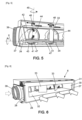
- the air flow regulating member 6 is installed in a false ceiling. Also, reference will be made to the vertical and horizontal directions subsequently to describe the relative locations of the elements composing the air flow regulating member 6 with reference to the figures 2 to 7 . A person skilled in the art will understand that these directions are relative to each other, and refer to the directions of space in a position of use of the air flow regulating member 6 in a false ceiling.
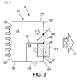
- the air flow regulating member 6 comprises a box 24 advantageously having the general shape of a rectangular parallelepiped.
- the front face 29 comprises a plurality of outlets 42 for recycled air flow, a plurality of outlets 43 for fresh air flow and a plurality of openings 20.
- the rear face 30 of the box 24 is covered with a rectangular plate 31 hollowed out in its center with a rectangle of smaller dimensions than the rectangular plate 31 hollowed out in its center.
- the recess is for example of the shape rectangular, as seen on the Figure 6
- the hollowed-out rectangular plate 31 forms, by its recess, an inlet 32 for the flow of air recycled from the heat treatment device 4 and/or the purification treatment device 11.
- This inlet 32 thus has a horizontal extent making it possible to distribute the flow of recycled air over the entire length of the box 24.
- a device for distributing the recycled air flow opposite the inlet 32 comprises at least two deflectors 33 in order to deflect the recycled air flow from the center of the box 24 towards the peripheral lateral parts. Thanks to these characteristics, the air flow regulating member 6 makes it possible to distribute a recycled air flow in a substantially homogeneous manner over the plurality of recycled air flow outlets 42. In certain cases, the recycled air flow to be distributed over the plurality of outlets 42 is constant. In other cases, the recycled air flow to be distributed over the plurality of outlets 42 is variable.
- the fluid connection between the outlet 9 of the box 7 and the air flow regulating member 6 is achieved by fixing the rear face 30 of the box 24 to the outlet 9.
- the regulating member 6 is fluidically connected to the heat treatment device 4 and/or to the air flow purification treatment device 11.
- the partition 34 has a general U shape, that is to say composed of a rectangular horizontal plate of which two opposite edges 37 and 38 are folded so as to form two plates inclined symmetrically with respect to a vertical plane.
- the two inclined plates are integral with the ceiling of the box 24.
- the hollowed-out rectangular vertical plate closes the external parts of the U and leaves open by its hollow only the interior of the U.
- the interior of the U thus forms the compartment 35 for supplying recycled air flow while the exterior of the U forms the compartment 36 for supplying fresh air flow, as described below in more detail.
- the lateral face 28 comprises a duct 39 forming a fresh air flow inlet.
- the fresh air flow inlet 39 can be fluidically connected to the fresh air outlet 19 of the ventilation device 5 by a network 50.
- the duct 39 allows the entry into the regulating member 6 of a fresh air flow, called the overall fresh air flow.
- the network 50 can comprise one or more control members (not shown) for the fresh air flow entering the regulating member 6.
- the overall fresh air flow is kept constant.
- the overall fresh air flow is variable.
- the overall fresh air flow can be variable, then constant, or vice versa.
- the inlet 39 is arranged on a plate removably fixed to the box by means of screws 400.
- the removable plate can be alternately arranged on one or other of the small lateral faces 27, 28, while the other small lateral face 28, 27 is equipped with another removable plate not having a conduit.
- the box 24 can be hermetically closed by the removable plate.
- an operator can choose the simplest configuration depending on the environment, in order to connect the regulating member 6 to the ventilation device 5 by the network 50 via the conduit 39.
- one of the inclined plates 37, 38 of the partition 34 being arranged opposite the duct 39 makes it possible, in operation, to deflect the fresh air into the fresh air flow supply compartment 36.
- Each of the mouthpieces 20 has, for example, a circular shape.
- the rectangular horizontal plate of the partition 34 delimits each of the mouths 20 into two portions, one upper 40 and the other lower 41.
- a section of the upper portion 40 represents for example approximately 3 ⁇ 4 of the total section of the mouth 20.
- a section of the lower portion 41 represents for example approximately 1 ⁇ 4 of the total section of the mouth 20.
- the upper portion 40 forms the recycled air flow outlet 42 of each mouthpiece 20.
- the outlet 42 is fluidically connected, via the interior of the recycled air flow supply compartment 35, to the recycled air flow inlet 32.
- the lower portion 41 forms the fresh air flow outlet 43 of each opening.
- the outlet 43 allows the passage through the opening 20 of a second fresh air flow.
- the second fresh air flow is less than or substantially equal to the first fresh air flow.
- the second fresh air flow can be substantially equal to the first fresh air flow only when a single outlet 43 of the member 6 allows the fresh air to exit to the room 2, the other outlets 43 being closed.
- the outlet 43 is fluidically connected, via the interior of the fresh air flow supply compartment 36, to the duct 39 forming the fresh air flow inlet.
- each opening 20 has both an outlet 42 for recycled air flow and an outlet 43 for fresh air.
- a mixture 23 of air flow comprising fresh air and recycled air thus passes through each opening 20.
- Each of the mouths 20 is associated with at least one respective zone 3 of the room 2. As visible on the Figure 1 , each mouth 20 is connected to a duct 21. In certain cases, the duct 21 makes it possible to fluidly connect the air flow regulating member 6 to one of the zones 3 via a blowing outlet 22. In certain cases, the duct 21 makes it possible to fluidly connect the air flow regulating member 6 to several zones 3 via the blowing outlet 22. Thus, the air flow regulating member 6 is capable of delivering the mixture 23 of the fresh air and recycled air flows into each of the zones 3.
- the distribution of the mixture 23 of air flows in particular the recycled air flow and the fresh air flow, can be controlled zone 3 by zone 3, as will be explained below.
- the air flow regulating member 6 comprises for each opening 20 a device for regulating the flow of fresh air.
- the regulating member 6 comprises for each mouth 20 a device for regulating the flow of recycled air.
- the devices for regulating the flow of fresh air and recycled air flow are flaps.
- the outlet 42 of recycled air flow is equipped with a flap 44 pivotally mounted about a substantially vertical axis 45 in the upper portion 40.
- the vertical axis 45 is substantially arranged in the center of the upper portion 40, so as to subdivide the upper portion 40 into two substantially symmetrical parts.
- two substantially equivalent passage sections of the recycled air flow are formed.
- the flap 44 is pivotally mounted between two extreme positions: a position for completely closing the recycled air flow outlet 42 and a position for completely opening the recycled air flow outlet 42. Complete closing is enabled by the shape of the flap 44. In fact, the flap 44 has the same shape and surface area as the section of the upper portion 40.
- the air flow regulating member 6 may comprise a first actuator 46 for each of the flaps 44 of the recycled air flow outlets 42.
- the actuator 46 is for example a stepper motor.
- Each actuator 46 makes it possible to control a rotation of each respective flap 44 in response to an electronic command.
- the electronic control box of the heat treatment device 4 can be adapted to send the electronic rotation commands of each flap 44 independently of the other flaps 44.
- the air quality sensor system can be adapted to send the electronic rotation commands of each flap 44 independently of the other flaps 44.
- the electronic control box and/or the sensors 13 make it possible to control the flow of recycled air to each zone 3.
- the control can therefore be carried out, for a given zone 3, as a function of the set temperature and the temperature of the zone 3 which is recorded by the corresponding temperature sensor 10.
- the control can also or alternatively be carried out, for a given zone 3, as a function of the quantity of the at least one constituent of the air in the respective zone 3 measured by the sensors 13. In certain cases, the control is carried out as a function of the detection by the sensors 13 of the human presence in the given zone 3.
- the flap 44 thus has a function of regulating the air flow in the recycled air flow outlet 42.
- the fresh air flow outlet 43 is equipped with a pivotally mounted flap 47.
- the flap 47 is pivotally mounted about a horizontal axis X.
- the horizontal axis coincides with the upper edge of the lower portion 41.
- the flap 47 is pivotally mounted between two extreme positions: a position of complete closure of the fresh air flow outlet 43 and a position of complete opening of the fresh air flow outlet 43.
- the flap 47 has a shape and a surface area substantially similar to or larger than the lower portion 41. Thus, in the completely closed position, the outlet 43 can be closed.
- the air quality sensor system can be adapted to send the electronic rotation commands of each flap 47 independently of the other flaps 47.
- the sensors 13 make it possible to control the flow of fresh air to each zone 3.
- the control is carried out, for a given zone 3, as a function of the quantity of the at least one constituent of the air in the zone 3 measured by the sensors 13.
- the control is carried out as a function of the detection by the sensors 13 of human presence in the given zone 3.
- the flap 47 thus has a function of regulating the flow of fresh air in the fresh air flow outlet 43.
- the flap 44 of the recycled air flow outlet and the flap 47 of the fresh air flow outlet are therefore pivotally mounted around perpendicular intersecting axes.
- the member 6 can be produced in a compact manner, which is particularly advantageous, for example, for installation in a false ceiling.
- the flaps 44, 47 can be replaced by other devices for opening and closing the recycled air outlets 42 and the fresh air outlets 43.
- the flaps 44, 47 can be replaced by a ventilation iris installed in each opening 20.
- the member 6 makes it possible to regulate the distribution of fresh air flow by zone 3 by means of at least one second actuator (not shown) making it possible to adjust the position of the flaps 47.
- a second actuator is provided for each flap 47. In some cases, only one second actuator is provided for all the flaps 47.
- the regulating member 6 has the advantage of allowing a duct network already provided for blowing recycled air to be pooled by adding fresh air while allowing the distribution of the quantity of fresh air per duct to be adjusted once the installation of the ducts is complete.
- recycled air refers to an air flow that has been treated by the purification treatment device 11, whether by filtration and/or by internal mixing, as explained previously.
- the method comprises a first step of comparing a value of at least one parameter, called parameter value, with a given value, called comparison value, of the at least one parameter in each of the zones 3.
- the parameter relates to the at least one constituent of the air of each zone 3.
- the parameter is for example a quantity in the air of at least one of the constituents of the air of each zone 3.
- the parameter value is determined using at least one sensor 13 provided in each zone 3.
- the comparison value corresponds to a predetermined value for each zone 3 of the at least one parameter associated with the parameter value.
- the comparison value may in particular correspond to a maximum value of the at least one parameter imposed in the regulations to ensure an optimal level of air quality in the respective zone 3.
- the comparison value may also correspond to a maximum value of the at least one parameter established by the occupant of each zone 3.
- the comparison value of the at least one parameter is the same for all zones 3.
- the comparison value of the at least one parameter differs between zones 3.
- the comparison value is stored on the storage medium of the electronic control box associated with the sensors 13.
- the comparison between the parameter value and the comparison value can, for example, be carried out by the processor of the electronic control box associated with the sensors 13.
- the comparison between the parameter value and the comparison value includes in particular the determination of a ratio, called the pollution ratio.
- the pollution ratio is defined as the ratio between the parameter value and the comparison value in each of the zones 3. In other words, the pollution ratio is the ratio of the parameter value to the comparison value. The optimal level of air quality is therefore ensured when the pollution ratio is less than a value equal to 1, called the unit value.
- the pollution ratio is greater than or equal to 1, the air quality cannot be considered satisfactory in said polluted zone.
- the method according to the present disclosure comprises a step of increasing the flow rate of fresh air by the fresh air regulation device of the outlet(s) 20 associated with the polluted zone.
- the flap 47 of each outlet 20 associated with the polluted zone can move around the horizontal axis X towards the upper edge of the lower portion 41.
- the flap 47 of each outlet 20 associated with the polluted zone can move from the fully closed position to the fully open position.
- Said flap 47 of each mouthpiece 20 associated with the polluted area may or may not reach the fully open position.
- each flap 47 can move so as to increase the section of the fresh air outlet 43 of each mouth associated with the polluted zone.
- the passage of fresh air through the mouths 20 associated with the polluted zone is encouraged, so as to encourage the entry of fresh air into said polluted zone.
- the movement of the respective flaps 47 can be done independently of each other.
- the increase in the section of the outlet 43 can differ between the mouths 20 associated with the polluted area.
- the fresh air regulating device of each unpolluted zone 3 moves so as to reduce the cross-section of each fresh air outlet 43 of the respective openings 20.
- the flap 47 of each opening 20 associated with the unpolluted zones 3 can move between the fully open position and the fully closed position, said flap 47 being able or not to reach said fully closed position.
- the reduction in the cross-section of the outlets 43 of the openings 20 associated with the unpolluted zones is particularly advantageous when the overall fresh air flow rate is kept constant, but it can also take place when the overall fresh air flow rate is variable. Thanks to the reduction in the cross-section of the outlets 43 of the openings 20 associated with the unpolluted zones 3, the fresh air flow rate introduced into the polluted zone increases, even if the overall fresh air flow rate is constant.
- the flaps 47 of the outlets associated with the unpolluted areas can move independently of each other when several outlets 20 are associated with the unpolluted areas.
- the reduction in section of the outlets 43 can differ between each outlet 20 associated with the unpolluted areas.
- only the flaps 47 of the outlets 20 associated with the unpolluted areas 3 move. and placed between the duct 39 forming the fresh air flow inlet and the outlet(s) 20 associated with the polluted zone.
- the movement of the respective flaps 44 can be done independently of each other.
- the increase in the section of the outlet 42 can differ between the mouths 20 associated with the polluted zone.
- the zone 3 regulating device of each unpolluted zone 3 moves so as to reduce the cross-section of each recycled air outlet 42 of the mouths 20 associated with said unpolluted zones 3.
- the flap 44 of each mouth 20 associated with the unpolluted zones 3 can move between the fully open position and the fully closed position, said flap 44 being able or not to reach said fully closed position.
- the flow of recycled air passing through each mouth 20 associated with each unpolluted zone decreases.
- the step of increasing the flow rate of recycled air passing through the opening(s) 20 associated with the polluted zone can be done without the movements of the flaps 44 explained above.
- an increase in the flow rate of recycled air to be distributed over the plurality of outlets 42 can make it possible to increase the flow rate of recycled air passing through the opening(s) 20 associated with the polluted zone, without needing to reduce the flow rate of recycled air passing through the opening(s) 20 associated with the unpolluted zones.
- an order of priority is established between the at least two air constituents.
- a value of the increase in the fresh air flow rate and/or the recycled air flow rate passing through the outlet(s) associated with the polluted area depends on said order of priority.
- the order of priority is established according to an absolute difference between the pollution ratio and the unit value for each air constituent.
- the value of the increase in the fresh air flow rate and/or the recycled air flow rate passing through the outlet(s) associated with the polluted area is determined according to the constituent whose pollution ratio is the furthest from the unit value.
- the order of priority depends on the nature of each air constituent.
- CO2 being a marker of human presence in zones 3
- priority can be given to CO2 over other air constituents.
- the ratio of pollution ratio relative to CO2 and the pollution ratio relative to at least one other air constituent exceed the unit value
- the value of the increase in the flow of fresh air and/or the flow of recycled air crossing the outlet(s) associated with the polluted area will aim primarily to reduce the pollution ratio relative to CO2 below the unit value, even if the absolute difference between the pollution ratio of CO2 and the unit value is less than the absolute difference between the pollution ratio of the other air constituent and the unit value.
- the flaps 44 and/or the flaps 47 of the outlets 20 associated with the first polluted zone can further increase the cross-section of the outlets 42 and/or the outlets 43 compared to the flaps 44 and/or the flaps 47 of the outlets 20 associated with the second polluted zone. If the order of priority is established according to an absolute difference between the pollution ratio and the unit value for each constituent of the air, the increase in the cross-section of the outlets 42 and/or the outlets 43 will be greater in the outlets 20 associated with the polluted zone having a greater absolute difference between the pollution ratio of one of the constituents of the air and the unit value.
- the step of increasing the flow of fresh air by the flap 47 of each outlet 20 associated with said at least one polluted zone lasts until the pollution ratio is less than the unit value in each polluted zone. In some cases, the step of increasing the flow of recycled air by the flap 44 of each outlet 20 associated with said at least one polluted zone lasts until the pollution ratio is less than the unit value in each polluted zone.
- the method according to the present disclosure can be applied permanently in room 2.
- the method makes it possible to continuously monitor the constituents of the air in the zones 3 of the room 2 associated with at least one sensor 13, which makes it possible to adjust the flow rates of fresh air and recycled air arriving in each zone 3 when the pollution ratio for at least one constituent of the air in the zones 3 exceeds the unit value in at least one of the zones 3.
- the regulating member 6 continuously supplies a fresh air flow and/or a recycled air flow to each zone 3 through the outlets 43 and the outlets 42 respectively.
- the air quality in each zone 3 can be smoothed over time.
- the outlet 42 of each mouth 20 supplies the recycled air flow to the respective zone(s) 3 of the room during defined time slots.
- the outlet 43 of each mouth 20 supplies the fresh air flow to the respective zone(s) 3 of the room during defined time slots.
- each zone 3 the sum of the fresh air and recycled air flows introduced into each zone 3 is equal to a stale air flow extracted from the respective zone 3.
- the pressure in each zone 3 is constant.
- the increase in the flow of fresh air and/or the flow of recycled air introduced into each zone 3 can be done as a function of the detection by the sensor(s) 13 of a human presence in the zones 3.
- the comparison between the parameter value and the comparison value may include in particular the determination of an excess between the parameter value and the comparison value in each of the zones 3.
- the zones 3 are considered polluted zones when the parameter value is greater than the comparison value.
- the increase in the flow rate of fresh air and/or the flow rate of recycled air introduced into the at least one polluted zone therefore takes place when in the at least one polluted zone the parameter value is greater than the comparison value.
- the method may comprise an inter-zone comparison of the parameter values.
- the parameter value for the same air constituent is compared between the different zones 3.
- the steps of increasing the fresh air flow rate and/or increasing the recycled air flow rate described above aim to homogenize the parameter values in all the zones 3.
- the method may also be adapted to determine parameter values that deviate from a comparison range.
- the comparison range corresponds to a predetermined range of values for each zone 3 comprising a lower limit and an upper limit of values between which the parameter value must advantageously be included.
- the comparison range may in particular correspond to a range of values of the at least one parameter imposed in the regulations to ensure an optimal level of air quality in the respective zone 3.
- the comparison range may also correspond to a maximum value of the at least one parameter established by the occupant of each zone 3.
- the method may modify the flow rates of fresh air and recycled air introduced into each zone 3, until the parameter value is included in the comparison range in all zones 3. This configuration makes it possible, for example, to adjust the relative humidity in each zone 3, so that it is preferably included between 30% and 70%, more preferably between 40% and 60%.
Landscapes
- Engineering & Computer Science (AREA)
- Chemical & Material Sciences (AREA)
- Combustion & Propulsion (AREA)
- Mechanical Engineering (AREA)
- General Engineering & Computer Science (AREA)
- Air Conditioning Control Device (AREA)
- Ventilation (AREA)
- Central Air Conditioning (AREA)
Claims (12)
- Verfahren zur Steuerung eines Systems (1) zur Belüftung, Heizung, Klimatisierung und/oder Reinigung mehrerer Bereiche (3) eines Raums (2), wobei das System (1) wenigstens ein Element zur Regulierung (6) von Luftströmen und eine Vorrichtung zur Wärmebehandlung (4) von Luftströmen und/oder eine Vorrichtung zur Reinigungsbehandlung (11) von Luftströmen, die in dem System (1) zirkulieren, umfasst, wobei das System ferner eine Belüftungsvorrichtung (5) umfasst, wobei das Regulierungselement (6) einen Kasten (24) umfasst, umfassend:- einen Einlass (39), der dazu ausgebildet ist, einen Luftstrom, der als Frischluft bezeichnet wird, von der Belüftungsvorrichtung (5) aufzunehmen, und der als erster Einlass bezeichnet wird,- einen Einlass (32), der dazu ausgebildet ist, einen Luftstrom, der als Umluft bezeichnet wird, von der Wärmebehandlungsvorrichtung (4) und/oder der Luftstrom-Reinigungsbehandlungsvorrichtung (11) aufzunehmen, und der als zweiter Einlass bezeichnet wird,- eine Vielzahl von Mündungen (20), die jeweils dazu ausgebildet sind, mit einem jeweiligen Kanal (21) des Systems (1) verbunden zu werden, um einen Luftstrom in einen jeweiligen Bereich (3) des Raumes (2) zu leiten, wobei jede Mündung (20) mit wenigstens einem jeweiligen Bereich (3) des Raumes (2) verbunden ist,
wobei jede Mündung (20) umfasst:- einen ersten Abschnitt (41), der mit dem ersten Einlass (39) fluidisch verbunden ist und einen ersten Luftauslass (43) bildet,- einen zweiten Abschnitt (40), der mit dem zweiten Einlass (32) fluidisch verbunden ist und einen zweiten Luftauslass (42) bildet,wobei das Element (6) ferner für jede der Mündungen (20) eine Vorrichtung (47) zur Regulierung einer Frischluftmenge umfasst, die als erste Regulierungsvorrichtung bezeichnet wird, die in dem ersten Luftauslass (43) angeordnet ist, wobei die erste Regulierungsvorrichtung (47) zwischen einer vollständig geschlossenen Position des ersten Luftauslasses (43) und einer vollständig geöffneten Position des ersten Luftauslasses (43) beweglich ist,wobei das Verfahren die folgenden Schritte umfasst:- Vergleichen eines Werts wenigstens eines Parameters, der als Parameterwert bezeichnet wird, der sich auf wenigstens einen Bestandteil einer Luft bezieht, mit einem gegebenen Wert, der als Vergleichswert bezeichnet wird, in jedem der Bereiche (3), wobei das Verfahren dadurch gekennzeichnet ist, dass, wenn ein Verhältnis des Parameterwerts zu dem Vergleichswert, das als Verunreinigungsverhältnis bezeichnet wird, in wenigstens einem der Bereiche (3), der als verunreinigter Bereich bezeichnet wird, größer oder gleich einem Wert gleich 1 ist, der als Einheitswert bezeichnet wird,- die Frischluftmenge durch die erste Regulierungsvorrichtung (47) der Mündung (20), die mit dem wenigstens einen verunreinigten Bereich verbunden ist, erhöht wird, und/oder- eine Umluftmenge, die durch die mit dem wenigstens einen verunreinigten Bereich verbundene Mündung (20) strömt, erhöht wird. - Verfahren nach dem vorhergehenden Anspruch, wobei der Schritt der Erhöhung der Umluftmenge eine Aktivierung einer Vorrichtung (44) zur Regulierung der Umluftmenge umfasst, die als zweite Regulierungsvorrichtung bezeichnet wird und in dem zweiten Luftauslass (42) angeordnet ist, wobei die zweite Regulierungsvorrichtung (44) zwischen einer vollständig geschlossenen Position des zweiten Luftauslasses (42) und einer vollständig geöffneten Position des zweiten Luftauslasses (42) beweglich ist.
- Verfahren nach dem vorhergehenden Anspruch, wobei während des Schritts der Erhöhung der Umluftmenge, die durch die mit dem wenigstens einen verunreinigten Bereich verbundene Mündung (20) strömt, sich die zweite Regulierungsvorrichtung (44) der mit dem wenigstens einen verunreinigten Bereich verbundenen Mündung bewegt, um einen Querschnitt des zweiten Luftauslasses (42) der mit dem wenigstens einen verunreinigten Bereich verbundenen Mündung (20) zu vergrößern, und/oder sich die zweiten Regulierungsvorrichtungen (44) der nicht verunreinigten Bereiche bewegt, um einen Querschnitt der jeweiligen zweiten Luftauslässe (42) zu verkleinern.
- Verfahren nach einem der vorhergehenden Ansprüche, wobei während des Schritts der Erhöhung der Frischluftmenge durch die erste Regulierungsvorrichtung (47) der Mündung (20), die mit dem wenigstens einen verunreinigten Bereich verbunden ist, die erste Regulierungsvorrichtung (47) des wenigstens einen verunreinigten Bereichs sich bewegt, um einen Querschnitt des ersten Luftauslasses (43) der Mündung (20), die dem wenigstens einen verunreinigten Bereich zugeordnet ist, zu vergrößern, und/oder die ersten Regulierungsvorrichtungen (47) der nicht verunreinigten Bereiche sich bewegen, um einen Querschnitt der jeweiligen ersten Luftauslässe (43) zu verringern.
- Verfahren nach einem der vorhergehenden Ansprüche, wobei der Schritt des Erhöhens der Frischluftmenge durch die erste Regulierungsvorrichtung (47) der Mündung (20), die mit dem wenigstens einen verunreinigten Bereich verbunden ist, so lange dauert, bis das Verunreinigungsverhältnis in dem verunreinigten Bereich unter dem Einheitswert liegt.
- Verfahren nach einem der vorhergehenden Ansprüche, wobei die Erhöhung der Umluftmenge und/oder die Erhöhung der Frischluftmenge mit dem Wert des Verunreinigungsverhältnisses verbunden ist.
- Verfahren nach einem der vorhergehenden Ansprüche, wobei eine Frischluftmenge am Einlass des Regulierungselements (6), die als Gesamt-Frischluftmenge bezeichnet wird, konstant gehalten wird.
- Verfahren nach einem der Ansprüche 1 bis 6, wobei eine Frischluftmenge am Einlass des Regulierungselements (6), die als Gesamt-Frischluftmenge bezeichnet wird, variabel ist.
- Verfahren nach einem der vorhergehenden Ansprüche, wobei der wenigstens eine Luftbestandteil gewählt ist aus:- einer oder mehreren anorganischen Verbindung(en), und/oder- einer oder mehreren flüchtigen organische Verbindung(en), und/oder- einer oder mehreren halbflüchtigen organischen Verbindung(en), und/oder- Partikeln, und/oder- Mikroorganismen, und/oder- Wasserdampf in dem verunreinigten Bereich bei einer bestimmten Temperatur.
- Verfahren nach einem der vorhergehenden Ansprüche, wobei, wenn das Verunreinigungsverhältnis für wenigstens zwei Luftbestandteile größer ist als der Einheitswert, eine Prioritätsreihenfolge zwischen den wenigstens zwei Luftbestandteilen festgelegt wird, wobei ein Wert der Erhöhung der Frischluftmenge und/oder der Umluftmenge von der Prioritätsreihenfolge abhängt.
- Verfahren nach dem vorhergehenden Anspruch, wobei die Prioritätsreihenfolge in Abhängigkeit von einer absoluten Abweichung zwischen dem Verunreinigungsverhältnis und dem Einheitswert für jeden Luftbestandteil und/oder von einer Art jedes Luftbestandteils und/oder von einer Erfassung einer menschlichen Anwesenheit in dem verunreinigten Bereich festgelegt wird.
- Verfahren nach einem der vorhergehenden Ansprüche, wobei der zweite Luftauslass (42) jeder Mündung (20) während definierter Zeitspannen eine Umluftmenge an den/die jeweiligen Bereich(e) (3) des Raums liefert.
Applications Claiming Priority (1)
| Application Number | Priority Date | Filing Date | Title |
|---|---|---|---|
| FR2102846A FR3120933B1 (fr) | 2021-03-22 | 2021-03-22 | Procede de pilotage d’un systeme de ventilation, chauffage, climatisation et/ou purification |
Publications (2)
| Publication Number | Publication Date |
|---|---|
| EP4063751A1 EP4063751A1 (de) | 2022-09-28 |
| EP4063751B1 true EP4063751B1 (de) | 2025-03-26 |
Family
ID=76523043
Family Applications (1)
| Application Number | Title | Priority Date | Filing Date |
|---|---|---|---|
| EP22163315.9A Active EP4063751B1 (de) | 2021-03-22 | 2022-03-21 | Verfahren zur steuerung eines lüftungs-, heizungs-, klimatisierungs- und/oder luftreinigungssystems |
Country Status (4)
| Country | Link |
|---|---|
| EP (1) | EP4063751B1 (de) |
| ES (1) | ES3026743T3 (de) |
| FR (1) | FR3120933B1 (de) |
| PL (1) | PL4063751T3 (de) |
Family Cites Families (3)
| Publication number | Priority date | Publication date | Assignee | Title |
|---|---|---|---|---|
| FR2899319B1 (fr) * | 2006-03-28 | 2008-05-23 | Aldes Aeraulique Sa | Dispositif de ventilation et de chauffage aeraulique de locaux |
| FR3082288B1 (fr) * | 2018-06-11 | 2020-11-20 | Ventilairsec | Dispositif de ventilation pour la ventilation et le chauffage ou la climatisation de l'espace interieur d'une construction |
| FR3098894B1 (fr) * | 2019-07-18 | 2021-09-10 | Atlantic Climatisation & Ventilation | Organe de regulation de flux d’air |
-
2021
- 2021-03-22 FR FR2102846A patent/FR3120933B1/fr active Active
-
2022
- 2022-03-21 EP EP22163315.9A patent/EP4063751B1/de active Active
- 2022-03-21 ES ES22163315T patent/ES3026743T3/es active Active
- 2022-03-21 PL PL22163315.9T patent/PL4063751T3/pl unknown
Also Published As
| Publication number | Publication date |
|---|---|
| EP4063751A1 (de) | 2022-09-28 |
| FR3120933B1 (fr) | 2025-06-13 |
| ES3026743T3 (en) | 2025-06-12 |
| PL4063751T3 (pl) | 2025-08-18 |
| FR3120933A1 (fr) | 2022-09-23 |
Similar Documents
| Publication | Publication Date | Title |
|---|---|---|
| KR102838131B1 (ko) | 가습청정기 | |
| US7362964B2 (en) | Humidifier with ultraviolet lamp | |
| KR101980284B1 (ko) | 덕트배관에 설치되는 멤브레인을 이용한 제습시스템 | |
| KR20210120518A (ko) | 가습기 | |
| EP2244023A1 (de) | Vorrichtung zur Luftbehandlung | |
| JP7209843B2 (ja) | 流路制御部材を含む空気清浄機 | |
| KR20110140045A (ko) | 공기 청정기 및 그 운전 방법 | |
| KR20200086164A (ko) | 가습청정기 | |
| FR3087522A1 (fr) | Systeme de traitement par vecteur air | |
| EP3767194B1 (de) | Luftstromregulierungsorgan | |
| EP4063751A1 (de) | Verfahren zur steuerung eines lüftungs-, heizungs-, klimatisierungs- und/oder luftreinigungssystems | |
| FR2994251A1 (fr) | Dispositif de ventilation mecanique centralisee a double flux anti aero-comtaminant automatise en fonction d'un controle permanent de la qualite de l'air interieur et exterieur d'un espace habitable ferme | |
| KR20150139066A (ko) | 실내 공기 정화장치 | |
| KR102267542B1 (ko) | 가습청정기 | |
| KR102371827B1 (ko) | 공기조화기의 제어방법 및 공기조화기 | |
| KR100537738B1 (ko) | 주방용 후드 및 이를 이용한 고층 공동주택의 환기 시스템 | |
| KR101876225B1 (ko) | 공기 청정기 | |
| FR3097031A1 (fr) | systeme de contrôle de la qualité de l’air dans un espace intérieur | |
| JP4770621B2 (ja) | 加湿機能付空気清浄機 | |
| EP4180733A1 (de) | Luftrückführungssystem für einen raum | |
| KR102039297B1 (ko) | 공기 청정기 | |
| FR3106654A1 (fr) | Unité de confort aéraulique, installation de ventilation et de traitement d’air associée | |
| FR2974404A1 (fr) | Systeme de ventilation | |
| KR20220135261A (ko) | 대형환기장치 | |
| WO2018146123A1 (fr) | Dispositif pour la production et le traitement de flux gazeux a travers un volume de liquide regule automatiquement |
Legal Events
| Date | Code | Title | Description |
|---|---|---|---|
| PUAI | Public reference made under article 153(3) epc to a published international application that has entered the european phase |
Free format text: ORIGINAL CODE: 0009012 |
|
| STAA | Information on the status of an ep patent application or granted ep patent |
Free format text: STATUS: THE APPLICATION HAS BEEN PUBLISHED |
|
| AK | Designated contracting states |
Kind code of ref document: A1 Designated state(s): AL AT BE BG CH CY CZ DE DK EE ES FI FR GB GR HR HU IE IS IT LI LT LU LV MC MK MT NL NO PL PT RO RS SE SI SK SM TR |
|
| STAA | Information on the status of an ep patent application or granted ep patent |
Free format text: STATUS: REQUEST FOR EXAMINATION WAS MADE |
|
| 17P | Request for examination filed |
Effective date: 20230223 |
|
| RBV | Designated contracting states (corrected) |
Designated state(s): AL AT BE BG CH CY CZ DE DK EE ES FI FR GB GR HR HU IE IS IT LI LT LU LV MC MK MT NL NO PL PT RO RS SE SI SK SM TR |
|
| P01 | Opt-out of the competence of the unified patent court (upc) registered |
Effective date: 20230519 |
|
| GRAP | Despatch of communication of intention to grant a patent |
Free format text: ORIGINAL CODE: EPIDOSNIGR1 |
|
| STAA | Information on the status of an ep patent application or granted ep patent |
Free format text: STATUS: GRANT OF PATENT IS INTENDED |
|
| INTG | Intention to grant announced |
Effective date: 20241204 |
|
| GRAS | Grant fee paid |
Free format text: ORIGINAL CODE: EPIDOSNIGR3 |
|
| GRAA | (expected) grant |
Free format text: ORIGINAL CODE: 0009210 |
|
| STAA | Information on the status of an ep patent application or granted ep patent |
Free format text: STATUS: THE PATENT HAS BEEN GRANTED |
|
| AK | Designated contracting states |
Kind code of ref document: B1 Designated state(s): AL AT BE BG CH CY CZ DE DK EE ES FI FR GB GR HR HU IE IS IT LI LT LU LV MC MK MT NL NO PL PT RO RS SE SI SK SM TR |
|
| REG | Reference to a national code |
Ref country code: GB Ref legal event code: FG4D Free format text: NOT ENGLISH |
|
| REG | Reference to a national code |
Ref country code: CH Ref legal event code: EP |
|
| REG | Reference to a national code |
Ref country code: DE Ref legal event code: R096 Ref document number: 602022012115 Country of ref document: DE |
|
| REG | Reference to a national code |
Ref country code: IE Ref legal event code: FG4D Free format text: LANGUAGE OF EP DOCUMENT: FRENCH |
|
| REG | Reference to a national code |
Ref country code: ES Ref legal event code: FG2A Ref document number: 3026743 Country of ref document: ES Kind code of ref document: T3 Effective date: 20250612 |
|
| PG25 | Lapsed in a contracting state [announced via postgrant information from national office to epo] |
Ref country code: RS Free format text: LAPSE BECAUSE OF FAILURE TO SUBMIT A TRANSLATION OF THE DESCRIPTION OR TO PAY THE FEE WITHIN THE PRESCRIBED TIME-LIMIT Effective date: 20250626 |
|
| PG25 | Lapsed in a contracting state [announced via postgrant information from national office to epo] |
Ref country code: FI Free format text: LAPSE BECAUSE OF FAILURE TO SUBMIT A TRANSLATION OF THE DESCRIPTION OR TO PAY THE FEE WITHIN THE PRESCRIBED TIME-LIMIT Effective date: 20250326 |
|
| REG | Reference to a national code |
Ref country code: LT Ref legal event code: MG9D |
|
| PG25 | Lapsed in a contracting state [announced via postgrant information from national office to epo] |
Ref country code: NO Free format text: LAPSE BECAUSE OF FAILURE TO SUBMIT A TRANSLATION OF THE DESCRIPTION OR TO PAY THE FEE WITHIN THE PRESCRIBED TIME-LIMIT Effective date: 20250626 |
|
| PG25 | Lapsed in a contracting state [announced via postgrant information from national office to epo] |
Ref country code: HR Free format text: LAPSE BECAUSE OF FAILURE TO SUBMIT A TRANSLATION OF THE DESCRIPTION OR TO PAY THE FEE WITHIN THE PRESCRIBED TIME-LIMIT Effective date: 20250326 |
|
| REG | Reference to a national code |
Ref country code: NL Ref legal event code: FP |
|
| PG25 | Lapsed in a contracting state [announced via postgrant information from national office to epo] |
Ref country code: LV Free format text: LAPSE BECAUSE OF FAILURE TO SUBMIT A TRANSLATION OF THE DESCRIPTION OR TO PAY THE FEE WITHIN THE PRESCRIBED TIME-LIMIT Effective date: 20250326 |
|
| PG25 | Lapsed in a contracting state [announced via postgrant information from national office to epo] |
Ref country code: GR Free format text: LAPSE BECAUSE OF FAILURE TO SUBMIT A TRANSLATION OF THE DESCRIPTION OR TO PAY THE FEE WITHIN THE PRESCRIBED TIME-LIMIT Effective date: 20250627 Ref country code: BG Free format text: LAPSE BECAUSE OF FAILURE TO SUBMIT A TRANSLATION OF THE DESCRIPTION OR TO PAY THE FEE WITHIN THE PRESCRIBED TIME-LIMIT Effective date: 20250326 |
|
| PG25 | Lapsed in a contracting state [announced via postgrant information from national office to epo] |
Ref country code: SE Free format text: LAPSE BECAUSE OF FAILURE TO SUBMIT A TRANSLATION OF THE DESCRIPTION OR TO PAY THE FEE WITHIN THE PRESCRIBED TIME-LIMIT Effective date: 20250326 |
|
| PG25 | Lapsed in a contracting state [announced via postgrant information from national office to epo] |
Ref country code: SM Free format text: LAPSE BECAUSE OF FAILURE TO SUBMIT A TRANSLATION OF THE DESCRIPTION OR TO PAY THE FEE WITHIN THE PRESCRIBED TIME-LIMIT Effective date: 20250326 |
|
| PG25 | Lapsed in a contracting state [announced via postgrant information from national office to epo] |
Ref country code: PT Free format text: LAPSE BECAUSE OF FAILURE TO SUBMIT A TRANSLATION OF THE DESCRIPTION OR TO PAY THE FEE WITHIN THE PRESCRIBED TIME-LIMIT Effective date: 20250728 |
|
| PG25 | Lapsed in a contracting state [announced via postgrant information from national office to epo] |
Ref country code: EE Free format text: LAPSE BECAUSE OF FAILURE TO SUBMIT A TRANSLATION OF THE DESCRIPTION OR TO PAY THE FEE WITHIN THE PRESCRIBED TIME-LIMIT Effective date: 20250326 |
|
| PG25 | Lapsed in a contracting state [announced via postgrant information from national office to epo] |
Ref country code: RO Free format text: LAPSE BECAUSE OF FAILURE TO SUBMIT A TRANSLATION OF THE DESCRIPTION OR TO PAY THE FEE WITHIN THE PRESCRIBED TIME-LIMIT Effective date: 20250326 |
|
| PG25 | Lapsed in a contracting state [announced via postgrant information from national office to epo] |
Ref country code: SK Free format text: LAPSE BECAUSE OF FAILURE TO SUBMIT A TRANSLATION OF THE DESCRIPTION OR TO PAY THE FEE WITHIN THE PRESCRIBED TIME-LIMIT Effective date: 20250326 |
|
| PG25 | Lapsed in a contracting state [announced via postgrant information from national office to epo] |
Ref country code: IS Free format text: LAPSE BECAUSE OF FAILURE TO SUBMIT A TRANSLATION OF THE DESCRIPTION OR TO PAY THE FEE WITHIN THE PRESCRIBED TIME-LIMIT Effective date: 20250726 |
|
| REG | Reference to a national code |
Ref country code: DE Ref legal event code: R097 Ref document number: 602022012115 Country of ref document: DE |
|
| PG25 | Lapsed in a contracting state [announced via postgrant information from national office to epo] |
Ref country code: DK Free format text: LAPSE BECAUSE OF FAILURE TO SUBMIT A TRANSLATION OF THE DESCRIPTION OR TO PAY THE FEE WITHIN THE PRESCRIBED TIME-LIMIT Effective date: 20250326 |
|
| PG25 | Lapsed in a contracting state [announced via postgrant information from national office to epo] |
Ref country code: CZ Free format text: LAPSE BECAUSE OF FAILURE TO SUBMIT A TRANSLATION OF THE DESCRIPTION OR TO PAY THE FEE WITHIN THE PRESCRIBED TIME-LIMIT Effective date: 20250326 |
|
| PLBE | No opposition filed within time limit |
Free format text: ORIGINAL CODE: 0009261 |
|
| STAA | Information on the status of an ep patent application or granted ep patent |
Free format text: STATUS: NO OPPOSITION FILED WITHIN TIME LIMIT |
|
| REG | Reference to a national code |
Ref country code: CH Ref legal event code: L10 Free format text: ST27 STATUS EVENT CODE: U-0-0-L10-L00 (AS PROVIDED BY THE NATIONAL OFFICE) Effective date: 20260211 |
|
| 26N | No opposition filed |
Effective date: 20260105 |
|
| PGFP | Annual fee paid to national office [announced via postgrant information from national office to epo] |
Ref country code: LU Payment date: 20260226 Year of fee payment: 5 Ref country code: NL Payment date: 20260226 Year of fee payment: 5 |
|
| PGFP | Annual fee paid to national office [announced via postgrant information from national office to epo] |
Ref country code: DE Payment date: 20260313 Year of fee payment: 5 |
|
| PGFP | Annual fee paid to national office [announced via postgrant information from national office to epo] |
Ref country code: AT Payment date: 20260301 Year of fee payment: 5 |
|
| PGFP | Annual fee paid to national office [announced via postgrant information from national office to epo] |
Ref country code: BE Payment date: 20260324 Year of fee payment: 5 Ref country code: IT Payment date: 20260309 Year of fee payment: 5 |
|
| PGFP | Annual fee paid to national office [announced via postgrant information from national office to epo] |
Ref country code: FR Payment date: 20260115 Year of fee payment: 5 |
|
| PGFP | Annual fee paid to national office [announced via postgrant information from national office to epo] |
Ref country code: PL Payment date: 20260227 Year of fee payment: 5 |