EP4180733A1 - Luftrückführungssystem für einen raum - Google Patents
Luftrückführungssystem für einen raum Download PDFInfo
- Publication number
- EP4180733A1 EP4180733A1 EP22206462.8A EP22206462A EP4180733A1 EP 4180733 A1 EP4180733 A1 EP 4180733A1 EP 22206462 A EP22206462 A EP 22206462A EP 4180733 A1 EP4180733 A1 EP 4180733A1
- Authority
- EP
- European Patent Office
- Prior art keywords
- air
- room
- flow
- assembly
- rooms
- Prior art date
- Legal status (The legal status is an assumption and is not a legal conclusion. Google has not performed a legal analysis and makes no representation as to the accuracy of the status listed.)
- Pending
Links
Images


Classifications
-
- F—MECHANICAL ENGINEERING; LIGHTING; HEATING; WEAPONS; BLASTING
- F24—HEATING; RANGES; VENTILATING
- F24F—AIR-CONDITIONING; AIR-HUMIDIFICATION; VENTILATION; USE OF AIR CURRENTS FOR SCREENING
- F24F7/00—Ventilation
- F24F7/04—Ventilation with ducting systems, e.g. by double walls; with natural circulation
- F24F7/06—Ventilation with ducting systems, e.g. by double walls; with natural circulation with forced air circulation, e.g. by fan positioning of a ventilator in or against a conduit
-
- F—MECHANICAL ENGINEERING; LIGHTING; HEATING; WEAPONS; BLASTING
- F24—HEATING; RANGES; VENTILATING
- F24F—AIR-CONDITIONING; AIR-HUMIDIFICATION; VENTILATION; USE OF AIR CURRENTS FOR SCREENING
- F24F11/00—Control or safety arrangements
- F24F11/0001—Control or safety arrangements for ventilation
-
- F—MECHANICAL ENGINEERING; LIGHTING; HEATING; WEAPONS; BLASTING
- F24—HEATING; RANGES; VENTILATING
- F24F—AIR-CONDITIONING; AIR-HUMIDIFICATION; VENTILATION; USE OF AIR CURRENTS FOR SCREENING
- F24F11/00—Control or safety arrangements
- F24F11/50—Control or safety arrangements characterised by user interfaces or communication
- F24F11/61—Control or safety arrangements characterised by user interfaces or communication using timers
-
- F—MECHANICAL ENGINEERING; LIGHTING; HEATING; WEAPONS; BLASTING
- F24—HEATING; RANGES; VENTILATING
- F24F—AIR-CONDITIONING; AIR-HUMIDIFICATION; VENTILATION; USE OF AIR CURRENTS FOR SCREENING
- F24F8/00—Treatment, e.g. purification, of air supplied to human living or working spaces otherwise than by heating, cooling, humidifying or drying
- F24F8/10—Treatment, e.g. purification, of air supplied to human living or working spaces otherwise than by heating, cooling, humidifying or drying by separation, e.g. by filtering
-
- F—MECHANICAL ENGINEERING; LIGHTING; HEATING; WEAPONS; BLASTING
- F24—HEATING; RANGES; VENTILATING
- F24F—AIR-CONDITIONING; AIR-HUMIDIFICATION; VENTILATION; USE OF AIR CURRENTS FOR SCREENING
- F24F2110/00—Control inputs relating to air properties
- F24F2110/20—Humidity
-
- F—MECHANICAL ENGINEERING; LIGHTING; HEATING; WEAPONS; BLASTING
- F24—HEATING; RANGES; VENTILATING
- F24F—AIR-CONDITIONING; AIR-HUMIDIFICATION; VENTILATION; USE OF AIR CURRENTS FOR SCREENING
- F24F2110/00—Control inputs relating to air properties
- F24F2110/50—Air quality properties
- F24F2110/64—Airborne particle content
-
- F—MECHANICAL ENGINEERING; LIGHTING; HEATING; WEAPONS; BLASTING
- F24—HEATING; RANGES; VENTILATING
- F24F—AIR-CONDITIONING; AIR-HUMIDIFICATION; VENTILATION; USE OF AIR CURRENTS FOR SCREENING
- F24F2110/00—Control inputs relating to air properties
- F24F2110/50—Air quality properties
- F24F2110/65—Concentration of specific substances or contaminants
-
- F—MECHANICAL ENGINEERING; LIGHTING; HEATING; WEAPONS; BLASTING
- F24—HEATING; RANGES; VENTILATING
- F24F—AIR-CONDITIONING; AIR-HUMIDIFICATION; VENTILATION; USE OF AIR CURRENTS FOR SCREENING
- F24F2110/00—Control inputs relating to air properties
- F24F2110/50—Air quality properties
- F24F2110/65—Concentration of specific substances or contaminants
- F24F2110/66—Volatile organic compounds [VOC]
-
- F—MECHANICAL ENGINEERING; LIGHTING; HEATING; WEAPONS; BLASTING
- F24—HEATING; RANGES; VENTILATING
- F24F—AIR-CONDITIONING; AIR-HUMIDIFICATION; VENTILATION; USE OF AIR CURRENTS FOR SCREENING
- F24F2110/00—Control inputs relating to air properties
- F24F2110/50—Air quality properties
- F24F2110/65—Concentration of specific substances or contaminants
- F24F2110/68—Radon
-
- F—MECHANICAL ENGINEERING; LIGHTING; HEATING; WEAPONS; BLASTING
- F24—HEATING; RANGES; VENTILATING
- F24F—AIR-CONDITIONING; AIR-HUMIDIFICATION; VENTILATION; USE OF AIR CURRENTS FOR SCREENING
- F24F2110/00—Control inputs relating to air properties
- F24F2110/50—Air quality properties
- F24F2110/65—Concentration of specific substances or contaminants
- F24F2110/70—Carbon dioxide
-
- F—MECHANICAL ENGINEERING; LIGHTING; HEATING; WEAPONS; BLASTING
- F24—HEATING; RANGES; VENTILATING
- F24F—AIR-CONDITIONING; AIR-HUMIDIFICATION; VENTILATION; USE OF AIR CURRENTS FOR SCREENING
- F24F2110/00—Control inputs relating to air properties
- F24F2110/50—Air quality properties
- F24F2110/65—Concentration of specific substances or contaminants
- F24F2110/72—Carbon monoxide
-
- F—MECHANICAL ENGINEERING; LIGHTING; HEATING; WEAPONS; BLASTING
- F24—HEATING; RANGES; VENTILATING
- F24F—AIR-CONDITIONING; AIR-HUMIDIFICATION; VENTILATION; USE OF AIR CURRENTS FOR SCREENING
- F24F2110/00—Control inputs relating to air properties
- F24F2110/50—Air quality properties
- F24F2110/65—Concentration of specific substances or contaminants
- F24F2110/74—Ozone
-
- F—MECHANICAL ENGINEERING; LIGHTING; HEATING; WEAPONS; BLASTING
- F24—HEATING; RANGES; VENTILATING
- F24F—AIR-CONDITIONING; AIR-HUMIDIFICATION; VENTILATION; USE OF AIR CURRENTS FOR SCREENING
- F24F2120/00—Control inputs relating to users or occupants
- F24F2120/10—Occupancy
Definitions
- the invention relates to an air recycling system for a room.
- maintaining a satisfactory level of air quality is essential to ensure the health and comfort of the occupants of the room.
- the satisfactory level of air quality can however be disturbed by the presence of pollutants resulting from an activity developed inside the premises.
- fine particles can remain in suspension in the air of the room after the performance of certain manual activities, cleaning, cooking, or even combustion inside the room.
- the breathing of the occupants of the premises causes the accumulation of bio-effluents, such as CO 2 , in the air of the premises.
- the satisfactory level of air quality is maintained from a continuous renewal of the air housed in the room as well as its ventilation.
- a flow of air is extracted from inside the room, in particular from a room thereof provided with a water inlet.
- the stale air flow is for example extracted by an extraction member.
- a flow of air, called fresh air is introduced from outside the room into another room of the room, in particular a room having no water inlet through air inlets provided for this purpose.
- the fresh air flow is generated by a depression created inside the room after the extraction of the stale air flow.
- the sweeping principle also takes place when the renewal of the air in the room is ensured by blowing.
- a fresh air flow is blown into the room of the room that does not have a water supply. This blowing creates an overpressure in the room.
- Stale air outlets provided in rooms equipped with water inlets allow the extraction of the stale air flow.
- the fresh air flow mixes with the stale air present in the room into which it is introduced, which makes it possible to dilute a concentration of pollutants inside the room.
- This mixture then continues towards the other rooms of the room through the air passages provided for this purpose (open doors, undercutting of doors, transfer grilles, porosities in the walls, etc.), so as to dilute also a concentration of pollutants inside these other rooms.
- This principle also implies that the arrival of fresh air in each of the rooms does not depend on the concentration of pollutants in the air of each room. This arrival is notably conditioned by a level of difficulty encountered by the mixture to access each part. For example, when the relief of the doors is insufficient, the mixture will tend to introduce more into the parts for which the door is open. Thus, rooms with a higher concentration of pollutants may be deprived of the arrival of the mixture. Similarly, the flow of stale air arrives in each room depending on the ease of the flow of stale air to pass from the respective room to the extraction member. Therefore, to increase the fresh air in a room, it is necessary to increase the overall extraction rate without being able to target the polluted space.
- the object of the invention is to remedy these drawbacks.
- the system according to the present invention it is possible to improve the quality of the air housed in the second room from the introduction therein of the flow of recycled air drawn in from the first room. Also, a decrease in a concentration of pollutants, preferably by dilution, within the second room is possible without bringing in air from outside the room, so as to limit heat loss and energy consumption.
- the diffusion assembly consists of at least one network which makes it possible to introduce all or part of the recycled air flow directly into the second room.
- the distribution assembly can connect the recovery assembly to at least one second part, it is also possible to process several second parts from the same recycling system.
- the system further comprises an air purification treatment device arranged so as to be traversed by the flow of recycled air, the air purification treatment device comprising at at least one filter allowing the filtration of at least one constituent of said recycled air flow.
- the system is configured so that the flow of recycled air sucked in by the return assembly is constant during operation of said system.
- the system is configured so that the flow of recycled air sucked in by the return assembly is variable during operation of said system.
- the system further comprises control means making it possible to activate and/or deactivate the system, and/or to determine an operating mode of the system.
- control means is configured so that the at least one return assembly draws in the flow of recycled air during at least one operating time slot of the system.
- control means comprises at least one sensor intended to be installed in at least one room of the plurality of rooms, the at least one sensor being configured to send a signal making it possible to control the system .
- the system is configured to send a signal to a controlled mechanical ventilation device to increase a flow of air extracted from the room for a given time, for example for 30 minutes.
- the system further comprises a ventilation orifice intended to introduce from outside the room a flow of air, called a flow of fresh air, intended to be introduced into at least one of the rooms of the plurality of rooms of the room.
- a ventilation orifice intended to introduce from outside the room a flow of air, called a flow of fresh air, intended to be introduced into at least one of the rooms of the plurality of rooms of the room.
- the air diffusion assembly comprises at least one member for regulating the flow of air recycled in the at least one second part.
- the subject of the invention is a system 1 for recycling air for a room 2.
- the room 2 is preferably a dwelling of the individual or collective type, but it can also belong to a building used in the tertiary economic sector. Thereafter, we will call “exterior” an exterior of room 2.
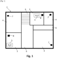
- room 2 comprises several rooms 3, 4, 6 separated by walls or partitions.
- the rooms 3, called wet rooms, are provided with at least one water inlet 5.
- the wet rooms 3 are for example a kitchen, a bathroom, a shower room, sanitary facilities, etc.
- the living rooms 4 are for example a living room or a bedroom.
- the rooms 6 are for example an entrance, a hallway, a landing, a hallway or a stairwell.
- Room 2 can for example include a kitchen open to a living room with an entrance, so that rooms 3, 4 and 6 are grouped together in a single volume.
- room 2 includes at least one living room 4 and one circulation room 6.
- room 2 may include a controlled mechanical ventilation device (VMC).
- VMC controlled mechanical ventilation device
- the VMC device comprises at least one air inlet 7 and at least one air extraction vent 8.
- each air inlet 7 is installed in one of the living rooms 4, and each extraction vent 8 is installed in one of the wet rooms 3.
- each living room 4 comprises one or more inlets of air 7.
- Each extraction vent 8 allows the extraction to the outside of a flow of air housed in the respective wet room 3, so as to create a depression in the room 2.
- Each inlet 7 allows the introduction into the room respective life 4 of an air flow, called fresh air (not shown), from the outside. The new air flow introduced makes it possible to compensate for the volume of air extracted by the extraction vent 8.
- the fresh air flow sweeps the air already present in room 4 so as to form a mixture of fresh air and air already present in room 4. This phenomenon is known as “dilution”.
- the mixture created continues towards the rooms 3 through, for example, undercuts of the doors or the transfer grids. In the wet rooms 3, the mixture can be extracted to the outside through the extraction vents 8.
- the circulation rooms 6 have no air inlet 7.
- the air present in each circulation room 6 is formed from the dilution of the air flows from each living room 4 due to the depression generated by the extraction of the air flow by the VMC device in damp rooms 3.
- the VMC device thus ensures a permanent renewal of air by sweeping in room 2.
- System 1 is installed in room 2.
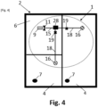
- room 2 includes a living room 4 and a circulation room 6.
- room 2 includes a circulation room 6 and two life rooms 4. It is of course possible to have a room 2 having any other number of life rooms 4 and any other number of circulation rooms 6.
- the composition of the air can be different depending, for example, on an occupancy rate, on an activity carried out at the interior, ventilation, etc.
- a quantity (or concentration) of at least one constituent of air differs between the different rooms 4, or in the same room 4 at different times.
- the air in the circulation room 6 is formed by dilution of the air flows from the living room(s) 4.
- a range of predetermined values can be defined for each constituent of the air.
- the predetermined range of values corresponds for example to a range of values of the quantity of the constituent of the air outside of which discomfort or health risks appear for an occupant of the living room 4.
- a quantity of the respective constituent of the air housed in the circulation room 6 is within a range of predetermined values, while in the living room(s) 4 a quantity of the same constituent of the air is outside the predetermined value range. This does not exclude that the room 2 includes other living rooms 4 in which the quantity of this constituent of the air is included, or potentially included, in the range of predetermined values.
- the constituent of the air is in particular an element or a compound which can cause the appearance of discomfort or health risks for the occupant of the living room 4.
- the inorganic compound(s) are, for example, carbon dioxide (CO 2 ), carbon monoxide (CO), ozone (O 3 ), nitrogen monoxide (NO), nitrogen dioxide (NO 2 ) and/or radon, among others.
- the volatile organic compound(s) are, for example, alcohols, aldehydes, ketones, hydrocarbons and/or terpenes, among others.
- the volatile organic compound(s) are, for example, benzene, formaldehyde, naphthalene, trichloroethylene, tetrachloroethylene, hydrocyanic acid, acetaldehyde, acrolein, ethylbenzene and/or toluene, among others.
- the semi-volatile organic compound(s) are for example phthalates, polycyclic aromatic hydrocarbons, musks and/or pesticides, among others.
- micro-organism is meant a living organism invisible to the naked eye, such as viruses or bacteria for example.
- particle is meant any solid or liquid compound suspended in the air of each of the parts 4, 6.
- the particles can be, for example, fine particles having an aeraulic diameter less than or equal to 10 ⁇ m.
- the quantity of water vapor at the given temperature determines a relative humidity in the room 4, 6.
- the relative humidity is defined as a ratio between a partial pressure of a water vapor contained in the air of each part 4, 6 at the given temperature on a saturation vapor pressure in the part 4, 6 at the given temperature.
- the range of predetermined values is preferably between a zero value and a higher value of quantity of the constituent of the matching tune.
- the upper value can be equal to 1000 ppm, or even equal to 5000 ppm.
- the relative humidity is between 30% and 70%, more preferably between 40% and 60%.
- 70% relative humidity there is, for example, a risk of deterioration of room 2, in particular by the proliferation of bacteria, or condensation and water infiltration in the walls.
- 30% relative humidity there is, for example, a risk of loss of comfort, or even a health risk, for the occupant of room 2.
- the occupant may, for example, experience drying of the mucous membranes due to dry conditions. in room 2.
- System 1 comprises at least one return assembly 9, one air diffusion assembly 10 and at least one fan 11.
- the return assembly 9 comprises a return grille 12 and a return plenum 13.
- the return set 9 could of course only comprise the return grille 12 or the return plenum 13.
- the recovery assembly 9 is installed in a circulation room 6.
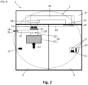
- the take-up assembly 9 When the system 1 is activated, the take-up assembly 9 is configured to suck in from the circulation part 6 a flow of air 14, called the flow of recycled air, visible on the picture 2 .
- the flow of recycled air 14 sucked in by the recovery assembly 9 can be constant or variable during operation of the system 1.
- the assembly of return 9 can be configured to draw in the recycled air flow 14 during one or more time slot(s) of operation of system 1.
- the diffusion assembly 10 comprises at least one network 15 comprising one or more ducts 18.
- duct is meant any type of duct allowing air to be transported.
- the diffusion assembly 10 also comprises at least one air diffuser 16.
- the air diffuser 16 is installed in the living room 4. On the picture 2 , the air diffuser 16 is installed against a false ceiling 17 of the living room 4, but it could be installed in any other position in the living room 4. Each living room 4 can be provided with one or more air diffusers 16.
- the diffusion assembly 10 may further comprise a distribution box 28 making it possible to connect all the ducts 18 to the return assembly 9.
- the distribution box 28 is provided with a heat treatment device which will be detailed below.
- Each sheath 18 extends between the distribution box 28 and a respective living room 4.
- Each duct 18 can for example be connected to the air diffuser 16 installed in the respective living room 4.
- the network 15 can extend between the recovery assembly 9 and several living rooms 4.
- the network 15 is installed in the false ceiling 17, but any other arrangement is possible.
- the diffusion assembly 10 is configured to introduce the flow of recycled air 14 into the living room(s) 4.
- the flow of recycled air 14 moves inside each duct 18 up to 'to be introduced into the corresponding living room 4, where a mixture between the recycled air flow 14 and the air already present in the living room 4 occurs.
- the diffusion assembly 10 is thus intended to fluidically connect the recovery assembly 9 to one or more living rooms 4.
- the diffusion assembly 10 may further comprise at least one member 19 for regulating the flow of recycled air 14 which enters the living room 4.
- the regulating member 19 may for example be a shutter or a damper with iris.
- the regulating member 19 is installed in each duct 18 or at the outlet of the distribution box 28, or it is associated with the air diffuser 16.
- the regulating member 19 is advantageously movable between a completely open position and a position of obstruction of the respective sheath 18. In the fully open position, the flow of recycled air 14 can pass through the duct 18 to the respective living room 4. In the obstructed position, the flow of recycled air 14 cannot pass through the duct 18, which prevents the flow of recycled air 14 from arriving in the respective living room 4.
- each regulating member 19 is independent of the other regulating members 19.
- certain regulating members 19 can be in the completely open position. and others in the completely closed position, which makes it possible to define towards which living rooms 4 the flow of recycled air 14 is directed.
- the introduction of the recycled air flow 14 can for example be favored in the living rooms 4 having higher quantities of the chosen air constituent.
- the regulating member 19 can assume one or more intermediate positions.
- a recirculated air flow which passes through the respective duct 18 is lower compared to the fully open position.
- the recirculated air flow corresponds to an amount of the recirculated air flow 14 which passes through the respective duct 18 per unit time.
- the flow of recycled air 14 which arrives in the living room 4 can be regulated with respect to the fully open position.
- the position of each regulating member 19 being independent of the other regulating members 19, a distribution of the flow of recycled air 14 in each living room 4 can also be controlled.
- the introduction of the flow of recycled air into the living room 4 aims to bring the quantity of the constituent air chosen inside the living room 4 from the range of predetermined values.
- a level of air quality is improved inside the living room 4, and the inconvenience and/or health risks for the occupant of the living room 4 are limited.
- system 1 further comprises at least one fan 11.
- the fan 11 is intended to put a flow of air, in particular the flow of recycled air 14, in motion between the return assembly 9 and each air diffuser 16.
- the system 1 comprises a ventilation orifice 24, also called “fresh air inlet”, which connects the outside of the room with a duct 27, also called “fresh air duct”.
- a ventilation orifice 24 also called “fresh air inlet”
- the duct 27 connects the orifice 24 and the return plenum 13, but it could connect the orifice 24 directly to the distribution box 28, as illustrated in the figure 5 .
- the orifice 24 and the duct 27 are intended to introduce a flow of new air 25 into the network 15.
- the flow of new air 25 can thus be introduced into the living room 4.
- Non-return valves 29 can be installed between the orifice 24 and the plenum 13 as well as in the fresh air duct 27 if this duct 27 is not used.
- fan (not shown) for blowing the fresh air flow 25 can be installed in the duct 27.
- system 1 When system 1 includes orifice 24 connected to plenum 13 or box 28, living room 4 may have no air inlet 7.
- the system 1 can further comprise a control means 20.
- the control means 20 can comprise a man-machine interface 21, such as a physical or virtual button.
- the interface 21 allows an occupant of the living room 4 to put the system 1 into operation, to define a mode of operation of the system and/or to define at least one operating range of the system 1, among others.
- An example of operating mode of system 1 can be a mode, called night mode, for which system 1 is only activated during the night and the flow of recycled air 14 is constant.
- night mode for which system 1 is only activated during the night and the flow of recycled air 14 is constant.
- the flow of recycled air is adjusted so as to limit noise pollution.
- an operating mode of the system 1 can be a mode, called purification mode, for which the flow of recycled air 14 sucked in is maximum, which makes it possible to introduce a maximum quantity of recycled air into the living room. 4.
- purification mode for which the flow of recycled air 14 sucked in is maximum, which makes it possible to introduce a maximum quantity of recycled air into the living room. 4.
- Another example of operating mode of system 1 can be a mode, called automatic mode.
- control means 20 may include one or more sensor(s) 22 intended to be installed in the living room 4. In some cases, at least one sensor 22 is also installed in circulation room 6.
- Some sensors 22 may be a sensor of the quantity of the constituent of the air in the room 4, 6 chosen from among the constituents of the air indicated previously.
- some sensors 22 may for example be a sensor of a quantity or a concentration of an inorganic compound, such as CO 2 , of microorganisms or of relative humidity in the respective part 4, 6.
- the sensor 22 in the living room 4 sends a signal to activate the system 1 when the quantity of the constituent of the air chosen in the living room 4 is outside the range of predetermined values.
- the recycled air flow 14 is thus sucked in from the circulation room 6 and introduced into the living room(s) 4.
- Other sensors 22 can be a presence detector.
- the presence of occupants generally causes an increase in the amount of certain air constituents in the occupied room.
- bio-effluents such as CO 2
- microorganisms from the body which are transferred to the air of the occupied living room. Therefore, the presence detector can send a signal making it possible to activate the system 1 without the need to measure the quantity of the constituent of the air chosen inside this room 4, and possibly, inside the room of circulation 6.
- Each sensor 22 can also send a signal to activate the system 1 when a difference in quantity of the constituent of the chosen air and/or in the occupancy rate exists between several living rooms 4 for which the quantity of the constituent of the air air housed therein is however within the range of predetermined values. In this way, a homogenization of the level of air quality is achieved in 4 rooms.
- the system 1 can also receive a signal to deactivate when the respective sensor 22 detects that in the respective living room 4 the quantity of the selected air constituent and/or the occupancy rate no longer cause discomfort or health risk for the occupants.
- System 1 can also be activated if the occupant of a room provided with a man-machine interface 21 manually controls the activation of system 1.
- the control means 20 therefore makes it possible to activate and/or deactivate the system, and/or to determine an operating mode of the system. Independently of the operating mode of the system, the control means 20 can be configured to activate the system 1 only during one or more time slots.
- the sensors 22 can also be designed to send a signal to the VMC device in order to increase the flow of air extracted by the extraction vent 8.
- the sensor 22 in the living room 4 detects that the quantity component of the air chosen in this living room 4 is outside the range of predetermined values, the sensor 22 can send the signal making it possible to increase the flow of air extracted by the VMC device.
- the introduction of fresh air through the air inlets 7 is thus favored. This fresh air flow contributes to the dilution phenomenon in room 2 as explained previously.
- the extraction of the air flow from the room can be done for a given time, for example for 30 minutes.
- the system 1 may further comprise an air flow purification treatment device 23, shown in figure figure 2 .
- purification it is meant for example that the recycled air flow 14 is completely or partially freed of impurities, such as microbes, viruses, bacteria, insects, microorganisms, particles, volatile or semi-volatile organic compounds. volatiles, polluting gas molecules, inorganic compounds, etc. More precisely, the purification treatment device 23 according to the present invention makes it possible to completely or partially rid the flow of recycled air 14 of the constituents of the air indicated above.
- the purification treatment device 23 is arranged so as to be traversed by the flow of recycled air 14. On the example of the picture 2 , it is placed inside the return plenum 13, which makes it easily accessible for maintenance purposes. Alternatively, the purification treatment device 23 is arranged in any other position through which the recycled air flow 14 passes, for example inside the network 15.
- the purification treatment can be a physico-chemical treatment of the recycled air flow 14, for example by filtration of the mechanical or gravimetric type.
- the purification treatment device 23 can therefore comprise at least one filter allowing the filtration of the constituent of the air chosen in the flow of recycled air 14.
- the physico-chemical treatment can also be by adsorption, ionization and capture, electrostatic filtration, ozonization, plasma, photocatalysis, biofiltration, use of a disinfectant product or radiation, use of activated carbon, use of UV lamps, etc.
- the network 15 being able to be connected to several living rooms 4 via the ducts 18, the system 1 according to the present invention makes it possible to carry out centralized processing of several living rooms 4.
- the system 1 makes it possible to dilute the concentration of the constituent of the air chosen in the living rooms 4 without the need to breathe more fresh air into the room. This therefore makes it possible to limit the concentrations of pollutants while limiting energy consumption and thermal losses. More precisely, the system 1 makes it possible to smooth the level of air pollution of the whole of the room 2, while limiting the energy consumption and the thermal losses.
Landscapes
- Engineering & Computer Science (AREA)
- Chemical & Material Sciences (AREA)
- Combustion & Propulsion (AREA)
- Mechanical Engineering (AREA)
- General Engineering & Computer Science (AREA)
- Human Computer Interaction (AREA)
- Ventilation (AREA)
- Jet Pumps And Other Pumps (AREA)
Applications Claiming Priority (1)
| Application Number | Priority Date | Filing Date | Title |
|---|---|---|---|
| FR2111976A FR3128884B1 (fr) | 2021-11-10 | 2021-11-10 | Systeme de recyclage d’air pour un local |
Publications (1)
| Publication Number | Publication Date |
|---|---|
| EP4180733A1 true EP4180733A1 (de) | 2023-05-17 |
Family
ID=79171174
Family Applications (1)
| Application Number | Title | Priority Date | Filing Date |
|---|---|---|---|
| EP22206462.8A Pending EP4180733A1 (de) | 2021-11-10 | 2022-11-09 | Luftrückführungssystem für einen raum |
Country Status (2)
| Country | Link |
|---|---|
| EP (1) | EP4180733A1 (de) |
| FR (1) | FR3128884B1 (de) |
Citations (6)
| Publication number | Priority date | Publication date | Assignee | Title |
|---|---|---|---|---|
| GB1263655A (en) * | 1969-06-12 | 1972-02-16 | Gustavsbergs Fabriker Ab | Method of heating a dwelling unit with preheated air in combination with ventilation |
| JPH03164647A (ja) * | 1989-11-22 | 1991-07-16 | Mitsubishi Electric Corp | 空気調和機 |
| GB2261964A (en) * | 1991-11-30 | 1993-06-02 | Toshiba Kk | Air conditioning apparatus for distributing primarily-conditioned air to rooms |
| FR2839143A1 (fr) * | 2002-04-25 | 2003-10-31 | Aldes Aeraulique | Bloc de distribution et/ou de melange d'air pour une installation de climatisation reversible air/air a detente directe de type"gainable" |
| WO2007110505A2 (fr) * | 2006-03-28 | 2007-10-04 | Aldes Aeraulique | Procede et systeme de chauffage / rafraichissement et ventilation d'un local |
| FR3087522A1 (fr) * | 2018-10-23 | 2020-04-24 | France Air | Systeme de traitement par vecteur air |
-
2021
- 2021-11-10 FR FR2111976A patent/FR3128884B1/fr active Active
-
2022
- 2022-11-09 EP EP22206462.8A patent/EP4180733A1/de active Pending
Patent Citations (6)
| Publication number | Priority date | Publication date | Assignee | Title |
|---|---|---|---|---|
| GB1263655A (en) * | 1969-06-12 | 1972-02-16 | Gustavsbergs Fabriker Ab | Method of heating a dwelling unit with preheated air in combination with ventilation |
| JPH03164647A (ja) * | 1989-11-22 | 1991-07-16 | Mitsubishi Electric Corp | 空気調和機 |
| GB2261964A (en) * | 1991-11-30 | 1993-06-02 | Toshiba Kk | Air conditioning apparatus for distributing primarily-conditioned air to rooms |
| FR2839143A1 (fr) * | 2002-04-25 | 2003-10-31 | Aldes Aeraulique | Bloc de distribution et/ou de melange d'air pour une installation de climatisation reversible air/air a detente directe de type"gainable" |
| WO2007110505A2 (fr) * | 2006-03-28 | 2007-10-04 | Aldes Aeraulique | Procede et systeme de chauffage / rafraichissement et ventilation d'un local |
| FR3087522A1 (fr) * | 2018-10-23 | 2020-04-24 | France Air | Systeme de traitement par vecteur air |
Also Published As
| Publication number | Publication date |
|---|---|
| FR3128884A1 (fr) | 2023-05-12 |
| FR3128884B1 (fr) | 2025-04-25 |
Similar Documents
| Publication | Publication Date | Title |
|---|---|---|
| US5656242A (en) | Air purifier device | |
| Darlington1* et al. | The biofiltration of indoor air: implications for air quality | |
| US20080274012A1 (en) | Method for abatement of allergens, pathogens and volatile organic compounds | |
| US9885487B2 (en) | Humidifier utilizing filtered water | |
| FR3087522A1 (fr) | Systeme de traitement par vecteur air | |
| US20220072178A1 (en) | Scent control device and methods for treating an environment | |
| KR20200018057A (ko) | 워터 커튼 형성을 위한 분무 노즐과 구멍이나 바 타입 워터받이 샤워, 초음파 진동자, 자외선램프, 탈취 필터, 방범 및 방충기능 등을 포함하는 다기능 공기청정기 | |
| WO2014020246A1 (fr) | Dispositif de ventilation mecanique centralisee a double flux anti aero-contaminant automatise en fonction d'un controle permanent de la qualite de l'air interieur et exterieur d'un espace habitable ferme | |
| KR20150139066A (ko) | 실내 공기 정화장치 | |
| JP5301772B2 (ja) | 空調システム | |
| KR101111489B1 (ko) | 공기 정화 장치 | |
| EP4063751B1 (de) | Verfahren zur steuerung eines lüftungs-, heizungs-, klimatisierungs- und/oder luftreinigungssystems | |
| FR3128884A1 (fr) | Systeme de recyclage d’air pour un local | |
| FR3097031A1 (fr) | systeme de contrôle de la qualité de l’air dans un espace intérieur | |
| JP2005290754A (ja) | 扉用換気装置 | |
| FR2974404A1 (fr) | Systeme de ventilation | |
| KR102196737B1 (ko) | 덕트관 청소 기능이 부설된 공동주택 건축물의 미세먼지 정화시스템 | |
| FR3106654A1 (fr) | Unité de confort aéraulique, installation de ventilation et de traitement d’air associée | |
| JP2014109432A (ja) | 壁ならびに高清浄部屋システムおよびその製造方法ならびに建築物 | |
| EP2442041B1 (de) | Mechanische Belüftungsinstallation durch feuchtigkeitsregulierte Belüftung, und zugehöriges Verfahren | |
| GB2569111A (en) | A positive input ventilation system with active carbon filter | |
| US7300624B2 (en) | Method of disinfecting a building air supply | |
| JP2017503642A (ja) | Pco反応を実行するための方法及び装置、並びに該装置を有する空気清浄器 | |
| Jokl | Evaluation of indoor air quality using the decibel concept | |
| KR100530903B1 (ko) | 이동형 탈취장치 |
Legal Events
| Date | Code | Title | Description |
|---|---|---|---|
| PUAI | Public reference made under article 153(3) epc to a published international application that has entered the european phase |
Free format text: ORIGINAL CODE: 0009012 |
|
| STAA | Information on the status of an ep patent application or granted ep patent |
Free format text: STATUS: THE APPLICATION HAS BEEN PUBLISHED |
|
| AK | Designated contracting states |
Kind code of ref document: A1 Designated state(s): AL AT BE BG CH CY CZ DE DK EE ES FI FR GB GR HR HU IE IS IT LI LT LU LV MC ME MK MT NL NO PL PT RO RS SE SI SK SM TR |
|
| STAA | Information on the status of an ep patent application or granted ep patent |
Free format text: STATUS: REQUEST FOR EXAMINATION WAS MADE |
|
| 17P | Request for examination filed |
Effective date: 20230524 |
|
| RBV | Designated contracting states (corrected) |
Designated state(s): AL AT BE BG CH CY CZ DE DK EE ES FI FR GB GR HR HU IE IS IT LI LT LU LV MC ME MK MT NL NO PL PT RO RS SE SI SK SM TR |
|
| STAA | Information on the status of an ep patent application or granted ep patent |
Free format text: STATUS: EXAMINATION IS IN PROGRESS |
|
| 17Q | First examination report despatched |
Effective date: 20250522 |