EP4063684A1 - Druck- und rückhaltevorrichtung für eine feder - Google Patents
Druck- und rückhaltevorrichtung für eine feder Download PDFInfo
- Publication number
- EP4063684A1 EP4063684A1 EP22161551.1A EP22161551A EP4063684A1 EP 4063684 A1 EP4063684 A1 EP 4063684A1 EP 22161551 A EP22161551 A EP 22161551A EP 4063684 A1 EP4063684 A1 EP 4063684A1
- Authority
- EP
- European Patent Office
- Prior art keywords
- spring
- hook
- pressing
- retaining
- assembly
- Prior art date
- Legal status (The legal status is an assumption and is not a legal conclusion. Google has not performed a legal analysis and makes no representation as to the accuracy of the status listed.)
- Pending
Links
Images


Classifications
-
- F—MECHANICAL ENGINEERING; LIGHTING; HEATING; WEAPONS; BLASTING
- F16—ENGINEERING ELEMENTS AND UNITS; GENERAL MEASURES FOR PRODUCING AND MAINTAINING EFFECTIVE FUNCTIONING OF MACHINES OR INSTALLATIONS; THERMAL INSULATION IN GENERAL
- F16F—SPRINGS; SHOCK-ABSORBERS; MEANS FOR DAMPING VIBRATION
- F16F1/00—Springs
- F16F1/02—Springs made of steel or other material having low internal friction; Wound, torsion, leaf, cup, ring or the like springs, the material of the spring not being relevant
- F16F1/04—Wound springs
- F16F1/12—Attachments or mountings
- F16F1/121—Attachments or mountings adjustable, e.g. to modify spring characteristics
-
- B—PERFORMING OPERATIONS; TRANSPORTING
- B25—HAND TOOLS; PORTABLE POWER-DRIVEN TOOLS; MANIPULATORS
- B25B—TOOLS OR BENCH DEVICES NOT OTHERWISE PROVIDED FOR, FOR FASTENING, CONNECTING, DISENGAGING OR HOLDING
- B25B27/00—Hand tools, specially adapted for fitting together or separating parts or objects whether or not involving some deformation, not otherwise provided for
- B25B27/14—Hand tools, specially adapted for fitting together or separating parts or objects whether or not involving some deformation, not otherwise provided for for assembling objects other than by press fit or detaching same
- B25B27/30—Hand tools, specially adapted for fitting together or separating parts or objects whether or not involving some deformation, not otherwise provided for for assembling objects other than by press fit or detaching same positioning or withdrawing springs, e.g. coil or leaf springs
- B25B27/302—Hand tools, specially adapted for fitting together or separating parts or objects whether or not involving some deformation, not otherwise provided for for assembling objects other than by press fit or detaching same positioning or withdrawing springs, e.g. coil or leaf springs coil springs other than torsion coil springs
- B25B27/304—Hand tools, specially adapted for fitting together or separating parts or objects whether or not involving some deformation, not otherwise provided for for assembling objects other than by press fit or detaching same positioning or withdrawing springs, e.g. coil or leaf springs coil springs other than torsion coil springs by compressing coil springs
-
- B—PERFORMING OPERATIONS; TRANSPORTING
- B25—HAND TOOLS; PORTABLE POWER-DRIVEN TOOLS; MANIPULATORS
- B25B—TOOLS OR BENCH DEVICES NOT OTHERWISE PROVIDED FOR, FOR FASTENING, CONNECTING, DISENGAGING OR HOLDING
- B25B27/00—Hand tools, specially adapted for fitting together or separating parts or objects whether or not involving some deformation, not otherwise provided for
- B25B27/14—Hand tools, specially adapted for fitting together or separating parts or objects whether or not involving some deformation, not otherwise provided for for assembling objects other than by press fit or detaching same
- B25B27/30—Hand tools, specially adapted for fitting together or separating parts or objects whether or not involving some deformation, not otherwise provided for for assembling objects other than by press fit or detaching same positioning or withdrawing springs, e.g. coil or leaf springs
-
- F—MECHANICAL ENGINEERING; LIGHTING; HEATING; WEAPONS; BLASTING
- F16—ENGINEERING ELEMENTS AND UNITS; GENERAL MEASURES FOR PRODUCING AND MAINTAINING EFFECTIVE FUNCTIONING OF MACHINES OR INSTALLATIONS; THERMAL INSULATION IN GENERAL
- F16F—SPRINGS; SHOCK-ABSORBERS; MEANS FOR DAMPING VIBRATION
- F16F1/00—Springs
- F16F1/02—Springs made of steel or other material having low internal friction; Wound, torsion, leaf, cup, ring or the like springs, the material of the spring not being relevant
- F16F1/04—Wound springs
- F16F1/12—Attachments or mountings
- F16F1/122—Attachments or mountings where coils, e.g. end coils, of the spring are rigidly clamped or similarly fixed
-
- F—MECHANICAL ENGINEERING; LIGHTING; HEATING; WEAPONS; BLASTING
- F16—ENGINEERING ELEMENTS AND UNITS; GENERAL MEASURES FOR PRODUCING AND MAINTAINING EFFECTIVE FUNCTIONING OF MACHINES OR INSTALLATIONS; THERMAL INSULATION IN GENERAL
- F16F—SPRINGS; SHOCK-ABSORBERS; MEANS FOR DAMPING VIBRATION
- F16F1/00—Springs
- F16F1/02—Springs made of steel or other material having low internal friction; Wound, torsion, leaf, cup, ring or the like springs, the material of the spring not being relevant
- F16F1/04—Wound springs
- F16F1/12—Attachments or mountings
- F16F1/128—Attachments or mountings with motion-limiting means, e.g. with a full-length guide element or ball joint connections; with protective outer cover
-
- F—MECHANICAL ENGINEERING; LIGHTING; HEATING; WEAPONS; BLASTING
- F16—ENGINEERING ELEMENTS AND UNITS; GENERAL MEASURES FOR PRODUCING AND MAINTAINING EFFECTIVE FUNCTIONING OF MACHINES OR INSTALLATIONS; THERMAL INSULATION IN GENERAL
- F16F—SPRINGS; SHOCK-ABSORBERS; MEANS FOR DAMPING VIBRATION
- F16F1/00—Springs
- F16F1/02—Springs made of steel or other material having low internal friction; Wound, torsion, leaf, cup, ring or the like springs, the material of the spring not being relevant
- F16F1/04—Wound springs
- F16F1/12—Attachments or mountings
- F16F1/13—Attachments or mountings comprising inserts and spacers between the windings for changing the mechanical or physical characteristics of the spring
-
- B—PERFORMING OPERATIONS; TRANSPORTING
- B60—VEHICLES IN GENERAL
- B60G—VEHICLE SUSPENSION ARRANGEMENTS
- B60G2206/00—Indexing codes related to the manufacturing of suspensions: constructional features, the materials used, procedures or tools
- B60G2206/01—Constructional features of suspension elements, e.g. arms, dampers, springs
- B60G2206/90—Maintenance
- B60G2206/92—Tools or equipment used for assembling
- B60G2206/921—Coil spring compressor
-
- F—MECHANICAL ENGINEERING; LIGHTING; HEATING; WEAPONS; BLASTING
- F16—ENGINEERING ELEMENTS AND UNITS; GENERAL MEASURES FOR PRODUCING AND MAINTAINING EFFECTIVE FUNCTIONING OF MACHINES OR INSTALLATIONS; THERMAL INSULATION IN GENERAL
- F16F—SPRINGS; SHOCK-ABSORBERS; MEANS FOR DAMPING VIBRATION
- F16F2230/00—Purpose; Design features
- F16F2230/0005—Attachment, e.g. to facilitate mounting onto confer adjustability
-
- F—MECHANICAL ENGINEERING; LIGHTING; HEATING; WEAPONS; BLASTING
- F16—ENGINEERING ELEMENTS AND UNITS; GENERAL MEASURES FOR PRODUCING AND MAINTAINING EFFECTIVE FUNCTIONING OF MACHINES OR INSTALLATIONS; THERMAL INSULATION IN GENERAL
- F16F—SPRINGS; SHOCK-ABSORBERS; MEANS FOR DAMPING VIBRATION
- F16F2230/00—Purpose; Design features
- F16F2230/0041—Locking; Fixing in position
Definitions
- the invention relates to the technical field of vehicle assembly equipment, and particularly to a pressing and retaining device for a spring.
- Coil springs are springs subjected to torsional deformation in vehicles. In order to adapt to production of various vehicle models of different platforms on the same product line and to ensure that rear axle assemblies can be smoothly assembled, it is necessary to compress and retain rear coil springs.
- the coil spring In order to smoothly assemble the rear axle assembly, in a current technical solution, the coil spring is compressed by means of external force and directly mounted on a vehicle body. Therefore, it is necessary to use a large-sized tooling to cooperatively complete control of the vehicle body during compression and retaining of the spring, in order to smoothly assemble the coil spring.
- the invention provides a pressing and retaining device for a spring, the pressing and retaining device comprising a spring compression assembly and a spring retaining assembly.
- the spring compression assembly is configured to be capable of compressing the spring into a set state.
- the spring retaining assembly is configured to be capable of fixing the spring and maintaining a compressed state of the spring when the spring is compressed into the set state, and to be capable of still fixing the spring and maintaining the compressed state of the spring when the spring retaining assembly and the spring are disengaged as a whole from the spring compression assembly.
- the spring retaining assembly comprises a first connecting portion and a second connecting portion, the first connecting portion is connected to the second connecting portion, the first connecting portion is arranged at an upper half portion of the spring, and the second connecting portion is correspondingly arranged at a lower half portion of the spring.
- the spring retaining assembly further comprises a connecting rod via which the first connecting portion is connected to the second connecting portion;
- the first connecting portion comprises a first hook connecting block, and a first hook and a second hook which are hinged to the first hook connecting block, and the first hook connecting block is provided with a first mounting hole;
- the second connecting portion comprises a second hook connecting block, and a third hook and a fourth hook which are hinged to the second hook connecting block, and the second hook connecting block is provided with a second mounting hole.
- the first mounting hole is a through hole
- the second mounting hole is a threaded hole
- the connecting rod is correspondingly provided with a boss and a thread.
- the first mounting hole and the second mounting hole are both threaded holes
- the connecting rod is correspondingly provided with threads.
- a hexagonal prism is further provided at an end portion of the connecting rod.
- the first hook and the third hook are correspondingly arranged on the same side
- the second hook and the fourth hook are correspondingly arranged on the same side
- the spring has a length along which the spring is clamped by the first hook and the third hook, which is equal to a length along which the spring is clamped by the second hook and the fourth hook
- the heights of mounting positions of the first hook and the second hook are different in an axial direction of the connecting rod
- the heights of mounting positions of the third hook and the fourth hook are correspondingly different in the axial direction of the connecting rod.
- the spring retaining assembly is a U-shaped lock.
- the spring compression assembly comprises a rack, a driving device, a fixing seat arranged on the rack, and a pressing plate connected to the driving device.
- the driving device is configured to be capable of driving the pressing plate to move close to or away from the fixing seat.
- the fixing seat and the pressing plate are provided with spring limiting grooves.
- an outer side portion where the spring is placed is further provided with a clamping block.
- the pressing and retaining device for a spring comprises a spring compression assembly and a spring retaining assembly.
- the spring compression assembly is configured to be capable of compressing the spring into a set state.
- the spring retaining assembly is configured to be capable of fixing the spring and maintaining a compressed state of the spring when the spring is compressed into the set state, and to be capable of still fixing the spring and maintaining the compressed state of the spring when the spring retaining assembly and the spring are disengaged as a whole from the spring compression assembly.
- the invention makes it possible to first compress the spring to the set state, and then fix the spring and maintain the compressed state of the spring after the spring is compressed to the set state. Moreover, the spring retaining assembly and the spring can be disengaged from the spring compression assembly, and the spring retaining assembly can still fix the spring and maintain the compressed state of the spring after the spring retaining assembly and the spring are disengaged from the spring compression assembly. Hence, the invention makes it possible to remove the spring retaining assembly and the spring, which is compressed into the set state, as a whole from the spring compression assembly, and to use the whole for the assembly of a rear axle assembly of a vehicle.
- the terms “mount”, “engage” and “connect” should be interpreted in a broad sense unless explicitly defined and limited otherwise, which, for example, may mean a fixed connection, a detachable connection or an integral connection; may mean a mechanical connection or an electrical connection; and may mean a direct connection, an indirect connection by means of an intermediary, or internal communication between two elements.
- the specific meaning of the above-mentioned terms in the invention can be interpreted according to the specific situation.
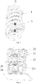
- Fig. 1 is a schematic structural diagram of the spring pressing and retaining device.
- the invention provides a pressing and retaining device for a spring.
- the pressing and retaining device comprises a spring compression assembly 2 and a spring retaining assembly 1.
- the spring compression assembly 2 is configured to be capable of compressing the spring 3 into a set state.
- the spring retaining assembly 1 is configured to be capable of fixing the spring and maintaining a compressed state of the spring 3 when the spring 3 is compressed into the set state, and to be capable of still fixing the spring and maintaining the compressed state of the spring 3 when the spring retaining assembly 1 and the spring 3 are disengaged as a whole from the spring compression assembly 2.
- the invention makes it possible to remove the spring retaining assembly 1 and the spring 3, which is compressed into the set state, as a whole from the spring compression assembly 2, and to use the whole for the assembly of a rear axle assembly of a vehicle. Accordingly, during the assembly of the rear axle assembly, there is no longer a need for a large-sized tooling to compress and retain the spring, so that the pressing and retaining of the spring are easy to operate, and the safety during operation is also improved.
- the spring retaining assembly 1 comprises a first connecting portion 11 and a second connecting portion 12.
- the first connecting portion 11 is connected to the second connecting portion 12, the first connecting portion 11 is arranged at an upper half portion of the spring 3, and the second connecting portion 12 is correspondingly arranged at a lower half portion of the spring 3.
- the spring 3 is axially fixed by providing the first connecting portion 11 and the second connecting portion 12 connected to each other at the upper half portion and the lower half portion of the spring 3 respectively.
- the spring retaining assembly 1 may further comprise a connecting rod 13.
- the first connecting portion 11 is connected to the second connecting portion 12 via the connecting rod 13.
- the first connecting portion 11 comprises a first hook connecting block 111, and a first hook 112 and a second hook 113 which are hinged to the first hook connecting block 111.
- the first hook connecting block 111 is provided with a first mounting hole 1111.
- the second connecting portion 12 comprises a second hook connecting block 121, and a third hook 122 and a fourth hook 123 which are hinged to the second hook connecting block 121.
- the second hook connecting block 121 is provided with a second mounting hole 1211.
- the first mounting hole 1111 is a through hole
- the second mounting hole 1211 is a threaded hole.
- the connecting rod 13 is correspondingly provided with a boss 131 and a thread 132, and a hexagonal prism 133 is further arranged at an end portion of the connecting rod 13.
- one end of the connecting rod 13 penetrates through the first connecting portion 11 through the first mounting hole 1111, and the connecting rod 13 is fixed to the first connecting portion 11 by means of the boss 131 on the connecting rod 13, and the other end of the connecting rod 13 is in threaded connection with the second connecting portion 12 through the second mounting hole 1211.
- first hook 112 and the second hook 113 are mounted at the upper half portion of the spring 3, and the third hook 122 and the fourth hook 123 are respectively correspondingly mounted at the lower half portion of the spring 3.
- the spring 3 compressed into the set state is clamped by adjusting the hexagonal prism 133 at the end portion of the connecting rod 13.
- the above configuration has the following advantages: by hinging the first hook 112 and the second hook 113 to the first hook connecting block 111, hinging the third hook 122 and the fourth hook 123 to the second hook connecting block 121, mounting the first hook 112 and the second hook 113 to the upper half portion of the spring 3, and mounting the third hook 122 and the fourth hook 123 to the lower half portion of the spring 3, the spring 3 can be axially fixed, and the spring 3 can also be stressed uniformly during compression and retaining.
- the retaining function of the compressed state of the spring 3 can be achieved, and the distance between the first connecting portion 11 and the second connecting portion 12 in a retaining state can be easily adjusted, which is better suitable for maintaining the state of the spring 3 in different compressed states.
- the forms of the holes in the first hook connecting block 111 and the second hook connecting block 121 are described in this embodiment respectively by taking the first mounting hole 1111 being the through hole and the second connection hole 1211 being the threaded hole as an example, the forms of the holes in the first hook connecting block 111 and the second hook connecting block 121 in this embodiment are not limited thereto, as long as the connecting rod 13 is connected and fixed to the first hook connecting block 111 and the second hook connecting block 121 respectively.
- the first mounting hole 1111 and the second mounting hole 1211 are both threaded holes, and the connecting rod 13 is correspondingly provided with threads 132.
- the first mounting hole 1111 and the second mounting hole 1211 are both through holes, correspondingly, one end of the connecting rod is provided with the boss 131, and the other end thereof is provided with a nut as another detachable boss.
- the first hook 112 and the third hook 122 are correspondingly arranged on the same side
- the second hook 113 and the fourth hook 123 are correspondingly arranged on the same side
- the spring has a length along which the spring 3 is clamped by the first hook 112 and the third hook 122, which is equal to a length along which the spring 3 is clamped by the second hook 113 and the fourth hook 123
- the heights of mounting positions of the first hook 112 and the second hook 113 are different in an axial direction of the connecting rod 13
- the heights of mounting positions of the third hook 122 and the fourth hook 123 are correspondingly different in the axial direction of the connecting rod 13.
- the above configuration has the following advantages: since the spring 3 is helical, if it is not specially designed and straightforwardly, the first hook 112 and the second hook 113 are symmetrically designed, and the third hook 122 and the fourth hook 123 are symmetrically designed, parts of the spring 3 with different heights will be squeezed to the same horizontal plane, resulting in deflection of the spring.
- the first hook 112 and the second hook 113 are mounted at different height positions in the axial direction of the connecting rod 13, the length along which the spring 3 is clamped by the first hook 112 and the third hook 122 is equal to the length along which the spring 3 is clamped by the second hook 113 and the fourth hook 123, such that the spring 3 does not tilt during the compression and retaining.
- the spring 3 is stressed uniformly, and on the other hand, the safety of the spring 3 during the compression and retaining is also improved.
- the spring compression assembly 2 comprises a rack 21, a driving device 22, a fixing seat 24 arranged on the rack 21, and a pressing plate 23 connected to the driving device 22.
- the driving device 22 is configured to be capable of driving the pressing plate 23 to move close to or away from the fixing seat 24.
- the driving device 22 may be an electric or hydraulic push rod.
- the form of the driving device 22 in this embodiment is described by taking the electric or hydraulic push rod as an example, the form of the driving device 22 of this embodiment is not limited thereto, as long as the effect that the pressing plate 23 compresses the spring 3 can be achieved by applying an external force to the pressing plate 23.
- the fixing seat 24 and the pressing plate 23 are both provided with spring limiting grooves 231.
- the above configuration has the following advantages: by forming the spring limiting grooves 231 on the fixing seat 24 and the pressing plate 23, it is possible to vertically place the spring 3 in the axial direction thereof, reducing the degree of tilt of the spring 3 during the compression. Hence, on the one hand, the compression accuracy of the spring 3 is improved, and on the other hand, the safety of the spring 3 during pressing and retaining is also improved.
- an outer side portion where the spring 3 is placed is further provided with a clamping block 25.
- the above configuration has the following advantages: by providing the clamping block 25 at the outer side portion where the spring 3 is placed, it is possible to assist further precise positioning of the spring 3 placed in the spring limiting grooves 231 on the fixing seat 24 and the pressing plate 23, to further reduce offset of the spring 3 during the compression, thereby further improving the compression accuracy of the spring 3.
- the spring 3 in the compressed state is maintained in its compressed state, so that the spring retaining assembly 1 and the spring 3 can be disengaged as a whole from the spring compression assembly 2.
- the spring limiting grooves 231 formed on the fixing seat 24 and the pressing plate 23 of the spring compression assembly 2, and the clamping block 25 arranged on the outer side portion of the spring 3 accurate positioning of the spring 3 is achieved. Accordingly, the technical solution for pressing and retaining the spring 3 is easy to operate, and the compression accuracy of the spring 3 and the safety of the spring 3 are also improved during the compression and retaining.
- the spring retaining assembly is not limited to the above embodiment.
- the spring retaining assembly 1 comprises the first connecting portion 11 and the second connecting portion 12, but does not comprise the connecting rod 13.
- the first connecting portion 11 is connected to the second connecting portion 12, the first connecting portion 11 is arranged at the upper half portion of the spring 3, the second connecting portion 12 is correspondingly arranged at the lower half portion of the spring 3, and the first connecting portion 11 and the second connecting portion 12 are respectively provided with a snap groove 114 and a snap 124.
- the spring 3 is clamped between the first connecting portion 11 and the second connecting portion 12, and when the spring 3 is compressed into the set state, the first connecting portion 11 and the second connecting portion 12 are connected by means of the snap groove 114 on the first connecting portion 11 and the snap 124 on the second connecting portion 12.
- the spring 3 is axially fixed by providing the first connecting portion 11 and the second connecting portion 12 connected to each other at the upper half portion and the lower half portion of the spring 3 respectively.
- the spring retaining assembly 1 comprises a catch connecting block 14.
- a first catch 141 and a second catch 142 are separately hinged to the upper end of the catch connecting block 14, and a third catch 143 and a fourth catch 144 are separately hinged to the lower end of the catch connecting block 14.
- the first catch 141 and the second catch 142 are mounted at the upper half portion of the spring 3, and the third catch 143 and the fourth catch 144 are respectively correspondingly mounted at the lower half portion of the spring 3.
- the catch connecting block 14 is placed in the spring 3, the first catch 141 and the second catch 142 catch the upper half portion of the spring 3, while the third catch 143 and the fourth catch 144 catch the lower half portion of the spring 3.
- the spring retaining assembly 1 is a U-shaped lock 15.
- the U-shaped lock 15 is used to lock the compressed spring 3 when the spring 3 is compressed into the set state.
- the spring 3 compressed into the set state is locked by the U-shaped lock 15 to maintain the compressed state of the spring 3. This does not depart from the principle of the invention and therefore falls within the protection scope of the invention, as long as the spring retaining assembly 1 can retain the spring 3 in the compressed state.
Applications Claiming Priority (1)
| Application Number | Priority Date | Filing Date | Title |
|---|---|---|---|
| CN202110267839.1A CN113021264A (zh) | 2021-03-11 | 2021-03-11 | 用于弹簧的压装保持装置 |
Publications (1)
| Publication Number | Publication Date |
|---|---|
| EP4063684A1 true EP4063684A1 (de) | 2022-09-28 |
Family
ID=76469892
Family Applications (1)
| Application Number | Title | Priority Date | Filing Date |
|---|---|---|---|
| EP22161551.1A Pending EP4063684A1 (de) | 2021-03-11 | 2022-03-11 | Druck- und rückhaltevorrichtung für eine feder |
Country Status (3)
| Country | Link |
|---|---|
| US (1) | US20220288755A1 (de) |
| EP (1) | EP4063684A1 (de) |
| CN (1) | CN113021264A (de) |
Families Citing this family (1)
| Publication number | Priority date | Publication date | Assignee | Title |
|---|---|---|---|---|
| CN115383446A (zh) * | 2022-08-30 | 2022-11-25 | 安徽悦众车身装备有限公司 | 一种后桥弹簧压装设备 |
Citations (7)
| Publication number | Priority date | Publication date | Assignee | Title |
|---|---|---|---|---|
| US1389657A (en) * | 1920-07-02 | 1921-09-06 | John W Harsley | Combination spring-compressor and spring clamp |
| US3341175A (en) * | 1965-09-30 | 1967-09-12 | Charles E Branick | Spring compression tool |
| US3912224A (en) * | 1974-08-08 | 1975-10-14 | Applied Power Inc | Spring compressor |
| JPS58154076U (ja) * | 1982-04-08 | 1983-10-14 | 江東産業株式会社 | 巻ばね縮め具 |
| US20050140076A1 (en) * | 2003-12-24 | 2005-06-30 | Horst Klann | System for tensioning a coil spring |
| US20090134559A1 (en) * | 2005-03-31 | 2009-05-28 | Shinsuke Akahori | Spring Assembly |
| EP2667049A2 (de) * | 2012-05-22 | 2013-11-27 | Muhr und Bender KG | Anordnung mit Schraubenfeder und Haltemitteln, Verwendung von Haltemitteln und Verfahren zur Montage von Schraubenfedern |
Family Cites Families (15)
| Publication number | Priority date | Publication date | Assignee | Title |
|---|---|---|---|---|
| USRE25874E (en) * | 1965-10-05 | Spring compressor tool | ||
| US1425796A (en) * | 1921-02-14 | 1922-08-15 | Clyde M Salsgiver | Valve-spring compressor and holder |
| US3051443A (en) * | 1960-12-27 | 1962-08-28 | John H Castoe | Spring compressor tool |
| US3256594A (en) * | 1964-07-10 | 1966-06-21 | Eugene C Howard | Spring compressing tool |
| US4237594A (en) * | 1979-01-29 | 1980-12-09 | Young John O | Coil spring compressing tool |
| EP0149842B1 (de) * | 1984-01-18 | 1991-07-17 | Bernhard Schmack | Werkzeug zur Auswechslung von Stossdämpferpatronen |
| DE19631524C1 (de) * | 1996-08-03 | 1997-11-27 | Angelika Weishaar | Konsolfederspanner |
| US6978982B1 (en) * | 2004-11-19 | 2005-12-27 | Gang Jin | Strut spring compressor tool |
| US7386926B2 (en) * | 2006-03-23 | 2008-06-17 | Branick Industries, Inc. | Strut spring compressor and method |
| CN201023545Y (zh) * | 2007-05-11 | 2008-02-20 | 奇瑞汽车有限公司 | 一种后悬挂装配夹具 |
| CN101791790B (zh) * | 2009-12-28 | 2011-07-20 | 苏州工业园区泰格电子科技有限公司 | 弹簧装配机 |
| CN205342998U (zh) * | 2016-01-25 | 2016-06-29 | 山东华伟液压科技有限公司 | 一种缸体内部压缩弹簧的装配工装 |
| US20220281090A1 (en) * | 2017-10-19 | 2022-09-08 | Larry Verbowski | Adaptor and method for motorized operation of a spring compressor |
| CN209256842U (zh) * | 2018-09-12 | 2019-08-16 | 格力电器(武汉)有限公司 | 一种弹簧的压装装置 |
| CN210161078U (zh) * | 2019-05-17 | 2020-03-20 | 爱驰汽车有限公司 | 汽车后悬弹簧的压装装置 |
-
2021
- 2021-03-11 CN CN202110267839.1A patent/CN113021264A/zh active Pending
-
2022
- 2022-03-09 US US17/690,727 patent/US20220288755A1/en active Pending
- 2022-03-11 EP EP22161551.1A patent/EP4063684A1/de active Pending
Patent Citations (7)
| Publication number | Priority date | Publication date | Assignee | Title |
|---|---|---|---|---|
| US1389657A (en) * | 1920-07-02 | 1921-09-06 | John W Harsley | Combination spring-compressor and spring clamp |
| US3341175A (en) * | 1965-09-30 | 1967-09-12 | Charles E Branick | Spring compression tool |
| US3912224A (en) * | 1974-08-08 | 1975-10-14 | Applied Power Inc | Spring compressor |
| JPS58154076U (ja) * | 1982-04-08 | 1983-10-14 | 江東産業株式会社 | 巻ばね縮め具 |
| US20050140076A1 (en) * | 2003-12-24 | 2005-06-30 | Horst Klann | System for tensioning a coil spring |
| US20090134559A1 (en) * | 2005-03-31 | 2009-05-28 | Shinsuke Akahori | Spring Assembly |
| EP2667049A2 (de) * | 2012-05-22 | 2013-11-27 | Muhr und Bender KG | Anordnung mit Schraubenfeder und Haltemitteln, Verwendung von Haltemitteln und Verfahren zur Montage von Schraubenfedern |
Also Published As
| Publication number | Publication date |
|---|---|
| US20220288755A1 (en) | 2022-09-15 |
| CN113021264A (zh) | 2021-06-25 |
Similar Documents
| Publication | Publication Date | Title |
|---|---|---|
| EP4063684A1 (de) | Druck- und rückhaltevorrichtung für eine feder | |
| US11417968B2 (en) | Pluggable module connector and method for electrically conductively connecting at least two battery modules | |
| EP4030428A1 (de) | Dämpfendes lager und elektronisches gerät | |
| CN208288801U (zh) | 一种用于汽车模具高效销孔的结构组件 | |
| CN215845287U (zh) | 一种用于轻型飞机操控系统的钢丝绳接头压模工装 | |
| CN211125200U (zh) | 一种悬式绝缘子固定装置 | |
| CN219608594U (zh) | 电池极柱耐压测试用工装 | |
| CN213183952U (zh) | 用于变压器磁芯装配的固定工装 | |
| CN215828141U (zh) | 商用车转向器吊装装置 | |
| CN220253687U (zh) | 一种重载连接器模块安装框架 | |
| CN218777714U (zh) | 一种车载移动机场换电定位机构 | |
| KR101462103B1 (ko) | 축전지용 접속단자 | |
| CN215148775U (zh) | 制动缸弹簧拆装装置 | |
| CN220528184U (zh) | 一种音响装置及电子设备 | |
| CN219484691U (zh) | 一种用于蓄电池端子焊接的定位机构 | |
| TW201908170A (zh) | 誘導式潰縮吸能裝置和電動汽車的高壓配電箱的支架 | |
| CN217271592U (zh) | 一种变刚度弹簧 | |
| CN214255029U (zh) | 一种多层单片接线端子卡装工装 | |
| CN209380142U (zh) | 一种用于汽车空气悬架的冲压焊接成型托梁用夹持装置 | |
| CN215244201U (zh) | 提高抗压力的汽车悬架拉杆 | |
| CN216505801U (zh) | 一种磁盒固定式侧向支撑架 | |
| CN218750149U (zh) | 一种安全型牵引装置 | |
| CN214465322U (zh) | 一种加强型u型抱箍 | |
| CN219737604U (zh) | 可移动换型式探针组件 | |
| CN220152306U (zh) | 一种摄影支架 |
Legal Events
| Date | Code | Title | Description |
|---|---|---|---|
| PUAI | Public reference made under article 153(3) epc to a published international application that has entered the european phase |
Free format text: ORIGINAL CODE: 0009012 |
|
| STAA | Information on the status of an ep patent application or granted ep patent |
Free format text: STATUS: REQUEST FOR EXAMINATION WAS MADE |
|
| 17P | Request for examination filed |
Effective date: 20220311 |
|
| AK | Designated contracting states |
Kind code of ref document: A1 Designated state(s): AL AT BE BG CH CY CZ DE DK EE ES FI FR GB GR HR HU IE IS IT LI LT LU LV MC MK MT NL NO PL PT RO RS SE SI SK SM TR |