EP4060413B1 - Bilderzeugungssystem, inspektionsvorrichtung und inspektionsverfahren - Google Patents
Bilderzeugungssystem, inspektionsvorrichtung und inspektionsverfahren Download PDFInfo
- Publication number
- EP4060413B1 EP4060413B1 EP21218394.1A EP21218394A EP4060413B1 EP 4060413 B1 EP4060413 B1 EP 4060413B1 EP 21218394 A EP21218394 A EP 21218394A EP 4060413 B1 EP4060413 B1 EP 4060413B1
- Authority
- EP
- European Patent Office
- Prior art keywords
- conveyance
- image
- conveyance medium
- ejection
- information
- Prior art date
- Legal status (The legal status is an assumption and is not a legal conclusion. Google has not performed a legal analysis and makes no representation as to the accuracy of the status listed.)
- Active
Links
Images


Classifications
-
- G—PHYSICS
- G06—COMPUTING OR CALCULATING; COUNTING
- G06F—ELECTRIC DIGITAL DATA PROCESSING
- G06F3/00—Input arrangements for transferring data to be processed into a form capable of being handled by the computer; Output arrangements for transferring data from processing unit to output unit, e.g. interface arrangements
- G06F3/12—Digital output to print unit, e.g. line printer, chain printer
- G06F3/1201—Dedicated interfaces to print systems
- G06F3/1202—Dedicated interfaces to print systems specifically adapted to achieve a particular effect
- G06F3/1203—Improving or facilitating administration, e.g. print management
- G06F3/1207—Improving or facilitating administration, e.g. print management resulting in the user being informed about print result after a job submission
-
- G—PHYSICS
- G03—PHOTOGRAPHY; CINEMATOGRAPHY; ANALOGOUS TECHNIQUES USING WAVES OTHER THAN OPTICAL WAVES; ELECTROGRAPHY; HOLOGRAPHY
- G03G—ELECTROGRAPHY; ELECTROPHOTOGRAPHY; MAGNETOGRAPHY
- G03G15/00—Apparatus for electrographic processes using a charge pattern
- G03G15/50—Machine control of apparatus for electrographic processes using a charge pattern, e.g. regulating differents parts of the machine, multimode copiers, microprocessor control
- G03G15/5016—User-machine interface; Display panels; Control console
-
- H—ELECTRICITY
- H04—ELECTRIC COMMUNICATION TECHNIQUE
- H04N—PICTORIAL COMMUNICATION, e.g. TELEVISION
- H04N1/00—Scanning, transmission or reproduction of documents or the like, e.g. facsimile transmission; Details thereof
- H04N1/024—Details of scanning heads ; Means for illuminating the original
- H04N1/032—Details of scanning heads ; Means for illuminating the original for picture information reproduction
-
- G—PHYSICS
- G03—PHOTOGRAPHY; CINEMATOGRAPHY; ANALOGOUS TECHNIQUES USING WAVES OTHER THAN OPTICAL WAVES; ELECTROGRAPHY; HOLOGRAPHY
- G03G—ELECTROGRAPHY; ELECTROPHOTOGRAPHY; MAGNETOGRAPHY
- G03G15/00—Apparatus for electrographic processes using a charge pattern
- G03G15/50—Machine control of apparatus for electrographic processes using a charge pattern, e.g. regulating differents parts of the machine, multimode copiers, microprocessor control
- G03G15/5025—Machine control of apparatus for electrographic processes using a charge pattern, e.g. regulating differents parts of the machine, multimode copiers, microprocessor control by measuring the original characteristics, e.g. contrast, density
-
- G—PHYSICS
- G03—PHOTOGRAPHY; CINEMATOGRAPHY; ANALOGOUS TECHNIQUES USING WAVES OTHER THAN OPTICAL WAVES; ELECTROGRAPHY; HOLOGRAPHY
- G03G—ELECTROGRAPHY; ELECTROPHOTOGRAPHY; MAGNETOGRAPHY
- G03G15/00—Apparatus for electrographic processes using a charge pattern
- G03G15/50—Machine control of apparatus for electrographic processes using a charge pattern, e.g. regulating differents parts of the machine, multimode copiers, microprocessor control
- G03G15/5066—Machine control of apparatus for electrographic processes using a charge pattern, e.g. regulating differents parts of the machine, multimode copiers, microprocessor control by using information from an external support, e.g. magnetic card
- G03G15/507—Machine control of apparatus for electrographic processes using a charge pattern, e.g. regulating differents parts of the machine, multimode copiers, microprocessor control by using information from an external support, e.g. magnetic card being interleaved with the original or directly written on he original, e.g. using a control sheet
-
- G—PHYSICS
- G03—PHOTOGRAPHY; CINEMATOGRAPHY; ANALOGOUS TECHNIQUES USING WAVES OTHER THAN OPTICAL WAVES; ELECTROGRAPHY; HOLOGRAPHY
- G03G—ELECTROGRAPHY; ELECTROPHOTOGRAPHY; MAGNETOGRAPHY
- G03G15/00—Apparatus for electrographic processes using a charge pattern
- G03G15/55—Self-diagnostics; Malfunction or lifetime display
-
- G—PHYSICS
- G03—PHOTOGRAPHY; CINEMATOGRAPHY; ANALOGOUS TECHNIQUES USING WAVES OTHER THAN OPTICAL WAVES; ELECTROGRAPHY; HOLOGRAPHY
- G03G—ELECTROGRAPHY; ELECTROPHOTOGRAPHY; MAGNETOGRAPHY
- G03G15/00—Apparatus for electrographic processes using a charge pattern
- G03G15/65—Apparatus which relate to the handling of copy material
- G03G15/6538—Devices for collating sheet copy material, e.g. sorters, control, copies in staples form
- G03G15/655—Placing job divider sheet between set of sheets
-
- G—PHYSICS
- G06—COMPUTING OR CALCULATING; COUNTING
- G06F—ELECTRIC DIGITAL DATA PROCESSING
- G06F3/00—Input arrangements for transferring data to be processed into a form capable of being handled by the computer; Output arrangements for transferring data from processing unit to output unit, e.g. interface arrangements
- G06F3/12—Digital output to print unit, e.g. line printer, chain printer
- G06F3/1201—Dedicated interfaces to print systems
- G06F3/1202—Dedicated interfaces to print systems specifically adapted to achieve a particular effect
- G06F3/121—Facilitating exception or error detection and recovery, e.g. fault, media or consumables depleted
-
- G—PHYSICS
- G06—COMPUTING OR CALCULATING; COUNTING
- G06F—ELECTRIC DIGITAL DATA PROCESSING
- G06F3/00—Input arrangements for transferring data to be processed into a form capable of being handled by the computer; Output arrangements for transferring data from processing unit to output unit, e.g. interface arrangements
- G06F3/12—Digital output to print unit, e.g. line printer, chain printer
- G06F3/1201—Dedicated interfaces to print systems
- G06F3/1223—Dedicated interfaces to print systems specifically adapted to use a particular technique
- G06F3/1229—Printer resources management or printer maintenance, e.g. device status, power levels
- G06F3/1234—Errors handling and recovery, e.g. reprinting
-
- G—PHYSICS
- G06—COMPUTING OR CALCULATING; COUNTING
- G06F—ELECTRIC DIGITAL DATA PROCESSING
- G06F3/00—Input arrangements for transferring data to be processed into a form capable of being handled by the computer; Output arrangements for transferring data from processing unit to output unit, e.g. interface arrangements
- G06F3/12—Digital output to print unit, e.g. line printer, chain printer
- G06F3/1201—Dedicated interfaces to print systems
- G06F3/1223—Dedicated interfaces to print systems specifically adapted to use a particular technique
- G06F3/1237—Print job management
- G06F3/1253—Configuration of print job parameters, e.g. using UI at the client
-
- G—PHYSICS
- G06—COMPUTING OR CALCULATING; COUNTING
- G06F—ELECTRIC DIGITAL DATA PROCESSING
- G06F3/00—Input arrangements for transferring data to be processed into a form capable of being handled by the computer; Output arrangements for transferring data from processing unit to output unit, e.g. interface arrangements
- G06F3/12—Digital output to print unit, e.g. line printer, chain printer
- G06F3/1201—Dedicated interfaces to print systems
- G06F3/1223—Dedicated interfaces to print systems specifically adapted to use a particular technique
- G06F3/1237—Print job management
- G06F3/1259—Print job monitoring, e.g. job status
-
- H—ELECTRICITY
- H04—ELECTRIC COMMUNICATION TECHNIQUE
- H04N—PICTORIAL COMMUNICATION, e.g. TELEVISION
- H04N1/00—Scanning, transmission or reproduction of documents or the like, e.g. facsimile transmission; Details thereof
- H04N1/04—Scanning arrangements, i.e. arrangements for the displacement of active reading or reproducing elements relative to the original or reproducing medium, or vice versa
- H04N1/0461—Scanning arrangements, i.e. arrangements for the displacement of active reading or reproducing elements relative to the original or reproducing medium, or vice versa part of the apparatus being used in common for reading and reproducing
-
- H—ELECTRICITY
- H04—ELECTRIC COMMUNICATION TECHNIQUE
- H04N—PICTORIAL COMMUNICATION, e.g. TELEVISION
- H04N1/00—Scanning, transmission or reproduction of documents or the like, e.g. facsimile transmission; Details thereof
- H04N1/04—Scanning arrangements, i.e. arrangements for the displacement of active reading or reproducing elements relative to the original or reproducing medium, or vice versa
- H04N1/047—Detection, control or error compensation of scanning velocity or position
-
- H—ELECTRICITY
- H04—ELECTRIC COMMUNICATION TECHNIQUE
- H04N—PICTORIAL COMMUNICATION, e.g. TELEVISION
- H04N2201/00—Indexing scheme relating to scanning, transmission or reproduction of documents or the like, and to details thereof
- H04N2201/04—Scanning arrangements
- H04N2201/0402—Arrangements not specific to a particular one of the scanning methods covered by groups H04N1/04 - H04N1/207
- H04N2201/0414—Scanning an image in a series of overlapping zones
-
- H—ELECTRICITY
- H04—ELECTRIC COMMUNICATION TECHNIQUE
- H04N—PICTORIAL COMMUNICATION, e.g. TELEVISION
- H04N2201/00—Indexing scheme relating to scanning, transmission or reproduction of documents or the like, and to details thereof
- H04N2201/04—Scanning arrangements
- H04N2201/047—Detection, control or error compensation of scanning velocity or position
- H04N2201/04701—Detection of scanning velocity or position
- H04N2201/04737—Detection of scanning velocity or position by detecting the scanned medium directly, e.g. a leading edge
Definitions
- Various technologies have been developed that detect a defect in an image formed by the image forming apparatus, based on a result of reading the image. For example, a technology is known that inserts a slip sheet (insertion sheet) between a bundle of printed materials so that a printed material in which a defect is detected is easily found from the bundle of printed materials stacked on a sheet ejection tray.
- a slip sheet insertion sheet
- JP-A-2019-089268 discloses an image forming apparatus capable of easily recognizing a slip sheet for a spoilage sheet among slip sheets for chapter division and slip sheets for a spoilage sheet being the same sheets as the sheets for chapter division mixed in a discharged sheet bundle.
- US-A-2020-314274 discloses an image forming apparatus including a printing unit, a verification unit, an insertion unit, and a display unit.
- JP-A-2014-184649 discloses how in a case where defects have occurred in four places within a printing data zone of a sheet P1, an interleaf sheet P2 is printed with four code images. More specifically, the interleaf sheet P2 is printed with four code images so that the respective positions, in the sheet P1, of the plural defect occurrence places on the sheet P1 match the respective positions of the plural code images formed on the interleaf sheet P2
- JP-A-2005-205747 discloses a method to support a search for a defective printed matter from among printed matters which are printed in large quantities.
- US-B-9823884 discloses an inspection system including an inspection apparatus configured to examine, for each print, whether a defect has occurred on at least one print side of the print based on a read image of the at least one print side and an image that corresponds to a read image.
- An object of the present disclosure is to facilitate finding of a conveyance medium to be ejected when a defect is detected.
- the invention is set out in the appended set of claims.
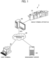
- FIG. 1 is a diagram illustrating an overall configuration of an image forming system, according to embodiments of the present disclosure.
- An image forming system 1 includes an image forming apparatus 10, a user terminal 30, a management server 40, and a digital front end (DFE) 50.
- DFE digital front end
- the image forming apparatus 10 is an apparatus to form an image, and is, for example, a color production printer, a laser printer, or an inkjet printer.
- the image forming apparatus 10 receives image data from the DFE 50 and prints the image on a sheet based on the received image data.
- the sheet is an example of a recording medium on which an image is formed.
- the user terminal 30 is a terminal that receives an operation from a user and instructs to print the image. Specifically, the user terminal 30 transmits print job data including image data to the DFE 50 or the management server 40. The user terminal 30 transmits information indicating a threshold in color stabilization processing to the DFE 50 in response to an operation of the user. In addition, the user terminal 30 receives display control by the DFE 50 and displays a screen indicating an execution status of the color stabilization processing.
- the management server 40 adds the print job data as a queue to a memory that stores the print job data waiting for printing in response to the receipt of the print job data from the user terminal 30.
- the management server 40 extracts print job data from the queue in the order in which the print job data is added to the queue or in accordance with a priority set appropriately. Then, the management server 40 transmits the print job data to the DFE 50.
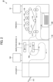
- the controller 1110 includes a central processing unit (CPU) 1101 that is a main part of a computer, a system memory (MEM-P) 1102, a north bridge (NB) 1103, a south bridge (SB) 1104, an application specific integrated circuit (ASIC) 1106, a local memory (MEM-C) 1107 that is a memory, a hard disk drive (HDD) controller 1108, and a hard disk (HD) 1109 that is a memory.
- CPU central processing unit
- MCM-P system memory
- NB north bridge
- SB south bridge
- ASIC application specific integrated circuit
- MEM-C local memory
- HDD hard disk drive
- HD hard disk
- the system control unit 501 includes a job information processing unit 551, a rasterized image processing unit 552, a control information storage unit 553, and a gradation correcting unit 554.
- the gradation correcting unit 554 corrects gradation of the image data converted by the rasterized image processing unit 552.
- the image forming unit of the printer 11 controls the printer section 1132 to form an image including the identification information of the second conveyance medium on the second conveyance medium. Accordingly, even when a plurality of defective printed sheets and the plurality of slip sheets corresponding to the defective printed sheets are ejected to an ejection device such as a sheet ejection tray, it is easy for a user to distinguish the slip sheets and confirm the defective printed sheets corresponding to each of the slip sheets.
- the mechanism control unit 306 controls an operation of a mechanism included in the inspection device 13 such as conveyance of the sheet.
- the defect determination unit 313 determines whether the printed image has a defect by comparing the difference image data with a predetermined threshold.
- the threshold is information (value) serving as a criterion for determining that the image has the defect.
- the defect determination unit 313 refers to the threshold and determines that the image has the defect if the difference image data has an area exceeding the threshold.
- the threshold is, for example, a value indicating that a difference (comparison result) between density values of each pixel included in the difference image data is equal to or greater than a predetermined density value, or a value indicating an area of a portion where pixels having a difference equal to or greater than the predetermined density value are continuous.
- the ejection setting unit 315 receives a setting of an interval for the ejection control of the slip sheet. Specifically, the ejection setting unit 315 receives an input of the above-described threshold. A specific example of a screen for receiving settings is described below.
- the value of the item "SHEET ID” is a numerical value to identify a sheet. When the duplex printing is performed, two “PAGE IDs” are given to the same sheet ID. The value of the item “SHEET ID” is incremented by one for process of each page starting from activation of the power source. A numerical value is set in the item "SHEET ID" when printing is executed.
- the value of the item "COPY ID” is a numerical value to identify a unit of copy and is incremented by one for output of each copy starting from activation of the power source. A numerical value is set in the item "COPY ID" when printing is executed.
- the value of the item "JOB ID” is a numerical value to identify the print job unit and is incremented by one for output of each job starting from activation of the power source. A numerical value is set in the item "JOB ID" when printing is executed.
- the value of the item "SHEET TYPE” is a value indicating the type of sheets.
- the value of the item “SHEET SIZE” is a value indicating the size of the sheets. Note that a sheet to be printed and used as a slip sheet is selectable, depending on the settings, between a sheet used in the print job in which the defect was detected or a sheet stacked on a designated sheet feeding tray. By using a sheet used in the print job for printing an image on the slip sheet, time-consuming process such as readjustment of the fixing temperature does not need to be performed, and the processing time is shortened. Further, when a sheet to be printed and used as a slip sheet is a sheet stacked on the designated sheet feeding tray, an inexpensive sheet is used to be dedicated to the slip sheet, and the cost is reduced.
- the value of the item "JOB TYPE” is a value indicating whether the job is a target of defect detection, a non-target of defect detection, or a slip sheet for defect detection identification.
- the value of the item "JOB TYPE” is a value indicating a slip sheet for defect detection identification.
- the defect determination unit 313 does not execute processing.
- FIG. 9 is a diagram illustrating pattern information, according to embodiments of the present disclosure.
- the pattern information 902 is set in advance and stored in the storage unit 305 or in the control information storage unit 311 of the inspection device 13.
- the ejection control unit 314 determines a color pattern to be printed on the slip sheet with reference to the pattern information 902.
- the pattern information 902 includes items "PATTERN NUMBER” and "CONTENTS”.
- the control information storage unit 311 stores a pattern number indicating which pattern of the pattern information 902 is referred to by the ejection control unit 314.
- the initial value of the pattern number is zero when the power source is turned on.
- the ejection control unit 314 increments by one to a numerical value indicating the pattern number stored in the control information storage unit 311 each time a print job for a slip sheet is generated with reference to the pattern information 902.
- the numerical value is reset to zero when the numerical value exceeds the maximum value.
- the slip sheet print information 903 is information indicating a combination of colors to be printed on each slip sheet and includes "SLIP SHEET ID” and "CONTENTS” as items.
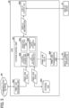
- FIG. 11 is a sequence diagram illustrating a flow of print processing without the slip sheet, according to embodiments of the present disclosure.
- the print job receiving unit 502 of the DFE 50 receives print job data from the user terminal 30 or the management server 40, the job information processing unit 551 generates job information (bibliographic information about the print job) for each page of the print job. Then, in step S101, the print job transmission unit 504 of the DFE 50 transmits job information (for example, page n) to the printer 11.
- job information for example, page n
- step S102 when the print job receiving unit 207 of the printer 11 receives the job information (page n), the job information processing unit 211 of the printer 11 performs processing such as addition of the numerical value indicating the page ID to update the received job information (page n) and transmits the updated job information to the inspection device 13 via the external I/F control unit 204.
- the rasterized image processing unit 552 of the DFE 50 performs processing of converting each page into the rasterized image data.
- the job information processing unit 551 and the rasterized image processing unit 552 of the DFE 50 perform processing in parallel, and the job information that completes processing first is transmitted to the printer 11 first.
- the DFE 50 generates and transmits job information for page n+1 and page n+2 before starting transmission of the rasterized image data (page n).
- steps S103 to S106 the printer 11 updates the received job information and transmits the updated job information to the inspection device 13.
- the rasterized image processing unit 552 of the DFE 50 generates rasterized image data (page n) corresponding to the job information (page n).
- the print job transmission unit 504 transmits the rasterized image (page n) to the printer 11.
- the rasterized image processing unit 212 of the printer 11 performs processing for the rasterized image data and transmits the processed rasterized image data to the inspection device 13.
- the master image generation unit 308 of the inspection device 13 generates master image data (page n) according to the job information (page n) and the rasterized image data (page n). Then, in accordance with the job information, the inspection device 13 associates the order of pages detected by the first inline sensor 131 and the second inline sensor 132 with the generated master image data and stores the association result in the storage unit 305.
- step S109 the image processing control unit 208, the printing control unit 209, and the mechanism control unit 206 of the printer 11 execute print processing in accordance with the job information (page n).
- the printed sheet (page n) is conveyed to the inspection device 13.
- steps S 110 to S115 the DFE 50 and the printer 11 perform processing on the rasterized image (pages n+1 and n+2) in the same way. Then, in steps S116 to S118, the print image reading unit 307 of the inspection device 13 acquires read image data (pages n, n+1, n+2) read by the first inline sensor 131 and the second inline sensor 132.
- the difference image generation unit 309 of the inspection device 13 generates difference image data indicating a difference between the master image data and the read image data for each page.
- the defect determination unit 313 determines whether the image includes any defect based on the generated difference image data and generates defect determination information.
- the ejection control unit 314 executes inspection processing including an inspection of whether to eject the slip sheet (second conveyance medium). Details of the inspection processing are described below.
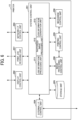
- FIG. 12 is a sequence diagram illustrating a flow of the print processing with the slip sheet, according to embodiments of the present disclosure.
- step S201 and step S202 are the same as step S101 and step S102, respectively, of the print processing without slip sheet illustrated in FIG. 11 .
- step S203 the defect determination unit 313 determines that the image includes a defect for the page n-5 on which print output has already been performed, and the ejection control unit 314 determines that the slip sheet is to be inserted by the inspection processing described below.
- the ejection control unit 314 of the inspection device 13 replaces the "sheet count value of the previously inserted slip sheet" stored in the control information storage unit 311 with the "sheet count value” of the sheet currently determined that the sheet has a defect.
- the "sheet count value of the previously inserted slip sheet” is the number of pages serving as a reference for determining whether the slip sheet is inserted.
- the inspection device 13 transmits the slip sheet print information 903 (page m) to the printer 11.
- the job information generation unit 213 of the printer 11 determines the timing of inserting the slip sheet and generates job information (page m).
- the timing of inserting the slip sheet may be a timing at which the slip sheet is inserted between page n and page n+1.
- the printer 11 transmits the generated job information (page m) to the inspection device 13.
- Step S206 and step S207 illustrated in FIG. 12 are the same as step S103 and step S104, respectively, of the print processing without slip sheet illustrated in FIG. 11 .
- steps S208 to S210 illustrated in FIG. 12 are the same as steps S107 to S109 of the print processing without a slip sheet as illustrated in FIG. 11 .
- step S211 at the timing of inserting a slip sheet (for example, between page n and page n+1), the image processing control unit 208, the printing control unit 209, and the mechanism control unit 206 of the printer 11 execute the print processing (printing of a slip sheet) according to the job information (page m).
- the slip sheet print job is not a job generated in the DFE 50
- the rasterized image data of the slip sheet is not transmitted from the DFE 50 to the printer 11.
- the slip sheet print information 903 for slip sheet printing has already been sent from the inspection device 13 to the printer 11.
- the slip sheet print information 903 may be configured to be transmitted from the inspection device 13 to the printer 11 via the DFE 50.
- Steps S212 to S214 and step S215 illustrated in FIG. 12 are the same as steps S110 to S 112 and step S116, respectively, of the print processing without a slip sheet illustrated in FIG. 11 .
- the inspection device 13 discards the read image data without performing the inspection processing.
- step S301 when the inspection processing starts, the ejection control unit 314 acquires the defect determination information.
- the defect determination information is information generated by the defect determination unit 313 and includes the information of defect determination result per printed page, the sheet count value, and the minimum value of the slip sheet insertion interval.
- step S302 the ejection control unit 314 determines the presence or absence of the defect with reference to the defect determination result included in the defect determination information. When it is determined that there is no defect (NO in step S302), the ejection control unit 314 ends the inspection processing.
- the ejection control unit 314 determines that the slip sheet is allowed to be inserted regardless of whether Equation 1 is satisfied or not.
- the ejection control unit 314 determines that the slip sheet is allowed to be inserted in the following two cases.
- the first case is when the sheet count value (the number of output pages of the defective sheet) of the current sheet determined to be defective is larger than the sheet count value of the slip sheet (the number of output pages of the slip sheet) at the previous insertion of the slip sheet and is greater than a predetermined insertion interval.
- the second case is when the slip sheet has not been inserted yet.
- the determination method is not limited to the above-described method.
- the following method may be employed as an alternative method.
- the ejection control unit 314 has determined that there is a defect in the image of the first conveyance medium, in a case where the ejection of the first conveyance medium determined to be defective is after the second conveyance medium is ejected and the value of the slip sheet insertion interval is equal to or smaller than the set interval, the second conveyance medium is not ejected even if the image of the first conveyance medium has a defect.
- the display control unit 302 displays information of the defective first conveyance medium ejected after the second conveyance medium previously ejected, in association with information of the second conveyance medium to be currently ejected.
- the sheet count value of the previously inserted slip sheet is stored in the control information storage unit 311 and is set to zero when the power of the image forming apparatus 10 is turned on.
- the ejection control unit 314 may wait until suitable timing for inserting the slip sheet and then insert the slip sheet again. That is, the timing at which the slip sheet is inserted is indicated by interrupting again the print job in which the slip sheet is not allowed to be inserted. Due to the above-described configuration, the slip sheet is allowed to be inserted each time the defect is found.
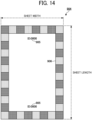
- FIG. 14 is a diagram illustrating the slip sheet, according to embodiments of the present disclosure.
- a slip sheet ID 905 is printed on the slip sheet 904, for example, at two upper and lower positions. Images of colors specified in the pattern information 902 are alternately printed as pattern images 906 on the outer circumferential portion of the slip sheet 904.
- the slip sheet ID and the pattern images 906 are an example of identification information to identify the slip sheet (second conveyance medium). Alternatively, the identification information may be a mark or a pattern.
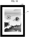
- FIG. 15 is a diagram illustrating a defect display screen, according to embodiments of the present disclosure.
- the display screen illustrated in FIG. 15 and the subsequent drawings are screens displayed on a display unit by the display control unit 302 transmitting screen information in response to a request received from the display unit such as an operation panel of an apparatus or a web browser of another apparatus.
- the display control unit 302 may display screen information on the display unit by bidirectional communication or push transmission.
- a defect display screen 907 is a screen displayed on the operation panel 133 of the inspection device 13 in order to display the detected defects.
- the defect display screen 907 includes a "JOB LIST” display area 908, a "DEFECT DETECTION PAGE LIST” display area 909, and a "DEFECT DETECTION IMAGE” display area 910.
- FIG. 16 is a diagram illustrating a job list, according to embodiments of the present disclosure.
- the job list displayed in the "JOB LIST" display area 908 includes items “INSPECTION PROCESSING START TIME”, “NUMBER OF COPIES OF JOB”, “NUMBER OF PAGES OF JOB”, and “NUMBER OF DEFECT-DETECTED PAGES OF JOB”.
- the job list may include identification information to identify the job, such as job names or job IDs, with which a plurality of jobs is confirmed and identified.
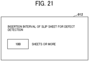
- FIG. 21 is a diagram illustrating a setting screen of an insertion interval of the slip sheet according to the first embodiment.
- the setting screen 912 is a screen via which the ejection setting unit 315 receives a setting of the insertion interval of the slip sheet.
- the setting screen 912 is a screen used by the display control unit 302 of the inspection device 13.
- the number of printed sheets to be output is input as insertion interval on the setting screen 912.
- the storage unit 305 stores information indicating the insertion interval of the slip sheet. Since the ejection setting unit 315 receives the setting, the printer 11 does not eject the slip sheet even if the defect is detected during the slip sheet insertion interval after the previous slip sheet is ejected.
- the insertion interval of the slip sheet may be set based on the number of outputs (printed sheets), an output time (period), or the number of jobs.
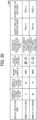
- FIG. 22 is a fourth diagram illustrating the defect detection page list according to the first embodiment.
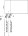
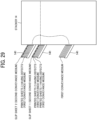
- FIG. 23 is a diagram illustrating an appearance of ejected sheets according to the first embodiment.
- the second conveyance medium such as the slip sheet and the defective first conveyance medium do not have to be adjacent to each other, and thus a physical portion such as the conveyance passage having the sufficient length as described above is not to be provided.
- the user is prompted to find the defect detected sheet by counting the number of sheets from the slip sheet found by the user. Since the number of sheets between the slip sheet and the defective sheet is relatively small in general, it is not difficult to count the number of sheets.
- the same slip sheet ID (for example, 0001) is included in a plurality of entries (for example, the first entry and the second entry in FIG. 24 ) in the defect detection page list.
- the above-described embodiments describe the examples in which the inspection device 13 generates the slip sheet print information 903 and the printer 11 generates print job data for the slip sheet based on the slip sheet print information 903.
- the inspection device 13 reduces the load of processing other than inspection and avoids a delay in the speed of inspection.
- the inspection device 13 may generate print job data for the slip sheet and transmit the print job data to the printer 11.
- the inspection device 13 generates image data for slip sheet printing in a format such as portable document format (PDF) and transmits the image data to the printer 11. Due to the above-described configuration, the printer 11 does not include a special mechanism for printing on a slip sheet, thus a system is easily introduced.
- PDF portable document format
- Processing circuitry includes a programmed processor, as a processor includes circuitry.
- a processing circuit also includes devices such as an application specific integrated circuit (ASIC), a digital signal processor (DSP), a field programmable gate array (FPGA), and conventional circuit components arranged to perform the recited functions.
- ASIC application specific integrated circuit
- DSP digital signal processor
- FPGA field programmable gate array
- the slip sheets and the printed sheets may be separately ejected to the plurality of sheet ejection trays 141.
- the slip sheet ejected to the upper sheet ejection tray 141 may indicate that the image that has the defect in the printed sheets of the lower sheet ejection tray 141.
- the present invention can be implemented in any convenient form, for example using dedicated hardware, or a mixture of dedicated hardware and software.
- the present invention may be implemented as computer software implemented by one or more networked processing apparatuses.
- the processing apparatuses include any suitably programmed apparatuses such as a general purpose computer, a personal digital assistant, a Wireless Application Protocol (WAP) or third-generation (3G)-compliant mobile telephone, and so on. Since the present invention can be implemented as software, each and every aspect of the present invention thus encompasses computer software implementable on a programmable device.
- the computer software can be provided to the programmable device using any conventional carrier medium (carrier means).
- the carrier medium includes a transient carrier medium such as an electrical, optical, microwave, acoustic or radio frequency signal carrying the computer code.
- transient medium is a Transmission Control Protocol/Internet Protocol (TCP/IP) signal carrying computer code over an IP network, such as the Internet.
- the carrier medium may also include a storage medium for storing processor readable code such as a floppy disk, a hard disk, a compact disc read-only memory (CD-ROM), a magnetic tape device, or a solid state memory device.
Landscapes
- Engineering & Computer Science (AREA)
- Theoretical Computer Science (AREA)
- Physics & Mathematics (AREA)
- General Physics & Mathematics (AREA)
- Human Computer Interaction (AREA)
- General Engineering & Computer Science (AREA)
- Microelectronics & Electronic Packaging (AREA)
- Multimedia (AREA)
- Signal Processing (AREA)
- Accessory Devices And Overall Control Thereof (AREA)
- Control Or Security For Electrophotography (AREA)
Claims (14)
- Bildverarbeitungssystem (1), umfassend:eine Bilderzeugungsvorrichtung (11), die dafür konfiguriert ist, auf der Grundlage von Druckinformationen ein Bild auf einem ersten Transportmedium auszubilden;eine Informationserfassungseinheit (131, 132, 307), die dafür konfiguriert ist, Informationen über das Bild zu erfassen, das auf dem ersten Transportmedium durch die Bilderzeugungsvorrichtung (11) ausgebildet wurde;eine Auswurfsteuerungseinheit (314), die dafür konfiguriert ist, in einem Fall, in dem das auf dem ersten Transportmedium ausgebildete Bild ein fehlerhaftes Bild ist, auf der Grundlage der durch die Informationserfassungseinheit (131, 132, 307) erfassten Informationen den Auswurf eines zweiten Transportmediums zu steuern;eine Auswurfvorrichtung (14, 141), die dafür konfiguriert ist, das erste Transportmedium und das zweite Transportmedium zu stapeln;eine Anzeigesteuerungseinheit (302), die dafür konfiguriert ist, die Anzeige von Identifizierungsinformationen zu steuern, die jedes aus einer Vielzahl von ersten Transportmedien mit fehlerhaften Bildern, die auf der Auswurfvorrichtung (14, 141) gestapelt sind, von einem entsprechenden aus einer Vielzahl von zweiten Transportmedien, die auf der Auswurfvorrichtung (14, 141) gestapelt sind, unterscheiden und ihm zuordnen; undeine Auswurfeinstellungseinheit (315), die dafür konfiguriert ist, eine Einstellung eines Intervalls des Auswurfs des zweiten Transportmediums zu empfangen,wobei die Auswurfsteuerungseinheit (314) dafür konfiguriert ist:als Antwort auf eine Bestimmung, dass das Bild auf dem ersten Transportmedium ein fehlerhaftes Bild ist, den Auswurf des zweiten Transportmediums in einem Fall anzuhalten, in dem das erste Transportmedium mit dem fehlerhaften Bild nach dem Auswurf des zweiten Transportmediums ausgeworfen werden soll und ein Einführungsintervall des zweiten Transportmediums gleich dem oder kleiner als das Intervall der durch die Auswurfeinstellungseinheit (315) empfangenen Einstellung ist; undzu veranlassen, dass das zweite Transportmedium nach der Bestimmung ausgeworfen wird, in einem Fall, in dem das erste Transportmedium mit dem fehlerhaften Bild nach dem Auswurf des zweiten Transportmediums ausgeworfen werden soll und das Einführungsintervall des zweiten Transportmediums größer ist als das Intervall der durch die Auswurfeinstellungseinheit (315) empfangenen Einstellung, undwobei die Anzeigesteuerungseinheit (302) dafür konfiguriert ist, die Anzeige von Informationen eines ersten Transportmediums mit einem fehlerhaften Bild, das nach dem vorherigen Auswurf eines zweiten Transportmediums ausgeworfen worden ist, in Verbindung mit Informationen des zweiten Transportmediums, das gerade ausgeworfen werden soll, zu steuern.
- Bildverarbeitungssystem (1) nach Anspruch 1, ferner eine Fehlerbestimmungseinheit (313) umfassend, die dafür konfiguriert ist, auf der Grundlage der durch die Informationserfassungseinheit (131, 132, 307) erfassten Informationen zu bestimmen, ob das auf dem ersten Transportmedium ausgebildete Bild ein fehlerhaftes Bild ist,
wobei die Auswurfsteuerungseinheit (314) dafür konfiguriert ist, als Antwort auf eine Bestimmung der Fehlerbestimmungseinheit (313), dass das auf dem ersten Transportmedium gebildete Bild ein fehlerhaftes Bild ist, den Auswurf des zweiten Transportmediums zu steuern. - Bildverarbeitungssystem (1) nach Anspruch 1 oder 2,
wobei die Anzeigesteuerungseinheit (302) dafür konfiguriert ist, die Anzeige von Informationen zu steuern, die eine Beziehung von Stapelpositionen zwischen jedem aus der Vielzahl von ersten Transportmedien mit fehlerhaften Bildern und dem entsprechenden aus der Vielzahl von zweiten Transportmedien angeben. - Bildverarbeitungssystem (1) nach einem der Ansprüche 1 bis 3,
wobei die Anzeigesteuerungseinheit (302) dafür konfiguriert ist, die Anzeige von Informationen zu steuern, die eine Beziehung von Positionen von einem aus der Vielzahl von ersten Transportmedien mit fehlerhaften Bildern und einem entsprechenden aus der Vielzahl von zweiten Transportmedien angeben, wobei die Informationen eine Anzahl von ersten Transportmedien einschließen, die zwischen dem einen aus der Vielzahl von ersten Transportmedien mit fehlerhaften Bildern und dem entsprechenden aus der Vielzahl von zweiten Transportmedien gestapelt sind. - Bildverarbeitungssystem (1) nach einem der Ansprüche 1 bis 4,
wobei die Bilderzeugungsvorrichtung (11) dafür konfiguriert ist, ein Bild auf einem Transportmedium auszubilden, das als das zweite Transportmedium erzeugt werden soll. - Bildverarbeitungssystem (1) nach Anspruch 5,
wobei die Bilderzeugungsvorrichtung (11) dafür konfiguriert ist, auf jedem aus der Vielzahl von zweiten Transportmedien, das der Vielzahl von ersten Transportmedien mit fehlerhaften Bildern zugeordnet ist, ein Identifizierungsbild auszubilden, das die Identifizierungsinformationen einschließt, und wobei die Identifizierungsinformationen Identifizierungsinformationen des zweiten Transportmediums einschließen, die angeben, dass jedes aus der Vielzahl von zweiten Transportmedien dem entsprechenden aus der Vielzahl von ersten Transportmedien mit fehlerhaften Bildern zugeordnet ist. - Bildverarbeitungssystem (1) nach Anspruch 6,
wobei das Identifizierungsbild, das die Identifizierungsinformationen des zweiten Transportmediums einschließt, auf dem zweiten Transportmedium so ausgebildet wird, dass das Identifizierungsbild von einer lateralen Seite der Auswurfvorrichtung (14, 141) aus sichtbar wird, wenn das zweite Transportmedium in die Auswurfvorrichtung (14, 141) ausgeworfen wird. - Bildverarbeitungssystem (1) nach Anspruch 6 oder 7,
wobei die Identifizierungsinformationen, die jedes aus der Vielzahl von ersten Transportmedien mit fehlerhaften Bildern auf der Auswurfvorrichtung (14, 141) von dem entsprechenden aus der Vielzahl von zweiten Transportmedien auf der Auswurfvorrichtung (14, 141) unterscheiden und ihm zuordnen, die Identifizierungsinformationen des zweiten Transportmediums, Informationen des ersten Transportmediums mit einem fehlerhaften Bild und Informationen einschließt, die eine Beziehung von Stapelpositionen zwischen dem ersten Transportmedium mit dem fehlerhaften Bild und dem zweiten Transportmedium angeben, die durch die Anzeigesteuereinheit (302) angezeigt werden. - Bildverarbeitungssystem (1) nach Anspruch 5,
wobei die Auswurfsteuerungseinheit (314) dafür konfiguriert ist, eine Kombination von Farben, die in einem auf dem zweiten Transportmedium auszubildenden Bild eingeschlossen sind, als die Identifizierungsinformationen des zweiten Transportmediums zu bestimmen. - Bildverarbeitungssystem (1) nach Anspruch 9,
wobei die Auswurfsteuerungseinheit (314) dafür konfiguriert ist, die Bilderzeugungsvorrichtung (11) anzuweisen, auf dem zweiten Transportmedium ein Bild auszubilden, das die Identifizierungsinformationen des zweiten Transportmediums einschließt. - Bildverarbeitungssystem (1) nach Anspruch 9 oder 10,
wobei die Anzeigesteuerungseinheit (302) dafür konfiguriert ist, die Anzeige einer Farbe zu steuern, die in dem auf dem zweiten Transportmedium ausgebildeten Bild eingeschlossen ist. - Bildverarbeitungssystem (1) nach einem der Ansprüche 1 bis 11,
wobei die Auswurfsteuerungseinheit (314) dafür konfiguriert ist, das Intervall des Auswurfs des zweiten Transportmediums anhand einer Anzahl von Ausgaben des ersten Transportmediums, einer Ausgabezeit des ersten Transportmediums oder einer Anzahl von Druckaufträgen einzustellen. - Inspektionsvorrichtung (13), umfassend:eine Informationserfassungseinheit (131, 132, 307), die dafür konfiguriert ist, Informationen über ein auf einem ersten Transportmedium ausgebildetes Bild zu erfassen;eine Auswurfsteuerungseinheit (314), die dafür konfiguriert ist, in einem Fall, in dem das auf dem ersten Transportmedium ausgebildete Bild ein fehlerhaftes Bild ist, auf der Grundlage der durch die Informationserfassungseinheit (131, 132, 307) erfassten Informationen zu veranlassen, dass ein zweites Transportmedium ausgeworfen wird;eine Anzeigesteuerungseinheit (302), die dafür konfiguriert ist, die Anzeige von Identifizierungsinformationen zu steuern, die jedes aus einer Vielzahl von ausgeworfenen ersten Transportmedien mit fehlerhaften Bildern von einem entsprechenden aus einer Vielzahl von ausgeworfenen zweiten Transportmedien unterscheiden und ihm zuordnen; undeine Auswurfeinstellungseinheit (315), die dafür konfiguriert ist, eine Einstellung eines Intervalls des Auswurfs des zweiten Transportmediums zu empfangen,wobei die Auswurfsteuerungseinheit (314) dafür konfiguriert ist:als Antwort auf eine Bestimmung, dass das Bild auf dem ersten Transportmedium ein fehlerhaftes Bild ist, den Auswurf des zweiten Transportmediums in einem Fall anzuhalten, in dem das erste Transportmedium mit dem fehlerhaften Bild nach dem Auswurf des zweiten Transportmediums ausgeworfen werden soll und ein Einführungsintervall des zweiten Transportmediums gleich dem oder kleiner als das Intervall der durch die Auswurfeinstellungseinheit (315) empfangenen Einstellung ist; undzu veranlassen, dass das zweite Transportmedium nach der Bestimmung ausgeworfen wird, in einem Fall, in dem das erste Transportmedium mit dem fehlerhaften Bild nach dem Auswurf des zweiten Transportmediums ausgeworfen werden soll und das Einführungsintervall des zweiten Transportmediums größer ist als das Intervall der durch die Auswurfeinstellungseinheit (315) empfangenen Einstellung, undwobei die Anzeigesteuerungseinheit (302) dafür konfiguriert ist, die Anzeige von Informationen eines ersten Transportmediums mit einem fehlerhaften Bild, das nach dem vorherigen Auswurf eines zweiten Transportmediums ausgeworfen worden ist, in Verbindung mit Informationen des zweiten Transportmediums, das gerade ausgeworfen werden soll, zu steuern.
- Inspektionsverfahren, das durch die Inspektionsvorrichtung nach Anspruch 13 auszuführen ist, wobei das Inspektionsverfahren Folgendes umfasst:Erfassen (S301) von Informationen über ein Bild, das auf dem ersten Transportmedium ausgebildet ist;Bestimmen (S302) des Vorliegens oder Nichtvorliegens eines Fehlers auf der Grundlage der durch das Erfassen erfassten Informationen;Auswerfen (S303) des zweiten Transportmediums in einem Fall, in dem das auf dem ersten Transportmedium ausgebildete Bild ein fehlerhaftes Bild ist, auf der Grundlage der durch das Erfassen erfassten Informationen, es sei denn, dass das Einführungsintervall des zweiten Transportmediums gleich dem oder kleiner als das Intervall der durch die Auswurfeinstellungseinheit (315) empfangenen Einstellung ist; undAnzeigen (S304) von Identifizierungsinformationen, die jedes aus einer Vielzahl von ausgeworfenen ersten Transportmedien mit fehlerhaften Bildern von einem entsprechenden aus einer Vielzahl von ausgeworfenen zweiten Transportmedien unterscheiden und zuordnen.
Applications Claiming Priority (1)
| Application Number | Priority Date | Filing Date | Title |
|---|---|---|---|
| JP2021046488A JP7647212B2 (ja) | 2021-03-19 | 2021-03-19 | 画像形成システム、検査装置、検査方法およびプログラム |
Publications (2)
| Publication Number | Publication Date |
|---|---|
| EP4060413A1 EP4060413A1 (de) | 2022-09-21 |
| EP4060413B1 true EP4060413B1 (de) | 2024-07-10 |
Family
ID=79164497
Family Applications (1)
| Application Number | Title | Priority Date | Filing Date |
|---|---|---|---|
| EP21218394.1A Active EP4060413B1 (de) | 2021-03-19 | 2021-12-30 | Bilderzeugungssystem, inspektionsvorrichtung und inspektionsverfahren |
Country Status (4)
| Country | Link |
|---|---|
| US (1) | US11645016B2 (de) |
| EP (1) | EP4060413B1 (de) |
| JP (1) | JP7647212B2 (de) |
| CN (1) | CN115118831B (de) |
Families Citing this family (2)
| Publication number | Priority date | Publication date | Assignee | Title |
|---|---|---|---|---|
| JP7583640B2 (ja) * | 2021-02-22 | 2024-11-14 | キヤノン株式会社 | 印刷システム、印刷装置と情報処理装置及びそれらの制御方法、並びにプログラム |
| US20250157017A1 (en) * | 2023-11-13 | 2025-05-15 | Ricoh Company, Ltd. | Inspection production control mechanism |
Family Cites Families (22)
| Publication number | Priority date | Publication date | Assignee | Title |
|---|---|---|---|---|
| JPH0575248U (ja) * | 1992-03-23 | 1993-10-15 | 株式会社ニコン | プリントペーパ識別装置 |
| JP2003167397A (ja) * | 2001-11-30 | 2003-06-13 | Canon Inc | 画像形成システムおよび画像形成システムの制御方法およびプログラム及び記憶媒体 |
| JP2005205747A (ja) * | 2004-01-23 | 2005-08-04 | Fuji Xerox Co Ltd | 画像形成装置並びにその制御装置、制御方法及び制御プログラム |
| US7546055B2 (en) * | 2006-03-09 | 2009-06-09 | Kabushiki Kaisha Toshiba | Image forming apparatus |
| JP4813340B2 (ja) * | 2006-12-13 | 2011-11-09 | 株式会社東芝 | 画像形成装置、画像形成方法、及び画像形成プログラム |
| JP2010002463A (ja) * | 2008-06-18 | 2010-01-07 | Konica Minolta Business Technologies Inc | 画像形成装置 |
| JP5233490B2 (ja) * | 2008-08-05 | 2013-07-10 | 富士ゼロックス株式会社 | 画像形成装置 |
| JP5832140B2 (ja) * | 2011-05-12 | 2015-12-16 | キヤノン株式会社 | 印刷装置、印刷方法、及びプログラム |
| JP2013024564A (ja) | 2011-07-14 | 2013-02-04 | Ricoh Co Ltd | 画像検査装置、画像検査システム及び画像検査方法 |
| JP6015189B2 (ja) | 2011-08-16 | 2016-10-26 | 株式会社リコー | 画像検査装置、画像形成装置、画像検査方法及び画像形成システム |
| JP2013198055A (ja) | 2012-03-22 | 2013-09-30 | Ricoh Co Ltd | 画像読取装置及び画像読取装置の制御方法 |
| JP5867216B2 (ja) | 2012-03-22 | 2016-02-24 | 株式会社リコー | 画像検査方法、画像検査装置、画像検査装置の制御プログラム |
| JP6241120B2 (ja) | 2012-09-14 | 2017-12-06 | 株式会社リコー | 画像検査装置、画像検査方法及び画像検査装置の制御プログラム |
| JP6357786B2 (ja) | 2013-03-15 | 2018-07-18 | 株式会社リコー | 画像検査装置、画像検査システム及び画像検査方法 |
| JP5884760B2 (ja) | 2013-03-22 | 2016-03-15 | 富士ゼロックス株式会社 | 画像検査システムおよび画像検査装置 |
| JP2015194484A (ja) | 2014-03-18 | 2015-11-05 | 株式会社リコー | 画像検査装置、画像形成システム及び画像検査プログラム |
| JP2017034298A (ja) * | 2015-07-28 | 2017-02-09 | 株式会社リコー | 検査システム、印刷装置及び印刷物位置報知方法 |
| JP6699430B2 (ja) * | 2016-07-27 | 2020-05-27 | 富士ゼロックス株式会社 | 画像処理装置、画像処理プログラム、印刷装置 |
| JP2018089869A (ja) * | 2016-12-05 | 2018-06-14 | キヤノン株式会社 | 画像形成装置 |
| JP6950479B2 (ja) * | 2017-11-15 | 2021-10-13 | コニカミノルタ株式会社 | 画像形成装置 |
| JP7222268B2 (ja) * | 2019-02-28 | 2023-02-15 | ブラザー工業株式会社 | 画像記録装置 |
| JP7309416B2 (ja) * | 2019-03-29 | 2023-07-18 | キヤノン株式会社 | 画像形成装置、画像形成方法、及び、プログラム |
-
2021
- 2021-03-19 JP JP2021046488A patent/JP7647212B2/ja active Active
- 2021-12-30 EP EP21218394.1A patent/EP4060413B1/de active Active
-
2022
- 2022-01-10 US US17/571,539 patent/US11645016B2/en active Active
- 2022-03-10 CN CN202210234424.9A patent/CN115118831B/zh active Active
Also Published As
| Publication number | Publication date |
|---|---|
| US20220300219A1 (en) | 2022-09-22 |
| CN115118831A (zh) | 2022-09-27 |
| JP2022145188A (ja) | 2022-10-03 |
| EP4060413A1 (de) | 2022-09-21 |
| CN115118831B (zh) | 2024-06-14 |
| US11645016B2 (en) | 2023-05-09 |
| JP7647212B2 (ja) | 2025-03-18 |
Similar Documents
| Publication | Publication Date | Title |
|---|---|---|
| EP4060416A1 (de) | Bilderzeugungsvorrichtung | |
| US20230083271A1 (en) | Inspection device, method of determining non-inspection-target area, and storage medium | |
| EP4060413B1 (de) | Bilderzeugungssystem, inspektionsvorrichtung und inspektionsverfahren | |
| JP2016118446A (ja) | 情報処理装置、欠陥送信方法及びプログラム | |
| US11089181B2 (en) | Image forming apparatus, system and program product acquiring color information of image printed on first side before printing on second side of print medium | |
| JP2008265205A (ja) | 画像形成装置、プログラム、及び画像形成方法 | |
| EP4060417B1 (de) | Inspektionsvorrichtung, bilderzeugungssystem, inspektionsverfahren und trägermedium | |
| US12272081B2 (en) | Inspection apparatus, image forming system, misalignment measurement method and storage medium | |
| US11720771B2 (en) | Image forming system for generating print image data of an image to include identification information in a margin area outside the image, image forming method, and storage medium | |
| EP4060415B1 (de) | Bilderzeugungssystem, inspektionsvorrichtung und inspektionsverfahren | |
| JP7367477B2 (ja) | 画像形成装置、制御方法、およびプログラム | |
| US11853823B2 (en) | Image forming system, method of printing identification information, and storage medium | |
| US20250245459A1 (en) | Image forming apparatus, image forming method, and non-transitory recording medium | |
| US20260025471A1 (en) | Inspection system, inspection method, and non-transitory recording medium | |
| US20200364007A1 (en) | Image forming device, control method of image forming device, and program | |
| JP4888024B2 (ja) | 画像形成装置 | |
| JP2013211708A (ja) | 画像形成装置 |
Legal Events
| Date | Code | Title | Description |
|---|---|---|---|
| PUAI | Public reference made under article 153(3) epc to a published international application that has entered the european phase |
Free format text: ORIGINAL CODE: 0009012 |
|
| STAA | Information on the status of an ep patent application or granted ep patent |
Free format text: STATUS: REQUEST FOR EXAMINATION WAS MADE |
|
| 17P | Request for examination filed |
Effective date: 20211230 |
|
| AK | Designated contracting states |
Kind code of ref document: A1 Designated state(s): AL AT BE BG CH CY CZ DE DK EE ES FI FR GB GR HR HU IE IS IT LI LT LU LV MC MK MT NL NO PL PT RO RS SE SI SK SM TR |
|
| GRAP | Despatch of communication of intention to grant a patent |
Free format text: ORIGINAL CODE: EPIDOSNIGR1 |
|
| STAA | Information on the status of an ep patent application or granted ep patent |
Free format text: STATUS: GRANT OF PATENT IS INTENDED |
|
| INTG | Intention to grant announced |
Effective date: 20240202 |
|
| P01 | Opt-out of the competence of the unified patent court (upc) registered |
Effective date: 20240402 |
|
| GRAS | Grant fee paid |
Free format text: ORIGINAL CODE: EPIDOSNIGR3 |
|
| GRAA | (expected) grant |
Free format text: ORIGINAL CODE: 0009210 |
|
| STAA | Information on the status of an ep patent application or granted ep patent |
Free format text: STATUS: THE PATENT HAS BEEN GRANTED |
|
| AK | Designated contracting states |
Kind code of ref document: B1 Designated state(s): AL AT BE BG CH CY CZ DE DK EE ES FI FR GB GR HR HU IE IS IT LI LT LU LV MC MK MT NL NO PL PT RO RS SE SI SK SM TR |
|
| REG | Reference to a national code |
Ref country code: CH Ref legal event code: EP |
|
| REG | Reference to a national code |
Ref country code: DE Ref legal event code: R096 Ref document number: 602021015437 Country of ref document: DE |
|
| REG | Reference to a national code |
Ref country code: LT Ref legal event code: MG9D |
|
| REG | Reference to a national code |
Ref country code: NL Ref legal event code: MP Effective date: 20240710 |
|
| PG25 | Lapsed in a contracting state [announced via postgrant information from national office to epo] |
Ref country code: PT Free format text: LAPSE BECAUSE OF FAILURE TO SUBMIT A TRANSLATION OF THE DESCRIPTION OR TO PAY THE FEE WITHIN THE PRESCRIBED TIME-LIMIT Effective date: 20241111 |
|
| REG | Reference to a national code |
Ref country code: AT Ref legal event code: MK05 Ref document number: 1702574 Country of ref document: AT Kind code of ref document: T Effective date: 20240710 |
|
| PG25 | Lapsed in a contracting state [announced via postgrant information from national office to epo] |
Ref country code: NL Free format text: LAPSE BECAUSE OF FAILURE TO SUBMIT A TRANSLATION OF THE DESCRIPTION OR TO PAY THE FEE WITHIN THE PRESCRIBED TIME-LIMIT Effective date: 20240710 |
|
| PG25 | Lapsed in a contracting state [announced via postgrant information from national office to epo] |
Ref country code: PT Free format text: LAPSE BECAUSE OF FAILURE TO SUBMIT A TRANSLATION OF THE DESCRIPTION OR TO PAY THE FEE WITHIN THE PRESCRIBED TIME-LIMIT Effective date: 20241111 Ref country code: NL Free format text: LAPSE BECAUSE OF FAILURE TO SUBMIT A TRANSLATION OF THE DESCRIPTION OR TO PAY THE FEE WITHIN THE PRESCRIBED TIME-LIMIT Effective date: 20240710 |
|
| PG25 | Lapsed in a contracting state [announced via postgrant information from national office to epo] |
Ref country code: NO Free format text: LAPSE BECAUSE OF FAILURE TO SUBMIT A TRANSLATION OF THE DESCRIPTION OR TO PAY THE FEE WITHIN THE PRESCRIBED TIME-LIMIT Effective date: 20241010 |
|
| PG25 | Lapsed in a contracting state [announced via postgrant information from national office to epo] |
Ref country code: GR Free format text: LAPSE BECAUSE OF FAILURE TO SUBMIT A TRANSLATION OF THE DESCRIPTION OR TO PAY THE FEE WITHIN THE PRESCRIBED TIME-LIMIT Effective date: 20241011 Ref country code: FI Free format text: LAPSE BECAUSE OF FAILURE TO SUBMIT A TRANSLATION OF THE DESCRIPTION OR TO PAY THE FEE WITHIN THE PRESCRIBED TIME-LIMIT Effective date: 20240710 Ref country code: PL Free format text: LAPSE BECAUSE OF FAILURE TO SUBMIT A TRANSLATION OF THE DESCRIPTION OR TO PAY THE FEE WITHIN THE PRESCRIBED TIME-LIMIT Effective date: 20240710 |
|
| PG25 | Lapsed in a contracting state [announced via postgrant information from national office to epo] |
Ref country code: BG Free format text: LAPSE BECAUSE OF FAILURE TO SUBMIT A TRANSLATION OF THE DESCRIPTION OR TO PAY THE FEE WITHIN THE PRESCRIBED TIME-LIMIT Effective date: 20240710 |
|
| PG25 | Lapsed in a contracting state [announced via postgrant information from national office to epo] |
Ref country code: LV Free format text: LAPSE BECAUSE OF FAILURE TO SUBMIT A TRANSLATION OF THE DESCRIPTION OR TO PAY THE FEE WITHIN THE PRESCRIBED TIME-LIMIT Effective date: 20240710 |
|
| PG25 | Lapsed in a contracting state [announced via postgrant information from national office to epo] |
Ref country code: AT Free format text: LAPSE BECAUSE OF FAILURE TO SUBMIT A TRANSLATION OF THE DESCRIPTION OR TO PAY THE FEE WITHIN THE PRESCRIBED TIME-LIMIT Effective date: 20240710 Ref country code: IS Free format text: LAPSE BECAUSE OF FAILURE TO SUBMIT A TRANSLATION OF THE DESCRIPTION OR TO PAY THE FEE WITHIN THE PRESCRIBED TIME-LIMIT Effective date: 20241110 |
|
| PG25 | Lapsed in a contracting state [announced via postgrant information from national office to epo] |
Ref country code: HR Free format text: LAPSE BECAUSE OF FAILURE TO SUBMIT A TRANSLATION OF THE DESCRIPTION OR TO PAY THE FEE WITHIN THE PRESCRIBED TIME-LIMIT Effective date: 20240710 |
|
| PG25 | Lapsed in a contracting state [announced via postgrant information from national office to epo] |
Ref country code: ES Free format text: LAPSE BECAUSE OF FAILURE TO SUBMIT A TRANSLATION OF THE DESCRIPTION OR TO PAY THE FEE WITHIN THE PRESCRIBED TIME-LIMIT Effective date: 20240710 Ref country code: RS Free format text: LAPSE BECAUSE OF FAILURE TO SUBMIT A TRANSLATION OF THE DESCRIPTION OR TO PAY THE FEE WITHIN THE PRESCRIBED TIME-LIMIT Effective date: 20241010 |
|
| PG25 | Lapsed in a contracting state [announced via postgrant information from national office to epo] |
Ref country code: RS Free format text: LAPSE BECAUSE OF FAILURE TO SUBMIT A TRANSLATION OF THE DESCRIPTION OR TO PAY THE FEE WITHIN THE PRESCRIBED TIME-LIMIT Effective date: 20241010 Ref country code: PL Free format text: LAPSE BECAUSE OF FAILURE TO SUBMIT A TRANSLATION OF THE DESCRIPTION OR TO PAY THE FEE WITHIN THE PRESCRIBED TIME-LIMIT Effective date: 20240710 Ref country code: NO Free format text: LAPSE BECAUSE OF FAILURE TO SUBMIT A TRANSLATION OF THE DESCRIPTION OR TO PAY THE FEE WITHIN THE PRESCRIBED TIME-LIMIT Effective date: 20241010 Ref country code: LV Free format text: LAPSE BECAUSE OF FAILURE TO SUBMIT A TRANSLATION OF THE DESCRIPTION OR TO PAY THE FEE WITHIN THE PRESCRIBED TIME-LIMIT Effective date: 20240710 Ref country code: IS Free format text: LAPSE BECAUSE OF FAILURE TO SUBMIT A TRANSLATION OF THE DESCRIPTION OR TO PAY THE FEE WITHIN THE PRESCRIBED TIME-LIMIT Effective date: 20241110 Ref country code: HR Free format text: LAPSE BECAUSE OF FAILURE TO SUBMIT A TRANSLATION OF THE DESCRIPTION OR TO PAY THE FEE WITHIN THE PRESCRIBED TIME-LIMIT Effective date: 20240710 Ref country code: GR Free format text: LAPSE BECAUSE OF FAILURE TO SUBMIT A TRANSLATION OF THE DESCRIPTION OR TO PAY THE FEE WITHIN THE PRESCRIBED TIME-LIMIT Effective date: 20241011 Ref country code: FI Free format text: LAPSE BECAUSE OF FAILURE TO SUBMIT A TRANSLATION OF THE DESCRIPTION OR TO PAY THE FEE WITHIN THE PRESCRIBED TIME-LIMIT Effective date: 20240710 Ref country code: ES Free format text: LAPSE BECAUSE OF FAILURE TO SUBMIT A TRANSLATION OF THE DESCRIPTION OR TO PAY THE FEE WITHIN THE PRESCRIBED TIME-LIMIT Effective date: 20240710 Ref country code: BG Free format text: LAPSE BECAUSE OF FAILURE TO SUBMIT A TRANSLATION OF THE DESCRIPTION OR TO PAY THE FEE WITHIN THE PRESCRIBED TIME-LIMIT Effective date: 20240710 Ref country code: AT Free format text: LAPSE BECAUSE OF FAILURE TO SUBMIT A TRANSLATION OF THE DESCRIPTION OR TO PAY THE FEE WITHIN THE PRESCRIBED TIME-LIMIT Effective date: 20240710 |
|
| REG | Reference to a national code |
Ref country code: DE Ref legal event code: R097 Ref document number: 602021015437 Country of ref document: DE |
|
| PG25 | Lapsed in a contracting state [announced via postgrant information from national office to epo] |
Ref country code: DK Free format text: LAPSE BECAUSE OF FAILURE TO SUBMIT A TRANSLATION OF THE DESCRIPTION OR TO PAY THE FEE WITHIN THE PRESCRIBED TIME-LIMIT Effective date: 20240710 Ref country code: SM Free format text: LAPSE BECAUSE OF FAILURE TO SUBMIT A TRANSLATION OF THE DESCRIPTION OR TO PAY THE FEE WITHIN THE PRESCRIBED TIME-LIMIT Effective date: 20240710 Ref country code: RO Free format text: LAPSE BECAUSE OF FAILURE TO SUBMIT A TRANSLATION OF THE DESCRIPTION OR TO PAY THE FEE WITHIN THE PRESCRIBED TIME-LIMIT Effective date: 20240710 |
|
| PG25 | Lapsed in a contracting state [announced via postgrant information from national office to epo] |
Ref country code: EE Free format text: LAPSE BECAUSE OF FAILURE TO SUBMIT A TRANSLATION OF THE DESCRIPTION OR TO PAY THE FEE WITHIN THE PRESCRIBED TIME-LIMIT Effective date: 20240710 |
|
| PG25 | Lapsed in a contracting state [announced via postgrant information from national office to epo] |
Ref country code: CZ Free format text: LAPSE BECAUSE OF FAILURE TO SUBMIT A TRANSLATION OF THE DESCRIPTION OR TO PAY THE FEE WITHIN THE PRESCRIBED TIME-LIMIT Effective date: 20240710 |
|
| PG25 | Lapsed in a contracting state [announced via postgrant information from national office to epo] |
Ref country code: SK Free format text: LAPSE BECAUSE OF FAILURE TO SUBMIT A TRANSLATION OF THE DESCRIPTION OR TO PAY THE FEE WITHIN THE PRESCRIBED TIME-LIMIT Effective date: 20240710 Ref country code: IT Free format text: LAPSE BECAUSE OF FAILURE TO SUBMIT A TRANSLATION OF THE DESCRIPTION OR TO PAY THE FEE WITHIN THE PRESCRIBED TIME-LIMIT Effective date: 20240710 |
|
| PLBE | No opposition filed within time limit |
Free format text: ORIGINAL CODE: 0009261 |
|
| STAA | Information on the status of an ep patent application or granted ep patent |
Free format text: STATUS: NO OPPOSITION FILED WITHIN TIME LIMIT |
|
| 26N | No opposition filed |
Effective date: 20250411 |
|
| PG25 | Lapsed in a contracting state [announced via postgrant information from national office to epo] |
Ref country code: MC Free format text: LAPSE BECAUSE OF FAILURE TO SUBMIT A TRANSLATION OF THE DESCRIPTION OR TO PAY THE FEE WITHIN THE PRESCRIBED TIME-LIMIT Effective date: 20240710 |
|
| REG | Reference to a national code |
Ref country code: CH Ref legal event code: PL |
|
| PG25 | Lapsed in a contracting state [announced via postgrant information from national office to epo] |
Ref country code: LU Free format text: LAPSE BECAUSE OF NON-PAYMENT OF DUE FEES Effective date: 20241230 |
|
| PG25 | Lapsed in a contracting state [announced via postgrant information from national office to epo] |
Ref country code: SE Free format text: LAPSE BECAUSE OF FAILURE TO SUBMIT A TRANSLATION OF THE DESCRIPTION OR TO PAY THE FEE WITHIN THE PRESCRIBED TIME-LIMIT Effective date: 20240710 |
|
| REG | Reference to a national code |
Ref country code: BE Ref legal event code: MM Effective date: 20241231 |
|
| PG25 | Lapsed in a contracting state [announced via postgrant information from national office to epo] |
Ref country code: BE Free format text: LAPSE BECAUSE OF NON-PAYMENT OF DUE FEES Effective date: 20241231 |
|
| PG25 | Lapsed in a contracting state [announced via postgrant information from national office to epo] |
Ref country code: CH Free format text: LAPSE BECAUSE OF NON-PAYMENT OF DUE FEES Effective date: 20241231 |
|
| PG25 | Lapsed in a contracting state [announced via postgrant information from national office to epo] |
Ref country code: IE Free format text: LAPSE BECAUSE OF NON-PAYMENT OF DUE FEES Effective date: 20241230 |
|
| PGFP | Annual fee paid to national office [announced via postgrant information from national office to epo] |
Ref country code: DE Payment date: 20251211 Year of fee payment: 5 |
|
| PGFP | Annual fee paid to national office [announced via postgrant information from national office to epo] |
Ref country code: GB Payment date: 20251219 Year of fee payment: 5 |
|
| PGFP | Annual fee paid to national office [announced via postgrant information from national office to epo] |
Ref country code: FR Payment date: 20251229 Year of fee payment: 5 |