EP4060352A1 - Automatisches triggertyp-identifikationsverfahren und -vorrichtung und oszilloskop - Google Patents
Automatisches triggertyp-identifikationsverfahren und -vorrichtung und oszilloskop Download PDFInfo
- Publication number
- EP4060352A1 EP4060352A1 EP20887962.7A EP20887962A EP4060352A1 EP 4060352 A1 EP4060352 A1 EP 4060352A1 EP 20887962 A EP20887962 A EP 20887962A EP 4060352 A1 EP4060352 A1 EP 4060352A1
- Authority
- EP
- European Patent Office
- Prior art keywords
- signal
- triggered signal
- triggered
- characteristic parameter
- edge slope
- Prior art date
- Legal status (The legal status is an assumption and is not a legal conclusion. Google has not performed a legal analysis and makes no representation as to the accuracy of the status listed.)
- Pending
Links
Images


Classifications
-
- G—PHYSICS
- G01—MEASURING; TESTING
- G01R—MEASURING ELECTRIC VARIABLES; MEASURING MAGNETIC VARIABLES
- G01R13/00—Arrangements for displaying electric variables or waveforms
- G01R13/02—Arrangements for displaying electric variables or waveforms for displaying measured electric variables in digital form
- G01R13/0218—Circuits therefor
- G01R13/0254—Circuits therefor for triggering, synchronisation
Definitions
- the present application relates to the field of oscilloscope technologies, for example, an automatic trigger type identification method and device and an oscilloscope.
- the trigger of the oscilloscope refers to that when a certain waveform in the sampled data stream of the oscilloscope satisfies a condition set by the user according to requirements, the oscilloscope captures the waveform and adjacent parts of the waveform in real time.
- the condition set by the user is referred to as a trigger condition.
- the effect of the trigger is to capture the event of interest and display the waveform stably.
- the oscilloscope has various trigger types, and the parameter setting process is also complicated, which makes users who are unfamiliar with the oscilloscope or have no operation experience unable to reasonably select the trigger types according to characteristics of signals, resulting in more time-consuming signal debugging.
- the AUTO function refers to that the user manually presses an "auto" key of the oscilloscope, then the oscilloscope automatically adjusts the horizontal scale and the vertical scale according to the amplitude and frequency of a current signal so that the waveform can spread the whole screen as far as possible in the vertical direction and display one or two periods in the horizontal direction, and at the same time, sets the trigger type as the edge trigger, finally achieving a relatively good observation effect.
- the more suitable trigger type is not the edge trigger, however, the AUTO function in the related art can only identify and configure the trigger type of the edge trigger. Therefore, a new trigger type identification method is urgently needed.
- the present application provides an automatic trigger type identification method and device and an oscilloscope, through which a trigger type capable of stably triggering a to-be-triggered signal can be obtained according to a preset rule for user selection or automatic selection for trigger.
- the present application provides an automatic trigger type identification method.
- the method includes steps described below.
- a to-be-triggered signal is acquired.
- Characteristic parameter data of the to-be-triggered signal is calculated in real time, where the characteristic parameter data includes at least one of bus protocol matching information or variation information of at least one characteristic parameter.
- a trigger type capable of stably triggering the to-be-triggered signal is determined according to the characteristic parameter data.
- the present application further provides an automatic trigger type identification device.
- the device includes an acquisition unit, a characteristic extraction unit and a trigger type analysis unit.
- the acquisition unit is configured to acquire a to-be-triggered signal.
- the characteristic extraction unit is configured to calculate characteristic parameter data of the to-be-triggered signal in real time, where the characteristic parameter data includes at least one of bus protocol matching information or variation information of at least one characteristic parameter.
- the trigger type analysis unit is configured to determine a trigger type capable of stably triggering the to-be-triggered signal according to the characteristic parameter data.
- the present application provides an oscilloscope including a memory and a processor, where the memory is configured to store a program, and the processor is configured to execute the program to implement any automatic trigger type identification method of the first aspect.
- waveform data sampled by an analog to digital converter is analyzed in real time, that is, characteristic parameter data, of a to-be-triggered signal, such as at least one of bus protocol matching information or variation information of at least one characteristic parameter, is obtained by analysis and calculation, and then a trigger type capable of stably triggering the to-be-triggered signal is determined according to the characteristic parameter data of the to-be-triggered signal obtained by analysis, so that the to-be-triggered signal can be better observed and tested.
- ADC analog to digital converter
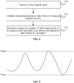
- FIG. 1 is a flowchart of an automatic trigger type identification method according to an embodiment of the present application.
- the method includes steps S11 to S13.
- step S11 a to-be-triggered signal is acquired.
- Step S11 is executed to acquire the to-be-triggered signal output by the ADC of the oscilloscope.
- An analog front-end of the oscilloscope performs amplification or attenuation preprocessing on an original analog signal, and then the analog signal is converted into a digital signal to output through acquisition, quantization and encoding by the high-speed ADC.
- step S12 characteristic parameter data of the to-be-triggered signal is calculated in real time.
- the characteristic parameter data includes at least one of bus protocol matching information or variation information of at least one characteristic parameter.
- the variation information of the characteristic parameter includes, but is not limited to, peak-to-peak value variation information, edge slope variation information, frequency variation information, pulse width variation information and envelope variation information.
- the line of all maximum values and the line of all minimum values of the to-be-triggered signal is an envelope signal of the to-be-triggered signal.
- the bus protocol matching information is the information identified, by the analysis of information such as a data format of the to-be-triggered signal, to determine which type of bus protocol is matched.
- the to-be-triggered signal matching the bus protocol represents that the to-be-triggered signal is transmitted by the bus corresponding to the bus protocol.
- the characteristic parameter data of the to-be-triggered signal is analyzed and calculated so as to subsequently select a relatively suitable trigger type for trigger.
- a trigger type capable of stably triggering the to-be-triggered signal is determined according to the characteristic parameter data obtained by calculation. Multiple trigger types capable of stably triggering the to-be-triggered signal may be determined. After the multiple trigger types capable of stably triggering the to-be-triggered signal are determined, all the determined trigger types capable of stably triggering the to-be-triggered signal may be directly displayed for the user to select. Alternatively, a sequential order of various trigger types is preset, so that after the multiple trigger types capable of stably triggering the to-be-triggered signal are determined, the trigger type ranking first is selected to trigger the to-be-triggered signal from all the trigger types capable of stably triggering the to-be-triggered signal according to the sequential order of the various trigger types.
- the sequential order of the various trigger types may be a pre-designed fixed order which cannot be modified by the user; or a configuration system may be set for the user to set the sequential order of the various trigger types; or the determined trigger types may be automatically ordered according to their trigger effects based on the features of the to-be-triggered signal.
- multiple trigger types are determined, and after the multiple trigger types capable of stably triggering the to-be-triggered signal are determined according to the characteristic parameter data, the method further includes the step described below.
- At least one trigger type of the multiple trigger types capable of stably triggering the to-be-triggered signal is displayed.
- multiple trigger types are determined, and after the multiple trigger types capable of stably triggering the to-be-triggered signal are determined according to the characteristic parameter data, the method further includes the step described below.
- One trigger type is selected from the multiple trigger types to trigger the to-be-triggered signal.
- At least one piece of characteristic parameter data of the to-be-triggered signal may be calculated.
- the characteristic parameter data of the to-be-triggered signal obtained by calculation includes at least one of bus protocol matching information or variation information of at least one characteristic parameter.
- the variation information of the at least one characteristic parameter includes at least one of peak-to-peak value variation information, edge slope variation information, frequency variation information, pulse width variation information or envelope variation information.
- step A11 an edge slope of the to-be-triggered signal is detected.
- the edge slope includes a rising edge slope and a falling edge slope.
- the process of detecting the edge slope of the to-be-triggered signal includes steps described below.
- step A111 a maximum value and a minimum value of the to-be-triggered signal are detected in real time.
- the currently recorded maximum value and minimum value that is, the maximum value and the minimum value of the current to-be-triggered signal, are determined and respectively denoted as V max and Vmin.
- FIG. 2 is a diagram showing the maximum value V max and the minimum value Vmin of the to-be-triggered signal. A reasonable threshold and vertical scale may be set through the V max and the Vmin.
- the current maximum value and minimum value are latched, and the latched maximum value and minimum value are respectively compared with a newly identified maximum value and minimum value.
- the latched maximum value is replaced with the newly identified maximum value; in a case where the difference between the latched minimum value and the newly identified minimum value is greater than a preset second threshold, the latched minimum value is replaced with the newly identified minimum value.
- the first preset time may be 100ms or even 1s.
- the current latched values are determined as the maximum value and the minimum value of the to-be-triggered signal.
- the sampling is real-time and uninterrupted in practice, and therefore the detection of the maximum value and the minimum value of the to-be-triggered signal is also real-time and uninterrupted.
- the process of calculating the peak-to-peak value variation information is as follows. A maximum value and a minimum value of the peak-to-peak value of the to-be-triggered signal are calculated, and whether the difference between the maximum value and the minimum value of the peak-to-peak value is greater than a preset peak-to-peak value variation threshold is determined.
- the process of detecting the maximum value and the minimum value of the peak-to-peak value is similar with the process of detecting the maximum value and the minimum value of the to-be-triggered signal, which is not repeated in the embodiment.
- step A112 the difference between the maximum value and the minimum value of the to-be-triggered signal is calculated, and the difference is multiplied by a preset first coefficient and then added to the minimum value to obtain a low threshold.
- the first coefficient is greater than 0 and less than 1.
- step A113 the difference between the maximum value and the minimum value of the to-be-triggered signal is multiplied by a preset second coefficient and then added to the minimum value to obtain a high threshold.
- the second coefficient is greater than the first coefficient and less than 1.
- the first coefficient is 0.2
- the second coefficient is 0.8.
- step A114 the rising edge slope and the falling edge slope are calculated.
- step A12 whether the difference between a maximum value of the edge slope and a minimum value of the edge slope during a first time is greater than a preset edge slope variation threshold is determined, where the edge slope variation threshold includes a rising edge slope variation threshold and a falling edge slope variation threshold.
- the difference between a maximum value and a minimum value of the rising edge slope is calculated, and the difference between a maximum value and a minimum value of the falling edge slope is calculated.
- the process of detecting the maximum value and the minimum value of the rising edge slope or the maximum value and the minimum value of the falling edge slope is similar with the process of detecting the maximum value and the minimum value of the to-be-triggered signal, which is not repeated in the embodiment.
- Whether the difference between the maximum value and the minimum value of the rising edge slope during the first time is greater than a preset rising edge slope variation threshold is determined. Whether the difference between the maximum value and the minimum value of the falling edge slope during a period of time is greater than a preset falling edge slope variation threshold is determined.
- the process of calculating the frequency variation information of the to-be-triggered signal includes steps A21 to A22.
- step A21 a frequency of the to-be-triggered signal is detected.
- the frequency of the to-be-triggered signal may be calculated by the frequency measurement method or the period measurement method.
- the number of rising edges of the to-be-triggered signal is detected, and in a case where the number of rising edges greater than or equal to 2, the frequency of the to-be-triggered signal is calculated by the frequency measurement method; in a case where the number of rising edges is 0 or 1, the frequency of the to-be-triggered signal is calculated by the period measurement method.
- step A22 whether the difference between a maximum value of the frequency and a minimum value of the frequency of the to-be-triggered signal during a second time is greater than a preset frequency variation threshold is determined.
- the difference between the maximum value of the frequency and the minimum value of the frequency of the to-be-triggered signal is less than or equal to the preset frequency variation threshold, it is determined that the frequency of the to-be-triggered signal does not vary.
- the process of calculating the pulse width variation information of the to-be-triggered signal includes steps A31 to A33.
- step A31 a pulse signal corresponding to the to-be-triggered signal is generated.
- the process of generating the pulse signal corresponding to the to-be-triggered signal includes steps described below.
- step A311 a maximum value and a minimum value of the to-be-triggered signal are detected.
- Step A311 is identical to step A111 and is not repeated in the embodiment.
- step A312 an average value of the maximum value and the minimum value of the to-be-triggered signal is calculated.
- the average value V cmp represents the middle position of the waveform of the to-be-triggered signal.
- step A313 the pulse signal corresponding to the to-be-triggered signal is generated according to the average value.
- the average value V cmp is taken as a threshold level, and a binary signal, that is, the pulse signal, corresponding to the to-be-triggered signal is generated according to the threshold level.
- step A32 a pulse width of the pulse signal is detected.
- a maximum value of the pulse width and a minimum value of the pulse width of the to-be-triggered signal are detected according to the generated pulse signal.
- step A33 whether the difference between the maximum value of the pulse width and the minimum value of the pulse width of the pulse signal during a third time is greater than a preset first pulse width variation threshold is determined.
- the to-be-triggered signal is a periodic signal
- the maximum value of the pulse width and the minimum value of the pulse width during the third time are equal to each other or have a very small difference
- the to-be-triggered signal is an aperiodic signal
- the maximum value of the pulse width and the minimum value of the pulse width during a period of time have a large difference.
- the process of calculating the envelope variation information of the to-be-triggered signal includes steps A41 to A43.
- step A41 whether the to-be-triggered signal is a modulated signal is determined, and in a case where the to-be-triggered signal is the modulated signal, a pulse signal corresponding to a modulated wave is generated.
- a variation value of the maximum value of the to-be-triggered signal and a variation value of the minimum value of the to-be-triggered signal during a period of time are detected, and in a case where the variation value of the maximum value is greater than a preset variation threshold or the variation value of the minimum value is greater than the preset variation threshold, it is determined that the to-be-triggered signal is an amplitude modulation (AM) modulated signal.
- AM amplitude modulation
- the peak-to-peak value of the modulated wave is calculated, a comparison threshold level is set according to the peak-to-peak value, and the comparison threshold level is ensured to be located at the middle position of the amplitude of the modulated wave, so as to obtain the pulse signal corresponding to the modulated wave.
- step A42 a pulse width and a period of the pulse signal are detected.
- the time detected between two adjacent rising edges is the period of the modulated wave
- the time between a rising edge and a next adjacent falling edge is detected to obtain a positive pulse width
- the time between a falling edge and a next adjacent rising edge is detected to obtain a negative pulse width.
- the pulse width of the pulse signal detected in the embodiment refers to the positive pulse width.
- step A43 whether the difference between a maximum value of the pulse width and a minimum value of the pulse width of the pulse signal during a fourth time is greater than a preset second pulse width variation threshold is determined, and whether the difference between a maximum value of a period and a minimum value of the period of the modulated wave during a fifth time is greater than a preset period variation threshold is determined.
- the process of calculating the bus protocol matching information of the to-be-triggered signal includes steps A51 to A52.
- step A51 in a case where the to-be-triggered signal exists in at least two channels, whether the to-be-triggered signal in each channel of the at least two channels is a clock signal is determined, and in response to the to-be-triggered signal in the each channel being the clock signal, whether the to-be-triggered signal matches a bus protocol with a channel associated clock is determined by using a preset matching rule.
- buses themselves with a clock are classified into one type, such as the Serial Peripheral Interface (SPI) and the Inter-Integrated Circuit (IIC) bus.
- SPI Serial Peripheral Interface
- IIC Inter-Integrated Circuit
- to-be-triggered signal satisfies the start condition, the end condition and the data transmission format of the IIC, the clock bus and the data bus are at a high level in an idle state, and the amount of data transmitted in a frame of data transmission is an integer multiple of 9 bits, it is determined that the to-be-triggered signal matches the IIC bus protocol, and correspondingly, the trigger type capable of stably triggering the to-be-triggered signal is IIC bus trigger.
- the SPI bus determines whether the amount of data transmitted in a frame of data transmission of to-be-triggered signal is an integer multiple of 8 bits. In a case where the amount of data transmitted in a frame of data transmission of to-be-triggered signal is an integer multiple of 8 bits, it is determined that the to-be-triggered signal matches the SPI bus protocol, and correspondingly, the trigger type capable of stably triggering the to-be-triggered signal is SPI bus trigger.
- step A52 in a case where the to-be-triggered signal exists in only one channel, whether the to-be-triggered signal matches a bus protocol without a channel associated clock is determined by using a preset matching rule.
- the step in which whether the to-be-triggered signal matches the bus protocol without the channel associated clock is determined by using the preset matching rule includes steps described below.
- step A521 a symbol rate of the to-be-triggered signal is calculated.
- buses themselves without a clock signal are classified into one type, such as the RS232, the Local Interconnect Network (LIN), the Controller Area Network (CAN) and the Universal Asynchronous Receiver/Transmitter (UART).
- step A522 a data sampling interval is calculated based on the symbol rate.
- step A523 sampling is performed by using the data sampling interval to obtain.
- step A524 whether the to-be-triggered signal obtained by sampling by using the data sampling interval matches the bus protocol without the channel associated clock is determined by using the preset matching rule.
- the trigger type capable of stably triggering the to-be-triggered signal is RS232 bus trigger.
- the trigger type capable of stably triggering the to-be-triggered signal is LIN bus trigger.
- the trigger type capable of stably triggering the to-be-triggered signal is CAN bus trigger.
- the idle level of the RS232 bus is a low level, and the idle level of the UART bus is a high level.
- the duration of the idle level is relatively long, so that which bus protocol is matched may be determined by determining the pulse polarity of a maximum width. Exemplarily, if the pulse polarity of the maximum width is the negative polarity, the RS232 bus protocol is matched.
- the data format of the bus is start bits + data (optionally, parity bits) bits + end bits, and the number of data bits of the start bits + data (optionally, parity bits) bits + end bits between two idle levels is counted.
- the number of data bits is less than or equal to 10, it is determined that the RS232 bus protocol and the UART bus protocol may be matched; and in a case where the number of data bits is greater than 10, it is determined that neither the RS232 bus protocol nor the UART bus protocol is matched.
- the step in which the trigger type capable of stably triggering the to-be-triggered signal is determined according to the characteristic parameter data includes the step described below.
- the trigger type capable of stably triggering the to-be-triggered signal is determined according to different information included in the characteristic parameter data.
- the characteristic parameter data of the to-be-triggered signal obtained by calculation includes the peak-to-peak value variation information, the edge slope variation information, the frequency variation information, the pulse width variation information and the envelope variation information.
- the process of determining the trigger type capable of stably triggering the to-be-triggered signal may be as follows.
- a device embodiment of the present application is described below and may be used for executing the method embodiments of the present application. For details not disclosed in the device embodiment of the present application, reference may be made to the method embodiments of the present application.
- FIG. 7 is a diagram showing the structure of an automatic trigger type identification device according to an embodiment of the present application.
- the automatic trigger type identification device includes an acquisition unit 71, a characteristic extraction unit 72 and a trigger type analysis unit 73.
- the acquisition unit 71 is configured to acquire a to-be-triggered signal.
- the characteristic extraction unit 72 is configured to calculate characteristic parameter data of the to-be-triggered signal in real time, where the characteristic parameter data includes at least one of bus protocol matching information or variation information of at least one characteristic parameter.
- the trigger type analysis unit 73 is configured to determine a trigger type capable of stably triggering the to-be-triggered signal according to the characteristic parameter data obtained by calculation.
- the trigger type analysis unit determines multiple trigger types
- the device further includes a display unit.
- the display unit is configured to display at least one trigger type of the multiple trigger types capable of stably triggering the to-be-triggered signal.
- the trigger type analysis unit determines multiple trigger types, and the device further includes an automatic trigger unit.
- the automatic trigger unit is configured to select one trigger type from the multiple trigger types to trigger the to-be-triggered signal.
- the variation information of the at least one characteristic parameter includes at least one of: peak-to-peak value variation information, edge slope variation information, frequency variation information, pulse width variation information or envelope variation information.
- the characteristic parameter data includes edge slope variation information
- the process of the characteristic extraction unit calculating the edge slope variation information of the to-be-triggered signal includes steps described below.
- An edge slope of the to-be-triggered signal is detected, where the edge slope includes a rising edge slope and a falling edge slope.
- Whether the difference between a maximum value of the edge slope and a minimum value of the edge slope during a first time is greater than a preset edge slope variation threshold is determined, where the edge slope variation threshold includes a rising edge slope variation threshold and a falling edge slope variation threshold.
- the characteristic parameter data includes frequency variation information
- the process of the characteristic extraction unit calculating the frequency variation information of the to-be-triggered signal includes steps described below.
- a frequency of the to-be-triggered signal is detected.
- Whether the difference between a maximum value of the frequency and a minimum value of the frequency of the to-be-triggered signal during a second time is greater than a preset frequency variation threshold is determined.
- the characteristic parameter data includes pulse width variation information
- the process of the characteristic extraction unit calculating the pulse width variation information of the to-be-triggered signal includes steps described below.
- a pulse signal corresponding to the to-be-triggered signal is generated.
- a pulse width of the pulse signal is detected.
- the characteristic parameter data includes envelope variation information
- the process of the characteristic extraction unit calculating the envelope variation information of the to-be-triggered signal includes steps described below.
- the to-be-triggered signal is a modulated signal is determined, and in a case where the to-be-triggered signal is the modulated signal, a pulse signal corresponding to a modulated wave is generated.
- a pulse width and a period of the pulse signal are detected.
- the characteristic parameter data includes bus protocol matching information
- the process of the characteristic extraction unit calculating the bus protocol matching information of the to-be-triggered signal includes steps described below.
- the to-be-triggered signal exists in at least two channels, whether the to-be-triggered signal in each channel of the at least two channels is a clock signal is determined, and in response to the to-be-triggered signal in each channel being the clock signal, whether the to-be-triggered signal matches a bus protocol with a channel associated clock is determined by using a preset matching rule.
- whether the to-be-triggered signal matches a bus protocol without a channel associated clock is determined by using a preset matching rule.
- the trigger type analysis unit is configured to determine the trigger type capable of stably triggering the to-be-triggered signal according to different information included in the characteristic parameter data.
- the embodiment provides an oscilloscope including a memory and a processor.
- the memory is configured to store a program, and the processor may call the program stored in the memory.
- the program is used for executing steps described below.
- a to-be-triggered signal is acquired.
- Characteristic parameter data of the to-be-triggered signal is calculated in real time, where the characteristic parameter data includes at least one of bus protocol matching information or variation information of at least one characteristic parameter.
- a trigger type capable of stably triggering the to-be-triggered signal is determined according to the characteristic parameter data.
- the hardware structure of the oscilloscope may include at least one processor, at least one memory and at least one communication bus. The communication between the processor and the memory is completed via the communication bus.
- the processor may be a central processing unit (CPU), an application specific integrated circuit (ASIC), or at least one integrated circuit configured to implement the embodiments of the present application, etc.
- CPU central processing unit
- ASIC application specific integrated circuit
- the memory includes at least one type of readable storage medium.
- the readable storage medium may be a non-volatile memory (NVM) such as a flash memory, a hard disk, a Multimedia Card, a memory card, etc.
- NVM non-volatile memory
- the readable storage medium may also be a high-speed random-access memory (RAM).
- the oscilloscope may further include a user interface that may include at least one of an input unit (such as a keyboard), a voice input device (such as a device including a microphone and having a speech recognition function), or a voice output device (such as a sound and earphones).
- a user interface may further include at least one of a standard wired interface or a standard wireless interface.
- the oscilloscope may further include a display, which may also be referred to as a display screen or a display unit.
- the display may be a light-emitting diode (LED) display, a liquid crystal display, a touch-sensitive liquid crystal display, an organic light-emitting diode (OLED) display, etc.
- the display is configured to display waveform information and display a visual user interface.
- the oscilloscope further includes a touchable sensor.
- a region provided by the touch sensor for a user to perform a touch operation is referred to as a touch control region.
- the touch sensor may be a resistive touch sensor, a capacitive touch sensor, etc.
- the touch sensor includes not only a touch sensor of a contact type, but also a touch sensor of a proximity type, etc.
- the touch sensor may be a single sensor or multiple sensors arranged, for example, in an array. The user may input information by touching the touch control region.
- the area of the display of the oscilloscope may be the same as or different from the area of the touch sensor.
- the display is stacked with the touch sensor to form a touch display screen. The device detects a touch control operation triggered by the user based on the touch display screen.
- the device embodiment described above is merely illustrative, the units described as separate components may or may not be physically separated, and components presented as units may or may not be physical units. Part or all of these modules may be selected according to practical requirements to achieve the object of the solution of the embodiment. Those of ordinary skill in the art can achieve understanding and implementation without creative work.
- relationship terms such as “first” and “second” are used merely to distinguish one entity or operation from another without necessarily requiring or implying any such actual relationship or order between these entities or operations.
- the terms “comprising”, “including” or any other variant thereof are intended to encompass a non-exclusive inclusion so that a process, method, article or device that includes a series of elements not only includes the expressly listed elements but may also include other elements that are not expressly listed or are inherent to such process, method, article or device. In the absence of more restrictions, the elements defined by the statement “including a " do not exclude the presence of additional identical elements in the process, method, article or device that includes the elements.
- the preceding technical solutions provide the automatic trigger type identification method and device and an oscilloscope.
- the method includes analyzing characteristic parameter data of a to-be-triggered signal, where the characteristic parameter data includes at least one of bus protocol matching information or variation information of at least one characteristic parameter.
- a trigger type capable of stably triggering the to-be-triggered signal is obtained for user selection or automatic selection for trigger.
- a trigger type identification method provided in the present application, a trigger type relatively suitable to a current to-be-triggered signal can be identified according to at least one of bus protocol matching information or variation information of at least one characteristic parameter of the to-be-triggered signal, and therefore the to-be-triggered signal can be better observed and tested.
Landscapes
- Physics & Mathematics (AREA)
- General Physics & Mathematics (AREA)
- Dc Digital Transmission (AREA)
Applications Claiming Priority (2)
| Application Number | Priority Date | Filing Date | Title |
|---|---|---|---|
| CN201911118740.4A CN110763888B (zh) | 2019-11-15 | 2019-11-15 | 自动识别触发类型的方法、装置及示波器 |
| PCT/CN2020/093159 WO2021093309A1 (zh) | 2019-11-15 | 2020-05-29 | 自动识别触发类型的方法、装置及示波器 |
Publications (2)
| Publication Number | Publication Date |
|---|---|
| EP4060352A1 true EP4060352A1 (de) | 2022-09-21 |
| EP4060352A4 EP4060352A4 (de) | 2024-01-03 |
Family
ID=69337934
Family Applications (1)
| Application Number | Title | Priority Date | Filing Date |
|---|---|---|---|
| EP20887962.7A Pending EP4060352A4 (de) | 2019-11-15 | 2020-05-29 | Automatisches triggertyp-identifikationsverfahren und -vorrichtung und oszilloskop |
Country Status (5)
| Country | Link |
|---|---|
| US (1) | US11906551B2 (de) |
| EP (1) | EP4060352A4 (de) |
| JP (1) | JP7220834B2 (de) |
| CN (1) | CN110763888B (de) |
| WO (1) | WO2021093309A1 (de) |
Families Citing this family (9)
| Publication number | Priority date | Publication date | Assignee | Title |
|---|---|---|---|---|
| CN110763888B (zh) * | 2019-11-15 | 2021-12-07 | 北京普源精电科技有限公司 | 自动识别触发类型的方法、装置及示波器 |
| CN111929481B (zh) * | 2020-09-21 | 2021-06-22 | 深圳市鼎阳科技股份有限公司 | 一种示波器放大区域的显示方法及示波器 |
| CN114509589B (zh) * | 2020-11-17 | 2025-11-25 | 北京普源精电科技有限公司 | 示波器的触发系统、触发方法、示波器以及存储介质 |
| CN112433901A (zh) * | 2020-12-04 | 2021-03-02 | 昆易电子科技(上海)有限公司 | 一种用于车辆总线触发性功能测试的方法和系统 |
| CN113219363B (zh) * | 2021-03-25 | 2022-06-10 | 合肥联宝信息技术有限公司 | 一种电源噪声测试方法、装置及存储介质 |
| CN114679606B (zh) * | 2022-04-02 | 2023-05-09 | 哈尔滨工业大学 | 一种基于Burst特征的视频流量识别方法、系统、电子设备及存储介质 |
| CN119619947B (zh) * | 2024-11-12 | 2025-11-25 | 电子科技大学 | 数字示波器自适应时宽触发和时宽异常检测方法 |
| CN119483555B (zh) * | 2025-01-15 | 2025-06-24 | 漳州宏发电声有限公司 | 单端口实现不同触发模式的装置 |
| CN120334588B (zh) * | 2025-04-29 | 2026-03-24 | 电子科技大学 | 一种示波器智能触发设置方法 |
Family Cites Families (30)
| Publication number | Priority date | Publication date | Assignee | Title |
|---|---|---|---|---|
| US5214784A (en) | 1988-11-28 | 1993-05-25 | Tektronix, Inc. | Sequence of events detector for serial digital data which selectively outputs match signal in the series which defines detected sequence |
| US5495168A (en) | 1994-09-12 | 1996-02-27 | Fluke Corporation | Method of signal analysis employing histograms to establish stable, scaled displays in oscilloscopes |
| EP0740161A3 (de) | 1995-04-27 | 1998-07-29 | Fluke Corporation | Digitaloszilloskop mit auf Mustererkennung basierender Triggerung |
| US5686846A (en) * | 1996-06-07 | 1997-11-11 | Hewlett-Packard Company | Time duration trigger |
| US6026350A (en) * | 1996-08-30 | 2000-02-15 | Hewlett Packard Company | Self-framing serial trigger for an oscilloscope or the like |
| EP0971237A3 (de) * | 1998-07-10 | 2000-09-13 | Tektronix, Inc. | Einfache Benutzerschnittstelle für ein digitales Speicheroszilloskop |
| US7013430B2 (en) * | 2002-01-25 | 2006-03-14 | Agilent Technologies, Inc. | Rapid graphical analysis of waveforms using a pointing device |
| US6892150B2 (en) * | 2002-05-24 | 2005-05-10 | Tektronix, Inc. | Combined analog and DSP trigger system for a digital storage oscilloscope |
| CN1787427A (zh) * | 2004-12-10 | 2006-06-14 | 大唐移动通信设备有限公司 | 利用随路时钟信号调整接收数据延迟不一致的方法 |
| CN101013142A (zh) * | 2006-12-29 | 2007-08-08 | 徐红启 | 一种便携式通用数字存储示波器 |
| CN201110865Y (zh) * | 2007-08-14 | 2008-09-03 | 王悦 | 一种数字存储示波器 |
| US9784765B2 (en) | 2009-03-13 | 2017-10-10 | Tektronix, Inc. | Graphic actuation of test and measurement triggers |
| US8024141B2 (en) * | 2009-09-04 | 2011-09-20 | Tektronix, Inc. | Test and measurement instrument and method for providing post-acquisition trigger control and presentation |
| CN102053187B (zh) * | 2009-11-10 | 2013-11-27 | 北京普源精电科技有限公司 | 一种具有触发装置的数字示波器 |
| CN102053184B (zh) * | 2009-11-10 | 2014-06-25 | 北京普源精电科技有限公司 | 一种具有高波形捕获率的数字示波器及其控制方法 |
| US9207263B2 (en) * | 2010-01-07 | 2015-12-08 | Tektronix, Inc. | Dynamic oscilloscope triggering |
| US9164131B2 (en) | 2010-05-13 | 2015-10-20 | Tektronix, Inc. | Signal recognition and triggering using computer vision techniques |
| CN101859395A (zh) * | 2010-05-14 | 2010-10-13 | 中兴通讯股份有限公司 | 信息传输的实现方法和系统、主控设备、以及智能卡 |
| CN103713171B (zh) * | 2012-10-08 | 2017-08-25 | 北京普源精电科技有限公司 | 一种具有延迟触发功能的示波器 |
| US10235339B2 (en) * | 2013-02-19 | 2019-03-19 | Keysight Technologies, Inc. | Digital measurement instrument triggered by signal pattern |
| US9268321B2 (en) * | 2014-06-24 | 2016-02-23 | Keysight Technologies, Inc. | Digital tiggering using finite state machines |
| EP3182140B8 (de) * | 2015-12-14 | 2019-02-20 | Rohde & Schwarz GmbH & Co. KG | Messvorrichtung und -verfahren mit automatisierter auslöserfunktion |
| CN105608040A (zh) * | 2015-12-21 | 2016-05-25 | 中国电子科技集团公司第四十一研究所 | 一种用fpga实现通用串行总线触发与解码的方法 |
| US10365300B2 (en) * | 2016-02-05 | 2019-07-30 | Tektronix, Inc. | Trigger on final occurrence |
| US10261111B1 (en) * | 2016-08-12 | 2019-04-16 | Keysight Technologies, Inc. | Oscilloscope with digital search triggering |
| US10656183B2 (en) * | 2017-06-21 | 2020-05-19 | Tektronix, Inc. | Enabling a trigger in a test and measurement instrument |
| US10547490B1 (en) * | 2018-08-03 | 2020-01-28 | Rohde & Schwarz Gmbh & Co. Kg | Digital triggering system as well as method for processing data |
| US11016123B2 (en) * | 2018-10-24 | 2021-05-25 | Keysight Technologies, Inc. | Multi-channel triggering apparatus and method |
| CN109521239A (zh) * | 2018-11-09 | 2019-03-26 | 中电科仪器仪表有限公司 | 一种示波器中arinc429总线协议分析与触发系统及方法 |
| CN110763888B (zh) * | 2019-11-15 | 2021-12-07 | 北京普源精电科技有限公司 | 自动识别触发类型的方法、装置及示波器 |
-
2019
- 2019-11-15 CN CN201911118740.4A patent/CN110763888B/zh active Active
-
2020
- 2020-05-29 EP EP20887962.7A patent/EP4060352A4/de active Pending
- 2020-05-29 WO PCT/CN2020/093159 patent/WO2021093309A1/zh not_active Ceased
- 2020-05-29 US US17/776,340 patent/US11906551B2/en active Active
- 2020-05-29 JP JP2022528126A patent/JP7220834B2/ja active Active
Also Published As
| Publication number | Publication date |
|---|---|
| JP2022548416A (ja) | 2022-11-18 |
| CN110763888B (zh) | 2021-12-07 |
| WO2021093309A1 (zh) | 2021-05-20 |
| EP4060352A4 (de) | 2024-01-03 |
| US20220397588A1 (en) | 2022-12-15 |
| US11906551B2 (en) | 2024-02-20 |
| JP7220834B2 (ja) | 2023-02-10 |
| CN110763888A (zh) | 2020-02-07 |
Similar Documents
| Publication | Publication Date | Title |
|---|---|---|
| EP4060352A1 (de) | Automatisches triggertyp-identifikationsverfahren und -vorrichtung und oszilloskop | |
| EP3200051B1 (de) | Verfahren, vorrichtung und system zur verarbeitung von berührungsinteraktion | |
| CN107003783B (zh) | 一种按键检测方法及装置 | |
| CN107360536A (zh) | 控制终端设备的方法、终端设备及计算机可读存储介质 | |
| US20160299590A1 (en) | Customization method, response method and mobile terminal for user-defined touch | |
| CN108958627B (zh) | 触控操作方法、装置、存储介质及电子设备 | |
| US20190138148A1 (en) | Method and device for operating capacitive touch panel | |
| EP2869174A1 (de) | Verfahren und vorrichtung für texteingabe und anzeige eines intelligenten endgeräts | |
| CN104778009A (zh) | 驱动方法及装置、显示装置 | |
| BR112012024270B1 (pt) | método e dispositivo para o julgamento de pressionamento de tecla com base em tela sensível ao toque | |
| CN107871000B (zh) | 音频播放方法、装置、存储介质及电子设备 | |
| WO2019134684A1 (zh) | 示波器信号处理方法、装置及示波器 | |
| CN108984096A (zh) | 触控操作方法、装置、存储介质及电子设备 | |
| US20160378210A1 (en) | Information Processing Method and Electronic Apparatus | |
| CN105975550A (zh) | 一种智能设备的题目搜索方法和装置 | |
| CN103558943B (zh) | 实现多模式同步输入的方法及系统 | |
| US11086448B2 (en) | Parallel analysis of different sampling rates in a touch screen controller | |
| US20170285902A1 (en) | Modifying Settings of an Electronic Test or Measurement Instrument | |
| CN106125978B (zh) | 触摸时间获取方法和系统、触摸图形显示方法和系统 | |
| CN109065145B (zh) | 心电数据处理方法、装置及存储介质 | |
| CN106527817B (zh) | 触控操作识别方法及装置 | |
| CN111710347B (zh) | 音频数据分析方法、电子设备及存储介质 | |
| US9274703B2 (en) | Method for inputting instruction and portable electronic device and computer readable recording medium | |
| US9933884B2 (en) | Correcting coordinate jitter in touch screen displays due to forceful touches | |
| CN109147643B (zh) | 上升/下降沿的鉴别方法、装置、显示面板及存储介质 |
Legal Events
| Date | Code | Title | Description |
|---|---|---|---|
| STAA | Information on the status of an ep patent application or granted ep patent |
Free format text: STATUS: THE INTERNATIONAL PUBLICATION HAS BEEN MADE |
|
| PUAI | Public reference made under article 153(3) epc to a published international application that has entered the european phase |
Free format text: ORIGINAL CODE: 0009012 |
|
| STAA | Information on the status of an ep patent application or granted ep patent |
Free format text: STATUS: REQUEST FOR EXAMINATION WAS MADE |
|
| 17P | Request for examination filed |
Effective date: 20220614 |
|
| AK | Designated contracting states |
Kind code of ref document: A1 Designated state(s): AL AT BE BG CH CY CZ DE DK EE ES FI FR GB GR HR HU IE IS IT LI LT LU LV MC MK MT NL NO PL PT RO RS SE SI SK SM TR |
|
| DAV | Request for validation of the european patent (deleted) | ||
| DAX | Request for extension of the european patent (deleted) | ||
| P01 | Opt-out of the competence of the unified patent court (upc) registered |
Effective date: 20230520 |
|
| A4 | Supplementary search report drawn up and despatched |
Effective date: 20231205 |
|
| RIC1 | Information provided on ipc code assigned before grant |
Ipc: G01R 13/02 20060101AFI20231129BHEP |
|
| STAA | Information on the status of an ep patent application or granted ep patent |
Free format text: STATUS: EXAMINATION IS IN PROGRESS |
|
| 17Q | First examination report despatched |
Effective date: 20251028 |