EP4060246B1 - Indoor unit and air conditioning device provided with same - Google Patents
Indoor unit and air conditioning device provided with same Download PDFInfo
- Publication number
- EP4060246B1 EP4060246B1 EP19952643.5A EP19952643A EP4060246B1 EP 4060246 B1 EP4060246 B1 EP 4060246B1 EP 19952643 A EP19952643 A EP 19952643A EP 4060246 B1 EP4060246 B1 EP 4060246B1
- Authority
- EP
- European Patent Office
- Prior art keywords
- section
- bell mouth
- indoor unit
- fan
- drain pan
- Prior art date
- Legal status (The legal status is an assumption and is not a legal conclusion. Google has not performed a legal analysis and makes no representation as to the accuracy of the status listed.)
- Active
Links
- 238000004378 air conditioning Methods 0.000 title claims description 16
- 239000003507 refrigerant Substances 0.000 description 39
- 230000000694 effects Effects 0.000 description 14
- 230000000052 comparative effect Effects 0.000 description 8
- 239000007788 liquid Substances 0.000 description 8
- 238000000926 separation method Methods 0.000 description 3
- 230000004048 modification Effects 0.000 description 2
- 238000012986 modification Methods 0.000 description 2
- XLYOFNOQVPJJNP-UHFFFAOYSA-N water Substances O XLYOFNOQVPJJNP-UHFFFAOYSA-N 0.000 description 2
- 238000001816 cooling Methods 0.000 description 1
- 230000007423 decrease Effects 0.000 description 1
- 238000010438 heat treatment Methods 0.000 description 1
Images


Classifications
-
- F—MECHANICAL ENGINEERING; LIGHTING; HEATING; WEAPONS; BLASTING
- F24—HEATING; RANGES; VENTILATING
- F24F—AIR-CONDITIONING; AIR-HUMIDIFICATION; VENTILATION; USE OF AIR CURRENTS FOR SCREENING
- F24F1/00—Room units for air-conditioning, e.g. separate or self-contained units or units receiving primary air from a central station
- F24F1/0007—Indoor units, e.g. fan coil units
- F24F1/0018—Indoor units, e.g. fan coil units characterised by fans
- F24F1/0022—Centrifugal or radial fans
-
- F—MECHANICAL ENGINEERING; LIGHTING; HEATING; WEAPONS; BLASTING
- F24—HEATING; RANGES; VENTILATING
- F24F—AIR-CONDITIONING; AIR-HUMIDIFICATION; VENTILATION; USE OF AIR CURRENTS FOR SCREENING
- F24F1/00—Room units for air-conditioning, e.g. separate or self-contained units or units receiving primary air from a central station
- F24F1/0007—Indoor units, e.g. fan coil units
- F24F1/0043—Indoor units, e.g. fan coil units characterised by mounting arrangements
- F24F1/0047—Indoor units, e.g. fan coil units characterised by mounting arrangements mounted in the ceiling or at the ceiling
-
- F—MECHANICAL ENGINEERING; LIGHTING; HEATING; WEAPONS; BLASTING
- F24—HEATING; RANGES; VENTILATING
- F24F—AIR-CONDITIONING; AIR-HUMIDIFICATION; VENTILATION; USE OF AIR CURRENTS FOR SCREENING
- F24F1/00—Room units for air-conditioning, e.g. separate or self-contained units or units receiving primary air from a central station
- F24F1/0007—Indoor units, e.g. fan coil units
- F24F1/0059—Indoor units, e.g. fan coil units characterised by heat exchangers
- F24F1/0063—Indoor units, e.g. fan coil units characterised by heat exchangers by the mounting or arrangement of the heat exchangers
-
- F—MECHANICAL ENGINEERING; LIGHTING; HEATING; WEAPONS; BLASTING
- F24—HEATING; RANGES; VENTILATING
- F24F—AIR-CONDITIONING; AIR-HUMIDIFICATION; VENTILATION; USE OF AIR CURRENTS FOR SCREENING
- F24F13/00—Details common to, or for air-conditioning, air-humidification, ventilation or use of air currents for screening
- F24F13/22—Means for preventing condensation or evacuating condensate
-
- F—MECHANICAL ENGINEERING; LIGHTING; HEATING; WEAPONS; BLASTING
- F24—HEATING; RANGES; VENTILATING
- F24F—AIR-CONDITIONING; AIR-HUMIDIFICATION; VENTILATION; USE OF AIR CURRENTS FOR SCREENING
- F24F1/00—Room units for air-conditioning, e.g. separate or self-contained units or units receiving primary air from a central station
- F24F1/02—Self-contained room units for air-conditioning, i.e. with all apparatus for treatment installed in a common casing
- F24F1/028—Self-contained room units for air-conditioning, i.e. with all apparatus for treatment installed in a common casing characterised by air supply means, e.g. fan casings, internal dampers or ducts
-
- F—MECHANICAL ENGINEERING; LIGHTING; HEATING; WEAPONS; BLASTING
- F24—HEATING; RANGES; VENTILATING
- F24F—AIR-CONDITIONING; AIR-HUMIDIFICATION; VENTILATION; USE OF AIR CURRENTS FOR SCREENING
- F24F1/00—Room units for air-conditioning, e.g. separate or self-contained units or units receiving primary air from a central station
- F24F1/06—Separate outdoor units, e.g. outdoor unit to be linked to a separate room comprising a compressor and a heat exchanger
- F24F1/38—Fan details of outdoor units, e.g. bell-mouth shaped inlets or fan mountings
Definitions
- the present invention relates to an indoor unit and an air conditioning apparatus including the same.
- Some air conditioning apparatuses include, as an indoor unit placed in a room, a ceiling-embedded type indoor unit which is embedded in the ceiling.
- PTL 1 is a patent literature example disclosing an air conditioning apparatus including this type of indoor unit.
- a casing In an indoor unit, a casing contains a bell mouth, a fan, a fan motor, a heat exchanger, a drain pan and the like.
- a panel is disposed to cover the bell mouth, the fan and the like contained in the casing.
- the panel includes an intake grill to take in indoor air, and an outlet to feed air into a room.
- a filter is attached to the intake grill. The filter is disposed to face the bell mouth.
- the air taken in through the intake grill is directed to the fan by the bell mouth having an opening.
- the air directed to the fan is fed toward the surroundings of the fan and flows through the heat exchanger.
- heat exchanger takes place between refrigerant and the air flowing through the heat exchanger.
- the heat exchanged air is fed into the room through the outlet of the panel. The interior of the room is cooled or heated in this manner.
- the present invention was made as part of such development.
- One object of the present invention is to provide an indoor unit in which airflow resistance is further reduced, and another object of the present invention is to provide an air conditioning apparatus including such an indoor unit.
- An indoor unit includes a fan, a bell mouth, a drain pan, a heat exchanger, a panel, and a filter.
- the fan has a rotational shaft, and is configured to suck air and feed the sucked air toward surroundings.
- the bell mouth has an opening that opens toward the fan, and is configured to direct air to the fan.
- the drain pan is disposed to surround the bell mouth.
- the heat exchanger is placed on the drain pan to surround the fan.
- the panel is disposed opposite to the fan with respect to the bell mouth and the drain pan, and has an air intake grill.
- the filter is mounted on the intake grill at a distance from the bell mouth.
- the bell mouth includes a first section, a second section and a third section. The first section is formed such that the opening narrows toward the fan.
- the second section is disposed around the first section and connected to the first section.
- the third section is disposed around the second section and connected to the second section and to the drain pan.
- the second section includes a first flat portion.
- the third section includes a second flat portion. L1 ⁇ L2 is satisfied, where L1 is a distance in an axial direction of the rotational shaft between the first flat portion and the second flat portion, and L2 is a distance in the axial direction between the first flat portion and an open end of the first section.
- the first flat portion of the second section is located between the drain pan and the fan in the axial direction.
- An air conditioning apparatus is an air conditioning apparatus including the indoor unit described above.
- a bell mouth includes a first section, a second section having a first flat portion, and a third section having a second flat portion.
- L1 ⁇ L2 is satisfied, where L1 is a distance in an axial direction of a rotational shaft between the first flat portion and the second flat portion, and L2 is a distance in the axial direction between the first flat portion and an open end of the first section on a fan side.
- the first flat portion of the second section is located between a drain pan and a fan in the axial direction. Accordingly, a distance between the bell mouth and a filter is secured, which enables airflow resistance to be further reduced.
- airflow resistance can be reduced by inclusion of the indoor unit described above.
- an air conditioning apparatus 1 includes a compressor 3, an indoor unit 5, an expansion valve 7, an outdoor heat exchanger 9, an outdoor fan 13, and a four-way valve 15.
- Compressor 3, indoor unit 5, expansion valve 7, outdoor heat exchanger 9, and four-way valve 15 are connected to one another through a refrigerant pipe 17.
- a heat exchanger 41, a fan 35 and the like are disposed in indoor unit 5.
- the structure of indoor unit 5 will be described later in detail.
- Outdoor heat exchanger 9 functions as an evaporator. In outdoor heat exchanger 9, heat exchange takes place between the two-phase refrigerant that has flowed therein and air supplied by outdoor fan 13. In the two-phase refrigerant, the liquid refrigerant evaporates into low-pressure gas refrigerant (single phase). The low-pressure gas refrigerant fed from outdoor heat exchanger 9 flows into compressor 3 through four-way valve 15. The low-pressure gas refrigerant that has flowed into compressor 3 is compressed into high-temperature and high-pressure gas refrigerant, and discharged from compressor 3 again. This cycle is subsequently repeated.
- a cooling operation is described next.
- high-temperature and high-pressure gas refrigerant is discharged from compressor 3.
- the discharged high-temperature and high-pressure gas refrigerant (single phase) flows into outdoor heat exchanger 9 through four-way valve 15.
- Outdoor heat exchanger 9 functions as a condenser. In outdoor heat exchanger 9, heat exchange takes place between the refrigerant that has flowed therein and air supplied by outdoor fan 13.
- the high-temperature and high-pressure gas refrigerant condenses into high-pressure liquid refrigerant (single phase).
- the high-pressure liquid refrigerant fed from outdoor heat exchanger 9 is turned into two-phase refrigerant including low-pressure gas refrigerant and liquid refrigerant by expansion valve 7.
- the two-phase refrigerant flows into heat exchanger 41 of indoor unit 5.
- heat exchanger 41 heat exchange takes place between the two-phase refrigerant that has flowed therein and air fed into indoor unit 5 by fan 35.
- the liquid refrigerant evaporates into low-pressure gas refrigerant (single phase).
- the heat exchanged air is fed into the room from indoor unit 5, to cool the interior of the room.
- the low-pressure gas refrigerant fed from heat exchanger 41 flows into compressor 3 through four-way valve 15.
- the low-pressure gas refrigerant that has flowed into compressor 3 is compressed into high-temperature and high-pressure gas refrigerant, and discharged from compressor 3 again. This cycle is subsequently repeated.
- indoor unit 5 according to each embodiment is specifically described.
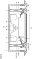
- a casing 21 contains fan 35, a fan motor 39, a bell mouth 23, a drain pan 43, and heat exchanger 41.
- Casing 21 has a panel 53 including an air intake grill 55 and an air outlet 59.
- Fan 35 has a rotational shaft 37, which is connected to fan motor 39. Fan 35 sucks indoor air into casing 21 through intake grill 55, and feeds the sucked air into a room through outlet 59 via heat exchanger 41. Bell mouth 23 directs air to fan 35. Bell mouth 23 has an opening 24 that opens toward fan 35. As shown in Fig. 3 , opening 24 has a circular shape, for example.
- drain pan 43 is disposed to surround bell mouth 23.
- Fig. 5 shows a state as seen from inside the casing. Drain pan 43 is fixed to casing 21.
- panel 53 includes intake grill 55 and outlet 59. Intake grill 55 has a rectangular shape, for example. Panel 53 is removably attached to casing 21. Panel 53 is disposed opposite to fan 35 with respect to bell mouth 23. A filter 57 is mounted on intake grill 55 at a distance from bell mouth 23.
- An electrical component box 51 is disposed between panel 53 and bell mouth 23. Electrical component box 51 is located in a region surrounded by drain pan 43. Electrical component box 51 contains a control board and the like (not shown) for controlling the operation of indoor unit 5.
- Fig. 6 shows a state as seen from outside the casing (inside the room).
- bell mouth 23 includes a first section 25, a second section 27 and a third section 29.
- First section 25 is formed such that opening 24 narrows toward fan 35.
- Opening 24 is formed to have an opening diameter that decreases toward fan 35.
- Second section 27 is disposed around first section 25 and connected to first section 25.
- Second section 27 includes a flat portion 27a as a first flat portion.
- Flat portion 27a is located in a direction crossing a central axis CA.
- Third section 29 is disposed around second section 27 and connected to second section 27 and to drain pan 43.
- Third section 29 includes a flat portion 29a as a second flat portion.
- Flat portion 29a is located in the direction crossing central axis CA.
- a distance in an axial direction of central axis CA between flat portion 27a of second section 27 and flat portion 29a of third section 29 is represented by L1.
- a distance in the axial direction of central axis CA between flat portion 27a of second section 27 and an open end of first section 25 is represented by L2.
- Distance L2 is set to be longer than distance L1 (L1 ⁇ L2).
- An inner circumferential portion 45 of drain pan 43 located on an inner circumferential side has a first extension 47 extending in the axial direction of central axis CA, and a second extension 49 extending in the direction crossing the axial direction of central axis CA.
- Third section 29 of bell mouth 23 is connected to second extension 49.
- Flat portion 27a of second section 27 of bell mouth 23 is located between second extension 49 of drain pan 43 and fan 35 in the axial direction of central axis CA.
- Flat portion 27a is located above second extension 49. Accordingly, a distance LA in the axial direction of central axis CA between flat portion 27a of second section 27 of bell mouth 23 and filter 57 is secured.
- Indoor unit 5 according to the first embodiment is configured as described above.
- bell mouth 23 including first section 25, second section 27 and third section 29 having a desired length relationship is disposed, which enables airflow resistance and the like to be suppressed. This is described in comparison with an indoor unit according to a comparative example.
- a bell mouth 123 is disposed for directing air sucked through intake grill 55 to fan 35.
- Bell mouth 123 includes a portion 123b extending from a lower end portion of second extension 49 at inner circumferential portion 45 of drain pan 43 toward central axis CA, and a portion 123a extending from that portion 123b toward fan 35 in a curved manner.
- portion 123b connecting portion 123a of bell mouth 123 to drain pan 43 extends from the lower end portion of second extension 49 of drain pan 43 toward central axis CA.
- portion 123b of bell mouth 123 is close to filter 57.
- a distance LB in the axial direction of central axis CA between portion 123b and filter 57 is shorter than distance LA (see Fig. 7 ) in indoor unit 5 according to the first embodiment.
- some of the air fed from fan 35 may flow from heat exchanger 41 toward bell mouth 123 (portion 123b) without passing through heat exchanger 41.
- the air that has flowed toward bell mouth 123 flows through a gap between bell mouth 123 and fan 35, and is fed into fan 35 along with air flowing through opening 24 in bell mouth 123.
- This flow of air that is fed into fan 35 again without passing through heat exchanger 41 in the air that was fed from fan 35 is called a circulating flow.
- the circulating flow will cause reduced efficiency of fan 35.
- bell mouth 23 includes first section 25, second section 27 having flat portion 27a, and third section 29 having flat portion 29a.
- Flat portion 27a of second section 27 is located above second extension 49 of drain pan 43.
- distance LA in the axial direction of central axis CA between flat portion 27a of second section 27 of bell mouth 23 and filter 57 is secured.
- distance LA velocity distribution of air flowing into opening 24 in bell mouth 23 is made more uniform than that in indoor unit 5 according to the comparative example, which enables the airflow resistance to be reduced.
- a portion of bell mouth 23 located between second section 27 and third section 29 in the axial direction of central axis CA serves as a resistance, to facilitate the flow of air passing through heat exchanger 41. Accordingly, the circulating flow of air fed into fan 35 again through a gap between bell mouth 23 and fan 35 can be reduced.
- distance L2 in the axial direction of central axis CA between second section 27 (flat portion 27a) and the end portion of first section 25 on the fan 35 side is set to be longer than distance L1 in the axial direction of central axis CA between second section 27 (flat portion 27a) and third section 29 (flat portion 29a) (L1 ⁇ L2).
- second section 27 and the third section of bell mouth 23 may be smoothly connected in a curved manner.
- a first inclined portion 27b inclined relative to central axis CA may be provided at a portion of second section 27 which is located at a circumferential position as a first circumferential position corresponding to a corner of intake grill 55 in a circumferential direction of bell mouth 23.
- a first inclination angle ⁇ 1 of first inclined portion 27b is desirably from 45° to 90°, for example. If first inclination angle ⁇ 1 is smaller than 45°, the effect of suppressing the circulating flow of air is reduced.
- First inclination angle ⁇ 1 is an angle formed with the direction crossing the axial direction of central axis CA.
- a second inclined portion 27c may be provided at a portion of second section 27 which is located at a circumferential position as a second circumferential position other than the circumferential positon at bell mouth 23 corresponding to the corner of intake grill 55.
- a second inclination angle ⁇ 2 of second inclined portion 27c is desirably set such that first inclination angle ⁇ 1 is smaller than second inclination angle ⁇ 2.
- first inclination angle ⁇ 1 to be smaller than second inclination angle ⁇ 2 can suppress the separation of air.
- the indoor unit according to a second embodiment is different in that the second extension at the inner circumferential portion of the drain pan has a thickness that varies between its portion where the electrical component box is disposed and its portion where the electrical component box is not disposed.
- electrical component box 51 is disposed between panel 53 and bell mouth 23. As shown in Fig. 12 , electrical component box 51 is disposed along one side of rectangular intake grill 55. In second extension 49 at inner circumferential portion 45 of drain pan 43, a thickness T1 of a second extension second section 49b where electrical component box 51 is disposed is smaller than a thickness T2 of a second extension first section 49a where electrical component box 51 is not disposed.
- a height position (position in the axial direction of central axis CA) of the upper end of inner circumferential portion 45 of drain pan 43 is set to a constant height position throughout the entire circumference of drain pan 43.
- the same members are denoted by the same reference characters and description thereof will not be repeated unless necessary.
- the indoor unit described above produces the following advantageous effects in addition to the advantageous effects described above.
- indoor air flows from intake grill 55 to opening 24 in bell mouth 23
- the passing of air through filter 57 is facilitated and airflow resistance of filter 57 is reduced.
- circumferential air velocity distribution in filter 57 becomes uniform in the circumferential direction.
- indoor unit 51 An indoor unit according to a third embodiment is described. As shown in Fig. 13 , in indoor unit 5, electrical component box 51 is disposed between panel 53 and bell mouth 23. Electrical component box 51 is disposed at a distance L3 from flat portion 27a of second section 27 of bell mouth 23.
- Electrical component box 51 is in contact with flat portion 29a of third section 29 of bell mouth 23. Electrical component box 51 is fixed such that flat portion 29a is sandwiched between electrical component box 51 and second extension 49 of drain pan 43.
- the same members are denoted by the same reference characters and description thereof will not be repeated unless necessary.
- a region of stagnant air flow may be generated in a region of electrical component box 51 on the bell mouth 23 side (downstream of the flow).
- indoor unit 5 produces the following advantageous effects in addition to the advantageous effects described in the first embodiment.
- Electrical component box 51 is disposed at distance L3 from flat portion 27a of second section 27 of bell mouth 23, and a gap is secured between electrical component box 51 and flat portion 27a of second section 27.
- FIG. 15 An indoor unit according to a fourth embodiment is described.
- ribs 31 are disposed on a surface of bell mouth 23 on the intake grill 55 side.
- Ribs 31 are formed radially toward central axis CA at a portion of a circumferential position as a third circumferential position corresponding to a corner (see a dotted frame DC) of rectangular intake grill 55 in the circumferential direction of bell mouth 23.
- the same members are denoted by the same reference characters and description thereof will not be repeated unless necessary.
- the quantity of air flowing from the corner of intake grill 55 toward opening 24 in bell mouth 23 is higher than the quantity of air flowing from portions other than the corner toward opening 24 in bell mouth 23.
- the velocity of air flowing from the corner of intake grill 55 toward opening 24 in bell mouth 23 tends to be higher than the velocity of air flowing from portions other than the corner toward opening 24 in bell mouth 23. It is thus assumed that the circumferential velocity distribution of air flowing from intake grill 55 toward opening 24 in bell mouth 23 will be uneven.
- Indoor unit 5 described above produces the following advantageous effects in addition to the advantageous effects described in the first embodiment.
- ribs 31 are formed at the portion of the circumferential position corresponding to the corner (see dotted frame DC) of rectangular intake grill 55 in the circumferential direction of bell mouth 23. Ribs 31 are formed radially toward central axis CA.
- ribs 31 act as airflow resistance, to reduce the velocity of air flowing from the corner of intake grill 55 toward opening 24 in bell mouth 23. Accordingly, the circumferential velocity distribution of air flowing from intake grill 55 toward opening 24 in bell mouth 23 can be made uniform.
- bell mouth 23 includes a first curvature portion 33a having a smaller curvature and a second curvature portion 33b having a larger curvature.
- first curvature portion 33a is disposed at a portion of a circumferential position as a fourth circumferential position corresponding to a corner of rectangular intake grill 55 in the circumferential direction of bell mouth 23.
- Second curvature portion 33b is disposed at a portion of a circumferential position as a fifth circumferential position corresponding to a portion other than the corner of rectangular intake grill 55 in the circumferential direction of bell mouth 23.
- a distance LC between the portion of bell mouth 23 where first curvature portion 33a is disposed and filter 57 is shorter than a distance LD between the portion of bell mouth 23 where second curvature portion 33b is disposed and filter 57.
- Fig. 17 shows cross sections of both first curvature portion 33a and second curvature portion 33b in order to simplify the drawing and to facilitate understanding of the difference in curvature between first curvature portion 33a and second curvature portion 33b.
- the same members are denoted by the same reference characters and description thereof will not be repeated unless necessary.
- Indoor unit 5 described above produces the following advantageous effects in addition to the advantageous effects described in the first embodiment.
- first curvature portion 33a having a small curvature is disposed at the portion of the circumferential positon at bell mouth 23 corresponding to the corner of rectangular intake grill 55.
- Second curvature portion 33b having a large curvature is disposed at the portion of the circumferential positon at bell mouth 23 corresponding to a portion other than the corner of intake grill 55.
- distance LC in the axial direction of central axis CA between the portion of bell mouth 23 where first curvature portion 33a is disposed and filter 57 is shorter than distance LD in the axial direction of central axis CA between the portion of bell mouth 23 where second curvature portion 33b is disposed and filter 57. Accordingly, as shown in Fig. 19 , when air flows from intake grill 55 toward opening 24 in bell mouth 23, the velocity of air flowing from the corner of intake grill 55 toward opening 24 in bell mouth 23 is reduced, which enables the circumferential velocity distribution of air flowing toward opening 24 in bell mouth 23 to be made uniform.
- the present invention is effectively utilized for an air conditioning apparatus including an indoor unit.
- 1 air conditioning apparatus 3 compressor; 5 indoor unit; 7 expansion valve; 9 outdoor heat exchanger; 13 outdoor fan; 15 four-way valve; 17 refrigerant pipe; 21 casing; 23 bell mouth; 24 opening; 25 first section; 27 second section; 27a flat portion; 27b first inclined portion; 27c second inclined portion; 29 third section; 29a flat portion; 31 rib; 33a first curvature portion; 33b second curvature portion; 35 fan; 37 rotational shaft; 39 fan motor; 41 heat exchanger; 43 drain pan; 45 inner circumferential portion; 47 first extension; 49 second extension; 49a second extension first section; 49b second extension second section; 51 electrical component box; 53 panel; 55 intake grill; 57 filter; 59 outlet; CA central axis; L1, L2, L3, LA, LB, LC, LD distance; T1, T2 thickness; DC dotted frame.
Landscapes
- Engineering & Computer Science (AREA)
- Chemical & Material Sciences (AREA)
- Combustion & Propulsion (AREA)
- Mechanical Engineering (AREA)
- General Engineering & Computer Science (AREA)
- Physics & Mathematics (AREA)
- Thermal Sciences (AREA)
- Air-Conditioning Room Units, And Self-Contained Units In General (AREA)
- Air Filters, Heat-Exchange Apparatuses, And Housings Of Air-Conditioning Units (AREA)
Applications Claiming Priority (1)
| Application Number | Priority Date | Filing Date | Title |
|---|---|---|---|
| PCT/JP2019/044400 WO2021095133A1 (ja) | 2019-11-12 | 2019-11-12 | 室内機およびそれを備えた空気調和装置 |
Publications (3)
| Publication Number | Publication Date |
|---|---|
| EP4060246A1 EP4060246A1 (en) | 2022-09-21 |
| EP4060246A4 EP4060246A4 (en) | 2022-11-30 |
| EP4060246B1 true EP4060246B1 (en) | 2023-06-14 |
Family
ID=75912092
Family Applications (1)
| Application Number | Title | Priority Date | Filing Date |
|---|---|---|---|
| EP19952643.5A Active EP4060246B1 (en) | 2019-11-12 | 2019-11-12 | Indoor unit and air conditioning device provided with same |
Country Status (3)
| Country | Link |
|---|---|
| EP (1) | EP4060246B1 (ja) |
| JP (1) | JP7386885B2 (ja) |
| WO (1) | WO2021095133A1 (ja) |
Family Cites Families (10)
| Publication number | Priority date | Publication date | Assignee | Title |
|---|---|---|---|---|
| JP3807088B2 (ja) * | 1998-03-31 | 2006-08-09 | 株式会社富士通ゼネラル | 天井埋込型空気調和機 |
| KR100697194B1 (ko) * | 2001-06-25 | 2007-03-21 | 주식회사 엘지이아이 | 천정형 공기조화기의 드레인 팬 고정구조 |
| JP2004156885A (ja) * | 2002-11-08 | 2004-06-03 | Mitsubishi Heavy Ind Ltd | 空調用室内ユニットおよび天井埋込型空気調和機 |
| JP5293684B2 (ja) * | 2010-06-03 | 2013-09-18 | 三菱電機株式会社 | 空気調和機の室内機 |
| JP2013108684A (ja) * | 2011-11-22 | 2013-06-06 | Hitachi Appliances Inc | 空気調和機の室内機 |
| JP6130137B2 (ja) * | 2012-12-26 | 2017-05-17 | 三菱重工業株式会社 | 空調ユニット |
| JP2014190656A (ja) * | 2013-03-28 | 2014-10-06 | Panasonic Corp | 四方向カセット型空気調和機、及び、ベルマウス |
| KR101900484B1 (ko) * | 2015-01-23 | 2018-09-20 | 삼성전자주식회사 | 공기 조화기 |
| EP3321597A4 (en) * | 2015-07-08 | 2019-02-27 | Hitachi-Johnson Controls Air Conditioning, Inc. | INDOOR UNIT FOR AIR CONDITIONING |
| JP6521249B2 (ja) * | 2015-09-03 | 2019-05-29 | 株式会社富士通ゼネラル | 天井埋込型空気調和機 |
-
2019
- 2019-11-12 JP JP2021555668A patent/JP7386885B2/ja active Active
- 2019-11-12 EP EP19952643.5A patent/EP4060246B1/en active Active
- 2019-11-12 WO PCT/JP2019/044400 patent/WO2021095133A1/ja unknown
Also Published As
| Publication number | Publication date |
|---|---|
| EP4060246A1 (en) | 2022-09-21 |
| EP4060246A4 (en) | 2022-11-30 |
| JPWO2021095133A1 (ja) | 2021-05-20 |
| WO2021095133A1 (ja) | 2021-05-20 |
| JP7386885B2 (ja) | 2023-11-27 |
Similar Documents
| Publication | Publication Date | Title |
|---|---|---|
| CN109891155B (zh) | 室内机及空调装置 | |
| US9568221B2 (en) | Indoor unit for air conditioning device | |
| CN111279085A (zh) | 离心送风机、送风装置、空调装置以及制冷循环装置 | |
| EP3040629B1 (en) | Outdoor device for an air conditioner | |
| US11319961B2 (en) | Centrifugal blower, air conditioner, and refrigeration cycle apparatus | |
| JP5295321B2 (ja) | 送風機、室外機及び冷凍サイクル装置 | |
| US10982688B2 (en) | HVAC fan assembly air inlet systems and methods | |
| US11480192B2 (en) | Cutoff for a blower housing | |
| JP6139669B2 (ja) | 空気調和機 | |
| US10962275B2 (en) | Condenser unit with fan | |
| TWI832906B (zh) | 離心式送風機、空調裝置以及冷凍循環裝置 | |
| EP4060246B1 (en) | Indoor unit and air conditioning device provided with same | |
| US10378781B2 (en) | Outdoor unit for refrigeration cycle apparatus, and refrigeration cycle apparatus | |
| JP2015068561A (ja) | 空気調和機の室内機 | |
| JP6363033B2 (ja) | 空気調和機の室内機およびこれを備えた空気調和機 | |
| KR102522048B1 (ko) | 천장형 공기조화기 | |
| CN113203119A (zh) | 天花板嵌入式空调 | |
| JP2018025357A (ja) | 室内機および空気調和機 | |
| CN116391097A (zh) | 室内机和制冷循环装置 | |
| CN109891101B (zh) | 螺旋桨风扇、室外机和制冷循环装置 | |
| JP6430032B2 (ja) | 遠心ファン、空気調和装置および冷凍サイクル装置 | |
| JP5558449B2 (ja) | 送風機、室外機及び冷凍サイクル装置 | |
| EP4431747A1 (en) | Cross-flow fan, blowing device, and refrigeration cycle device | |
| JP2018025354A (ja) | 室内機および空気調和機 | |
| WO2019198150A1 (ja) | 空気調和機 |
Legal Events
| Date | Code | Title | Description |
|---|---|---|---|
| STAA | Information on the status of an ep patent application or granted ep patent |
Free format text: STATUS: THE INTERNATIONAL PUBLICATION HAS BEEN MADE |
|
| PUAI | Public reference made under article 153(3) epc to a published international application that has entered the european phase |
Free format text: ORIGINAL CODE: 0009012 |
|
| STAA | Information on the status of an ep patent application or granted ep patent |
Free format text: STATUS: REQUEST FOR EXAMINATION WAS MADE |
|
| 17P | Request for examination filed |
Effective date: 20220505 |
|
| AK | Designated contracting states |
Kind code of ref document: A1 Designated state(s): AL AT BE BG CH CY CZ DE DK EE ES FI FR GB GR HR HU IE IS IT LI LT LU LV MC MK MT NL NO PL PT RO RS SE SI SK SM TR |
|
| A4 | Supplementary search report drawn up and despatched |
Effective date: 20221031 |
|
| RIC1 | Information provided on ipc code assigned before grant |
Ipc: F24F 13/22 20060101ALI20221026BHEP Ipc: F24F 13/20 20060101AFI20221026BHEP |
|
| DAV | Request for validation of the european patent (deleted) | ||
| DAX | Request for extension of the european patent (deleted) | ||
| GRAP | Despatch of communication of intention to grant a patent |
Free format text: ORIGINAL CODE: EPIDOSNIGR1 |
|
| STAA | Information on the status of an ep patent application or granted ep patent |
Free format text: STATUS: GRANT OF PATENT IS INTENDED |
|
| INTG | Intention to grant announced |
Effective date: 20230221 |
|
| GRAS | Grant fee paid |
Free format text: ORIGINAL CODE: EPIDOSNIGR3 |
|
| GRAA | (expected) grant |
Free format text: ORIGINAL CODE: 0009210 |
|
| STAA | Information on the status of an ep patent application or granted ep patent |
Free format text: STATUS: THE PATENT HAS BEEN GRANTED |
|
| AK | Designated contracting states |
Kind code of ref document: B1 Designated state(s): AL AT BE BG CH CY CZ DE DK EE ES FI FR GB GR HR HU IE IS IT LI LT LU LV MC MK MT NL NO PL PT RO RS SE SI SK SM TR |
|
| REG | Reference to a national code |
Ref country code: CH Ref legal event code: EP |
|
| P01 | Opt-out of the competence of the unified patent court (upc) registered |
Effective date: 20230512 |
|
| REG | Reference to a national code |
Ref country code: DE Ref legal event code: R096 Ref document number: 602019031218 Country of ref document: DE |
|
| REG | Reference to a national code |
Ref country code: AT Ref legal event code: REF Ref document number: 1579482 Country of ref document: AT Kind code of ref document: T Effective date: 20230715 |
|
| REG | Reference to a national code |
Ref country code: LT Ref legal event code: MG9D |
|
| REG | Reference to a national code |
Ref country code: NL Ref legal event code: MP Effective date: 20230614 |
|
| PG25 | Lapsed in a contracting state [announced via postgrant information from national office to epo] |
Ref country code: SE Free format text: LAPSE BECAUSE OF FAILURE TO SUBMIT A TRANSLATION OF THE DESCRIPTION OR TO PAY THE FEE WITHIN THE PRESCRIBED TIME-LIMIT Effective date: 20230614 Ref country code: NO Free format text: LAPSE BECAUSE OF FAILURE TO SUBMIT A TRANSLATION OF THE DESCRIPTION OR TO PAY THE FEE WITHIN THE PRESCRIBED TIME-LIMIT Effective date: 20230914 Ref country code: ES Free format text: LAPSE BECAUSE OF FAILURE TO SUBMIT A TRANSLATION OF THE DESCRIPTION OR TO PAY THE FEE WITHIN THE PRESCRIBED TIME-LIMIT Effective date: 20230614 |
|
| PGFP | Annual fee paid to national office [announced via postgrant information from national office to epo] |
Ref country code: GB Payment date: 20230928 Year of fee payment: 5 |
|
| REG | Reference to a national code |
Ref country code: AT Ref legal event code: MK05 Ref document number: 1579482 Country of ref document: AT Kind code of ref document: T Effective date: 20230614 |
|
| PG25 | Lapsed in a contracting state [announced via postgrant information from national office to epo] |
Ref country code: RS Free format text: LAPSE BECAUSE OF FAILURE TO SUBMIT A TRANSLATION OF THE DESCRIPTION OR TO PAY THE FEE WITHIN THE PRESCRIBED TIME-LIMIT Effective date: 20230614 Ref country code: NL Free format text: LAPSE BECAUSE OF FAILURE TO SUBMIT A TRANSLATION OF THE DESCRIPTION OR TO PAY THE FEE WITHIN THE PRESCRIBED TIME-LIMIT Effective date: 20230614 Ref country code: LV Free format text: LAPSE BECAUSE OF FAILURE TO SUBMIT A TRANSLATION OF THE DESCRIPTION OR TO PAY THE FEE WITHIN THE PRESCRIBED TIME-LIMIT Effective date: 20230614 Ref country code: LT Free format text: LAPSE BECAUSE OF FAILURE TO SUBMIT A TRANSLATION OF THE DESCRIPTION OR TO PAY THE FEE WITHIN THE PRESCRIBED TIME-LIMIT Effective date: 20230614 Ref country code: HR Free format text: LAPSE BECAUSE OF FAILURE TO SUBMIT A TRANSLATION OF THE DESCRIPTION OR TO PAY THE FEE WITHIN THE PRESCRIBED TIME-LIMIT Effective date: 20230614 Ref country code: GR Free format text: LAPSE BECAUSE OF FAILURE TO SUBMIT A TRANSLATION OF THE DESCRIPTION OR TO PAY THE FEE WITHIN THE PRESCRIBED TIME-LIMIT Effective date: 20230915 |
|
| PGFP | Annual fee paid to national office [announced via postgrant information from national office to epo] |
Ref country code: FR Payment date: 20230929 Year of fee payment: 5 |
|
| PG25 | Lapsed in a contracting state [announced via postgrant information from national office to epo] |
Ref country code: FI Free format text: LAPSE BECAUSE OF FAILURE TO SUBMIT A TRANSLATION OF THE DESCRIPTION OR TO PAY THE FEE WITHIN THE PRESCRIBED TIME-LIMIT Effective date: 20230614 |
|
| PG25 | Lapsed in a contracting state [announced via postgrant information from national office to epo] |
Ref country code: SK Free format text: LAPSE BECAUSE OF FAILURE TO SUBMIT A TRANSLATION OF THE DESCRIPTION OR TO PAY THE FEE WITHIN THE PRESCRIBED TIME-LIMIT Effective date: 20230614 |
|
| PG25 | Lapsed in a contracting state [announced via postgrant information from national office to epo] |
Ref country code: IS Free format text: LAPSE BECAUSE OF FAILURE TO SUBMIT A TRANSLATION OF THE DESCRIPTION OR TO PAY THE FEE WITHIN THE PRESCRIBED TIME-LIMIT Effective date: 20231014 |
|
| PG25 | Lapsed in a contracting state [announced via postgrant information from national office to epo] |
Ref country code: SM Free format text: LAPSE BECAUSE OF FAILURE TO SUBMIT A TRANSLATION OF THE DESCRIPTION OR TO PAY THE FEE WITHIN THE PRESCRIBED TIME-LIMIT Effective date: 20230614 Ref country code: SK Free format text: LAPSE BECAUSE OF FAILURE TO SUBMIT A TRANSLATION OF THE DESCRIPTION OR TO PAY THE FEE WITHIN THE PRESCRIBED TIME-LIMIT Effective date: 20230614 Ref country code: RO Free format text: LAPSE BECAUSE OF FAILURE TO SUBMIT A TRANSLATION OF THE DESCRIPTION OR TO PAY THE FEE WITHIN THE PRESCRIBED TIME-LIMIT Effective date: 20230614 Ref country code: PT Free format text: LAPSE BECAUSE OF FAILURE TO SUBMIT A TRANSLATION OF THE DESCRIPTION OR TO PAY THE FEE WITHIN THE PRESCRIBED TIME-LIMIT Effective date: 20231016 Ref country code: IS Free format text: LAPSE BECAUSE OF FAILURE TO SUBMIT A TRANSLATION OF THE DESCRIPTION OR TO PAY THE FEE WITHIN THE PRESCRIBED TIME-LIMIT Effective date: 20231014 Ref country code: EE Free format text: LAPSE BECAUSE OF FAILURE TO SUBMIT A TRANSLATION OF THE DESCRIPTION OR TO PAY THE FEE WITHIN THE PRESCRIBED TIME-LIMIT Effective date: 20230614 Ref country code: CZ Free format text: LAPSE BECAUSE OF FAILURE TO SUBMIT A TRANSLATION OF THE DESCRIPTION OR TO PAY THE FEE WITHIN THE PRESCRIBED TIME-LIMIT Effective date: 20230614 Ref country code: AT Free format text: LAPSE BECAUSE OF FAILURE TO SUBMIT A TRANSLATION OF THE DESCRIPTION OR TO PAY THE FEE WITHIN THE PRESCRIBED TIME-LIMIT Effective date: 20230614 |
|
| PGFP | Annual fee paid to national office [announced via postgrant information from national office to epo] |
Ref country code: DE Payment date: 20230929 Year of fee payment: 5 |
|
| PG25 | Lapsed in a contracting state [announced via postgrant information from national office to epo] |
Ref country code: PL Free format text: LAPSE BECAUSE OF FAILURE TO SUBMIT A TRANSLATION OF THE DESCRIPTION OR TO PAY THE FEE WITHIN THE PRESCRIBED TIME-LIMIT Effective date: 20230614 |
|
| REG | Reference to a national code |
Ref country code: DE Ref legal event code: R097 Ref document number: 602019031218 Country of ref document: DE |
|
| PLBE | No opposition filed within time limit |
Free format text: ORIGINAL CODE: 0009261 |
|
| STAA | Information on the status of an ep patent application or granted ep patent |
Free format text: STATUS: NO OPPOSITION FILED WITHIN TIME LIMIT |
|
| PG25 | Lapsed in a contracting state [announced via postgrant information from national office to epo] |
Ref country code: DK Free format text: LAPSE BECAUSE OF FAILURE TO SUBMIT A TRANSLATION OF THE DESCRIPTION OR TO PAY THE FEE WITHIN THE PRESCRIBED TIME-LIMIT Effective date: 20230614 |
|
| PG25 | Lapsed in a contracting state [announced via postgrant information from national office to epo] |
Ref country code: SI Free format text: LAPSE BECAUSE OF FAILURE TO SUBMIT A TRANSLATION OF THE DESCRIPTION OR TO PAY THE FEE WITHIN THE PRESCRIBED TIME-LIMIT Effective date: 20230614 |
|
| 26N | No opposition filed |
Effective date: 20240315 |
|
| PG25 | Lapsed in a contracting state [announced via postgrant information from national office to epo] |
Ref country code: SI Free format text: LAPSE BECAUSE OF FAILURE TO SUBMIT A TRANSLATION OF THE DESCRIPTION OR TO PAY THE FEE WITHIN THE PRESCRIBED TIME-LIMIT Effective date: 20230614 Ref country code: IT Free format text: LAPSE BECAUSE OF FAILURE TO SUBMIT A TRANSLATION OF THE DESCRIPTION OR TO PAY THE FEE WITHIN THE PRESCRIBED TIME-LIMIT Effective date: 20230614 |
|
| REG | Reference to a national code |
Ref country code: CH Ref legal event code: PL |
|
| PG25 | Lapsed in a contracting state [announced via postgrant information from national office to epo] |
Ref country code: MC Free format text: LAPSE BECAUSE OF FAILURE TO SUBMIT A TRANSLATION OF THE DESCRIPTION OR TO PAY THE FEE WITHIN THE PRESCRIBED TIME-LIMIT Effective date: 20230614 |
|
| PG25 | Lapsed in a contracting state [announced via postgrant information from national office to epo] |
Ref country code: LU Free format text: LAPSE BECAUSE OF NON-PAYMENT OF DUE FEES Effective date: 20231112 |
|
| PG25 | Lapsed in a contracting state [announced via postgrant information from national office to epo] |
Ref country code: CH Free format text: LAPSE BECAUSE OF NON-PAYMENT OF DUE FEES Effective date: 20231130 |
|
| PG25 | Lapsed in a contracting state [announced via postgrant information from national office to epo] |
Ref country code: MC Free format text: LAPSE BECAUSE OF FAILURE TO SUBMIT A TRANSLATION OF THE DESCRIPTION OR TO PAY THE FEE WITHIN THE PRESCRIBED TIME-LIMIT Effective date: 20230614 Ref country code: LU Free format text: LAPSE BECAUSE OF NON-PAYMENT OF DUE FEES Effective date: 20231112 Ref country code: CH Free format text: LAPSE BECAUSE OF NON-PAYMENT OF DUE FEES Effective date: 20231130 |
|
| REG | Reference to a national code |
Ref country code: BE Ref legal event code: MM Effective date: 20231130 |