EP4058978B1 - Image stitching in the presence of a full field of view reference image - Google Patents
Image stitching in the presence of a full field of view reference image Download PDFInfo
- Publication number
- EP4058978B1 EP4058978B1 EP21808995.1A EP21808995A EP4058978B1 EP 4058978 B1 EP4058978 B1 EP 4058978B1 EP 21808995 A EP21808995 A EP 21808995A EP 4058978 B1 EP4058978 B1 EP 4058978B1
- Authority
- EP
- European Patent Office
- Prior art keywords
- image
- fov
- tele
- images
- camera
- Prior art date
- Legal status (The legal status is an assumption and is not a legal conclusion. Google has not performed a legal analysis and makes no representation as to the accuracy of the status listed.)
- Active
Links
Images








Classifications
-
- G—PHYSICS
- G06—COMPUTING OR CALCULATING; COUNTING
- G06T—IMAGE DATA PROCESSING OR GENERATION, IN GENERAL
- G06T5/00—Image enhancement or restoration
- G06T5/50—Image enhancement or restoration using two or more images, e.g. averaging or subtraction
-
- G—PHYSICS
- G02—OPTICS
- G02B—OPTICAL ELEMENTS, SYSTEMS OR APPARATUS
- G02B13/00—Optical objectives specially designed for the purposes specified below
- G02B13/02—Telephoto objectives, i.e. systems of the type + - in which the distance from the front vertex to the image plane is less than the equivalent focal length
-
- G—PHYSICS
- G03—PHOTOGRAPHY; CINEMATOGRAPHY; ANALOGOUS TECHNIQUES USING WAVES OTHER THAN OPTICAL WAVES; ELECTROGRAPHY; HOLOGRAPHY
- G03B—APPARATUS OR ARRANGEMENTS FOR TAKING PHOTOGRAPHS OR FOR PROJECTING OR VIEWING THEM; APPARATUS OR ARRANGEMENTS EMPLOYING ANALOGOUS TECHNIQUES USING WAVES OTHER THAN OPTICAL WAVES; ACCESSORIES THEREFOR
- G03B17/00—Details of cameras or camera bodies; Accessories therefor
-
- G—PHYSICS
- G03—PHOTOGRAPHY; CINEMATOGRAPHY; ANALOGOUS TECHNIQUES USING WAVES OTHER THAN OPTICAL WAVES; ELECTROGRAPHY; HOLOGRAPHY
- G03B—APPARATUS OR ARRANGEMENTS FOR TAKING PHOTOGRAPHS OR FOR PROJECTING OR VIEWING THEM; APPARATUS OR ARRANGEMENTS EMPLOYING ANALOGOUS TECHNIQUES USING WAVES OTHER THAN OPTICAL WAVES; ACCESSORIES THEREFOR
- G03B37/00—Panoramic or wide-screen photography; Photographing extended surfaces, e.g. for surveying; Photographing internal surfaces, e.g. of pipe
- G03B37/04—Panoramic or wide-screen photography; Photographing extended surfaces, e.g. for surveying; Photographing internal surfaces, e.g. of pipe with cameras or projectors providing touching or overlapping fields of view
-
- G—PHYSICS
- G06—COMPUTING OR CALCULATING; COUNTING
- G06T—IMAGE DATA PROCESSING OR GENERATION, IN GENERAL
- G06T3/00—Geometric image transformations in the plane of the image
- G06T3/40—Scaling of whole images or parts thereof, e.g. expanding or contracting
- G06T3/4038—Image mosaicing, e.g. composing plane images from plane sub-images
-
- G—PHYSICS
- G06—COMPUTING OR CALCULATING; COUNTING
- G06T—IMAGE DATA PROCESSING OR GENERATION, IN GENERAL
- G06T3/00—Geometric image transformations in the plane of the image
- G06T3/40—Scaling of whole images or parts thereof, e.g. expanding or contracting
- G06T3/4053—Scaling of whole images or parts thereof, e.g. expanding or contracting based on super-resolution, i.e. the output image resolution being higher than the sensor resolution
-
- G—PHYSICS
- G06—COMPUTING OR CALCULATING; COUNTING
- G06T—IMAGE DATA PROCESSING OR GENERATION, IN GENERAL
- G06T7/00—Image analysis
- G06T7/30—Determination of transform parameters for the alignment of images, i.e. image registration
-
- H—ELECTRICITY
- H04—ELECTRIC COMMUNICATION TECHNIQUE
- H04N—PICTORIAL COMMUNICATION, e.g. TELEVISION
- H04N23/00—Cameras or camera modules comprising electronic image sensors; Control thereof
- H04N23/10—Cameras or camera modules comprising electronic image sensors; Control thereof for generating image signals from different wavelengths
-
- H—ELECTRICITY
- H04—ELECTRIC COMMUNICATION TECHNIQUE
- H04N—PICTORIAL COMMUNICATION, e.g. TELEVISION
- H04N23/00—Cameras or camera modules comprising electronic image sensors; Control thereof
- H04N23/60—Control of cameras or camera modules
- H04N23/69—Control of means for changing angle of the field of view, e.g. optical zoom objectives or electronic zooming
-
- H—ELECTRICITY
- H04—ELECTRIC COMMUNICATION TECHNIQUE
- H04N—PICTORIAL COMMUNICATION, e.g. TELEVISION
- H04N23/00—Cameras or camera modules comprising electronic image sensors; Control thereof
- H04N23/60—Control of cameras or camera modules
- H04N23/698—Control of cameras or camera modules for achieving an enlarged field of view, e.g. panoramic image capture
-
- H—ELECTRICITY
- H04—ELECTRIC COMMUNICATION TECHNIQUE
- H04N—PICTORIAL COMMUNICATION, e.g. TELEVISION
- H04N23/00—Cameras or camera modules comprising electronic image sensors; Control thereof
- H04N23/80—Camera processing pipelines; Components thereof
- H04N23/81—Camera processing pipelines; Components thereof for suppressing or minimising disturbance in the image signal generation
-
- H—ELECTRICITY
- H04—ELECTRIC COMMUNICATION TECHNIQUE
- H04N—PICTORIAL COMMUNICATION, e.g. TELEVISION
- H04N23/00—Cameras or camera modules comprising electronic image sensors; Control thereof
- H04N23/90—Arrangement of cameras or camera modules, e.g. multiple cameras in TV studios or sports stadiums
-
- H—ELECTRICITY
- H04—ELECTRIC COMMUNICATION TECHNIQUE
- H04N—PICTORIAL COMMUNICATION, e.g. TELEVISION
- H04N23/00—Cameras or camera modules comprising electronic image sensors; Control thereof
- H04N23/95—Computational photography systems, e.g. light-field imaging systems
- H04N23/951—Computational photography systems, e.g. light-field imaging systems by using two or more images to influence resolution, frame rate or aspect ratio
-
- H—ELECTRICITY
- H04—ELECTRIC COMMUNICATION TECHNIQUE
- H04N—PICTORIAL COMMUNICATION, e.g. TELEVISION
- H04N5/00—Details of television systems
- H04N5/222—Studio circuitry; Studio devices; Studio equipment
- H04N5/262—Studio circuits, e.g. for mixing, switching-over, change of character of image, other special effects ; Cameras specially adapted for the electronic generation of special effects
- H04N5/2625—Studio circuits, e.g. for mixing, switching-over, change of character of image, other special effects ; Cameras specially adapted for the electronic generation of special effects for obtaining an image which is composed of images from a temporal image sequence, e.g. for a stroboscopic effect
-
- H—ELECTRICITY
- H04—ELECTRIC COMMUNICATION TECHNIQUE
- H04N—PICTORIAL COMMUNICATION, e.g. TELEVISION
- H04N5/00—Details of television systems
- H04N5/222—Studio circuitry; Studio devices; Studio equipment
- H04N5/262—Studio circuits, e.g. for mixing, switching-over, change of character of image, other special effects ; Cameras specially adapted for the electronic generation of special effects
- H04N5/2628—Alteration of picture size, shape, position or orientation, e.g. zooming, rotation, rolling, perspective, translation
-
- H—ELECTRICITY
- H04—ELECTRIC COMMUNICATION TECHNIQUE
- H04N—PICTORIAL COMMUNICATION, e.g. TELEVISION
- H04N5/00—Details of television systems
- H04N5/222—Studio circuitry; Studio devices; Studio equipment
- H04N5/262—Studio circuits, e.g. for mixing, switching-over, change of character of image, other special effects ; Cameras specially adapted for the electronic generation of special effects
- H04N5/265—Mixing
-
- G—PHYSICS
- G06—COMPUTING OR CALCULATING; COUNTING
- G06T—IMAGE DATA PROCESSING OR GENERATION, IN GENERAL
- G06T2207/00—Indexing scheme for image analysis or image enhancement
- G06T2207/20—Special algorithmic details
- G06T2207/20212—Image combination
- G06T2207/20221—Image fusion; Image merging
Definitions
- Multi-aperture cameras are the standard for high-end mobile handheld devices ("mobile devices”, e.g. smartphone, tablet, etc.).
- a multi-camera usually comprises a wide field of view (FOVw) or "wide angle" camera ("Wide” camera or “W camera”), and one or more additional cameras, either with the same FOV, with a narrow FOV (Telephoto or "Tele” camera or “T” camera with Tele FOV T ) or an ultra-wide camera with a FOVuw > FOVw (“UW camera”).
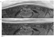
- FIG. 1 illustrates one difference between (a) a known panorama image (or simply “panorama”) and (b) a super image disclosed herein.
- the panorama image has an inherent perspective distortion due to the lack of "ground truth” when correcting points-of-view (POVs) of the different images forming it, while a super image disclosed herein is not distorted.
- FIG. 2 illustrates another difference between (a) a R image and (c) a SI obtained as disclosed herein.
- FIG. 2(b) shows the single Tele images used to compose the SI. Since a Tele camera with a large effective focal length (EFL) is used to capture the images, one achieves in the SI (c) a "natural" Bokeh effect. Natural Bokeh is defined as the amount of blurring present in the image data of FOV segments that are not in-focus.
- ETL effective focal length
- the present invention provides a method as defined in the appended claims.
- FIG. 4B shows a flow chart of SWM embodiments for obtaining a new image with RES N > RES R and/or SNR N > SNR R wherein the new image is a SW disclosed herein.
- An algorithm performing the methods may run on AP 1740 operatively coupled to a first (R) camera and a second (Tele) camera, as shown in FIG. 17 .
- a R image is retrieved.
- features present in the R image are extracted as known in the art and clustered in 426. The features may be clustered by their distance from the mobile device 1700, or by their location within the R image's FOV or otherwise, e.g. by their similarity in a semantic sense, e.g.
- a new image having RES N > RES R and/or SNR N > SNR R is output in step 444.
- FOV N is larger than the union of all FOV TS that are fed into the super-resolution algorithm in step 442, i.e. FOV N >union-FOV T .
- Union-FOV T represents the FOV within FOV R which is included in at least one FOV T of one of the T images captured in step 428.
- FIG. 5 illustrates exemplary FOVs of a dual-camera image, for a dual-camera that comprises for example a W camera (acting as a R camera) and a scanning T camera.
- Tele FOV 0 shows one exemplary T scanning position superposed on the Wide FOV
- FOV 1 shows another exemplary T scanning position superposed on the Wide FOV.
- a scanning order criterion may be to capture scene segments having similar depths consecutively, because this may minimize the amount of time required for re-focusing the T camera between single T image captures and may also facilitate the alignment of the T images.
- a plurality of sub-SIs that form a single SI may be captured in the FOV of a R image simultaneously, i.e. in a single capture process as described in FIG. 4 .
- a sub-SI is defined by being a part of a single SI, wherein the single SI covers a larger FOV of a scene than the sub-SI.
- a sub-SI has no FOV overlap with respect to all other sub-SIs.
- a scanning order criterion for capturing the single SI may be fast SI capture. Fast SI capture may be achieved by minimizing delay time between the capture of single T images caused by OPFE actuation.
- a scanning order criterion for capturing the single SI may be fast capture of the specific sub-SI that comprises the fastest moving object in the scene of the single SI.
- FIGS. 12C-12D show the same scene shown in FIGS. 10A , 11A and 12A .
- FIG. 12C shows the T scanning order in a flow chart.
- FIG. 12D shows the resulting SW.
- FIG. 12C shows a first example of a T scanning order that prioritizes capturing moving objects (such as the runner) over stationary objects (such as the city landscape).
- a first Tele FOV1 may be capture such as shown here, but a second Tele FOV2 that may still include the legs of the runner may be captured at a significantly later time, e.g. when the runner moved already to another position.
- a "significantly later time” may be for example a time that is 100ms later or 250ms later or 500ms later or even later than that, e.g. 1s later.
- one may follow an object with an object tracker for capturing a T image.
Landscapes
- Engineering & Computer Science (AREA)
- Multimedia (AREA)
- Signal Processing (AREA)
- Physics & Mathematics (AREA)
- General Physics & Mathematics (AREA)
- Theoretical Computer Science (AREA)
- Computing Systems (AREA)
- Computer Vision & Pattern Recognition (AREA)
- Optics & Photonics (AREA)
- Studio Devices (AREA)
- Image Processing (AREA)
Description
- The subject matter disclosed herein relates in general to image stitching and in particular to methods for stitching images taken with a small FOV camera in the presence of a large FOV image.
- Multi-aperture cameras (or multi-cameras) are the standard for high-end mobile handheld devices ("mobile devices", e.g. smartphone, tablet, etc.). A multi-camera usually comprises a wide field of view (FOVw) or "wide angle" camera ("Wide" camera or "W camera"), and one or more additional cameras, either with the same FOV, with a narrow FOV (Telephoto or "Tele" camera or "T" camera with Tele FOVT) or an ultra-wide camera with a FOVuw > FOVw ("UW camera").
- The Tele-Wide or Tele-Ultra-Wide multi-camera (which in the following may be referred to as a "Tele-Reference" multi-camera) combines benefits of both cameras to overcome shortcomings. It captures a large reference camera FOVR of the scene with the reference camera ("R camera") that provides reference (R) images with a R camera resolution ("RESR") and R signal-to-noise ratio (SNRR) and uses the higher Tele camera resolution ("REST") and SNR (SNRT) to zoom into the scene with FOVT. However, as the Tele camera resolution increases, FOVT narrows, so that only a fraction of a scene can be captured.
- A recent development is a scanning Tele camera that can scan a scene with its regular (native) FOVT, so that it effectively covers a scanning FOVT larger than native FOVT. A scanning Tele camera is described for example in co-owned
US patent 10,578,948 -
US 2019/121216 A1 (SHABTAY GAL [IL] ET AL, 25 April 2019 ) discloses a digital camera comprising an upright Wide camera configured to provide a Wide image with a Wide image resolution and a folded Tele camera configured to provide a Tele image with a Tele image resolution higher than the Wide image resolution, the Wide and Tele cameras having respective Wide and Tele fields of view FOVW and FOVT and respective Wide and Tele image sensors, the digital camera further comprising a rotating OPFE (optical path folding element) operative to provide a folded optical path between an object or scene and the Tele image sensor, wherein rotation of the OPFE moves FOVT relative to FOVW. When included in a host device having a user interface that displays FOVT within FOVW, the user interface may be used to position FOVT relative to FOVW, scan FOVT across FOVW and acquire, store and display separate Wide and Tele images, composite Wide plus Tele images and stitched Tele images. The positioning of FOVT within FOVW, can be done automatically (autonomously) by continuously tracking an object of interest. However inUS 2019/121216 A1 the Tele field of view FOVT cannot be scanning in both vertical and horizontal directions. - There is need and it would be beneficial to have methods for using reference image (R image) data and Tele (T) image data to create a new image with a "new" field of view FOVN that fulfills FOVT < FOVN ≤ FOVR, wherein the image resolution of the new image RESN > RESR and/or wherein the SNR of the new image SNRN > SNRR.
- In various embodiments, there are provided systems and methods for using reference image data and Tele image data to create a "new" image with a "new" field-of-view FOVN that fulfills FOVT < FOVN ≤ FOVR. The new image is a seamless, high resolution, large FOV image. The new image has a resolution RESN greater than RESR and/or a signal-to-noise ratio SNRN greater than SNRR. The new image can be a "super image" ("SI"), obtained by capturing and stitching two or more T images, or it can be a "super-wide image" ("SW"), obtained by capturing and using one or more T images to improve a R image or segments thereof with a super-resolution algorithm.
-
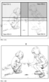
FIG. 1 illustrates one difference between (a) a known panorama image (or simply "panorama") and (b) a super image disclosed herein. The panorama image has an inherent perspective distortion due to the lack of "ground truth" when correcting points-of-view (POVs) of the different images forming it, while a super image disclosed herein is not distorted. - A SI comprises at least two high resolution Tele images and a R image (with RESR<REST) with a large FOV (e.g. FOVw or FOV uw) of the same scene, see
FIG. 1(b) . That is, a SI uses information regarding the same scene from a larger FOV reference image. In contrast, for creating a panorama as known in the art, in general no reference image is available. In a SI, each captured Tele image is processed and matched to its corresponding location in the larger FOV reference image, thus removing the normal panoramic image perspective distortion. In addition, each Tele image may be checked for capture issues such as focus miss, large amounts of noise, temporary occlusions and more, and, if necessary, is retaken at a later time. -
FIG. 2 illustrates another difference between (a) a R image and (c) a SI obtained as disclosed herein.FIG. 2(b) shows the single Tele images used to compose the SI. Since a Tele camera with a large effective focal length (EFL) is used to capture the images, one achieves in the SI (c) a "natural" Bokeh effect. Natural Bokeh is defined as the amount of blurring present in the image data of FOV segments that are not in-focus. -
FIG. 3 illustrates yet another difference between a known panorama and a SI obtained as disclosed herein. One can see a scenario where two Tele images, Tele1 and Tele 2, have no information in an overlapping FOV region, but the images are not entirely without information. In this situation, a known panorama will fail to align the images while the SI will be able to align them using a R image. - Other differences between a known panorama and a SI include the ability in the SI acquisition to scan automatically, thereby enabling to determine the scanning position and order of the Tele camera in an educated fashion; the ability to detect and correct bad images; and increased robustness due to higher overlap with the ground truth instead of overlap between different Tele images, which requires a smaller amount of images to cover a desired FOV, since the overlap size demand between the Tele images is reduced.
- The present invention provides a method as defined in the appended claims.
- A method disclosed herein is not limited to a specific multi-camera module, and could be used for any combination of cameras as long as the combination consists of at least one camera with some scanning capabilities, not limited to 2D scanning.
- Non-limiting examples of embodiments disclosed herein are described below with reference to figures attached hereto that are listed following this paragraph. Identical structures, elements or parts that appear in more than one figure are generally labeled with a same numeral in all the figures in which they appear. If identical elements are shown but numbered in only one figure, it is assumed that they have the same number in all figures in which they appear. The drawings and descriptions are meant to illuminate and clarify embodiments disclosed herein and should not be considered limiting in any way. In the drawings:
-
FIG. 1 illustrates a key difference between (a) a regular panorama image and (b) a super image; -
FIG. 2 illustrates another key difference between a regular panorama image and a super image obtained as disclosed herein; -
FIG. 3 illustrates yet another key difference between a regular panorama image and a super image obtained as disclosed herein; -
FIG. 4A shows a flow chart of method embodiments for obtaining a new image disclosed herein; -
FIG. 4B shows a flow chart of SWM embodiments for obtaining a new image, wherein the new image is a SW disclosed herein; -
FIG. 5 illustrates the FOVs of dual-camera output images; -
FIG. 6 illustrates an embodiment of a R image retrieval process; -
FIG. 7 illustrates another embodiment of a R image retrieval process; -
FIG. 8A illustrates an embodiment of Tele scanning order determination for creating a SI or SW; -
FIG. 8B illustrates another embodiment of determining a Tele scanning order for creating a SI or SW; -
FIG. 9 illustrates determination of Tele FOV positions according to certain criteria; -
FIG. 10A illustrates Tele camera scanning order in an embodiment of Tele scanning order determination based on the detection of a moving object in a scene; -
FIG. 10B illustrates a super image resulting for the scanning inFIG. 10A ; -
FIG. 11A illustrates Tele camera scanning order in another embodiment of Tele scanning order determination based on the detection of a moving object in a scene; -
FIG. 11B illustrates a super image resulting for the scanning inFIG. 11A ; -
FIG. 12A illustrates Tele camera scanning order in yet another embodiment of Tele scanning order determination based on the detection of a moving object in a scene; -
FIG. 12B illustrates a super image resulting for the scanning inFIG. 12A ; -
FIG. 12C shows a first example of a T scanning order that prioritizes capturing moving objects over stationary objects; -
FIG. 12D shows a SW resulting from the scanning order inFIG. 12C ; -
FIG. 13 is a flow chart showing details of a typical setup of the image alignment step; -
FIG. 14 illustrates a few cases in which the fault detection step will raise an error; -
FIG. 15A is a flow chart showing steps of a method for SI composition; -
FIG. 15B is a flow chart showing steps of a SWM; -
FIG. 16A shows a super image without the use of any color correction step; -
FIG. 16B shows a super image having the color correction step; -
FIG. 17 shows schematically an embodiment of a mobile device that includes multi-aperture cameras with at least one scanning Tele camera. - Returning now to the figures,
FIG. 4A shows a flow chart of method embodiments for obtaining a new image with RESN > RESR and/or SNRN > SNRR disclosed herein. A first method may be referred to as Super-Image method (or "SIM") for creating a super-image as described herein (for SI composition seeFIG. 15A ). A second method may be referred to as Super-Wide image method (or "SWM") for creating a super-wide image as described herein (for SW composition seeFIG. 15B ). An algorithm performing the methods may run on a processor such as Application processor (AP) 1740 operatively coupled to a first (R) camera and a second (Tele) camera, as shown inFIG. 17 . In some embodiments for obtaining a SI, an initial Tele image at an initial scanning position is captured instep 402. A R image is retrieved in step 404. In some embodiments, the R image is a W image or an UW image taken with respective cameras. In some embodiments, the R image is taken at a significantly different time than the Tele images captured instep 402 and/or 408, e.g. few seconds, hours or even years before the capturing of the Tele images. In other embodiments, the R image is retrieved from an external database using the initial Tele image as a query, see below. A next (also referred to as "subsequent", "sequential" or "consecutive") scanning position of the Tele camera, determining a respective FOVT, is selected or updated after the initial and each subsequent Tele image capture instep 406. - In step 408, a subsequent Tele image is acquired (captured) using the scanning position selected or updated in
step 406. For a SIM, the subsequently acquired Tele image is aligned with previously found Tele images that have some shared FOV and with the R image in step 410 to obtain an aligned Tele image. For a SWM, the subsequently acquired Tele image is aligned with the R image in step 410 to obtain an aligned Tele image. The aligned Tele image is analyzed for faults instep 412 and, based on the detected faults, a subsequent scanning position is updated by returning to step 406. Steps 406-412 are repeated until the desired coverage of the R image has been achieved. Afterwards, the SI or SW are composed as described inFIG. 15A for SIM and inFIG. 15B for SWM in step 414 to form one cohesive new image with FOVN>FOVT and RESN>REST and/or SNRN>SNRT, which can be a SI or a SW. - In some embodiments, image composition step 414 may be performed after all the Tele images are acquired and aligned as described above. In other embodiments, image composition step 414 may be performed after each iteration of Tele image acquisition and image alignment steps 406-412, to perform "on the fly" blending with intermediate viable results. In such embodiments, a SI exists after each iteration of steps 406-412.
-
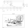
FIG. 4B shows a flow chart of SWM embodiments for obtaining a new image with RESN > RESR and/or SNRN > SNRR wherein the new image is a SW disclosed herein. An algorithm performing the methods may run onAP 1740 operatively coupled to a first (R) camera and a second (Tele) camera, as shown inFIG. 17 . Instep 422, a R image is retrieved. Instep 424, features present in the R image are extracted as known in the art and clustered in 426. The features may be clustered by their distance from themobile device 1700, or by their location within the R image's FOV or otherwise, e.g. by their similarity in a semantic sense, e.g. by semi-image segmentation such as "SLIC Superpixels" described by Radhakrishna Achanta, Appu Shaji, Kevin Smith, Aure-lien Lucchi, Pascal Fua, and Sabine Susstrunk, SLIC Superpixels, EPFL TechnicalReport 149300, June 2010. Based on the result of the clustering, in step 428 a T scanning order is determined. Optionally and in case thatT camera 1710 is a multi-zoom T camera having different zoom states, additionally a suitable zoom factor (ZF) may be determined. Examples for a T scanning order are given inFIG. 12C-D . Instep 430, T images are captured according to the T scanning order determined instep 428. - Steps 432 - 440 describe the process of aligning the T images captured in
step 430 with the R image retrieved instep 422. Further details on the image alignment are described inFIG. 13 . As known in the art, T images captured with a scanning T camera based on 1 OPFE undergo a "Roll effect", so that they are rectified instep 432. Features in the T images are extracted instep 434. For each T image, the features extracted instep 434 are matched with the features in R image that were extracted instep 424. Steps 438 - 440 describe the fine-tuning of the alignment process. Instep 438, in case the rectification performed instep 432 was found to be insufficient instep 436, the T image is additionally adjusted in terms of warping for reducing Roll effect. Instep 440, a localization of the T image data with respect to the R image data is performed. For example, a cross correlation calculation as known in the art may be performed for localizing the T image data within the R image. As an example and typically, before the localization, image points of a same object point may e.g. deviate by more than 25 pixels or by more than 50 pixels or by more than 100 pixels between the R and T images. We assume a pixel size of about 1µm. After the localization, image points of a same object point may e.g. deviate by less than 20 pixels or by less than 10 pixels or even by less than 2 pixels between the R and T images. For SWM, it may not be required to align the T images with respect to each other, but each T image may be aligned with the R image only. - In
step 442, the R image and the aligned T images are fed into a super-resolution algorithm. Relevant super-resolution algorithms are described for example in Daniel Glasner et al., "Super-Resolution from a Single Image", ICCV, 2009, Tamar Rott Shaham et al., "SinGAN: Learning a Generative Model from a Single Natural Image", ICCV, 2019, arXiv: 1905.01164, or Assaf Shocher et al.,"Zero-Shot Super-Resolution using Deep Internal Learning", 2017, arXiv: 1712.06087. - A new image having RESN > RESR and/or SNRN > SNRR is output in
step 444. In general, FOVN is larger than the union of all FOVTS that are fed into the super-resolution algorithm instep 442, i.e. FOVN>union-FOVT. Union-FOVT represents the FOV within FOVR which is included in at least one FOVT of one of the T images captured instep 428. - The FOVT scanning may be performed by actuating (e.g. for rotation) one or more optical path folding elements (OPFEs) of the scanning Tele camera. Fast actuation may be desired. Actuation may be performed in 2-20 ms for scanning e.g. 2°-5° and in 10-70 ms for scanning 15-25°. A scanning Tele camera may have a maximal diagonal scanning range of 60°. "Maximal diagonal scanning range" is defined by the center of the FOV in the maximum state bottom-left of a center FOV and the center of the FOV in the maximum state top-right of a center FOV. For example and referring to FOV diagonal, a scanning T camera having FOVT=20° and 60° scanning range covers an overall FOV of 80°. A diagonal scanning range of 40° may cover around 60-100% of a FOVw. The scanning Tele camera may have an of EFL=7mm-40mm. Typical zoom factors (ZF) may be 2x-10x zoom with respect to a W camera hosted in the same mobile device, meaning that an image of a same object captured at a same distance is projected at a size 2x-10x larger on the image sensor of the T camera than on the W camera. Assuming that a same sensor is used in R camera and T camera, the image resolution scales linearly with the ZF. For same sensors, typically, REST>2x RESW. In some examples, REST>5x RESW.
-
FIG. 5 illustrates exemplary FOVs of a dual-camera image, for a dual-camera that comprises for example a W camera (acting as a R camera) and a scanning T camera. Tele FOV 0 shows one exemplary T scanning position superposed on the Wide FOV andFOV 1 shows another exemplary T scanning position superposed on the Wide FOV. Such a setup enables the use of the W image as the R image in step 404. -
FIG. 6 illustrates an embodiment of a R image retrieval process. Three T images Tele1, Tele2 and Tele3 are acquired insteps 402 and/or 408. These images are then used to search an external database (e.g. using Google) for a similar image, which is then retrieved and used as the R image. -
FIG. 7 illustrates another embodiment of a R image retrieval process. Here, the retrieval is performed using GPS location from a mobile device. The figure shows the current mobile device's GPS location and two T images (Tele1 and Tele2) captured instep 402 and/or 408, and "GPS" R images retrieved from an external database using the GPS location as a query. -
FIG. 8A illustrates an embodiment of Tele (T) scanning order determination for creating a SI or SW (step 406 or step 428 respectively). The scanning order is indicated by numbering the images from 1-9, i.e.T image 1 havingTele FOV 1 is the first T image captured,T image 2 having Tele FOV 2is the second T image captured, etc. Here, the scanning positions are determined based on the maximal coverage of the T camera's scan range. The figure shows the maximal possible scanning range coverage of the T camera superimposed on a Wide FOV, and T images with Tele FOVs from FOV1 to FOV9 selected so as to achieve the maximal coverage. For creating a SW, the overlap between the single Tele images 1-9 is optional. -
FIG. 8B illustrates another embodiment of determining a T scanning order for creating a SI or SW (step 406 or step 428 respectively). The scanning order is indicated by numbering as seeFIG. 8A . Here, the scanning positions are determined based on the maximal coverage of the scan range and additionally on capturing this maximal coverage in the shortest overall capture time. The capture time includes consecutively moving FOVT to the target scanning position and capturing one or more T images at this position. In this embodiment, by minimizing the FOVT movement betweenT image 3 havingTele FOV 3 andT image 4, and betweenT image 6 andT image 7, a shorter overall capture time compared to the scanning order shown inFIG. 8A is achieved. - It is noted that determining a scanning order includes determining the respective FOVT position, meaning that FOVT positions and their scanning order are determined.
-
FIG. 9 illustrates determining Tele FOV positions for creating a SI and or a SW according to the criteria of maximal coverage of a user's region of interest (ROI) choice. The figure shows the user's requested ROI as a dashed rectangle on the Wide (as reference) image FOV and the T images determined so as to achieve the maximal coverage of this ROI choice. - In other embodiments for SIM and SWM, the scanning positions may be determined based on the maximal coverage of an object of interest or ROI as obtained from an algorithm, e.g. from a Saliency map, for example as described in "Salient Object Detection: A Discriminative Regional Feature Integration Approach" by Jiang et al. or as in "You Only Look Once: Unified, Real-Time Object Detection" by Redmon et al. The FOV of a SI or a SW may be selected based on the Saliency map.
- In yet other embodiments for SIM, the scanning positions may be determined such that specific features within an ROI are located in a center region of a FOVT and not in an overlap region. A specific feature may be for example the face of a person. Locating specific features in a center region may avoid stitching artifacts in the SI's FOV segments where the ROI is located, e.g. by applying "stitching seams" in the FOV covered by the specific feature.
- In yet other embodiments for SIM and SWM, scanning positions may be determined so that a minimal number of T image captures is required for a given selected ROI covering a particular FOV which is larger than FOVT, e.g. for reducing power consumption and capture time.
- In yet other embodiments for SIM and SWM, a criterion for determining an order of scanning position may be based on artistic or visual effects such as e.g. a desired amount of natural Bokeh. The amount of natural Bokeh depends on differences in the object-lens distance of foreground objects (in-focus) and background objects (out-of-focus). A scanning position criterion may e.g. be an image background with uniform natural Bokeh.
- In yet other embodiments for SIM and SWM, a criterion for determining an order of scanning position may be based on desired data for computational photography. Such data may be for example stereo image data including T image data and image data from the R image. From stereo image data of a single FOVT and the overlapping image FOV segment of the FOVR, a stereo depth map covering FOVT may be calculated as known in the art, e.g. by triangulation. The stereo depth map may enable application of artificial Bokeh algorithms to the R image or to the SI. In some embodiments, the SI output in step 414 may not be an image including visual data, but an output that includes stereo depth data.
- In other embodiments, a scanning order criterion may include desired artistic SI effects. Such effects may be created by synchronizing T image capture and FOV scanning, wherein capture happens during FOV movement, so that a motion blur effect in the T image is achieved. For this, a scanning order criterion may be a desired amount of motion blur of a specific scene segment.
- In yet other embodiments for SIM and SWM, a criterion for scanning position determination may be based on a depth estimation of the scene included in the R image. For example, one may select scanning positions so that single T images include scene segments having a specific depth range (i.e. a specific camera-object distance range) or include scene segments that do not exceed a specific depth threshold. In another example, one may select scanning positions so that single T images include ROIs covering a particular FOV size. As an example, a scanning order criterion may be to capture scene segments having similar depths or including ROIs of particular FOV sizes consecutively. This may be beneficial for a scanning camera that may have not one fixed FOV (i.e. zoom state) but different FOVs (zoom states). For fast SI or SW capture, one may prefer to capture FOV segments with identical zoom states consecutively (sequentially), as it may e.g. be desired to minimize number of (time-consuming) zoom state switches. As another example, a scanning order criterion may be to capture scene segments having similar depths consecutively, because this may minimize the amount of time required for re-focusing the T camera between single T image captures and may also facilitate the alignment of the T images.
- In yet another embodiment for SIM and SWM, a scanning order criterion may be that T images comprising specific scene characteristics within their respective FOVTS may be captured consecutively. In some embodiments, T images with similar scene characteristics within their respective FOVTS may be captured consecutively. Scene characteristics may be visual data such as texture. Scene characteristics may be physical data such as brightness, depth or spectroscopic composition of a scene. A spectroscopic composition may be defined by the intensity values of all wavelengths present in the scene.
-
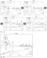
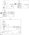
FIGS. 10A, 10B ,11A, 11B ,12A and 12B illustrate three examples for criteria for determining a T scanning order for creating a SI based on the information related to a moving object (a runner, the arrow inFIG. 11A indicating the direction of her movement) in the scene. Views A in each figure show the T scanning order in a flow chart (arrows - One can determine the order of capturing the T images such that the moving object will not appear in the scene at all, as illustrated in
FIG. 10A . Alternatively, one can determine the T scanning order such that the moving object will appear in the scene only once, as illustrated inFIG. 11A . Further alternatively, one can determine the T scanning order to create duplication of the moving object in the scene as illustrated inFIG. 12A . - The T scanning order (i.e. the scanning order criteria) may alternatively be based on camera or scene properties. In some embodiments, a scanning order criterion may be based on fast SI capture. In some embodiments, the SI output in step 414 or the SW output in
step 444 may not be an image including visual data, but it may be an output including spectroscopic data, stereo depth data or other image data that is generated by computational photography or physical analysis. - In some embodiments, a plurality of sub-SIs that form a single SI may be captured in the FOV of a R image simultaneously, i.e. in a single capture process as described in
FIG. 4 . A sub-SI is defined by being a part of a single SI, wherein the single SI covers a larger FOV of a scene than the sub-SI. A sub-SI has no FOV overlap with respect to all other sub-SIs. A scanning order criterion for capturing the single SI may be fast SI capture. Fast SI capture may be achieved by minimizing delay time between the capture of single T images caused by OPFE actuation. In other embodiments, a scanning order criterion for capturing the single SI may be fast capture of the specific sub-SI that comprises the fastest moving object in the scene of the single SI. -
FIGS. 12C-12D show the same scene shown inFIGS. 10A ,11A and12A .FIG. 12C shows the T scanning order in a flow chart.FIG. 12D shows the resulting SW. - In contrast with SIM, in a SWM for increasing RES or SNR in a segment of FOVR one must not necessarily capture a T image having a FOVT that includes this very FOVR segment. It may be sufficient to capture a T image that includes similar features present in the same scene. As an example and with reference to
FIG. 12C , for increasing RES or SNR in a segment of FOVR that includes bench 2 (marked "2" inFIG. 12C ), it may be sufficient to use a T image that includes bench 1 (marked "1" inFIG. 12C ), asbench 1 is an object that is similar tobench 2. Similarly, one may use a T image including a segment of the meadow appearing inTele FOV 3 to increase the resolution of the new image at a location that is e.g. included in Tele FOV4, but not inTele FOV 3. - Furthermore, for SWM the T images must not necessarily be aligned with each other, but only with the R image. Therefore, the captured T images must not necessarily include an overlapping FOV, which is required for SIM.
- There are several options for determining a T scanning order, as follows.
-
FIG. 12C shows a first example of a T scanning order that prioritizes capturing moving objects (such as the runner) over stationary objects (such as the city landscape). In other examples, a first Tele FOV1 may be capture such as shown here, but a second Tele FOV2 that may still include the legs of the runner may be captured at a significantly later time, e.g. when the runner moved already to another position. A "significantly later time" may be for example a time that is 100ms later or 250ms later or 500ms later or even later than that, e.g. 1s later. In this example, one may follow an object with an object tracker for capturing a T image. - In another example, a T scanning order is determined so that a desired coverage of FOVR with a plurality of FOVT is performed in a fastest manner.
- In yet another example and for a Tele camera which is a multi-zoom camera, a T scanning order is determined so that a desired coverage of FOVR with a desired zoom factor (ZF) is performed in a fastest manner. A user or an algorithm may select the desired ZF. One criterion for selecting the ZF may be a desired ratio of REST/RESR and/or of SNRT/SNRR, another criterion may be a desired FOVT. In some embodiments, the R image may be a Tele image which is captured with a first ZF (ZF1) and the Tele images that are captured consecutively according to the order have a second ZF (ZF2), wherein ZF1<ZF2, for example ZF1≤1.1xZF2, ZF1≤1.25×ZF2, ZF1≤2×ZF2.
- In yet another example and for a Tele camera which is a multi-zoom camera, a T scanning order is determined so that Tele images with a same ZF are captured consecutively. For example, first all Tele images with a particular first ZF (ZF1) are captured, and afterwards all Tele images with a particular second ZF (ZF2) are captured.
-
FIG. 13 is a flow chart showing details of a typical setup of image alignment step 410 for creating a SI or steps 432-440 for creating a SW. The inputs to these steps are the newly captured T image, the previously found features from all the T images captured thus far, and the R image (sub-steps 1302-1304). Afeature extraction sub-step 1306 is followed closely by a feature matching sub-step 1308. These procedures can be such as described in, but not limited to, "ORB: an efficient alternative to SIFT or SURF" by Rublee et al., International Conference on Computer Science, 2011, or as in any other feature scheme. Next is ahomography estimation sub-step 1310, such as described in, but not limited to, "Computing homography with RANSAC algorithm: A novel method of registration" by Li et al., Proceedings of SPIE - The International Society for Optical Engineering, January 2004, or as in any other homography estimation algorithm. In some embodiments, not a homography estimation may be used, but some other geometric transformation, e.g. an affine transformation or a non-affine transformation. A sub-step 1312 performs image warping according to the homography found in sub-step 1310 to align the resulting T image. In some embodiments, the image alignment is done at first between T images, while using the R image after the alignment for fine-tuning. In other embodiments, the image alignment may be done with each T image aligned to the R image while using the different T image matchings for fine-tuning, or by other combinations of image alignments between the different images. In some embodiments, a localization step such as described instep 440 may be performed. -
FIG. 14 illustrates a few cases in whichfault detection step 412 will raise an error. The cases include, but are not limited to, (a) motion blur, (b) electronic noise, (c) defocus blur, (d) rolling shutter artifacts, (e) incorrect image alignment (failure of the image alignment in step 410 for any reason) and (f) obstructions in the scene. An obstruction occurs if a first object covers segments of the FOV of a second object when the user desires to capture the second object. A R image may be used to detect motion blur or incorrect image alignment or obstructions in the scene, a T image analysis may be performed for detecting electronic noise. An error infault detection step 412 may also be raised for other reasons one would generally, e.g. in the context of single image, not refer to as a "fault", but which may still cause an expected decrease in the quality of the SI or SW composed in step 414. Such reasons raising an error may be related to the camera specifications used for capturing the T image. Some of these specifications may e.g. be related to exposure, camera lens modes, or image sensor modes. - Some reasons may be related to scene characteristics that were not identified in the R image analysis. Consider for example a bright oscillating light source in FOVN. The light source may have been "Off' when the R image was captured, but it may have been "On" when the respective T image was captured, causing large differences in the T camera parameters deployed for this T image in contrast to prior or consecutive T images. In such a scenario re-capturing the T image with the light source "Off' may be desired.
- An additional fault reason may relate to mechanical faults, e.g. the OPFE did not reach the desired location accurately, and therefore issues in the alignment of the image may occur and the image needs to be recaptured.
-
FIG. 15A is a flow chart showing steps of a method for SI composition, i.e. details of a typical setup of the image composition step 414. The inputs are the two or more aligned T images and the previously found features from all the T images and from the R image (sub-steps 1502-1504). The first algorithmic sub-step iscolor correction sub-step 1506. Sub-step 1506 uses color correction based on the R image and not the other T images, and is therefore superior to other related color correction procedures used in panorama images as known in the art, which only use information from the image overlap to perform color correction. The color correction sub-step itself may be performed, for example, as in "Color Correction for Mobile Panorama Imaging" by Xiong et al., ICIMCS '09: Proceedings of the First International Conference on Internet Multimedia Computing and Service, 2009, pp. 219-226. - The influence of
color correction step 1506 on the SI is shown inFIG. 16A and 16B. FIG. 16A shows a SI without the use of any color correction step. The images showing different FOVTS exhibit significant color differences between each other. T color differences are unnatural, i.e. they do not stem from differences in the scene.FIG. 16B shows a SI including the color correction step. The color correction ensures a seamless output image.Seam estimation sub-step 1508 finds the optimal seam along which one wants to combine two adjacent T images in the overlap region. This step can use seams such as, but not limited to, "Coarse-to-fine Seam Estimation for Image Stitching" by Liao et al.Image blending step 1510 may be done as known in the art, for example according to "A multiresolution spline with application to image mosaics" by Burt et al. ACM Transactions on Graphics, Vol. 2. No. 4, October 1983, pages 217-236. -
FIG. 15B is a flow chart showing steps of a SWM i.e. details of a typical setup of thesteps step 1522, one or more T images that are each aligned with the R image and a R image are fed intosuper-resolution algorithm 1526. A new image is output instep 1528. -
FIG. 17 shows schematically an embodiment of a mobile device numbered 1700 and including multi-cameras with at least one scanning Tele camera.Mobile device 1700 comprises a first scanningT camera module 1710 that includes anOPFE 1712 for FOV scanning, and afirst lens module 1714 that forms a first image recorded by afirst image sensor 1716. In other embodiments,camera module 1710 may include two OPFEs for FOV scanning. Afirst lens actuator 1718 may movelens module 1714 for focusing and/or optical image stabilization (OIS). AnOPFE actuator 1720 may move the OPFE for (among others) scanning. In some embodiments,camera module 1710 may be a scanning Tele multi-zoom camera that can switch between Tele lens states having different zoom factors (ZF). With changing ZF, FOVT changes. A Tele multi-zoom camera with two discrete ZFs is described for example in co-owned international patent applicationPCT/IB2020/051405 -
Mobile device 1700 may further comprise a R (e.g. W or UW)camera module 1730 with a FOV larger than the FOV ofcamera module 1710.Camera module 1730 includes asecond lens module 1732 that forms an image recorded by asecond image sensor 1734. Asecond lens actuator 1736 may movelens module 1732 for focusing and/or OIS. - In some embodiments, first calibration data may be stored in a
first memory 1722 of a camera module, e.g. in an EEPROM (electrically erasable programmable read only memory). In other embodiments, first calibration data may be stored in athird memory 1750 such as a NVM (nonvolatile memory) ofmobile device 1700. The first calibration data may comprise calibration data for calibration between sensors ofR camera module 1730 and ofT camera module 1710. In some embodiments, second calibration data may be stored in asecond memory 1738. In some embodiments, the second calibration data may be stored inthird memory 1750. The second calibration data may comprise calibration data between sensors ofR camera module 1730 andT camera module 1710. -
Mobile device 1700 may further comprise an application processor (AP) 1740. In use,AP 1740 may receive respective first and second (reference) image data fromcamera modules camera modules AP 1740 may receive first image data fromcamera module 1710 and R image data fromthird memory 1750. In other embodiments,AP 1740 may receive calibration data stored in a first memory located oncamera module 1710 and in a second memory located incamera module 1730. In yet another embodiment,AP 1740 may receive R image data stored inthird memory 1750. In yet another embodiment,AP 1740 may retrieve R images from an external database.AP 1740 includes animage analyzer 1742 for analyzing R images (e.g. for scene understanding and defining a Tele scanning order) and T images (e.g. for fault detection), a FOV scanner 1744 that calculates an OPFE control signal (e.g. for implementing a Tele scanning order) and an image generator 1744 for composing new images as outlined in steps 402 - 414 and in steps 1502 - 1510 (for SIM) and in steps 422-444 and in steps 1522-1528 (for SWM). - While this disclosure has been described in terms of certain embodiments and generally associated methods, alterations and permutations of the embodiments and methods will be apparent to those skilled in the art. The scope of protection of the invention is defined by the appended claims.
Claims (13)
- A method, comprising:providing a folded Tele camera (1710) configured to scan and capture a plurality of Tele images, each captured image having a Tele image resolution (REST), a Tele image signal-to-noise-ratio (SNRT) and a Tele field of view (FOVT),obtaining and analyzing a reference (R) image with a R field of view FOVR > FOVT having a R image resolution RESR < REST, and/or a R image with a signal-to-noise-ratio SNRR < SNRT; determining an order of one or more scanning FOVT positions for consecutive captures of the Tele images, wherein the one or more scanning FOVT positions include positions that are horizontally and vertically shifted relative to one another within FOVR;capturing a Tele image at each respective scanning FOVT position;aligning the captured Tele images with segments of the R image to obtain aligned Tele images; andusing the aligned Tele images and the R image to create a new image having a field of view FOVN ≤ FOVR, wherein the image resolution of the new image RESN > RESR and/or wherein the SNR of the new image SNRN > SNRR,wherein the determining an order of one or more scanning FOVT positions is performed so that a desired coverage of FOVR with a plurality of FOVT is performed in a fastest manner by minimizing the FOVT movement between the capturing of Tele images.
- The method of claim 1, wherein the R image is a Wide image having a FOVW > FOVT, the Wide image captured by a Wide camera (1730) included a multi-camera together with the folded Tele camera.
- The method of claim 1, wherein the R image is an Ultra-Wide image having FOVuw > a wide image having FOVW > FOVT, the Ultra-Wide image captured by an Ultra-Wide camera (1730) included in a multi-camera together with the folded Tele camera.
- The method of claim 1, further comprising aligning each Tele image with the R image immediately after its capture and prior to the capture of an immediately following Tele image, analyzing each Tele image for faults, and if faults are detected in the Tele image, re-capturing the Tele image at a same FOVT position, or, if faults are not detected in the Tele image, proceeding to capture an immediately following Tele image at a respective FOVT position.
- The method of claim 1, further comprising analyzing the aligned Tele images for faults, and if faults are detected in a particular Tele image, re-capturing the particular Tele image at a same FOVT position, or, if faults are not detected, using the aligned Tele images and the R image to create the new image.
- The method of claim 1, wherein the folded Tele camera is a multi-zoom Tele camera having different zoom states for capturing Tele images having different respective zoom factors (ZF).
- The method of claim 1, wherein the obtaining of the R image includes obtaining the R image from the Internet.
- The method of claim 1, wherein the obtaining of the R image includes obtaining the R image from a cloud database.
- The method of claim 1, wherein a video stream formed by a sequence of a plurality of new images is output.
- The method of claim 1, wherein a user or an algorithm selects a size of FOVN and a position of FOVN within a scene included in FOVR.
- The method of claim 1, wherein the analyzing of the R image includes using a saliency map of the R image for automatically selecting the scanning FOVT positions and/or automatically selecting the FOVN.
- The method of claim 1, wherein the aligning of the captured Tele images to obtain a plurality of aligned Tele images that are aligned with segments of the R image includes localizing the T image data with respect to the R image data.
- The method of claim 1, wherein the determining an order of one or more scanning FOVT positions is performed so that each of the one and more Tele images exhibits a specific amount of natural Bokeh.
Priority Applications (2)
| Application Number | Priority Date | Filing Date | Title |
|---|---|---|---|
| EP24182953.0A EP4407976B1 (en) | 2020-05-17 | 2021-05-12 | Image stitching in the presence of a full field of view reference image |
| EP26150315.5A EP4701219A3 (en) | 2020-05-17 | 2021-05-12 | STAPLETING IMAGES TOGETHER IN THE PRESENCE OF A COMPLETE FIELD OF VIEW REFERENCE IMAGE |
Applications Claiming Priority (2)
| Application Number | Priority Date | Filing Date | Title |
|---|---|---|---|
| US202063026097P | 2020-05-17 | 2020-05-17 | |
| PCT/IB2021/054070 WO2021234515A1 (en) | 2020-05-17 | 2021-05-12 | Image stitching in the presence of a full field of view reference image |
Related Child Applications (2)
| Application Number | Title | Priority Date | Filing Date |
|---|---|---|---|
| EP24182953.0A Division EP4407976B1 (en) | 2020-05-17 | 2021-05-12 | Image stitching in the presence of a full field of view reference image |
| EP26150315.5A Division EP4701219A3 (en) | 2020-05-17 | 2021-05-12 | STAPLETING IMAGES TOGETHER IN THE PRESENCE OF A COMPLETE FIELD OF VIEW REFERENCE IMAGE |
Publications (4)
| Publication Number | Publication Date |
|---|---|
| EP4058978A1 EP4058978A1 (en) | 2022-09-21 |
| EP4058978A4 EP4058978A4 (en) | 2022-12-28 |
| EP4058978C0 EP4058978C0 (en) | 2024-07-03 |
| EP4058978B1 true EP4058978B1 (en) | 2024-07-03 |
Family
ID=78708180
Family Applications (3)
| Application Number | Title | Priority Date | Filing Date |
|---|---|---|---|
| EP21808995.1A Active EP4058978B1 (en) | 2020-05-17 | 2021-05-12 | Image stitching in the presence of a full field of view reference image |
| EP24182953.0A Active EP4407976B1 (en) | 2020-05-17 | 2021-05-12 | Image stitching in the presence of a full field of view reference image |
| EP26150315.5A Pending EP4701219A3 (en) | 2020-05-17 | 2021-05-12 | STAPLETING IMAGES TOGETHER IN THE PRESENCE OF A COMPLETE FIELD OF VIEW REFERENCE IMAGE |
Family Applications After (2)
| Application Number | Title | Priority Date | Filing Date |
|---|---|---|---|
| EP24182953.0A Active EP4407976B1 (en) | 2020-05-17 | 2021-05-12 | Image stitching in the presence of a full field of view reference image |
| EP26150315.5A Pending EP4701219A3 (en) | 2020-05-17 | 2021-05-12 | STAPLETING IMAGES TOGETHER IN THE PRESENCE OF A COMPLETE FIELD OF VIEW REFERENCE IMAGE |
Country Status (5)
| Country | Link |
|---|---|
| US (3) | US11832018B2 (en) |
| EP (3) | EP4058978B1 (en) |
| KR (3) | KR102495627B1 (en) |
| CN (4) | CN117372249A (en) |
| WO (1) | WO2021234515A1 (en) |
Families Citing this family (7)
| Publication number | Priority date | Publication date | Assignee | Title |
|---|---|---|---|---|
| WO2021234515A1 (en) * | 2020-05-17 | 2021-11-25 | Corephotonics Ltd. | Image stitching in the presence of a full field of view reference image |
| CN111818262B (en) * | 2020-07-08 | 2021-12-03 | 杭州萤石软件有限公司 | Image reconstruction method and device |
| WO2022102515A1 (en) * | 2020-11-10 | 2022-05-19 | ソニーグループ株式会社 | Imaging apparatus and lens device |
| KR20230096698A (en) * | 2021-12-23 | 2023-06-30 | 삼성전자주식회사 | Terminal Operating Method For Get High Resolution Picture And Terminal Of Thereof |
| US12382191B2 (en) * | 2022-02-14 | 2025-08-05 | Intel Corporation | Camera fusion architecture to enhance image quality in the region of interest |
| EP4350278B1 (en) * | 2022-08-17 | 2025-03-05 | Contemporary Amperex Technology (Hong Kong) Limited | Calibration ruler, calibration method and apparatus, and detection method and apparatus |
| CN119520749B (en) * | 2024-11-15 | 2025-08-01 | 深圳市星易美科技有限公司 | Display method based on LCD projector and LCD projector |
Family Cites Families (491)
| Publication number | Priority date | Publication date | Assignee | Title |
|---|---|---|---|---|
| US3085354A (en) | 1957-01-31 | 1963-04-16 | Westinghouse Electric Corp | Multi-gimbal flight simulator |
| US3584513A (en) | 1969-01-06 | 1971-06-15 | Singer General Precision | Self-calibrating system for navigational instruments |
| US3941001A (en) | 1973-11-09 | 1976-03-02 | Lear Siegler, Inc. | Gimbal control mechanism |
| US4199785A (en) | 1979-01-05 | 1980-04-22 | Honeywell Inc. | Electronic zoom system |
| JPS59191146A (en) | 1983-04-13 | 1984-10-30 | Hitachi Ltd | Optical scanner |
| US5099263A (en) | 1984-11-10 | 1992-03-24 | Minolta Camera Kabushiki Kaisha | Variable focal length camera |
| JPH0690350B2 (en) | 1986-12-15 | 1994-11-14 | 富士写真光機株式会社 | camera |
| EP0342419B1 (en) | 1988-05-19 | 1992-10-28 | Siemens Aktiengesellschaft | Method for the observation of a scene and apparatus therefor |
| DE3927334C1 (en) | 1989-08-18 | 1991-01-10 | Messerschmitt-Boelkow-Blohm Gmbh, 8012 Ottobrunn, De | |
| JP2703105B2 (en) | 1989-10-20 | 1998-01-26 | 富士写真フイルム株式会社 | Image stabilization device |
| US5032917A (en) | 1990-03-12 | 1991-07-16 | Rca Licensing Corporation | Video signal blending apparatus |
| JPH0443773A (en) | 1990-06-11 | 1992-02-13 | Matsushita Electric Ind Co Ltd | Arithmetic circuit |
| US5041852A (en) | 1990-10-18 | 1991-08-20 | Fjui Photo Film Co., Ltd. | Camera shake correction system |
| JP3261152B2 (en) | 1991-03-13 | 2002-02-25 | シャープ株式会社 | Imaging device having a plurality of optical systems |
| US5394520A (en) | 1991-09-26 | 1995-02-28 | Hughes Aircraft Company | Imaging apparatus for providing a composite digital representation of a scene within a field of regard |
| US5657402A (en) | 1991-11-01 | 1997-08-12 | Massachusetts Institute Of Technology | Method of creating a high resolution still image using a plurality of images and apparatus for practice of the method |
| JP3103166B2 (en) | 1991-11-26 | 2000-10-23 | 富士写真光機株式会社 | Macro lens with a long exit pupil |
| US5248971A (en) | 1992-05-19 | 1993-09-28 | Mandl William J | Method and apparatus for multiplexed oversampled analog to digital modulation |
| JP3218730B2 (en) | 1992-10-19 | 2001-10-15 | 株式会社ニコン | Focus adjustment device with prediction function |
| JPH06177706A (en) | 1992-12-08 | 1994-06-24 | Sony Corp | Signal processing unit |
| DE69324224T2 (en) | 1992-12-29 | 1999-10-28 | Koninklijke Philips Electronics N.V., Eindhoven | Image processing method and apparatus for generating an image from a plurality of adjacent images |
| US5682198A (en) | 1993-06-28 | 1997-10-28 | Canon Kabushiki Kaisha | Double eye image pickup apparatus |
| US5805140A (en) | 1993-07-16 | 1998-09-08 | Immersion Corporation | High bandwidth force feedback interface using voice coils and flexures |
| US6128416A (en) | 1993-09-10 | 2000-10-03 | Olympus Optical Co., Ltd. | Image composing technique for optimally composing a single image from a plurality of digital images |
| JP3355787B2 (en) | 1994-05-20 | 2002-12-09 | ソニー株式会社 | Optical axis correction mechanism |
| US6714665B1 (en) | 1994-09-02 | 2004-03-30 | Sarnoff Corporation | Fully automated iris recognition system utilizing wide and narrow fields of view |
| CA2155719C (en) | 1994-11-22 | 2005-11-01 | Terry Laurence Glatt | Video surveillance system with pilot and slave cameras |
| JPH08271976A (en) | 1995-03-29 | 1996-10-18 | Canon Inc | camera |
| JPH0995194A (en) | 1995-09-29 | 1997-04-08 | Aisin Seiki Co Ltd | Object detection device in front of the vehicle |
| US5768443A (en) | 1995-12-19 | 1998-06-16 | Cognex Corporation | Method for coordinating multiple fields of view in multi-camera |
| US6320610B1 (en) | 1998-12-31 | 2001-11-20 | Sensar, Inc. | Compact imaging device incorporating rotatably mounted cameras |
| US5982951A (en) | 1996-05-28 | 1999-11-09 | Canon Kabushiki Kaisha | Apparatus and method for combining a plurality of images |
| US5926190A (en) | 1996-08-21 | 1999-07-20 | Apple Computer, Inc. | Method and system for simulating motion in a computer graphics application using image registration and view interpolation |
| JPH10126796A (en) | 1996-09-12 | 1998-05-15 | Eastman Kodak Co | Digital camera for dynamic and still images using dual mode software processing |
| US5975703A (en) | 1996-09-30 | 1999-11-02 | Digital Optics International | Image projection system |
| US5960218A (en) | 1997-02-18 | 1999-09-28 | Mobi Corporation | Dual focal length camera |
| US5940641A (en) | 1997-07-10 | 1999-08-17 | Eastman Kodak Company | Extending panoramic images |
| GB9720911D0 (en) | 1997-10-03 | 1997-12-03 | Britax Rainsfords Pty Ltd | Hall effect sensor system |
| US6148120A (en) | 1997-10-30 | 2000-11-14 | Cognex Corporation | Warping of focal images to correct correspondence error |
| US6268611B1 (en) | 1997-12-18 | 2001-07-31 | Cellavision Ab | Feature-free registration of dissimilar images using a robust similarity metric |
| JP3695119B2 (en) | 1998-03-05 | 2005-09-14 | 株式会社日立製作所 | Image synthesizing apparatus and recording medium storing program for realizing image synthesizing method |
| JPH11311819A (en) | 1998-04-28 | 1999-11-09 | Olympus Optical Co Ltd | Photographing lens for camera |
| US6208765B1 (en) | 1998-06-19 | 2001-03-27 | Sarnoff Corporation | Method and apparatus for improving image resolution |
| GB9823689D0 (en) | 1998-10-30 | 1998-12-23 | Greenagate Limited | Improved methods and apparatus for 3-D imaging |
| US6211668B1 (en) | 1998-12-09 | 2001-04-03 | Cts | Magnetic position sensor having opposed tapered magnets |
| US6611289B1 (en) | 1999-01-15 | 2003-08-26 | Yanbin Yu | Digital cameras using multiple sensors with multiple lenses |
| JP3861855B2 (en) | 1999-01-21 | 2006-12-27 | 日本電気株式会社 | Image input device |
| US20020075258A1 (en) | 1999-05-12 | 2002-06-20 | Imove Inc. | Camera system with high resolution image inside a wide angle view |
| US20020063711A1 (en) | 1999-05-12 | 2002-05-30 | Imove Inc. | Camera system with high resolution image inside a wide angle view |
| US6738073B2 (en) | 1999-05-12 | 2004-05-18 | Imove, Inc. | Camera system with both a wide angle view and a high resolution view |
| US6346950B1 (en) | 1999-05-20 | 2002-02-12 | Compaq Computer Corporation | System and method for display images using anamorphic video |
| US6222359B1 (en) | 1999-06-18 | 2001-04-24 | Cts Corporation | Non-contacting position sensor using radial bipolar tapered magnets |
| US7038716B2 (en) | 1999-07-30 | 2006-05-02 | Pixim, Inc. | Mobile device equipped with digital image sensor |
| US7015954B1 (en) | 1999-08-09 | 2006-03-21 | Fuji Xerox Co., Ltd. | Automatic video system using multiple cameras |
| US6650368B1 (en) | 1999-10-26 | 2003-11-18 | Hewlett-Packard Development Company, Lp. | Digital camera and method of enhancing zoom effects |
| US6643416B1 (en) | 1999-11-30 | 2003-11-04 | Eastman Kodak Company | Method for determining necessary resolution for zoom and crop images |
| US20020005902A1 (en) | 2000-06-02 | 2002-01-17 | Yuen Henry C. | Automatic video recording system using wide-and narrow-field cameras |
| JP2002010276A (en) | 2000-06-22 | 2002-01-11 | Olympus Optical Co Ltd | Imaging apparatus |
| JP4501239B2 (en) | 2000-07-13 | 2010-07-14 | ソニー株式会社 | Camera calibration apparatus and method, and storage medium |
| US7002583B2 (en) | 2000-08-03 | 2006-02-21 | Stono Technologies, Llc | Display of images and image transitions |
| US6778207B1 (en) | 2000-08-07 | 2004-08-17 | Koninklijke Philips Electronics N.V. | Fast digital pan tilt zoom video |
| US7345277B2 (en) | 2000-08-09 | 2008-03-18 | Evan Zhang | Image intensifier and LWIR fusion/combination system |
| JP2002099014A (en) | 2000-09-22 | 2002-04-05 | Nikon Corp | Signal prediction device and camera having the same |
| JP2002214662A (en) | 2001-01-23 | 2002-07-31 | Olympus Optical Co Ltd | Shake correcting device for optical device |
| US6741250B1 (en) | 2001-02-09 | 2004-05-25 | Be Here Corporation | Method and system for generation of multiple viewpoints into a scene viewed by motionless cameras and for presentation of a view path |
| GB2372659A (en) | 2001-02-23 | 2002-08-28 | Sharp Kk | A method of rectifying a stereoscopic image |
| JP2002277930A (en) | 2001-03-21 | 2002-09-25 | Asahi Optical Co Ltd | Camera with lens barrier |
| US7346217B1 (en) | 2001-04-25 | 2008-03-18 | Lockheed Martin Corporation | Digital image enhancement using successive zoom images |
| JP2002341220A (en) | 2001-05-14 | 2002-11-27 | Olympus Optical Co Ltd | Optical instrument |
| GB0116877D0 (en) | 2001-07-10 | 2001-09-05 | Hewlett Packard Co | Intelligent feature selection and pan zoom control |
| US6680748B1 (en) | 2001-09-27 | 2004-01-20 | Pixim, Inc., | Multi-mode camera and method therefor |
| US20030093805A1 (en) | 2001-11-15 | 2003-05-15 | Gin J.M. Jack | Dual camera surveillance and control system |
| US7339621B2 (en) | 2001-12-13 | 2008-03-04 | Psion Teklogix Systems, Inc. | Imager output signal processing |
| JP2003309748A (en) | 2002-02-13 | 2003-10-31 | Fuji Photo Film Co Ltd | Mobile phone with imaging device and control method thereof |
| JP4198449B2 (en) | 2002-02-22 | 2008-12-17 | 富士フイルム株式会社 | Digital camera |
| JP2003298920A (en) | 2002-03-29 | 2003-10-17 | Fuji Photo Film Co Ltd | Digital camera |
| JP2003304024A (en) | 2002-04-12 | 2003-10-24 | Nippon Telegr & Teleph Corp <Ntt> | Optical module with built-in drive circuit |
| JP4657564B2 (en) | 2002-04-30 | 2011-03-23 | イーストマン コダック カンパニー | Electronic still camera and image processing method |
| GB2388265B (en) | 2002-04-30 | 2005-10-12 | Hewlett Packard Co | Improvements in and relating to processing of images |
| CA2386560A1 (en) | 2002-05-15 | 2003-11-15 | Idelix Software Inc. | Controlling optical hardware and dynamic data viewing systems with detail-in-context viewing tools |
| JP3870124B2 (en) | 2002-06-14 | 2007-01-17 | キヤノン株式会社 | Image processing apparatus and method, computer program, and computer-readable storage medium |
| US6839067B2 (en) | 2002-07-26 | 2005-01-04 | Fuji Xerox Co., Ltd. | Capturing and producing shared multi-resolution video |
| US20040061788A1 (en) | 2002-09-26 | 2004-04-01 | Logitech Europe S.A. | Multiple mode capture button for a digital camera |
| US7321470B2 (en) | 2002-10-08 | 2008-01-22 | Olympus Corporation | Camera |
| JP4481560B2 (en) | 2002-10-08 | 2010-06-16 | オリンパス株式会社 | Lens barrel |
| GB2394852B (en) | 2002-10-31 | 2006-12-20 | Hewlett Packard Co | Image capture systems using motion detection |
| JP2004219569A (en) | 2003-01-10 | 2004-08-05 | Olympus Corp | Electronic image pickup unit |
| JP3861815B2 (en) | 2003-01-17 | 2006-12-27 | コニカミノルタフォトイメージング株式会社 | Camera with image stabilization function |
| JP4055599B2 (en) | 2003-02-13 | 2008-03-05 | コニカミノルタオプト株式会社 | Imaging lens device and electronic apparatus equipped with the same |
| KR101162050B1 (en) | 2003-02-14 | 2012-07-04 | 베이 센서스 앤드 시스템즈 캄파니, 인코포레이티드 | Position sensor utilizing a linear hall-effect sensor, having a magnet arrangement for an increased linearity |
| JP2004251936A (en) | 2003-02-18 | 2004-09-09 | Minolta Co Ltd | Camera |
| WO2004084542A1 (en) | 2003-03-20 | 2004-09-30 | Seijiro Tomita | Panoramic picture creating method and device, and monitor system using the method and device |
| US20040189849A1 (en) | 2003-03-31 | 2004-09-30 | Hofer Gregory V. | Panoramic sequence guide |
| WO2004102246A1 (en) | 2003-05-15 | 2004-11-25 | Konica Minolta Opto, Inc. | Optical system and imaging device |
| KR20040103786A (en) | 2003-06-02 | 2004-12-09 | 펜탁스 가부시키가이샤 | A multiple-focal-length imaging device, and a mobile device having the multiple-focal-length imaging device |
| US7596284B2 (en) | 2003-07-16 | 2009-09-29 | Hewlett-Packard Development Company, L.P. | High resolution image reconstruction |
| US7619683B2 (en) | 2003-08-29 | 2009-11-17 | Aptina Imaging Corporation | Apparatus including a dual camera module and method of using the same |
| JP2005099265A (en) | 2003-09-24 | 2005-04-14 | Fujinon Corp | Imaging apparatus, imaging method, and distance measuring method |
| JP2005122084A (en) | 2003-09-25 | 2005-05-12 | Kyocera Corp | Optical element module |
| EP1536633A1 (en) | 2003-11-27 | 2005-06-01 | Sony Corporation | Photographing apparatus and method, supervising system, program and recording medium |
| US7746396B2 (en) | 2003-12-17 | 2010-06-29 | Nokia Corporation | Imaging device and method of creating image file |
| KR100557040B1 (en) | 2003-12-30 | 2006-03-03 | 엘지전자 주식회사 | Optical pickup system |
| JP2005208194A (en) | 2004-01-21 | 2005-08-04 | Konica Minolta Photo Imaging Inc | Photographing apparatus |
| KR20050090780A (en) | 2004-03-10 | 2005-09-14 | 삼성전자주식회사 | Image photographing apparatus |
| EP1594321A3 (en) | 2004-05-07 | 2006-01-25 | Dialog Semiconductor GmbH | Extended dynamic range in color imagers |
| JP4201140B2 (en) | 2004-05-10 | 2008-12-24 | 株式会社コルグ | Operator |
| JP2008507229A (en) | 2004-07-19 | 2008-03-06 | グランドアイ,エルティーディー | Automatic expansion of zoom function of wide-angle video camera |
| ATE524760T1 (en) | 2004-07-20 | 2011-09-15 | Five Dimension Co Ltd | ELECTRONIC IMAGING DEVICE |
| JP2006038891A (en) | 2004-07-22 | 2006-02-09 | Konica Minolta Photo Imaging Inc | Imaging apparatus |
| EP1812968B1 (en) | 2004-08-25 | 2019-01-16 | Callahan Cellular L.L.C. | Apparatus for multiple camera devices and method of operating same |
| US7916180B2 (en) | 2004-08-25 | 2011-03-29 | Protarius Filo Ag, L.L.C. | Simultaneous multiple field of view digital cameras |
| US7564019B2 (en) | 2005-08-25 | 2009-07-21 | Richard Ian Olsen | Large dynamic range cameras |
| US7465107B2 (en) | 2004-09-21 | 2008-12-16 | Canon Kabushiki Kaisha | Photographing apparatus and control method therefor |
| KR101054344B1 (en) | 2004-11-17 | 2011-08-04 | 삼성전자주식회사 | Thin film transistor array panel and manufacturing method thereof |
| EP1669251A1 (en) | 2004-12-07 | 2006-06-14 | IEE INTERNATIONAL ELECTRONICS & ENGINEERING S.A. | Child seat detection system |
| US7688364B2 (en) | 2004-12-10 | 2010-03-30 | Ambarella, Inc. | Decimating and cropping based zoom factor for a digital camera |
| US20060126737A1 (en) | 2004-12-15 | 2006-06-15 | International Business Machines Corporation | Method, system and program product for a camera to track an object using motion vector data |
| KR100636969B1 (en) | 2004-12-30 | 2006-10-19 | 매그나칩 반도체 유한회사 | ISP built-in image sensor and dual camera system |
| JP2006191411A (en) | 2005-01-07 | 2006-07-20 | Canon Inc | Camera control device, image display device, camera control method, image display method, and program |
| US7573514B2 (en) | 2005-02-03 | 2009-08-11 | Eastman Kodak Company | Digital imaging system with digital zoom warning |
| US7663662B2 (en) | 2005-02-09 | 2010-02-16 | Flir Systems, Inc. | High and low resolution camera systems and methods |
| US7646400B2 (en) * | 2005-02-11 | 2010-01-12 | Creative Technology Ltd | Method and apparatus for forming a panoramic image |
| US7256944B2 (en) | 2005-02-18 | 2007-08-14 | Eastman Kodak Company | Compact image capture assembly using multiple lenses and image sensors to provide an extended zoom range |
| US7561191B2 (en) | 2005-02-18 | 2009-07-14 | Eastman Kodak Company | Camera phone using multiple lenses and image sensors to provide an extended zoom range |
| US7206136B2 (en) | 2005-02-18 | 2007-04-17 | Eastman Kodak Company | Digital camera using multiple lenses and image sensors to provide an extended zoom range |
| US7236306B2 (en) | 2005-02-18 | 2007-06-26 | Eastman Kodak Company | Digital camera using an express zooming mode to provide expedited operation over an extended zoom range |
| US20060187322A1 (en) | 2005-02-18 | 2006-08-24 | Janson Wilbert F Jr | Digital camera using multiple fixed focal length lenses and multiple image sensors to provide an extended zoom range |
| JP2006237914A (en) | 2005-02-24 | 2006-09-07 | Kyocera Corp | Mobile terminal device |
| JP2006238325A (en) | 2005-02-28 | 2006-09-07 | Canon Inc | Camera system |
| KR100658150B1 (en) | 2005-04-08 | 2006-12-15 | 삼성전기주식회사 | Camera module and its manufacturing method |
| JP3934151B2 (en) | 2005-06-22 | 2007-06-20 | 松下電器産業株式会社 | Image generating apparatus and image generating method |
| KR20070005946A (en) | 2005-07-05 | 2007-01-11 | 엘지전자 주식회사 | Device for detecting position of camera lens for mobile terminal |
| JP2007033879A (en) | 2005-07-27 | 2007-02-08 | Sony Corp | Imaging lens device and imaging device |
| US7424218B2 (en) | 2005-07-28 | 2008-09-09 | Microsoft Corporation | Real-time preview for panoramic images |
| JP4573724B2 (en) | 2005-08-01 | 2010-11-04 | イーストマン コダック カンパニー | Imaging apparatus having a plurality of optical systems |
| JP4573725B2 (en) | 2005-08-01 | 2010-11-04 | イーストマン コダック カンパニー | Imaging apparatus having a plurality of optical systems |
| JP2007047547A (en) | 2005-08-11 | 2007-02-22 | Sharp Corp | Electronic imaging device with camera shake correction function and portable electronic device with camera |
| US7964835B2 (en) | 2005-08-25 | 2011-06-21 | Protarius Filo Ag, L.L.C. | Digital cameras with direct luminance and chrominance detection |
| JP4188394B2 (en) | 2005-09-20 | 2008-11-26 | フジノン株式会社 | Surveillance camera device and surveillance camera system |
| CN100561270C (en) | 2005-09-30 | 2009-11-18 | 鸿富锦精密工业(深圳)有限公司 | Digital Camera Module |
| US7872681B2 (en) | 2005-10-13 | 2011-01-18 | Rjs Technology, Inc. | System and method for a high performance color filter mosaic array |
| CN101310218B (en) | 2005-11-14 | 2011-07-13 | 株式会社尼康 | Image shake correction device and camera |
| JP4788953B2 (en) | 2005-11-16 | 2011-10-05 | ソニー株式会社 | Imaging device and zoom lens |
| US8238695B1 (en) | 2005-12-15 | 2012-08-07 | Grandeye, Ltd. | Data reduction techniques for processing wide-angle video |
| US7423540B2 (en) | 2005-12-23 | 2008-09-09 | Delphi Technologies, Inc. | Method of detecting vehicle-operator state |
| US20070177025A1 (en) | 2006-02-01 | 2007-08-02 | Micron Technology, Inc. | Method and apparatus minimizing die area and module size for a dual-camera mobile device |
| WO2007091112A1 (en) | 2006-02-06 | 2007-08-16 | Nokia Corporation | Optical image stabilizer using gimballed prism |
| CN101401022B (en) | 2006-02-06 | 2010-07-21 | 诺基亚公司 | Method and apparatus for position detection in imaging system |
| JP4579842B2 (en) | 2006-02-06 | 2010-11-10 | イーストマン コダック カンパニー | Imaging device |
| US9182228B2 (en) | 2006-02-13 | 2015-11-10 | Sony Corporation | Multi-lens array system and method |
| JP4622882B2 (en) | 2006-02-21 | 2011-02-02 | カシオ計算機株式会社 | Digital camera |
| KR101353158B1 (en) | 2006-03-30 | 2014-01-22 | 캠브리지 메카트로닉스 리미티드 | Camera lens actuation apparatus |
| US7708478B2 (en) | 2006-04-13 | 2010-05-04 | Nokia Corporation | Actuator mechanism and a shutter mechanism |
| US7773121B1 (en) | 2006-05-03 | 2010-08-10 | The United States Of America As Represented By The Administrator Of The National Aeronautics And Space Administration | High-resolution, continuous field-of-view (FOV), non-rotating imaging system |
| WO2007129147A1 (en) | 2006-05-05 | 2007-11-15 | Nokia Corporation | Optical image recording device with small height and high resolution |
| JP2007306282A (en) | 2006-05-11 | 2007-11-22 | Citizen Electronics Co Ltd | The camera module |
| KR100749337B1 (en) | 2006-06-13 | 2007-08-14 | 삼성전자주식회사 | Method and apparatus for photographing using a mobile communication terminal having a plurality of camera lenses |
| US7737379B2 (en) | 2006-07-19 | 2010-06-15 | Witdouck Calvin J | System and method for sorting larvae cocoons |
| US8189100B2 (en) | 2006-07-25 | 2012-05-29 | Qualcomm Incorporated | Mobile device with dual digital camera sensors and methods of using the same |
| US7756330B2 (en) | 2006-07-27 | 2010-07-13 | Eastman Kodak Company | Producing an extended dynamic range digital image |
| US7667762B2 (en) | 2006-08-01 | 2010-02-23 | Lifesize Communications, Inc. | Dual sensor video camera |
| US20080030592A1 (en) | 2006-08-01 | 2008-02-07 | Eastman Kodak Company | Producing digital image with different resolution portions |
| JP2008076485A (en) | 2006-09-19 | 2008-04-03 | Konica Minolta Opto Inc | Lens barrel and imaging apparatus |
| JP2008083377A (en) | 2006-09-27 | 2008-04-10 | Fujifilm Corp | Lens attaching / detaching mechanism and camera body control method |
| JP2008096584A (en) | 2006-10-10 | 2008-04-24 | Nikon Corp | camera |
| KR101278239B1 (en) | 2006-10-17 | 2013-06-24 | 삼성전자주식회사 | Dual lens optical system and Dual lens camera comprising the same |
| US7697053B2 (en) | 2006-11-02 | 2010-04-13 | Eastman Kodak Company | Integrated display having multiple capture devices |
| JP4448844B2 (en) | 2006-11-22 | 2010-04-14 | 富士フイルム株式会社 | Compound eye imaging device |
| KR100871566B1 (en) | 2006-12-04 | 2008-12-02 | 삼성전자주식회사 | Apparatus and method for image stabilization of an image pickup device |
| JP4503008B2 (en) | 2006-12-18 | 2010-07-14 | 株式会社タムロン | Actuator, lens unit and camera equipped with the same |
| US7533819B2 (en) | 2007-01-31 | 2009-05-19 | Symbol Technologies, Inc. | Dual camera assembly for an imaging-based bar code reader |
| US7978239B2 (en) | 2007-03-01 | 2011-07-12 | Eastman Kodak Company | Digital camera using multiple image sensors to provide improved temporal sampling |
| US7859588B2 (en) | 2007-03-09 | 2010-12-28 | Eastman Kodak Company | Method and apparatus for operating a dual lens camera to augment an image |
| US7683962B2 (en) | 2007-03-09 | 2010-03-23 | Eastman Kodak Company | Camera using multiple lenses and image sensors in a rangefinder configuration to provide a range map |
| US7729602B2 (en) | 2007-03-09 | 2010-06-01 | Eastman Kodak Company | Camera using multiple lenses and image sensors operable in a default imaging mode |
| US7676146B2 (en) | 2007-03-09 | 2010-03-09 | Eastman Kodak Company | Camera using multiple lenses and image sensors to provide improved focusing capability |
| JP2008245142A (en) | 2007-03-28 | 2008-10-09 | Fujifilm Corp | Image sensor integrated digital camera with interchangeable lens |
| US20100134621A1 (en) | 2007-04-06 | 2010-06-03 | Korea Expressway Corporation | Multi-area monitoring system from single cctv having a camera quadratic curved surface mirror structure and it, and unwrapping method for the same |
| JP5040412B2 (en) | 2007-04-18 | 2012-10-03 | ソニー株式会社 | Image pickup device package, image pickup device module, lens barrel, and image pickup apparatus |
| US8937651B2 (en) | 2007-04-19 | 2015-01-20 | Dvp Technologies Ltd. | Imaging system and method for use in monitoring a field of regard |
| US7918398B2 (en) | 2007-06-04 | 2011-04-05 | Hand Held Products, Inc. | Indicia reading terminal having multiple setting imaging lens |
| US8390729B2 (en) | 2007-09-05 | 2013-03-05 | International Business Machines Corporation | Method and apparatus for providing a video image having multiple focal lengths |
| US20090086074A1 (en) | 2007-09-27 | 2009-04-02 | Omnivision Technologies, Inc. | Dual mode camera solution apparatus, system, and method |
| US8084969B2 (en) | 2007-10-01 | 2011-12-27 | Allegro Microsystems, Inc. | Hall-effect based linear motor controller |
| KR101428042B1 (en) | 2007-10-08 | 2014-08-07 | 엘지이노텍 주식회사 | Vehicle camera control system |
| US8752969B1 (en) | 2007-10-15 | 2014-06-17 | Arete Associates | Method of operating a fast scanning mirror |
| JP2009109904A (en) | 2007-10-31 | 2009-05-21 | Sony Corp | Lens barrel and imaging device |
| US20090122195A1 (en) | 2007-11-09 | 2009-05-14 | Van Baar Jeroen | System and Method for Combining Image Sequences |
| US20090128644A1 (en) | 2007-11-15 | 2009-05-21 | Camp Jr William O | System and method for generating a photograph |
| US8310587B2 (en) | 2007-12-04 | 2012-11-13 | DigitalOptics Corporation International | Compact camera optics |
| KR20090058229A (en) | 2007-12-04 | 2009-06-09 | 삼성전기주식회사 | Dual camera module |
| TW200928431A (en) | 2007-12-26 | 2009-07-01 | Delta Electronics Inc | Optical actuator |
| WO2009087641A2 (en) * | 2008-01-10 | 2009-07-16 | Ramot At Tel-Aviv University Ltd. | System and method for real-time super-resolution |
| JP4582152B2 (en) | 2008-01-25 | 2010-11-17 | ソニー株式会社 | IMAGING DEVICE, IMAGING DEVICE CONTROL METHOD, AND COMPUTER PROGRAM |
| WO2009097552A1 (en) | 2008-02-01 | 2009-08-06 | Omnivision Cdm Optics, Inc. | Image data fusion systems and methods |
| US7745779B2 (en) | 2008-02-08 | 2010-06-29 | Aptina Imaging Corporation | Color pixel arrays having common color filters for multiple adjacent pixels for use in CMOS imagers |
| US8115825B2 (en) | 2008-02-20 | 2012-02-14 | Apple Inc. | Electronic device with two image sensors |
| CN101276415A (en) | 2008-03-03 | 2008-10-01 | 北京航空航天大学 | Device and method for realizing multi-resolution image acquisition with multiple fixed-focus cameras |
| US9304305B1 (en) | 2008-04-30 | 2016-04-05 | Arete Associates | Electrooptical sensor technology with actively controllable optics, for imaging |
| US20100097444A1 (en) | 2008-10-16 | 2010-04-22 | Peter Lablans | Camera System for Creating an Image From a Plurality of Images |
| US8866920B2 (en) | 2008-05-20 | 2014-10-21 | Pelican Imaging Corporation | Capturing and processing of images using monolithic camera array with heterogeneous imagers |
| FI20085510A7 (en) | 2008-05-28 | 2009-11-29 | Valtion Teknillinen Tutkimuskeskus | Zoom camera arrangement comprising multiple sub-cameras |
| JP4513906B2 (en) | 2008-06-27 | 2010-07-28 | ソニー株式会社 | Image processing apparatus, image processing method, program, and recording medium |
| US8134589B2 (en) | 2008-07-17 | 2012-03-13 | Eastman Kodak Company | Zoom by multiple image capture |
| KR101477178B1 (en) | 2008-07-17 | 2014-12-29 | 삼성전자주식회사 | A portable terminal having a dual camera and a photographing method using the same |
| GB2462095A (en) | 2008-07-23 | 2010-01-27 | Snell & Wilcox Ltd | Processing of images to represent a transition in viewpoint |
| US8237807B2 (en) | 2008-07-24 | 2012-08-07 | Apple Inc. | Image capturing device with touch screen for adjusting camera settings |
| WO2010029689A1 (en) | 2008-09-10 | 2010-03-18 | パナソニック株式会社 | Camera body and imaging device |
| CN101394487B (en) | 2008-10-27 | 2011-09-14 | 华为技术有限公司 | Image synthesizing method and system |
| JP5230376B2 (en) | 2008-11-28 | 2013-07-10 | 三星電子株式会社 | Imaging apparatus and imaging method |
| JP5265336B2 (en) | 2008-12-25 | 2013-08-14 | 富士フイルム株式会社 | Camera shake correction apparatus and optical apparatus |
| US20100202068A1 (en) | 2009-02-06 | 2010-08-12 | Panasonic Corporation | Lens barrel structure |
| JP2010204341A (en) | 2009-03-03 | 2010-09-16 | Nikon Corp | Camera |
| CN101833157A (en) | 2009-03-13 | 2010-09-15 | 鸿富锦精密工业(深圳)有限公司 | Camera module |
| WO2010108119A2 (en) | 2009-03-19 | 2010-09-23 | Flextronics Ap, Llc | Dual sensor camera |
| JP5121769B2 (en) | 2009-03-30 | 2013-01-16 | 富士フイルム株式会社 | Lens unit |
| EP2417560B1 (en) | 2009-04-07 | 2017-11-29 | Nextvision Stabilized Systems Ltd | Video motion compensation and stabilization gimbaled imaging system |
| KR101552481B1 (en) | 2009-04-13 | 2015-09-21 | 삼성전자 주식회사 | Zoom Lens Module |
| WO2010122841A1 (en) | 2009-04-22 | 2010-10-28 | コニカミノルタオプト株式会社 | Mirror-lens barrel, image pickup device and method for manufacturing a mirror-lens barrel |
| US8553106B2 (en) | 2009-05-04 | 2013-10-08 | Digitaloptics Corporation | Dual lens digital zoom |
| WO2010137860A2 (en) | 2009-05-29 | 2010-12-02 | 주식회사 영국전자 | Intelligent monitoring camera apparatus and image monitoring system implementing same |
| US8766808B2 (en) | 2010-03-09 | 2014-07-01 | Flir Systems, Inc. | Imager with multiple sensor arrays |
| KR101285474B1 (en) | 2009-06-16 | 2013-07-12 | 인텔 코오퍼레이션 | Camera Applications on Handheld Devices |
| US20100321494A1 (en) | 2009-06-18 | 2010-12-23 | Theia Technologies, Llc | Compact dome camera |
| WO2011005413A2 (en) | 2009-06-22 | 2011-01-13 | Omnivision Technologies, Inc. | System and method for an image sensor operable in multiple video standards |
| WO2011002775A1 (en) | 2009-06-29 | 2011-01-06 | Bosch Security Systems Inc. | Omni-directional intelligent autotour and situational aware dome surveillance camera system and method |
| WO2011009108A2 (en) | 2009-07-17 | 2011-01-20 | Universal Robotics, Inc. | System and method for automatic calibration of stereo images |
| US8947502B2 (en) | 2011-04-06 | 2015-02-03 | Qualcomm Technologies, Inc. | In camera implementation of selecting and stitching frames for panoramic imagery |
| JP5846346B2 (en) | 2009-08-21 | 2016-01-20 | ミツミ電機株式会社 | Camera shake correction device |
| JP2011055246A (en) | 2009-09-02 | 2011-03-17 | Panasonic Corp | Telescopic imaging apparatus |
| CN201514511U (en) | 2009-09-08 | 2010-06-23 | 华晶科技股份有限公司 | periscope lens structure |
| KR101613928B1 (en) | 2009-09-09 | 2016-04-20 | 엘지전자 주식회사 | Portable terminal |
| ES2739036T3 (en) | 2009-09-14 | 2020-01-28 | Viion Systems Inc | Saccadic Dual Resolution Video Analysis Camera |
| KR101617289B1 (en) | 2009-09-30 | 2016-05-02 | 엘지전자 주식회사 | Mobile terminal and operation control method thereof |
| JP5513834B2 (en) | 2009-10-13 | 2014-06-04 | 台湾東電化股▲ふん▼有限公司 | Lens drive device |
| WO2011060525A1 (en) | 2009-11-19 | 2011-05-26 | Esight Corporation | Image magnification on a head mounted display |
| KR101081630B1 (en) | 2009-11-20 | 2011-11-09 | 엘지이노텍 주식회사 | Voice coil motor |
| WO2011063347A2 (en) | 2009-11-20 | 2011-05-26 | Pelican Imaging Corporation | Capturing and processing of images using monolithic camera array with heterogeneous imagers |
| US8400555B1 (en) | 2009-12-01 | 2013-03-19 | Adobe Systems Incorporated | Focused plenoptic camera employing microlenses with different focal lengths |
| US20110128288A1 (en) | 2009-12-02 | 2011-06-02 | David Petrou | Region of Interest Selector for Visual Queries |
| US10080006B2 (en) | 2009-12-11 | 2018-09-18 | Fotonation Limited | Stereoscopic (3D) panorama creation on handheld device |
| JP5310539B2 (en) | 2009-12-28 | 2013-10-09 | 富士通株式会社 | Mail transmission / reception device, mail transmission / reception method, and mail transmission / reception program |
| KR20110080590A (en) | 2010-01-06 | 2011-07-13 | 삼성테크윈 주식회사 | Image stabilizer module and camera module having same |
| TWI407177B (en) | 2010-01-26 | 2013-09-01 | Hon Hai Prec Ind Co Ltd | Zoom lens |
| EP2529333A4 (en) | 2010-01-28 | 2013-10-23 | Pathway Innovations And Technologies Inc | DOCUMENT IMAGING SYSTEM HAVING A CAMERA-SCANNER APPARATUS AND A PERSONAL COMPUTER-BASED PROCESSING SOFTWARE |
| JP5445235B2 (en) | 2010-03-09 | 2014-03-19 | ソニー株式会社 | Image processing apparatus, image processing method, and program |
| JP5079836B2 (en) | 2010-03-24 | 2012-11-21 | 台灣東電化股▲ふん▼有限公司 | Anti-shake structure of lens autofocus module |
| JP2011205374A (en) | 2010-03-25 | 2011-10-13 | Fujifilm Corp | Display apparatus |
| JP4783465B1 (en) | 2010-03-26 | 2011-09-28 | 富士フイルム株式会社 | Imaging device and display device |
| TWI478828B (en) | 2010-03-26 | 2015-04-01 | Hon Hai Prec Ind Co Ltd | Vehicle imaging system and vehicle with same |
| US8456518B2 (en) | 2010-03-31 | 2013-06-04 | James Cameron & Vincent Pace | Stereoscopic camera with automatic obstruction removal |
| US20110242355A1 (en) | 2010-04-05 | 2011-10-06 | Qualcomm Incorporated | Combining data from multiple image sensors |
| US8547389B2 (en) | 2010-04-05 | 2013-10-01 | Microsoft Corporation | Capturing image structure detail from a first image and color from a second image |
| CN102215373B (en) | 2010-04-07 | 2014-12-24 | 苹果公司 | In conference display adjustments |
| US8446484B2 (en) | 2010-04-21 | 2013-05-21 | Nokia Corporation | Image processing architecture with pre-scaler |
| EP2567287B1 (en) | 2010-05-03 | 2019-08-21 | InVisage Technologies, Inc. | Devices and methods for high-resolution image and video capture |
| US20130250150A1 (en) | 2010-05-03 | 2013-09-26 | Michael R. Malone | Devices and methods for high-resolution image and video capture |
| US8565522B2 (en) | 2010-05-21 | 2013-10-22 | Seiko Epson Corporation | Enhancing color images |
| DE102010017057B4 (en) | 2010-05-21 | 2015-03-19 | Jena-Optronik Gmbh | Camera with several fixed focal lengths |
| WO2012007957A1 (en) | 2010-07-13 | 2012-01-19 | Ram Srikanth Mirlay | Variable three-dimensional camera assembly for still photography |
| JP2012027263A (en) | 2010-07-23 | 2012-02-09 | Sony Corp | Imaging apparatus, control method and program thereof |
| US8493482B2 (en) | 2010-08-18 | 2013-07-23 | Apple Inc. | Dual image sensor image processing system and method |
| US8896655B2 (en) | 2010-08-31 | 2014-11-25 | Cisco Technology, Inc. | System and method for providing depth adaptive video conferencing |
| JP5609467B2 (en) | 2010-09-15 | 2014-10-22 | 株式会社リコー | Imaging apparatus and imaging method |
| US8780251B2 (en) | 2010-09-20 | 2014-07-15 | Canon Kabushiki Kaisha | Image capture with focus adjustment |
| US20120075489A1 (en) | 2010-09-24 | 2012-03-29 | Nishihara H Keith | Zoom camera image blending technique |
| US20140192238A1 (en) | 2010-10-24 | 2014-07-10 | Linx Computational Imaging Ltd. | System and Method for Imaging and Image Processing |
| US9204026B2 (en) | 2010-11-01 | 2015-12-01 | Lg Electronics Inc. | Mobile terminal and method of controlling an image photographing therein |
| JP5719148B2 (en) | 2010-11-10 | 2015-05-13 | キヤノン株式会社 | Imaging apparatus, control method therefor, and program |
| KR101731346B1 (en) | 2010-11-12 | 2017-04-28 | 엘지전자 주식회사 | Method for providing display image in multimedia device and thereof |
| US9900522B2 (en) | 2010-12-01 | 2018-02-20 | Magna Electronics Inc. | System and method of establishing a multi-camera image using pixel remapping |
| JP5589823B2 (en) | 2010-12-21 | 2014-09-17 | 株式会社リコー | Stereo camera calibration apparatus and calibration method |
| JP5654867B2 (en) | 2010-12-27 | 2015-01-14 | パナソニックIpマネジメント株式会社 | Video signal processing apparatus and video signal processing method |
| US10200671B2 (en) | 2010-12-27 | 2019-02-05 | 3Dmedia Corporation | Primary and auxiliary image capture devices for image processing and related methods |
| US8274552B2 (en) | 2010-12-27 | 2012-09-25 | 3Dmedia Corporation | Primary and auxiliary image capture devices for image processing and related methods |
| JP2012141442A (en) | 2010-12-28 | 2012-07-26 | Sony Corp | Lens protection device, lens unit, and image pickup apparatus |
| CN102130567A (en) | 2011-01-21 | 2011-07-20 | 清华大学 | Voice coil motor |
| US8803990B2 (en) | 2011-01-25 | 2014-08-12 | Aptina Imaging Corporation | Imaging system with multiple sensors for producing high-dynamic-range images |
| US8520080B2 (en) | 2011-01-31 | 2013-08-27 | Hand Held Products, Inc. | Apparatus, system, and method of use of imaging assembly on mobile terminal |
| JP5814566B2 (en) | 2011-02-28 | 2015-11-17 | オリンパス株式会社 | IMAGING DEVICE, IMAGING METHOD, AND IMAGING DEVICE CONTROL PROGRAM |
| US20120229663A1 (en) | 2011-03-08 | 2012-09-13 | Spectral Instruments Imaging , Llc | Imaging system having primary and auxiliary camera systems |
| JP5708097B2 (en) | 2011-03-18 | 2015-04-30 | 株式会社リコー | Imaging apparatus, imaging method, and imaging program |
| US9172856B2 (en) | 2011-03-29 | 2015-10-27 | Microsoft Technology Licensing, Llc | Folded imaging path camera |
| CN102739949A (en) | 2011-04-01 | 2012-10-17 | 张可伦 | Control method for multi-lens camera and multi-lens device |
| EP2523450B1 (en) | 2011-05-10 | 2014-05-14 | HTC Corporation | Handheld electronic device with dual image capturing method and computer program product |
| US8553129B2 (en) | 2011-05-10 | 2013-10-08 | Htc Corporation | Handheld electronic device with two lens modules, dual image capturing method applying for the handheld electronic device, and computer program product for load into the handheld electronic device |
| KR101251761B1 (en) | 2011-05-13 | 2013-04-05 | 주식회사 케이티 | Method for Data Transferring Between Applications and Terminal Apparatus Using the Method |
| KR101224790B1 (en) | 2011-06-14 | 2013-01-21 | 삼성전기주식회사 | Image Photographing Device |
| US8605199B2 (en) | 2011-06-28 | 2013-12-10 | Canon Kabushiki Kaisha | Adjustment of imaging properties for an imaging assembly having light-field optics |
| JP5821356B2 (en) | 2011-07-15 | 2015-11-24 | ミツミ電機株式会社 | Lens drive device |
| US9270875B2 (en) | 2011-07-20 | 2016-02-23 | Broadcom Corporation | Dual image capture processing |
| JP6103840B2 (en) | 2011-07-28 | 2017-03-29 | キヤノン株式会社 | Correction optical apparatus and imaging apparatus |
| US8988564B2 (en) | 2011-09-09 | 2015-03-24 | Apple Inc. | Digital camera with light splitter |
| EP2592823A3 (en) | 2011-10-12 | 2013-06-19 | Canon Kabushiki Kaisha | Image-capturing device |
| US8947627B2 (en) | 2011-10-14 | 2015-02-03 | Apple Inc. | Electronic devices having displays with openings |
| US10001622B2 (en) | 2011-10-25 | 2018-06-19 | Sanford Burnham Medical Research Institute | Multifunction autofocus system and method for automated microscopy |
| JP5809936B2 (en) | 2011-11-08 | 2015-11-11 | オリンパス株式会社 | Imaging device |
| JP5884421B2 (en) | 2011-11-14 | 2016-03-15 | ソニー株式会社 | Image processing apparatus, image processing apparatus control method, and program |
| JP5741395B2 (en) | 2011-11-16 | 2015-07-01 | コニカミノルタ株式会社 | Imaging device |
| JP2013120262A (en) | 2011-12-07 | 2013-06-17 | Panasonic Corp | Imaging apparatus |
| AU2011253982B9 (en) | 2011-12-12 | 2015-07-16 | Canon Kabushiki Kaisha | Method, system and apparatus for determining a subject and a distractor in an image |
| US8970655B2 (en) | 2011-12-16 | 2015-03-03 | Polycom, Inc. | Reflective and refractive solutions to providing direct eye contact videoconferencing |
| KR101300353B1 (en) | 2011-12-22 | 2013-08-28 | 삼성전기주식회사 | Hand vibration correction device |
| US8619148B1 (en) | 2012-01-04 | 2013-12-31 | Audience, Inc. | Image correction after combining images from multiple cameras |
| JP2013143753A (en) | 2012-01-12 | 2013-07-22 | Olympus Corp | Imaging apparatus |
| KR101993222B1 (en) | 2012-01-19 | 2019-06-26 | 엘지전자 주식회사 | Display Device |
| KR20130090225A (en) | 2012-02-03 | 2013-08-13 | 삼성전자주식회사 | Method of changing an operation mode of a camera image sensor |
| GB2499200B (en) | 2012-02-07 | 2014-12-17 | Canon Kk | Method and device for transitioning between an image of a first video sequence and an image for a second video sequence |
| JP2013183353A (en) | 2012-03-02 | 2013-09-12 | Toshiba Corp | Image processor |
| US8866943B2 (en) | 2012-03-09 | 2014-10-21 | Apple Inc. | Video camera providing a composite video sequence |
| KR20130104764A (en) | 2012-03-15 | 2013-09-25 | 엘지전자 주식회사 | Mobile terminal |
| JP2013205550A (en) | 2012-03-28 | 2013-10-07 | Olympus Corp | Position detection device and position control device |
| US20130258044A1 (en) | 2012-03-30 | 2013-10-03 | Zetta Research And Development Llc - Forc Series | Multi-lens camera |
| US9029759B2 (en) | 2012-04-12 | 2015-05-12 | Nan Chang O-Film Optoelectronics Technology Ltd | Compact camera modules with features for reducing Z-height and facilitating lens alignment and methods for manufacturing the same |
| JP2013238848A (en) | 2012-04-20 | 2013-11-28 | Hoya Corp | Imaging apparatus |
| GB2516405B (en) | 2012-04-27 | 2016-06-15 | Adobe Systems Inc | Automatic adjustment of images |
| IL219639A (en) | 2012-05-08 | 2016-04-21 | Israel Aerospace Ind Ltd | Remote tracking of objects |
| CN102722321A (en) | 2012-05-22 | 2012-10-10 | 中兴通讯股份有限公司 | Method and device for switching between double cameras |
| US8953084B2 (en) | 2012-05-30 | 2015-02-10 | Digimarc Corporation | Plural focal-plane imaging |
| EP2859528A4 (en) | 2012-06-08 | 2016-02-10 | Nokia Technologies Oy | A multi-frame image calibrator |
| WO2013186804A1 (en) | 2012-06-11 | 2013-12-19 | 株式会社ソニー・コンピュータエンタテインメント | Image generation device, and image generation method |
| KR101991719B1 (en) | 2012-06-29 | 2019-06-21 | 엘지이노텍 주식회사 | Camera Module |
| DE102012211383A1 (en) | 2012-06-29 | 2014-01-02 | Continental Automotive Gmbh | Magnetic field generator and sensor device for use in determining a rotation angle |
| US9134503B2 (en) | 2012-07-06 | 2015-09-15 | Apple Inc. | VCM OIS actuator module |
| US9733717B2 (en) | 2012-07-12 | 2017-08-15 | Dual Aperture International Co. Ltd. | Gesture-based user interface |
| EP2874003B1 (en) | 2012-07-12 | 2017-12-20 | Sony Corporation | Image shake correction device and image shake correction method and image pickup device |
| KR102051501B1 (en) | 2012-07-26 | 2019-12-03 | 엘지이노텍 주식회사 | Camera module |
| US9398264B2 (en) | 2012-10-19 | 2016-07-19 | Qualcomm Incorporated | Multi-camera system using folded optics |
| EP2915325A4 (en) | 2012-10-31 | 2016-06-01 | Invisage Technologies Inc | IMAGE AND VIDEO CAPTURE WITH EXTENDED FIELD OF VISION |
| CN102982518A (en) | 2012-11-06 | 2013-03-20 | 扬州万方电子技术有限责任公司 | Fusion method of infrared image and visible light dynamic image and fusion device of infrared image and visible light dynamic image |
| CN105122129A (en) | 2012-11-08 | 2015-12-02 | 威动光有限公司 | Miniature optical zoom lens |
| WO2014076959A1 (en) | 2012-11-16 | 2014-05-22 | パナソニック株式会社 | Camera drive device |
| KR101960493B1 (en) | 2012-12-12 | 2019-07-15 | 삼성전자주식회사 | Optical adjusting apparatus |
| CN103024272A (en) | 2012-12-14 | 2013-04-03 | 广东欧珀移动通信有限公司 | Dual-camera control device, method, system and mobile terminal for mobile terminal |
| CN109347299B (en) | 2012-12-20 | 2021-09-24 | 苹果公司 | Voice coil motor optical image stabilization |
| KR102013928B1 (en) | 2012-12-28 | 2019-08-23 | 삼성전자주식회사 | Image transformation apparatus and the method |
| US9270876B2 (en) | 2013-01-05 | 2016-02-23 | The Lightco Inc. | Methods and apparatus for using multiple optical chains in parallel with multiple different exposure times |
| US20140313316A1 (en) | 2013-01-30 | 2014-10-23 | SeeScan, Inc. | Adjustable variable resolution inspection systems and methods using multiple image sensors |
| US20140218587A1 (en) | 2013-02-07 | 2014-08-07 | Motorola Mobility Llc | Double sided camera module |
| US20190215440A1 (en) | 2018-01-10 | 2019-07-11 | Duelight Llc | Systems and methods for tracking a region using an image sensor |
| WO2014152855A2 (en) | 2013-03-14 | 2014-09-25 | Geerds Joergen | Camera system |
| US10268276B2 (en) | 2013-03-15 | 2019-04-23 | Eyecam, LLC | Autonomous computing and telecommunications head-up displays glasses |
| US10229477B2 (en) * | 2013-04-30 | 2019-03-12 | Sony Corporation | Image processing device, image processing method, and program |
| JP6214206B2 (en) | 2013-05-13 | 2017-10-18 | キヤノン株式会社 | Imaging apparatus, control method, and program |
| JP6100089B2 (en) | 2013-05-17 | 2017-03-22 | キヤノン株式会社 | Image processing apparatus, image processing method, and program |
| DE102013209829B4 (en) | 2013-05-27 | 2016-04-28 | Fraunhofer-Gesellschaft zur Förderung der angewandten Forschung e.V. | Optical structure with webs disposed thereon and method of making the same |
| CN203406908U (en) | 2013-06-03 | 2014-01-22 | 王傲立 | Rotating cameras for mobile phone |
| KR102166262B1 (en) | 2013-06-10 | 2020-10-15 | 삼성전자주식회사 | Camera lens assembly |
| CN105308947B (en) | 2013-06-13 | 2018-10-02 | 核心光电有限公司 | Dual Aperture Zoom Digital Video Camera |
| JP6227294B2 (en) | 2013-06-20 | 2017-11-08 | 惠州市大亜湾永昶電子工業有限公司 | Lens drive device with camera shake suppression function |
| US9432575B2 (en) | 2013-06-28 | 2016-08-30 | Canon Kabushiki Kaisha | Image processing apparatus |
| TWI546570B (en) | 2013-07-01 | 2016-08-21 | 台灣東電化股份有限公司 | Optical anti-shake apparatus with switchable light path |
| JP6103503B2 (en) | 2013-07-31 | 2017-03-29 | パナソニックIpマネジメント株式会社 | Imaging device |
| US9285566B2 (en) | 2013-08-08 | 2016-03-15 | Apple Inc. | Mirror tilt actuation |
| US9494769B2 (en) | 2013-09-12 | 2016-11-15 | Hong Kong Applied Science And Technology Research Institute Co. Ltd. | Multi-lens imaging module and actuator with auto-focus adjustment |
| CN203482298U (en) | 2013-09-18 | 2014-03-12 | 南昌欧菲光电技术有限公司 | Camera module |
| US20150086127A1 (en) | 2013-09-20 | 2015-03-26 | Samsung Electronics Co., Ltd | Method and image capturing device for generating artificially defocused blurred image |
| US10151859B2 (en) | 2013-09-23 | 2018-12-11 | Lg Innotek Co., Ltd. | Camera module and manufacturing method for same |
| US9615012B2 (en) | 2013-09-30 | 2017-04-04 | Google Inc. | Using a second camera to adjust settings of first camera |
| US9836647B2 (en) * | 2013-10-08 | 2017-12-05 | Princeton Identity, Inc. | Iris biometric recognition module and access control assembly |
| US10038691B2 (en) | 2013-10-08 | 2018-07-31 | Princeton Identity, Inc. | Authorization of a financial transaction |
| TW201515433A (en) | 2013-10-14 | 2015-04-16 | Etron Technology Inc | Image calibration system and calibration method of a stereo camera |
| US9736365B2 (en) | 2013-10-26 | 2017-08-15 | Light Labs Inc. | Zoom related methods and apparatus |
| KR101528626B1 (en) | 2013-11-04 | 2015-06-17 | 서경진 | the improved model roll bail standing exector system for round baler |
| US9344626B2 (en) | 2013-11-18 | 2016-05-17 | Apple Inc. | Modeless video and still frame capture using interleaved frames of video and still resolutions |
| US9509979B2 (en) | 2013-11-26 | 2016-11-29 | Mobileye Vision Technologies Ltd. | Stereo auto-calibration from structure-from-motion |
| CN104680501B (en) | 2013-12-03 | 2018-12-07 | 华为技术有限公司 | The method and device of image mosaic |
| US9215377B2 (en) | 2013-12-04 | 2015-12-15 | Nokia Technologies Oy | Digital zoom with sensor mode change |
| EP3067746B1 (en) | 2013-12-06 | 2019-08-21 | Huawei Device Co., Ltd. | Photographing method for dual-camera device and dual-camera device |
| EP3062509B1 (en) | 2013-12-06 | 2020-06-03 | Huawei Device Co., Ltd. | Terminal and image processing method |
| EP3073733A4 (en) | 2013-12-06 | 2017-04-05 | Huawei Device Co., Ltd. | Method for generating picture and twin-lens device |
| WO2015081556A1 (en) | 2013-12-06 | 2015-06-11 | 华为终端有限公司 | Photographing method for dual-camera device and dual-camera device |
| US9538096B2 (en) | 2014-01-27 | 2017-01-03 | Raytheon Company | Imaging system and methods with variable lateral magnification |
| KR102128468B1 (en) | 2014-02-19 | 2020-06-30 | 삼성전자주식회사 | Image Processing Device and Method including a plurality of image signal processors |
| DE102014203189A1 (en) | 2014-02-21 | 2015-08-27 | Carl Zeiss Smt Gmbh | Mirror array |
| TW201533514A (en) | 2014-02-27 | 2015-09-01 | Tdk Taiwan Corp | Reflector structure and photographic device |
| US9557627B2 (en) | 2014-03-07 | 2017-01-31 | Apple Inc. | Folded camera lens systems |
| CN204422947U (en) | 2014-03-07 | 2015-06-24 | 苹果公司 | Camera, folded lens system and related computing devices |
| US9316810B2 (en) | 2014-03-07 | 2016-04-19 | Apple Inc. | Folded telephoto camera lens system |
| CN103841404A (en) | 2014-03-18 | 2014-06-04 | 江西省一元数码科技有限公司 | Novel three-dimensional image shooting module |
| US20150271471A1 (en) | 2014-03-19 | 2015-09-24 | Htc Corporation | Blocking detection method for camera and electronic apparatus with cameras |
| KR102214193B1 (en) | 2014-03-25 | 2021-02-09 | 삼성전자 주식회사 | Depth camera device, 3d image display system having the same and control methods thereof |
| US9383550B2 (en) | 2014-04-04 | 2016-07-05 | Qualcomm Incorporated | Auto-focus in low-profile folded optics multi-camera system |
| US9374516B2 (en) | 2014-04-04 | 2016-06-21 | Qualcomm Incorporated | Auto-focus in low-profile folded optics multi-camera system |
| US9618770B2 (en) | 2014-04-11 | 2017-04-11 | Samsung Electro-Mechanics Co., Ltd. | Camera module with function of auto-focus and image stabilize |
| KR101771778B1 (en) | 2014-04-11 | 2017-08-25 | 삼성전기주식회사 | Camera module |
| CN105024516B (en) | 2014-04-30 | 2017-12-01 | 光宝电子(广州)有限公司 | Voice coil motor array module |
| JP6376618B2 (en) | 2014-05-15 | 2018-08-22 | 華為技術有限公司Huawei Technologies Co.,Ltd. | Multi-frame noise reduction method and terminal |
| US20150334309A1 (en) | 2014-05-16 | 2015-11-19 | Htc Corporation | Handheld electronic apparatus, image capturing apparatus and image capturing method thereof |
| US9360671B1 (en) | 2014-06-09 | 2016-06-07 | Google Inc. | Systems and methods for image zoom |
| WO2016006168A1 (en) | 2014-07-11 | 2016-01-14 | ミツミ電機株式会社 | Lens driving device, camera module, and camera mounting device |
| KR102157675B1 (en) | 2014-07-25 | 2020-09-18 | 삼성전자주식회사 | Image photographing apparatus and methods for photographing image thereof |
| US9392188B2 (en) * | 2014-08-10 | 2016-07-12 | Corephotonics Ltd. | Zoom dual-aperture camera with folded lens |
| US10394038B2 (en) | 2014-08-29 | 2019-08-27 | Ioculi, Inc. | Image diversion to capture images on a portable electronic device |
| JP2016057468A (en) | 2014-09-10 | 2016-04-21 | Hoya株式会社 | Bending imaging device |
| WO2016038829A1 (en) | 2014-09-12 | 2016-03-17 | パナソニックIpマネジメント株式会社 | Lens barrel and image-capturing device |
| GB201416870D0 (en) | 2014-09-24 | 2014-11-05 | Rota Eng Ltd | Magnetic Field Generator And Position Sensing Assembly |
| CN108924428A (en) | 2014-09-30 | 2018-11-30 | 华为技术有限公司 | A kind of Atomatic focusing method, device and electronic equipment |
| CN107077046A (en) | 2014-10-20 | 2017-08-18 | 肖特玻璃科技(苏州)有限公司 | Optical system for camera model, the camera model with optical system and the method for manufacturing optical system |
| WO2016081567A1 (en) | 2014-11-19 | 2016-05-26 | Orlo James Fiske | Thin optical system and camera |
| JP6622503B2 (en) | 2014-11-25 | 2019-12-18 | 日本放送協会 | Camera model parameter estimation apparatus and program thereof |
| KR102287013B1 (en) | 2014-11-25 | 2021-08-06 | 삼성디스플레이 주식회사 | Thin film transistor, organic light emitting diode display including the same and manufacuring method thereof |
| JP6483418B2 (en) | 2014-11-27 | 2019-03-13 | エイブリック株式会社 | Hall sensor and compensation method of offset due to temperature of hall sensor |
| US10634867B2 (en) | 2014-11-28 | 2020-04-28 | Samsung Electro-Mechanics Co., Ltd. | Camera module |
| JP6233532B2 (en) | 2014-12-22 | 2017-11-22 | 日本電産株式会社 | POSITION ESTIMATION METHOD AND POSITION CONTROL DEVICE |
| US9286680B1 (en) | 2014-12-23 | 2016-03-15 | Futurewei Technologies, Inc. | Computational multi-camera adjustment for smooth view switching and zooming |
| US11019330B2 (en) | 2015-01-19 | 2021-05-25 | Aquifi, Inc. | Multiple camera system with auto recalibration |
| US9800798B2 (en) | 2015-02-13 | 2017-10-24 | Qualcomm Incorporated | Systems and methods for power optimization for imaging devices with dual cameras |
| US9798135B2 (en) | 2015-02-16 | 2017-10-24 | Apple Inc. | Hybrid MEMS scanning module |
| JP6289399B2 (en) | 2015-02-23 | 2018-03-07 | 本田技研工業株式会社 | Position detection device |
| WO2016156996A1 (en) | 2015-04-02 | 2016-10-06 | Corephotonics Ltd. | Dual voice coil motor structure in a dual-optical module camera |
| US9591237B2 (en) | 2015-04-10 | 2017-03-07 | Qualcomm Incorporated | Automated generation of panning shots |
| KR102078978B1 (en) | 2015-04-16 | 2020-02-19 | 코어포토닉스 리미티드 | Auto focus and optical imagestabilization in a compact folded camera |
| US9485432B1 (en) | 2015-04-29 | 2016-11-01 | Uurmi Systems Private Limited | Methods, systems and apparatuses for dual-camera based zooming |
| US20160353012A1 (en) | 2015-05-25 | 2016-12-01 | Htc Corporation | Zooming control method for camera and electronic apparatus with camera |
| US9866752B2 (en) | 2015-06-02 | 2018-01-09 | Qualcomm Incorporated | Systems and methods for producing a combined view from fisheye cameras |
| CN105847662A (en) | 2015-06-19 | 2016-08-10 | 维沃移动通信有限公司 | Moving object shooting method based on mobile terminal, and mobile terminal |
| US10291842B2 (en) | 2015-06-23 | 2019-05-14 | Samsung Electronics Co., Ltd. | Digital photographing apparatus and method of operating the same |
| CN107533272B (en) | 2015-06-24 | 2020-09-11 | 核心光电有限公司 | Low Profile Triaxial Actuator for Folding Lens Cameras |
| CN105827903A (en) | 2015-06-26 | 2016-08-03 | 维沃移动通信有限公司 | Camera module and mobile terminal |
| US9863789B2 (en) | 2015-06-30 | 2018-01-09 | Ford Global Technologies, Llc | Rotating camera systems and methods |
| CN106709899B (en) | 2015-07-15 | 2020-06-02 | 华为终端有限公司 | Method, device and equipment for calculating relative positions of two cameras |
| WO2017025822A1 (en) * | 2015-08-13 | 2017-02-16 | Corephotonics Ltd. | Dual aperture zoom camera with video support and switching / non-switching dynamic control |
| EP3207301A4 (en) | 2015-08-14 | 2018-05-09 | SZ DJI Osmo Technology Co., Ltd. | Gimbal having parallel stability mechanism |
| US20170070731A1 (en) | 2015-09-04 | 2017-03-09 | Apple Inc. | Single And Multi-Camera Calibration |
| CN109901342B (en) | 2015-09-06 | 2021-06-22 | 核心光电有限公司 | Auto-focus and optical image stabilization with roll compensation in compact folded cameras |
| JP6593629B2 (en) | 2015-09-09 | 2019-10-23 | ソニー株式会社 | Image processing apparatus, solid-state imaging device, and electronic device |
| US10382698B2 (en) | 2015-09-30 | 2019-08-13 | Apple Inc. | Mobile zoom using multiple optical image stabilization cameras |
| JP6492193B2 (en) | 2015-10-28 | 2019-03-27 | アルプスアルパイン株式会社 | Position detection device |
| KR101858694B1 (en) | 2015-11-03 | 2018-06-27 | 엘지전자 주식회사 | Vehicle and control method for the same |
| CN105430263A (en) * | 2015-11-24 | 2016-03-23 | 努比亚技术有限公司 | Long-exposure panoramic image photographing device and method |
| US9762893B2 (en) | 2015-12-07 | 2017-09-12 | Google Inc. | Systems and methods for multiscopic noise reduction and high-dynamic range |
| KR20170075442A (en) | 2015-12-23 | 2017-07-03 | 삼성전자주식회사 | Photographing apparatus module, user terminal comprising the photographing apparatus and method of operating the photographing apparatus module |
| EP4024842A3 (en) * | 2015-12-29 | 2022-08-31 | Corephotonics Ltd. | Dual-aperture zoom digital camera with automatic adjustable tele field of view |
| CN205301703U (en) | 2016-01-19 | 2016-06-08 | 西安励德微系统科技有限公司 | Laser light curtain projection scanning device |
| US11523034B2 (en) | 2016-02-10 | 2022-12-06 | Microsoft Technology Licensing, Llc | Imaging apparatus |
| JP6508532B2 (en) | 2016-02-17 | 2019-05-08 | 新シコー科技株式会社 | Lens drive device, camera device and electronic device |
| US11016268B2 (en) | 2016-02-19 | 2021-05-25 | Almalence Inc. | Collapsible imaging systems having lens arrays |
| WO2017147614A1 (en) | 2016-02-26 | 2017-08-31 | Essential Products, Inc. | Image capture with a camera integrated display |
| KR20170105236A (en) | 2016-03-09 | 2017-09-19 | 엘지전자 주식회사 | Image stabilization device |
| KR20170113066A (en) | 2016-03-24 | 2017-10-12 | 삼성전자주식회사 | Electronic device with display and method for displaying image thereof |
| CN105872325B (en) | 2016-03-31 | 2019-04-12 | 北京格灵深瞳信息技术有限公司 | A kind of image-taking system |
| KR20170112491A (en) | 2016-03-31 | 2017-10-12 | 엘지전자 주식회사 | Mobile terminal and method for controlling the same |
| US20170294002A1 (en) | 2016-04-07 | 2017-10-12 | Qualcomm Incorporated | Systems and methods for adjusting an image |
| CN116661090A (en) | 2016-05-10 | 2023-08-29 | 台湾东电化股份有限公司 | lens system |
| EP3758356B1 (en) | 2016-05-30 | 2021-10-20 | Corephotonics Ltd. | Actuator |
| KR102657464B1 (en) | 2016-07-07 | 2024-04-12 | 코어포토닉스 리미티드 | Linear ball guided voice coil motor for folded optic |
| US10303042B2 (en) | 2016-07-12 | 2019-05-28 | Tdk Taiwan Corp. | Lens driving module |
| CN111580238B (en) | 2016-07-12 | 2022-07-12 | 台湾东电化股份有限公司 | Lens driving module |
| JP2018022123A (en) | 2016-07-25 | 2018-02-08 | 三星電子株式会社Samsung Electronics Co.,Ltd. | Camera module |
| US9990536B2 (en) * | 2016-08-03 | 2018-06-05 | Microsoft Technology Licensing, Llc | Combining images aligned to reference frame |
| TWM533229U (en) | 2016-08-26 | 2016-12-01 | Largan Precision Co Ltd | Optical path folding element, imaging lens module and electronic device |
| WO2018071138A2 (en) | 2016-09-19 | 2018-04-19 | Tau Technologies, LLC | Multi-camera imaging systems |
| US10516773B2 (en) | 2016-10-13 | 2019-12-24 | Samsung Electro-Mechanics Co., Ltd. | Camera module and portable electronic device including the same |
| KR102609464B1 (en) | 2016-10-18 | 2023-12-05 | 삼성전자주식회사 | The Electronic Device Shooting Image |
| CN106603765B (en) | 2016-12-20 | 2020-03-17 | Oppo广东移动通信有限公司 | Bracket component and mobile terminal |
| US10356300B2 (en) | 2016-12-23 | 2019-07-16 | Mediatek Inc. | Seamless zooming on dual camera |
| US11531209B2 (en) | 2016-12-28 | 2022-12-20 | Corephotonics Ltd. | Folded camera structure with an extended light-folding-element scanning range |
| CN106534655B (en) | 2017-01-11 | 2019-04-16 | Oppo广东移动通信有限公司 | Camera module and mobile terminal |
| EP4145206A1 (en) | 2017-01-12 | 2023-03-08 | Corephotonics Ltd. | Compact folded camera |
| KR102140582B1 (en) | 2017-04-28 | 2020-08-03 | 자화전자(주) | Apparatus for driving optical-reflector with multi-axial structure |
| US10334149B2 (en) | 2017-02-23 | 2019-06-25 | Qualcomm Incorporated | Adjustment for cameras for low power mode operation |
| CN114137791A (en) | 2017-03-15 | 2022-03-04 | 核心光电有限公司 | Camera device and mobile device with panoramic scanning range |
| KR102426728B1 (en) | 2017-04-10 | 2022-07-29 | 삼성전자주식회사 | Method and electronic device for focus control |
| JP6967715B2 (en) | 2017-04-18 | 2021-11-17 | パナソニックIpマネジメント株式会社 | Camera calibration method, camera calibration program and camera calibration device |
| KR102390184B1 (en) | 2017-04-26 | 2022-04-25 | 삼성전자주식회사 | Electronic apparatus and method for displaying image thereof |
| US20180368656A1 (en) | 2017-05-24 | 2018-12-27 | Camplex, Inc. | Surgical visualization systems and displays |
| CN108476289B (en) | 2017-07-31 | 2021-02-02 | 深圳市大疆创新科技有限公司 | Video processing method, device, aircraft and system |
| JP7103361B2 (en) | 2017-09-05 | 2022-07-20 | ソニーグループ株式会社 | Imaging device |
| JP7009142B2 (en) | 2017-09-28 | 2022-01-25 | キヤノン株式会社 | Image pickup device and image processing method |
| US20190100156A1 (en) | 2017-09-29 | 2019-04-04 | GM Global Technology Operations LLC | System and method for controlling a display |
| CN107682489B (en) | 2017-11-20 | 2019-11-19 | 珠海市魅族科技有限公司 | A kind of display panel control method of mobile terminal and mobile terminal |
| JP6806919B2 (en) | 2017-11-23 | 2021-01-06 | コアフォトニクス リミテッド | Compact bendable camera structure |
| US10600157B2 (en) | 2018-01-05 | 2020-03-24 | Qualcomm Incorporated | Motion blur simulation |
| JP2019126179A (en) | 2018-01-17 | 2019-07-25 | オリンパス株式会社 | Driving device |
| US11092721B2 (en) | 2018-01-25 | 2021-08-17 | Tdk Taiwan Corp. | Optical system |
| JP7102199B2 (en) | 2018-04-11 | 2022-07-19 | キヤノン株式会社 | Drive device, image blur correction device and image pickup device |
| KR102781658B1 (en) | 2018-04-23 | 2025-03-13 | 코어포토닉스 리미티드 | An optical-path folding-element with an extended two degree of freedom rotation range |
| KR20200005332A (en) | 2018-07-06 | 2020-01-15 | 삼성전자주식회사 | Calibration device and method of operation thereof |
| US11291285B2 (en) | 2018-09-07 | 2022-04-05 | LTHR, Inc. | Wireless hot shaving cream dispenser |
| CN110913122B (en) | 2018-09-18 | 2021-08-10 | 北京小米移动软件有限公司 | Multi-camera zooming method, device, equipment and storage medium |
| US20200118287A1 (en) | 2018-10-16 | 2020-04-16 | Augentix Inc. | Method of Assembly Calibration for Multi-Camera system and Related Device |
| US11055866B2 (en) * | 2018-10-29 | 2021-07-06 | Samsung Electronics Co., Ltd | System and method for disparity estimation using cameras with different fields of view |
| CN109729266A (en) | 2018-12-25 | 2019-05-07 | 努比亚技术有限公司 | A kind of image capturing method, terminal and computer readable storage medium |
| CN109633854B (en) | 2019-01-08 | 2020-09-29 | 瑞声通讯科技(常州)有限公司 | An image collector and mobile electronic device |
| CN111510618B (en) | 2019-01-30 | 2022-04-05 | 虹软科技股份有限公司 | Zooming method and electronic equipment applying same |
| TWI684056B (en) | 2019-03-26 | 2020-02-01 | 群光電子股份有限公司 | Electronic device and actuating mechanism thereof |
| CN111988454B (en) | 2019-05-24 | 2025-06-03 | 北京小米移动软件有限公司 | Camera modules and electronic equipment |
| CN112333351B (en) | 2019-08-05 | 2022-04-05 | 华为技术有限公司 | Camera module and mobile terminal |
| CN112887521B (en) | 2019-11-30 | 2022-07-26 | 华为技术有限公司 | Camera module and electronic equipment |
| WO2021234515A1 (en) * | 2020-05-17 | 2021-11-25 | Corephotonics Ltd. | Image stitching in the presence of a full field of view reference image |
-
2021
- 2021-05-12 WO PCT/IB2021/054070 patent/WO2021234515A1/en not_active Ceased
- 2021-05-12 KR KR1020227012187A patent/KR102495627B1/en active Active
- 2021-05-12 EP EP21808995.1A patent/EP4058978B1/en active Active
- 2021-05-12 KR KR1020237003409A patent/KR102674601B1/en active Active
- 2021-05-12 US US17/771,049 patent/US11832018B2/en active Active
- 2021-05-12 EP EP24182953.0A patent/EP4407976B1/en active Active
- 2021-05-12 KR KR1020247018892A patent/KR20240096759A/en active Pending
- 2021-05-12 CN CN202311281852.8A patent/CN117372249A/en active Pending
- 2021-05-12 CN CN202180006350.7A patent/CN114651275B/en active Active
- 2021-05-12 CN CN202311282328.2A patent/CN117372250A/en active Pending
- 2021-05-12 CN CN202311274373.3A patent/CN117372248A/en active Pending
- 2021-05-12 EP EP26150315.5A patent/EP4701219A3/en active Pending
-
2023
- 2023-08-08 US US18/366,849 patent/US12096150B2/en active Active
-
2024
- 2024-09-11 US US18/830,988 patent/US12568178B2/en active Active
Also Published As
| Publication number | Publication date |
|---|---|
| CN114651275A (en) | 2022-06-21 |
| KR20240096759A (en) | 2024-06-26 |
| EP4407976B1 (en) | 2026-04-08 |
| EP4407976A3 (en) | 2024-10-09 |
| CN117372248A (en) | 2024-01-09 |
| WO2021234515A1 (en) | 2021-11-25 |
| US20250008049A1 (en) | 2025-01-02 |
| KR20230020585A (en) | 2023-02-10 |
| EP4407976A2 (en) | 2024-07-31 |
| CN114651275B (en) | 2023-10-27 |
| US12096150B2 (en) | 2024-09-17 |
| KR102674601B1 (en) | 2024-06-11 |
| EP4058978C0 (en) | 2024-07-03 |
| EP4701219A2 (en) | 2026-02-25 |
| EP4058978A1 (en) | 2022-09-21 |
| EP4058978A4 (en) | 2022-12-28 |
| US12568178B2 (en) | 2026-03-03 |
| CN117372250A (en) | 2024-01-09 |
| EP4701219A3 (en) | 2026-05-20 |
| KR20220053678A (en) | 2022-04-29 |
| US20230412755A1 (en) | 2023-12-21 |
| US20230065883A1 (en) | 2023-03-02 |
| CN117372249A (en) | 2024-01-09 |
| US11832018B2 (en) | 2023-11-28 |
| KR102495627B1 (en) | 2023-02-06 |
Similar Documents
| Publication | Publication Date | Title |
|---|---|---|
| EP4407976B1 (en) | Image stitching in the presence of a full field of view reference image | |
| US10567666B2 (en) | Dual aperture zoom camera with video support and switching / non-switching dynamic control | |
| US10237474B2 (en) | Image processing device and associated methodology for generating panoramic images | |
| CN113221665A (en) | Video fusion algorithm based on dynamic optimal suture line and improved gradual-in and gradual-out method | |
| KR102858882B1 (en) | Systems and methods for obtaining a smart panoramic image | |
| WO2014023231A1 (en) | Wide-view-field ultrahigh-resolution optical imaging system and method | |
| US12556801B2 (en) | Systems and methods for obtaining a smart panoramic image | |
| US20090086022A1 (en) | Method and device for consistent region of interest | |
| CN113327198A (en) | Remote binocular video splicing method and system | |
| JP6590899B2 (en) | Imaging apparatus, imaging method, and program | |
| US20260143220A1 (en) | Systems and methods for obtaining a smart panoramic image | |
| CN120499512A (en) | Method for achieving multi-target automatic focusing shooting of high-definition image under micro-distance |
Legal Events
| Date | Code | Title | Description |
|---|---|---|---|
| STAA | Information on the status of an ep patent application or granted ep patent |
Free format text: STATUS: THE INTERNATIONAL PUBLICATION HAS BEEN MADE |
|
| PUAI | Public reference made under article 153(3) epc to a published international application that has entered the european phase |
Free format text: ORIGINAL CODE: 0009012 |
|
| STAA | Information on the status of an ep patent application or granted ep patent |
Free format text: STATUS: REQUEST FOR EXAMINATION WAS MADE |
|
| 17P | Request for examination filed |
Effective date: 20220616 |
|
| AK | Designated contracting states |
Kind code of ref document: A1 Designated state(s): AL AT BE BG CH CY CZ DE DK EE ES FI FR GB GR HR HU IE IS IT LI LT LU LV MC MK MT NL NO PL PT RO RS SE SI SK SM TR |
|
| REG | Reference to a national code |
Ref country code: DE Ref legal event code: R079 Free format text: PREVIOUS MAIN CLASS: G06T0005500000 Ipc: H04N0005232000 Ref country code: DE Ref legal event code: R079 Ref document number: 602021015281 Country of ref document: DE Free format text: PREVIOUS MAIN CLASS: G06T0005500000 Ipc: H04N0005232000 |
|
| STAA | Information on the status of an ep patent application or granted ep patent |
Free format text: STATUS: EXAMINATION IS IN PROGRESS |
|
| A4 | Supplementary search report drawn up and despatched |
Effective date: 20221129 |
|
| RIC1 | Information provided on ipc code assigned before grant |
Ipc: G06T 3/40 20060101ALI20221123BHEP Ipc: G03B 37/04 20210101ALI20221123BHEP Ipc: H04N 5/265 20060101ALI20221123BHEP Ipc: H04N 5/262 20060101ALI20221123BHEP Ipc: H04N 5/247 20060101ALI20221123BHEP Ipc: H04N 5/232 20060101AFI20221123BHEP |
|
| 17Q | First examination report despatched |
Effective date: 20221209 |
|
| DAV | Request for validation of the european patent (deleted) | ||
| DAX | Request for extension of the european patent (deleted) | ||
| REG | Reference to a national code |
Ref legal event code: R079 Ref country code: DE Ref document number: 602021015281 Country of ref document: DE Free format text: PREVIOUS MAIN CLASS: H04N0005232000 Ipc: H04N0023690000 |
|
| RIC1 | Information provided on ipc code assigned before grant |
Ipc: H04N 5/262 20060101ALI20231128BHEP Ipc: H04N 23/90 20230101ALI20231128BHEP Ipc: G06T 3/40 20060101ALI20231128BHEP Ipc: G03B 37/04 20210101ALI20231128BHEP Ipc: H04N 5/265 20060101ALI20231128BHEP Ipc: H04N 23/951 20230101ALI20231128BHEP Ipc: H04N 23/698 20230101ALI20231128BHEP Ipc: H04N 23/10 20230101ALI20231128BHEP Ipc: H04N 23/69 20230101AFI20231128BHEP |
|
| GRAP | Despatch of communication of intention to grant a patent |
Free format text: ORIGINAL CODE: EPIDOSNIGR1 |
|
| STAA | Information on the status of an ep patent application or granted ep patent |
Free format text: STATUS: GRANT OF PATENT IS INTENDED |
|
| INTG | Intention to grant announced |
Effective date: 20240201 |
|
| GRAS | Grant fee paid |
Free format text: ORIGINAL CODE: EPIDOSNIGR3 |
|
| GRAA | (expected) grant |
Free format text: ORIGINAL CODE: 0009210 |
|
| STAA | Information on the status of an ep patent application or granted ep patent |
Free format text: STATUS: THE PATENT HAS BEEN GRANTED |
|
| AK | Designated contracting states |
Kind code of ref document: B1 Designated state(s): AL AT BE BG CH CY CZ DE DK EE ES FI FR GB GR HR HU IE IS IT LI LT LU LV MC MK MT NL NO PL PT RO RS SE SI SK SM TR |
|
| REG | Reference to a national code |
Ref country code: CH Ref legal event code: EP |
|
| REG | Reference to a national code |
Ref country code: DE Ref legal event code: R096 Ref document number: 602021015281 Country of ref document: DE |
|
| U01 | Request for unitary effect filed |
Effective date: 20240801 |
|
| U07 | Unitary effect registered |
Designated state(s): AT BE BG DE DK EE FI FR IT LT LU LV MT NL PT SE SI Effective date: 20240814 |
|
| PG25 | Lapsed in a contracting state [announced via postgrant information from national office to epo] |
Ref country code: NO Free format text: LAPSE BECAUSE OF FAILURE TO SUBMIT A TRANSLATION OF THE DESCRIPTION OR TO PAY THE FEE WITHIN THE PRESCRIBED TIME-LIMIT Effective date: 20241003 |
|
| PG25 | Lapsed in a contracting state [announced via postgrant information from national office to epo] |
Ref country code: PL Free format text: LAPSE BECAUSE OF FAILURE TO SUBMIT A TRANSLATION OF THE DESCRIPTION OR TO PAY THE FEE WITHIN THE PRESCRIBED TIME-LIMIT Effective date: 20240703 Ref country code: GR Free format text: LAPSE BECAUSE OF FAILURE TO SUBMIT A TRANSLATION OF THE DESCRIPTION OR TO PAY THE FEE WITHIN THE PRESCRIBED TIME-LIMIT Effective date: 20241004 |
|
| PG25 | Lapsed in a contracting state [announced via postgrant information from national office to epo] |
Ref country code: IS Free format text: LAPSE BECAUSE OF FAILURE TO SUBMIT A TRANSLATION OF THE DESCRIPTION OR TO PAY THE FEE WITHIN THE PRESCRIBED TIME-LIMIT Effective date: 20241103 |
|
| PG25 | Lapsed in a contracting state [announced via postgrant information from national office to epo] |
Ref country code: HR Free format text: LAPSE BECAUSE OF FAILURE TO SUBMIT A TRANSLATION OF THE DESCRIPTION OR TO PAY THE FEE WITHIN THE PRESCRIBED TIME-LIMIT Effective date: 20240703 Ref country code: CZ Free format text: LAPSE BECAUSE OF FAILURE TO SUBMIT A TRANSLATION OF THE DESCRIPTION OR TO PAY THE FEE WITHIN THE PRESCRIBED TIME-LIMIT Effective date: 20240703 |
|
| PG25 | Lapsed in a contracting state [announced via postgrant information from national office to epo] |
Ref country code: ES Free format text: LAPSE BECAUSE OF FAILURE TO SUBMIT A TRANSLATION OF THE DESCRIPTION OR TO PAY THE FEE WITHIN THE PRESCRIBED TIME-LIMIT Effective date: 20240703 Ref country code: RS Free format text: LAPSE BECAUSE OF FAILURE TO SUBMIT A TRANSLATION OF THE DESCRIPTION OR TO PAY THE FEE WITHIN THE PRESCRIBED TIME-LIMIT Effective date: 20241003 |
|
| PG25 | Lapsed in a contracting state [announced via postgrant information from national office to epo] |
Ref country code: RS Free format text: LAPSE BECAUSE OF FAILURE TO SUBMIT A TRANSLATION OF THE DESCRIPTION OR TO PAY THE FEE WITHIN THE PRESCRIBED TIME-LIMIT Effective date: 20241003 Ref country code: PL Free format text: LAPSE BECAUSE OF FAILURE TO SUBMIT A TRANSLATION OF THE DESCRIPTION OR TO PAY THE FEE WITHIN THE PRESCRIBED TIME-LIMIT Effective date: 20240703 Ref country code: NO Free format text: LAPSE BECAUSE OF FAILURE TO SUBMIT A TRANSLATION OF THE DESCRIPTION OR TO PAY THE FEE WITHIN THE PRESCRIBED TIME-LIMIT Effective date: 20241003 Ref country code: IS Free format text: LAPSE BECAUSE OF FAILURE TO SUBMIT A TRANSLATION OF THE DESCRIPTION OR TO PAY THE FEE WITHIN THE PRESCRIBED TIME-LIMIT Effective date: 20241103 Ref country code: HR Free format text: LAPSE BECAUSE OF FAILURE TO SUBMIT A TRANSLATION OF THE DESCRIPTION OR TO PAY THE FEE WITHIN THE PRESCRIBED TIME-LIMIT Effective date: 20240703 Ref country code: GR Free format text: LAPSE BECAUSE OF FAILURE TO SUBMIT A TRANSLATION OF THE DESCRIPTION OR TO PAY THE FEE WITHIN THE PRESCRIBED TIME-LIMIT Effective date: 20241004 Ref country code: ES Free format text: LAPSE BECAUSE OF FAILURE TO SUBMIT A TRANSLATION OF THE DESCRIPTION OR TO PAY THE FEE WITHIN THE PRESCRIBED TIME-LIMIT Effective date: 20240703 Ref country code: CZ Free format text: LAPSE BECAUSE OF FAILURE TO SUBMIT A TRANSLATION OF THE DESCRIPTION OR TO PAY THE FEE WITHIN THE PRESCRIBED TIME-LIMIT Effective date: 20240703 |
|
| PG25 | Lapsed in a contracting state [announced via postgrant information from national office to epo] |
Ref country code: SM Free format text: LAPSE BECAUSE OF FAILURE TO SUBMIT A TRANSLATION OF THE DESCRIPTION OR TO PAY THE FEE WITHIN THE PRESCRIBED TIME-LIMIT Effective date: 20240703 |
|
| PG25 | Lapsed in a contracting state [announced via postgrant information from national office to epo] |
Ref country code: SK Free format text: LAPSE BECAUSE OF FAILURE TO SUBMIT A TRANSLATION OF THE DESCRIPTION OR TO PAY THE FEE WITHIN THE PRESCRIBED TIME-LIMIT Effective date: 20240703 |
|
| PLBE | No opposition filed within time limit |
Free format text: ORIGINAL CODE: 0009261 |
|
| STAA | Information on the status of an ep patent application or granted ep patent |
Free format text: STATUS: NO OPPOSITION FILED WITHIN TIME LIMIT |
|
| 26N | No opposition filed |
Effective date: 20250404 |
|
| U20 | Renewal fee for the european patent with unitary effect paid |
Year of fee payment: 5 Effective date: 20250528 |
|
| PGFP | Annual fee paid to national office [announced via postgrant information from national office to epo] |
Ref country code: GB Payment date: 20250527 Year of fee payment: 5 |
|
| REG | Reference to a national code |
Ref country code: CH Ref legal event code: H13 Free format text: ST27 STATUS EVENT CODE: U-0-0-H10-H13 (AS PROVIDED BY THE NATIONAL OFFICE) Effective date: 20251223 |
|
| PG25 | Lapsed in a contracting state [announced via postgrant information from national office to epo] |
Ref country code: CH Free format text: LAPSE BECAUSE OF NON-PAYMENT OF DUE FEES Effective date: 20250531 |
|
| PG25 | Lapsed in a contracting state [announced via postgrant information from national office to epo] |
Ref country code: MC Free format text: LAPSE BECAUSE OF FAILURE TO SUBMIT A TRANSLATION OF THE DESCRIPTION OR TO PAY THE FEE WITHIN THE PRESCRIBED TIME-LIMIT Effective date: 20240703 |
|
| PG25 | Lapsed in a contracting state [announced via postgrant information from national office to epo] |
Ref country code: IE Free format text: LAPSE BECAUSE OF NON-PAYMENT OF DUE FEES Effective date: 20250512 |
|
| PG25 | Lapsed in a contracting state [announced via postgrant information from national office to epo] |
Ref country code: RO Free format text: LAPSE BECAUSE OF FAILURE TO SUBMIT A TRANSLATION OF THE DESCRIPTION OR TO PAY THE FEE WITHIN THE PRESCRIBED TIME-LIMIT Effective date: 20240703 |