JP6103840B2 - Correction optical apparatus and imaging apparatus - Google Patents
Correction optical apparatus and imaging apparatus Download PDFInfo
- Publication number
- JP6103840B2 JP6103840B2 JP2012154364A JP2012154364A JP6103840B2 JP 6103840 B2 JP6103840 B2 JP 6103840B2 JP 2012154364 A JP2012154364 A JP 2012154364A JP 2012154364 A JP2012154364 A JP 2012154364A JP 6103840 B2 JP6103840 B2 JP 6103840B2
- Authority
- JP
- Japan
- Prior art keywords
- movable member
- rotating
- movable
- driving
- correction
- Prior art date
- Legal status (The legal status is an assumption and is not a legal conclusion. Google has not performed a legal analysis and makes no representation as to the accuracy of the status listed.)
- Active
Links
Images


Classifications
-
- G—PHYSICS
- G02—OPTICS
- G02B—OPTICAL ELEMENTS, SYSTEMS OR APPARATUS
- G02B27/00—Optical systems or apparatus not provided for by any of the groups G02B1/00 - G02B26/00, G02B30/00
- G02B27/64—Imaging systems using optical elements for stabilisation of the lateral and angular position of the image
- G02B27/646—Imaging systems using optical elements for stabilisation of the lateral and angular position of the image compensating for small deviations, e.g. due to vibration or shake
-
- H—ELECTRICITY
- H04—ELECTRIC COMMUNICATION TECHNIQUE
- H04N—PICTORIAL COMMUNICATION, e.g. TELEVISION
- H04N23/00—Cameras or camera modules comprising electronic image sensors; Control thereof
- H04N23/50—Constructional details
- H04N23/54—Mounting of pick-up tubes, electronic image sensors, deviation or focusing coils
-
- H—ELECTRICITY
- H04—ELECTRIC COMMUNICATION TECHNIQUE
- H04N—PICTORIAL COMMUNICATION, e.g. TELEVISION
- H04N23/00—Cameras or camera modules comprising electronic image sensors; Control thereof
- H04N23/60—Control of cameras or camera modules
- H04N23/68—Control of cameras or camera modules for stable pick-up of the scene, e.g. compensating for camera body vibrations
- H04N23/681—Motion detection
- H04N23/6812—Motion detection based on additional sensors, e.g. acceleration sensors
-
- H—ELECTRICITY
- H04—ELECTRIC COMMUNICATION TECHNIQUE
- H04N—PICTORIAL COMMUNICATION, e.g. TELEVISION
- H04N23/00—Cameras or camera modules comprising electronic image sensors; Control thereof
- H04N23/60—Control of cameras or camera modules
- H04N23/68—Control of cameras or camera modules for stable pick-up of the scene, e.g. compensating for camera body vibrations
- H04N23/682—Vibration or motion blur correction
- H04N23/685—Vibration or motion blur correction performed by mechanical compensation
- H04N23/687—Vibration or motion blur correction performed by mechanical compensation by shifting the lens or sensor position
Description
本発明は、画像振れを補正する補正光学装置及び撮像装置に関するものである。特に、補正のために移動可能な補正レンズ又は撮像素子の移動を規制した状態で保持する保持機構を備えた補正光学装置及び撮像装置に関する。 The present invention relates to a correction optical apparatus and an imaging apparatus that correct image blur. In particular, the present invention relates to a correction optical apparatus and an image pickup apparatus having a holding mechanism that holds the correction lens that can move for correction or the movement of the image pickup element in a restricted state.
従来、補正レンズを光軸に垂直な平面内で並進移動させ画像振れを防止する補正光学系を備えた補正光学装置が知られている。
その中で、画像振れ補正を行わない時に補正レンズを備えた可動部の移動を規制し固定するための保持機構を備えたものがある。
このような保持機構を備えた補正光学装置として、特許文献1では、ロックリングを回転させることによりロックリングの内側面に補正レンズの支持枠の突起を係合させることによって、補正レンズの移動を規制するようにしたものが開示されている。
2. Description of the Related Art Conventionally, there has been known a correction optical device that includes a correction optical system that prevents image blur by translating a correction lens in a plane perpendicular to the optical axis.
Among them, there is one provided with a holding mechanism for restricting and fixing the movement of the movable portion provided with the correction lens when image blur correction is not performed.
As a correction optical apparatus having such a holding mechanism, in
しかしながら、上記特許文献1では、補正レンズを含む可動部を固定状態から移動可能状態、すなわち補正可能状態にするため、ロックリングを回転させる駆動手段が必要になる。
さらに、ロックリングを補正可能状態のまま保持するアクチュエータが別に必要になる。このため装置の大型化、コストアップ、さらに消費電力の増加等の点で、必ずしも満足の得られるものではない。
However, in
Furthermore, a separate actuator is required to hold the lock ring in a correctable state. For this reason, satisfaction is not necessarily obtained in terms of increasing the size of the apparatus, increasing costs, and increasing power consumption.
本発明は、このような課題に鑑み、小型化及び低コスト化することができ、消費電力の低減化を図ることが可能となる補正光学装置及び撮像装置を提供することを目的とするものである。 SUMMARY OF THE INVENTION The present invention has been made in view of the above problems, and an object of the present invention is to provide a correction optical device and an imaging device that can be reduced in size and cost and can reduce power consumption. is there.
本発明の一様態は、前記補正レンズの光軸に垂直な平面内で、回転部材を回転可能に支持する固定部材と、前記固定部材に対し、前記補正レンズを光軸に垂直な平面内で並進移動可能に支持された可動部材と、前記可動部材と前記回転部材との間に設けられた駆動手段と、を備え、
前記駆動手段は、前記可動部材を前記固定部材に対し前記補正レンズの光軸に垂直な平面内で並進移動する方向に駆動可能に構成され、
前記駆動手段は、前記回転部材を前記補正レンズの光軸を中心に回転する方向に駆動して、
前記回転部材に形成された規制部材を前記可動部材に形成された係合部に係合させ、前記可動部材の前記並進移動を規制し、
前記駆動手段は、前記回転部材を前記補正レンズの光軸を中心に回転する方向に駆動して、前記規制部材の前記係合部との係合を解くことで前記可動部材の前記並進移動を可能な状態にするように構成されている補正光学装置に関する。
また、本発明の一様態は、駆動手段と、ロック状態またはロックが解除された状態にある補正レンズと、を有し、
前記補正レンズは、前記ロックが解除された状態において、前記駆動手段によって、前記補正レンズの光軸に垂直な面内で並進運動され、
前記補正レンズは、前記ロック状態において、規制部材によって、前記光軸に垂直は面内で並進運動が規制され、
前記駆動手段は、前記補正レンズを回転させずに、前記補正レンズを、前記ロック状態または前記ロックが解除された状態とする補正光学装置に関する。
また、本発明の一様態は、撮像素子を保持し、レンズの光軸に垂直な平面内で、回転部材を回転可能に支持する固定部材と、前記固定部材に対し前記光軸に垂直な平面内で並進移動可能に支持された可動部材と、前記可動部材と前記回転部材との間に設けられた駆動手段と、を備え、
前記駆動手段は、前記可動部材を前記固定部材に対し前記光軸に垂直な平面内で並進移動する方向に駆動前記駆動手段は、、z前記駆動手段は、前記回転部材を前記光軸を中心に回転する方向に駆動して、前記回転部材に形成された規制部材を前記可動部材に形成された係合部に係合させることで、前記可動部材の前記並進移動を規制し、
前記駆動手段は、前記回転部材を前記光軸を中心に回転する方向に駆動して、前記規制部材の前記係合部との係合を解くことで、前記可動部材の前記並進移動を可能な状態にするように構成されている撮像装置に関する。
また、本発明の一様態は、固定部材と、前記固定部材によって第1の面内で回転可能に支持され、規制部材を有する回転部材と、前記規制部材と係合可能に構成された係合部を有し、前記固定部材に対し前記第1の面に平行な第2の面内で移動可能に構成された可動部材と、前記可動部材と前記回転部材との間に設けられた駆動手段と、
を備え、
前記駆動手段は、第1の状態で、前記可動部材を前記固定部材に対し前記第2の面内で移動する方向に駆動可能に構成され、
前記駆動手段は、第2の状態で、前記回転部材を前記第1の面と交差する軸回りに回転駆動可能に構成され、
前記固定部材、前記回転部材、及び前記可動部材は、前記回転部材が前記第2の状態において、前記固定部材及び前記可動部材に対して回転可能に構成されている装置に関する。
One aspect of the present invention, before Symbol plane perpendicular to the optical axis of the correcting lens, a fixing member for rotatably supporting the rotating member, wherein the fixed member, the correcting lens in a plane perpendicular to the optical axis A movable member supported so as to be capable of translational movement, and drive means provided between the movable member and the rotating member,
The drive means is configured to be able to drive the movable member in a direction that translates in a plane perpendicular to the optical axis of the correction lens with respect to the fixed member .
The driving means drives the rotating member in a direction rotating around the optical axis of the correction lens ,
The regulating member formed before Symbol rotary member is engaged with the engaging portion formed in the movable member, to regulate the translation of said movable member,
Said driving means drives said rotary member in a direction that rotates around the optical axis of the correcting lens, the translational movement of the movable member the engagement between the engaging portion of the regulating member at the solution Kukoto It is related with the correction | amendment optical apparatus comprised so that it may be in a possible state.
Further, one embodiment of the present invention includes a driving unit and a correction lens in a locked state or a unlocked state,
The correction lens is translated in a plane perpendicular to the optical axis of the correction lens by the driving means in the unlocked state,
In the locked state, the correction lens is restricted in translational motion in a plane perpendicular to the optical axis by a restriction member,
The drive means relates to a correction optical apparatus that brings the correction lens into the locked state or the unlocked state without rotating the correction lens.
In one embodiment of the present invention, a fixing member that holds an imaging element and supports a rotating member in a plane perpendicular to the optical axis of the lens, and a plane perpendicular to the optical axis with respect to the fixing member. A movable member supported so as to be capable of translational movement within, and a drive means provided between the movable member and the rotating member,
The driving means drives the movable member in a direction to translate the movable member in a plane perpendicular to the optical axis with respect to the fixed member. The driving means , z, the driving means, the rotating member about the optical axis. driven in the direction of rotation, in Rukoto regulating member formed before Symbol rotary member is engaged with the engaging portion formed in the movable member, to regulate the translation of said movable member,
Said drive means, said rotary member is driven in the direction of rotation about the optical axis, in engagement solutions Kukoto with the engagement portion of the regulating member, enabling the translational movement of said movable member The present invention relates to an imaging device that is configured to be in a stable state.
Further, according to one aspect of the present invention, there is provided a fixing member, a rotating member that is rotatably supported in the first plane by the fixing member, and includes a restricting member, and an engagement configured to be engageable with the restricting member. A movable member configured to be movable within a second surface parallel to the first surface with respect to the fixed member, and a driving means provided between the movable member and the rotating member When,
With
The driving means is configured to be able to drive the movable member in the first state in a direction in which the movable member moves in the second plane with respect to the fixed member,
The driving means is configured to be capable of being driven to rotate about an axis intersecting the first surface in the second state,
The fixed member, the rotating member, and the movable member relate to an apparatus configured to be rotatable with respect to the fixed member and the movable member in the second state.
本発明によれば、小型化及び低コスト化することができ、消費電力の低減化を図ることが可能となる補正光学装置及び撮像装置を実現することができる。 According to the present invention, it is possible to realize a correction optical apparatus and an imaging apparatus that can be reduced in size and cost, and can reduce power consumption.
本発明を実施するための形態を、以下の実施例により説明する。 The mode for carrying out the present invention will be described with reference to the following examples.
[実施例1]
実施例1として、本発明を適用した補正レンズにより画像振れを補正する一方、該画像振れの補正を行わない場合に該補正レンズの移動を規制するように構成された補正光学装置の構成例について、図1から図6を用いて説明する。
図6は、本実施例に係る撮像装置としてのカメラの断面図である。そして、図6のカメラは、動画及び静止画の撮影機能を有する。61はレンズ鏡筒で、62はカメラボディである。また、1はレンズ鏡筒61に内蔵された補正光学装置である。本実施例の補正光学装置1は、補正レンズ31と、補正レンズ31を保持した移動板(可動部材)32と、移動板32を移動させる駆動装置を備える。
駆動装置は、補正光学装置1に回転可能に支持された回転リング(回転部材)5に固定された駆動コイル23と、移動版32に支持された永久磁石33から構成されている。また、図6には示していないが、レンズ鏡筒1には、補正レンズ31以外の光学系、レンズ鏡筒1の振れを検出する加速度センサ、移動板32の2次元の移動を検出するエンコーダが設けられる。さらに、駆動装置に電気エネルギーを供給する電源、加速度センサの信号とエンコーダの信号を処理して電源を操作する制御部が設けられる。
カメラボディ62内には撮像素子67がある。被写体からの光が、レンズ鏡筒1内の補正レンズ31を含む光学系を透過し、カメラボディ62内の撮像素子67に入射する。加速度センサの信号に基づき、補正光学装置1により補正レンズ31を移動させることで、画像の振れを補正することが可能に構成されている。
[Example 1]
As a first exemplary embodiment, a configuration example of a correction optical apparatus configured to correct image blur using a correction lens to which the present invention is applied, but to restrict movement of the correction lens when the correction of the image blur is not performed. This will be described with reference to FIGS.
FIG. 6 is a cross-sectional view of a camera as an imaging apparatus according to the present embodiment. The camera shown in FIG. 6 has a moving image and still image shooting function.
The driving device includes a
An
図1は本実施例における補正光学装置の分解斜視図である。図1において、補正光学装置は、不図示の撮影用レンズ本体と一体に固定された固定ユニット2と、補正レンズ31を備え固定ユニット2に対して相対的な位置を変化させる可動ユニット3と、それらの間に配置された3個のボール4とで構成されている。
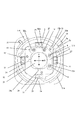
図2は固定ユニット2の正面図である。ここで、可動ユニット3の補正レンズ31とそれを支持する移動板32は破線で示している。固定ユニット2は、ベース部材である保持板(固定部材)21と保持板21に対して回転可能に支持された回転リング5が設けられている。保持板21には回転リング5をガイドするためのR状ガイド部21aが3箇所設けられている。回転リング5には略90°ごとに固定された4つの駆動コイル23を備え、駆動コイルの裏側、すなわち回転リング5側には磁性材料で形成された長方形のヨーク27が設けられている。保持板21には、可動ユニット3の位置を検出する2つのエンコーダ24が設けられている。なお、回転リング5は、不図示の手段により光軸方向への移動ができないように規制されている。また、固定ユニット2と可動ユニット3の間に配される3つのボール4を受けるボール受け部26を備えている。また回転リング5には内側に向かって突出する3箇所の突部5aが設けられている。
FIG. 1 is an exploded perspective view of a correction optical apparatus according to this embodiment. In FIG. 1, the correction optical device includes a fixed unit 2 fixed integrally with a photographing lens body (not shown), a movable unit 3 that includes a
FIG. 2 is a front view of the fixed unit 2. Here, the
R状ガイド部21aの1箇所にはボールプランジャ22が設けられ、回転リング5の回転位置の位置決めを行っている。この位置決め機構については図4を用いて説明する。ボールプランジャ22は内部のバネによって付勢されたボール22aが先端に露出しており、ボール22aが所定の押圧力で押されるとボール22aが引っ込み、押圧力がなくなると元の位置にボールが戻る。ボールプランジャ22の側面には雄ネジが形成されR状ガイド部21aに形成された雌ネジと係合している。41はナットでボールプランジャ22の位置決め後ナット41を締めることによりボールプランジャ22は固定される。
回転リング5には位置決め用の溝、5c、5dが形成されている。回転リングが図4(a)の位置に位置する場合には、ボールプランジャ22のボール22aが位置決め溝5cに嵌り込み回転リング5は図の回転位置にて位置決めされる。回転リング5に所定量以上のCCW方向(counterclockwise:反時計回り)への回転力が加わるとボール22aが位置決め溝5cの斜面に押され引っ込み、図4(b)に示すように回転リング5が回転する。図4(c)に示すように位置決め溝5dがボール22aの位置まで回転すると再度ボール22aがバネの付勢力にて押され位置決め溝5dに嵌り込む。この時に回転リング5に対する回転力がなくなると回転リング5は図4(c)の位置で位置決めされる。図4(a)の位置に戻す場合は、回転リング5にCW方向(clockwise:時計回り)への所定量以上の回転力を加えればよい。
A
The
図2、図3に示すように、回転リング5の回転位置を検出する検出手段として保持板21に取り付けられたフォトインタラプタ25と回転リング5の周面に形成された遮光板5bが設けられている。回転リング5が図4(a)および図4(c)の位置に位置する時には遮光板5bはフォトインタラプタ25の光を遮らないが、その間の位置、例えば図4(b)に示す位置に回転リング5がある場合には遮光板5bはフォトインタラプタ25の光を遮る。したがって、回転リング5に回転力を加えた後、フォトインタラプタ25より遮光されたとの信号が出れば回転リング5が回転を始めたことを検出でき、再度受光したとの信号がくれば所定の位置まで回転したことが検出できる。
As shown in FIGS. 2 and 3, a
保持板21には2か所の丸長穴21bがY方向に沿って直列に形成され、移動板32にはX方向に沿って2か所の丸長穴32cが直列に形成されている。保持板21と移動板32の間にはL字状のスライド板6が設けられている。スライド板6には各々2個ずつ(計4個)のベアリング8、10が回転自在に支持されている。ベアリング8は、それぞれ保持板21の丸長穴21bに嵌挿され、ベアリング10は保持板32の丸長穴32cに嵌挿されている。ベアリング8、10の直径は、丸長穴21b、32cの幅に対してほとんどガタはないが、長手方向に移動したときにベアリングの外周が回転できるように選択される。よって、スライド板6は保持板21に対してY方向にのみ移動可能で、移動板32はスライド板6に対してX方向にのみ移動可能となる。
以上説明した構成により、移動板32は保持板21に対してX方向およびY方向に並進移動可能であるが、回転力を受けても移動板32は保持板21に対して回転することはできない。
Two round
With the configuration described above, the moving
次に可動ユニット3は、画像ブレ補正を行う補正光学系31を保持している非磁性体の移動板32と駆動コイル23に対向して設けられた長方形状の永久磁石33を備えている。また、永久磁石33の裏側、すなわち移動板32側には閉磁路を形成するための磁性材料で形成されたバックヨーク35がそれぞれ設けられている。さらに移動板32には外側に向かって突出する3箇所の突部32aが設けられている。また、可動ユニット3は、エンコーダ24と対向の位置に配されたエンコーダスケール34を備えている。
永久磁石33、エンコーダスケール34、バックヨーク35は、それぞれ移動板32と一体に移動する。永久磁石33は図1に示すように中心線を境界に一方がN極、他方がS極となるように着磁されている。なお、永久磁石33、エンコーダスケール34は、可動ユニット3が可動範囲内で最大動いても固定ユニット2の駆動コイル23、エンコーダ24から外れることのない十分な大きさを有している。このように構成することにより、永久磁石33がヨーク27に及ぼす磁力で可動ユニット3は固定ユニット2側に吸着される。
ボール4は保持板21と移動板32との間に挟み込まれた状態で3つ配置されており、保持板21に配置されたボール受け部26の穴に納められている。ボール4は移動板32の移動とともにボール受け部26の穴の中で回転することで、移動板32を光軸と垂直な平面内で自在に移動させることができ、かつ、保持板21に対して常に一定の間隔となるように移動板32を支持している。
Next, the movable unit 3 includes a non-magnetic moving
The
Three balls 4 are arranged in a state of being sandwiched between the holding
次に、可動ユニット3の駆動方法について説明する。
図5は駆動部周辺の断面図である。図の状態では駆動コイル23の中心が永久磁石33の中心線上にある。永久磁石33の磁力は図5の矢印によって示すような磁力線を発生する。よって、駆動コイル23に図中右から左へ磁界を発生するように電流を流すと可動ユニット3を下方に移動させるような力が発生する。逆に電流を流すと可動ユニット3を上方に移動させるような力が発生する。4つの駆動コイル23にそれぞれ個別に電流を印加することで可動ユニット3は補正レンズの光軸と垂直な平面内での並進移動が可能となる。
次に、画像ブレ補正モード時のレンズ駆動ユニット1の制御方法について説明する。画像ブレ補正モード時には、まずカメラもしくはレンズ本体の不図示の振動検出センサから画像ブレ量が不図示のレンズ駆動ユニット用CPUに入力される。CPUは入力された画像ブレ量から画像ブレを補正するために必要な補正光学系の駆動量を算出し、それに基づいた駆動量を4つの駆動コイル23にそれぞれ駆動信号として出力する。駆動コイル23は出力信号に基づいて磁界を発生し、移動板32を光軸に垂直な平面内で並進移動する。移動板32の位置情報は、保持板21に設けられた2つのエンコーダ24がエンコーダスケール34を読み取ることで検出されてCPUにフィードバックされる。CPUはフィードバックされた位置情報と新たに振動検出センサから入力された画像ブレ量を基に補正光学系の駆動量を算出し、それに伴った駆動信号を駆動コイル23に出力する。以上の操作を繰り返し行うことでレンズ駆動ユニット1は画像ブレ補正を連続的に行う。
次に、可動ユニットのロック及びロック解除方法について図2、3を用いて説明する。まず、画像ブレ補正がオンの状態からオフ状態、すなわちロック状態に移行する動作を説明する。
図2は画像ブレ補正がオンの状態で、この時可動ユニット3は回転リング5にどこも接触していないため、光軸と垂直な平面内での並進運動が可能である。回転リング5はボールプランジャ22により図の位置に位置決めされているとともにボールプランジャ22の付勢力により片寄せされている。補正光学装置1がカメラもしくはレンズから画像ブレ補正オフの信号を受けるとCPUは各駆動コイル23に駆動信号を出力し、補正レンズ31の中心を光軸と略一致させた後、可動ユニット3に対してCW(時計回り)方向に回転力を加えるように駆動信号を与える。しかしながら、可動ユニット3は前述したように保持板21に対しては回転できないためその回転力の反力が駆動コイル23を支持する回転リング5に加わる。この時の回転力は、ボールプランジャ22のボール22aを付勢力に逆らって押し込むのに十分な回転力のため回転リング5はCCW(半時計回り)方向に回転する。
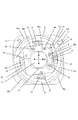
図3の位置まで回転リング5が回転したことをフォトインタラプタ25により検知すると、駆動コイル23への駆動信号を停止する。ボールプランジャ22のボール22aが位置決め溝5cに嵌り込むことにより回転リング5は図3の位置にて位置決めされる。その際、移動板32の突部32aに形成された凹部(係合部)32bに回転リング5の突部(規制部材)5aが係合することにより可動ユニット3はどの方向へも移動できなくなり、画像ブレ補正オフ状態、すなわちロック状態に移行する。
Next, a method for driving the movable unit 3 will be described.
FIG. 5 is a cross-sectional view around the drive unit. In the state shown in the figure, the center of the
Next, a method for controlling the
Next, a method for locking and unlocking the movable unit will be described with reference to FIGS. First, the operation of shifting from the on state to the off state, ie, the locked state, of the image blur correction will be described.
FIG. 2 shows a state in which the image blur correction is on. At this time, since the movable unit 3 is not in contact with any part of the
When the
続いて、ロック状態を解除する方法について説明する。ロックを解除し再び画像ブレ補正モードに戻る際には、図3のロック状態から各駆動コイル23に駆動信号を出力し、可動ユニット3に対してCCW方向に回転力を加えるように駆動信号を与える。しかしながら、可動ユニット3は前述したように保持板21に対しては回転できないためその回転力の反力が駆動コイル23を支持する回転リング5に加わる。この時の回転力は、ボールプランジャ22のボール22aを押し込むのに十分な回転力のため回転リング5はCW方向に回転する。図2の位置まで回転リング5が回転したことをフォトインタラプタ25により検知すると、駆動コイル23への駆動信号を停止する。ボールプランジャ22のボール22aが位置決め溝5dに嵌り込むことにより回転リング5は図2の位置にて位置決めされる。そして、回転リング5の突部5aの凹部32bとの係合を解いて可動部材の前記並進移動が可能な状態される。これにより、可動ユニット3と回転リング5はどこも接触せず、画像ブレ補正オン状態に戻る。
以上のようにして補正光学装置1は画像ブレ補正モードとなる。
Next, a method for releasing the lock state will be described. When releasing the lock and returning to the image blur correction mode again, a drive signal is output from the locked state of FIG. 3 to each
As described above, the correction
以上のような構成とすることで、補正レンズ駆動手段が回転リング(ロックリング)の回転駆動手段を兼ねることができるため、ロック専用の別の駆動手段を設けずに済む。そのため、低コスト、小型で消費電力を低減した補正光学装置を提供することができる。なお、以上説明した実施例では、駆動コイル23を回転リング5に固定し、永久磁石33を移動板32に固定したが、これとは逆に永久磁石を回転リング5に、駆動コイル23を移動板32に固定しても良い。
With the above-described configuration, the correction lens driving unit can also serve as the rotation driving unit of the rotating ring (lock ring), so that it is not necessary to provide another driving unit dedicated to the lock. Therefore, it is possible to provide a correction optical device that is low in cost, small in size, and low in power consumption. In the embodiment described above, the
[実施例2]
実施例2では、実施例1と駆動手段だけが異なる構成例について、図7を用いて説明する。実施例1では、駆動コイルと永久磁石とによって構成され、該永久磁石の発生する磁束を利用して電気エネルギーを機械エネルギーに変換するモータが用いられている。具体的には駆動コイル23と永久磁石33を用いた、いわゆるボイスコイルモータが駆動手段として用いられているが、本実施例では、ボイスコイルモータの代わりに振動波モータが用いられる。この振動波モータは、振動子に備えられた電気−機械エネルギー変換素子への駆動信号の印加により、節線が略直交する第一と第二の2つの曲げモードによる楕円運動を該振動子に励起し、該振動子との接触部に摩擦による駆動力を発生させるように構成されている。
[Example 2]
In the second embodiment, a configuration example in which only the driving unit is different from the first embodiment will be described with reference to FIG. In the first embodiment, a motor that includes a drive coil and a permanent magnet and converts electric energy into mechanical energy using a magnetic flux generated by the permanent magnet is used. Specifically, a so-called voice coil motor using the
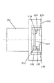
図7は振動波モータ71周りの断面図である。振動波モータ71は固定ユニット2と可動ユニット3の支持状態において、回転リング5に固定された板バネ72がたわんだ状態で移動板32に固定された摩擦板(摩擦部材)73に接触している。板バネ72がたわむことで振動波モータ71に設けられた二つの接触部74は図中A方向に常に板バネ72の付勢力を受けて摩擦板73に接触している。振動波モータ71の接触部74は、不図示の圧電素子(電気−機械エネルギー変換素子)を駆動することにより二つの振動モードが発生する。
一方は突き上げ方向(図中矢印A)に振動する突き上げモードで、他方は送り方向(図中矢印B)に振動する送りモードである。
これら二つの振動モードを組み合わせることで接触部74に楕円運動を発生させ、摩擦板73にはB方向に駆動力が伝えられる。4つの振動波モータ71が上記振動運動をそれぞれ個別に行うことで移動板32は光軸と垂直な平面内で並進運動する。また、4つの振動波モータ71が同方向に駆動力を与えることで、回転リング5が回転し、可動ユニット3をロックすることが可能になる。
FIG. 7 is a cross-sectional view around the
One is a push-up mode that vibrates in the push-up direction (arrow A in the figure), and the other is a feed mode that vibrates in the feed direction (arrow B in the figure).
By combining these two vibration modes, an elliptical motion is generated in the
[実施例3]
実施例1、2では撮像レンズの一部を構成する補正レンズを並進移動させることにより画像ぶれを防止する方式の撮像装置に本発明を適用したが、撮像素子を並進移動させることにより画像ぶれを防止する撮像装置においても、本発明は適用できる。
画像ぶれを防止する機能が、補正レンズから撮像素子に代わっている部分以外の構成は、実施例1、2と同様であるため、同じ部分に関しては説明を省略する。
[Example 3]
In the first and second embodiments, the present invention is applied to an image pickup apparatus that prevents image blurring by moving a correction lens that constitutes a part of the imaging lens. However, image blurring is prevented by moving the image sensor in translation. The present invention can also be applied to an imaging apparatus that prevents the above.
Since the configuration other than the part in which the function of preventing image blurring is replaced by the image pickup element from the correction lens is the same as that in the first and second embodiments, the description of the same part is omitted.
本実施例における撮像装置としてカメラ構成した際の例を、図8を用いて説明する。
161はレンズ鏡筒で、162はカメラボディである。また、101はカメラボディ162に内蔵された画像ぶれ補正装置である。
本実施例の画像ぶれ補正装置101は、撮像素子167と、撮像素子167を保持した移動板(可動部材)132と、移動板132を移動させる駆動装置を備える。移動板132は、実施例1と同様にX方向、Y方向にのみ並進移動可能に支持されている。
また、実施例1と同様に、補正光学装置101には、ベース部材である保持板(固定部材)と、保持板に対して回転可能に支持された回転リング105(回転部材)が設けられている。
駆動装置は、回転リング(回転部材)105に固定された4つの駆動コイル123と、移動板132に支持された4つの永久磁石133から構成されている(図8ではそのうちそれぞれ2個のみ図示)。
An example when a camera is configured as the imaging apparatus in the present embodiment will be described with reference to FIG.
The image
Similarly to the first embodiment, the correction
The driving device includes four driving
もちろん、本実施例においても実施例2のように駆動装置として振動波モータを用いることも可能である。
また、図8には示していないが、レンズ鏡筒1には、撮像光学系、カメラボディ162には振れを検出する加速度センサ、移動板132の2次元の移動を検出するエンコーダが設けられる。
さらに、駆動装置に電気エネルギーを供給する電源、加速度センサの信号とエンコーダの信号を処理して電源を操作する制御部が設けられる。
カメラボディ162内には撮像素子167がある。被写体からの光が、レンズ鏡筒101内のレンズを含む撮像光学系を透過し、撮像素子167に入射する。加速度センサの信号に基づき、画像ぶれ補正装置101により撮像素子167を移動させることで、画像の振れを補正するように構成されている。
撮像素子の移動に関しては、実施例1の補正レンズの移動と同様であり、上記駆動コイル123と永久磁石133からなる4つの駆動装置にそれぞれ駆動力を与えることで撮像素子167はレンズの光軸と垂直な平面内で並進運動する。
また、上記駆動装置に光軸周りに回転力を与えるように駆動力を与えると、移動板132は回転せず、反力により回転リング105が回転し、移動板132をロックすることが可能になる。位置決め機構やロック及びロック解除機構等は、実施例1と同様のため、説明を省略する。
Of course, also in this embodiment, it is possible to use a vibration wave motor as a driving device as in the second embodiment.
Although not shown in FIG. 8, the
In addition, a power source for supplying electric energy to the driving device and a control unit for operating the power source by processing the signal of the acceleration sensor and the signal of the encoder are provided.
There is an
The movement of the image pickup device is the same as the movement of the correction lens in the first embodiment. The
Further, when a driving force is applied to the driving device so as to apply a rotating force around the optical axis, the moving
本実施例によれば、撮像素子駆動手段が回転リング(ロックリング)の回転駆動手段を兼ねることができるため、ロック専用の別の駆動手段を設けずに済む。そのため、低コスト、小型で消費電力を低減した撮像装置を提供することができる。
さらに撮像素子を移動させる画像ぶれ補正装置では、撮像素子の移動を規制し固定するために撮像素子を回転させる訳にはいかないので、本発明の機構は好適である。
According to the present embodiment, the image sensor driving means can also serve as the rotation driving means of the rotating ring (lock ring), so that it is not necessary to provide another driving means dedicated to the lock. Therefore, it is possible to provide an imaging device that is low in cost, small in size, and low in power consumption.
Further, in the image blur correction apparatus that moves the image sensor, the mechanism of the present invention is suitable because the image sensor cannot be rotated to restrict and fix the movement of the image sensor.
[実施例4]
実施例1〜3ではカメラなどの撮像装置に本発明を適用したが、XYステージのような微動送り機構においても、本発明は適用できる。
例えば、生体試料などの観察に用いられる顕微鏡には、観察対象の任意位置を顕微鏡観察下に位置付けるため微動送り機構が用いられている。
このような微動送り機構において、本発明のように複数の駆動手段により可動部すなわち観察対象載置部を直接並進運動できることは、微動送り機構を薄くすることができ、顕微鏡全体の小型化、軽量化につながる。
[Example 4]
In the first to third embodiments, the present invention is applied to an imaging apparatus such as a camera. However, the present invention can also be applied to a fine movement feeding mechanism such as an XY stage.
For example, in a microscope used for observing a biological sample or the like, a fine movement feeding mechanism is used to position an arbitrary position of an observation target under the microscope observation.
In such a fine feed mechanism, the fact that the movable part, that is, the observation target mounting part can be directly translated by a plurality of driving means as in the present invention can make the fine feed mechanism thin, and the entire microscope can be reduced in size and weight. Leading to
一方、このような方式の微動送り機構では顕微鏡の運搬の際の衝撃などにより破損することを防止するために、観察対象載置部を固定するための位置規制機構を設けることが好ましい。
本発明を用いれば、このような微動送り機構の駆動手段と観察対象載置部を静止させるための位置規制機構の駆動手段を兼用することができる。
そのため、低コスト、小型で消費電力を低減した微動送り機構を提供することができる。
On the other hand, in such a fine movement feeding mechanism, it is preferable to provide a position restricting mechanism for fixing the observation target mounting portion in order to prevent damage due to an impact during transportation of the microscope.
If this invention is used, the drive means of such a fine movement feed mechanism and the drive means of the position control mechanism for making an observation object mounting part stand still can be combined.
Therefore, it is possible to provide a fine feed mechanism that is low in cost, small in size and low in power consumption.
1:補正光学装置
2:固定ユニット
3:可動ユニット
4:ボール
5:回転リング
5a:回転リングの突部
6:スライド板
8:ベアリング
10:ベアリング
21:保持板
23:駆動コイル
24:エンコーダ
25:フォトインタラプタ
26:ボール受け部
27:ヨーク
31:補正レンズ
32:移動板
33:永久磁石
34:エンコーダスケール
35:バックヨーク
1: correction optical device 2: fixed unit 3: movable unit 4: ball 5: rotating
Claims (29)
前記固定部材に対し前記補正レンズを光軸に垂直な平面内で並進移動可能に支持された可動部材と、
前記可動部材と前記回転部材との間に設けられた駆動手段と、
を備え、
前記駆動手段は、前記可動部材を前記固定部材に対し前記補正レンズの光軸に垂直な平面内で並進移動する方向に駆動可能に構成され、
前記駆動手段は、前記回転部材を前記補正レンズの光軸を中心に回転する方向に駆動して、前記回転部材に形成された規制部材を前記可動部材に形成された係合部に係合させることで、前記可動部材の前記並進移動を規制し、
前記駆動手段は、前記回転部材を前記補正レンズの光軸を中心に回転する方向に駆動して、前記規制部材の前記係合部との係合を解くことで、前記可動部材の前記並進移動を可能な状態にすることを特徴とする補正光学装置。 A fixing member that rotatably supports the rotating member in a plane perpendicular to the optical axis of the correction lens;
A movable member supported so that the correction lens can be translated in a plane perpendicular to the optical axis with respect to the fixed member;
Drive means provided between the movable member and the rotating member;
With
The drive means is configured to be able to drive the movable member in a direction that translates in a plane perpendicular to the optical axis of the correction lens with respect to the fixed member.
The driving means drives the rotating member in a direction rotating around the optical axis of the correction lens, and engages a regulating member formed on the rotating member with an engaging portion formed on the movable member. By restricting the translational movement of the movable member,
The driving means drives the rotating member in a direction rotating around the optical axis of the correction lens, and disengages the engaging member from the engaging portion, whereby the translational movement of the movable member is performed. A correction optical device characterized in that the correction optical device is in a possible state.
板部材と、
前記可動部材の前記板部材に対する回転を規制する第1のベアリングと、
前記板部材の前記固定部材に対する回転を規制する第2のベアリングと、
を有することを特徴とする請求項2または3に記載の補正光学装置。 The rotation regulating member is
A plate member;
A first bearing for restricting rotation of the movable member relative to the plate member;
A second bearing for restricting rotation of the plate member relative to the fixed member;
The correction optical apparatus according to claim 2, wherein:
前記固定部材に第2の開口が設けられ、
前記第1のベアリング及び前記第2のベアリングは、前記第1の開口及び前記第2の開口にそれぞれ挿入されていることを特徴とする請求項4に記載の補正光学装置。 A first opening is provided in the movable member;
A second opening is provided in the fixing member;
5. The correction optical apparatus according to claim 4, wherein the first bearing and the second bearing are inserted into the first opening and the second opening, respectively.
前記駆動コイルが前記回転部材に設けられ、前記永久磁石が前記可動部材に設けられて構成され、
または、前記駆動コイルが前記可動部材に設けられ、前記永久磁石が前記駆動コイルに設けられて構成されていることを特徴とする請求項1乃至5のいずれか1項に記載の補正光学装置。 The drive means includes a motor that is constituted by a drive coil and a permanent magnet, and converts electrical energy into mechanical energy using magnetic flux generated by the permanent magnet,
The drive coil is provided on the rotating member, and the permanent magnet is provided on the movable member.
The correction optical apparatus according to claim 1, wherein the driving coil is provided on the movable member, and the permanent magnet is provided on the driving coil.
前記可動部材又は前記回転部材に設けられた摩擦部材に、前記振動子の摩擦による駆動力が伝えられるように構成されていることを特徴とする請求項1乃至5のいずれか1項に記載の補正光学装置。 The driving means is provided with a vibrator provided with an electro-mechanical energy conversion element on the rotating member or the movable member,
6. The driving device according to claim 1, wherein a driving force generated by friction of the vibrator is transmitted to a friction member provided on the movable member or the rotating member. Correction optical device.
撮像素子を保持し、前記固定部材に対し前記光軸に垂直な平面内で並進移動可能に支持された可動部材と、
前記可動部材と前記回転部材との間に設けられた駆動手段と、
を備え、
前記駆動手段は、前記可動部材を前記固定部材に対し前記光軸に垂直な平面内で並進移動する方向に駆動可能に構成され、
前記駆動手段は、前記回転部材を前記光軸を中心に回転する方向に駆動して、前記回転部材に形成された規制部材を前記可動部材に形成された係合部に係合させることで、前記可動部材の前記並進移動を規制し、
前記駆動手段は、前記回転部材を前記光軸を中心に回転する方向に駆動して、前記規制部材の前記係合部との係合を解くことで、前記可動部材の前記並進移動を可能な状態にすることを特徴とする撮像装置。 A fixing member that rotatably supports the rotating member in a plane perpendicular to the optical axis of the lens;
A movable member that holds the image sensor and is supported so as to be able to translate in a plane perpendicular to the optical axis with respect to the fixed member;
Drive means provided between the movable member and the rotating member;
With
The drive means is configured to be able to drive the movable member in a direction that translates in a plane perpendicular to the optical axis with respect to the fixed member,
The driving means drives the rotating member in a direction rotating around the optical axis, and engages a restricting member formed on the rotating member with an engaging portion formed on the movable member, Restricting the translational movement of the movable member;
The drive means can drive the translational movement of the movable member by driving the rotating member in a direction rotating around the optical axis and releasing the engagement of the restricting member with the engaging portion. An imaging device characterized by being in a state.
板部材と、
前記可動部材の前記板部材に対する回転を規制する第1のベアリングと、
前記板部材の前記固定部材に対する回転を規制する第2のベアリングと、
を有することを特徴とする請求項11または12に記載の撮像装置。 The rotation regulating member is
A plate member;
A first bearing for restricting rotation of the movable member relative to the plate member;
A second bearing for restricting rotation of the plate member relative to the fixed member;
The imaging apparatus according to claim 11, wherein the imaging apparatus includes:
前記固定部材に第2の開口が設けられ、
前記第1のベアリング及び前記第2のベアリングは、前記第1の開口及び前記第2の開口にそれぞれ挿入されていることを特徴とする請求項13に記載の撮像装置。 A first opening is provided in the movable member;
A second opening is provided in the fixing member;
The imaging device according to claim 13, wherein the first bearing and the second bearing are inserted into the first opening and the second opening, respectively.
または、前記駆動コイルが前記可動部材に設けられ、前記永久磁石が前記駆動コイルに設けられて構成されていることを特徴とする請求項10乃至14のいずれか1項に記載の撮像装置。 The driving means includes a driving coil and a permanent magnet, and includes a motor that converts electric energy into mechanical energy using magnetic flux generated by the permanent magnet, and the driving coil is provided in the rotating member, A permanent magnet is provided on the movable member;
The imaging device according to claim 10, wherein the drive coil is provided on the movable member, and the permanent magnet is provided on the drive coil.
前記可動部材又は前記回転部材に設けられた摩擦部材に、前記振動子の摩擦による駆動力が伝えられるように構成されていることを特徴とする請求項16に記載の撮像装置。 A vibrator provided with the electromechanical energy conversion element is provided on the rotating member or the movable member,
The imaging apparatus according to claim 16, wherein a driving force due to friction of the vibrator is transmitted to a friction member provided on the movable member or the rotating member.
前記固定部材によって第1の面内で回転可能に支持され、規制部材を有する回転部材と、
前記規制部材と係合可能に構成された係合部を有し、前記固定部材に対し前記第1の面に平行な第2の面内で移動可能に構成された可動部材と、
前記可動部材と前記回転部材との間に設けられた駆動手段と、
を備え、
前記駆動手段は、第1の状態で、前記可動部材を前記固定部材に対し前記第2の面内で移動する方向に駆動可能に構成され、
前記駆動手段は、第2の状態で、前記回転部材を前記第1の面と交差する軸回りに回転駆動可能に構成され、前記回転部材は前記第2の状態において、前記固定部材及び前記可動部材に対して回転可能に構成されていることを特徴とする装置。 A fixing member;
A rotating member that is rotatably supported in the first plane by the fixing member and has a regulating member;
A movable member configured to be movable in a second plane parallel to the first surface with respect to the fixed member;
Drive means provided between the movable member and the rotating member;
With
The driving means is configured to be able to drive the movable member in the first state in a direction in which the movable member moves in the second plane with respect to the fixed member,
The driving means is configured to be able to rotate the rotating member around an axis intersecting the first surface in the second state, and the rotating member is configured to move the fixed member and the movable member in the second state. An apparatus configured to be rotatable with respect to a member.
板部材と、
前記可動部材の前記板部材に対する回転を規制する第1のベアリングと、
前記板部材の前記固定部材に対する回転を規制する第2のベアリングと、
を有することを特徴とする請求項20または21に記載の装置。 The rotation regulating member is
A plate member;
A first bearing for restricting rotation of the movable member relative to the plate member;
A second bearing for restricting rotation of the plate member relative to the fixed member;
The device according to claim 20 or 21, characterized by comprising:
前記固定部材に第2の開口が設けられ、
前記第1のベアリング及び前記第2のベアリングは、前記第1の開口及び前記第2の開口にそれぞれ挿入されていることを特徴とする請求項22に記載の装置。 A first opening is provided in the movable member;
A second opening is provided in the fixing member;
23. The apparatus of claim 22, wherein the first bearing and the second bearing are inserted into the first opening and the second opening, respectively.
前記可動部材又は前記回転部材に設けられた摩擦部材に、前記振動子の摩擦による駆動力が伝えられるように構成されていることを特徴とする請求項25に記載の装置。 A vibrator provided with the electromechanical energy conversion element is provided on the rotating member or the movable member,
26. The apparatus according to claim 25, wherein a driving force due to friction of the vibrator is transmitted to a friction member provided on the movable member or the rotating member.
Priority Applications (2)
| Application Number | Priority Date | Filing Date | Title |
|---|---|---|---|
| JP2012154364A JP6103840B2 (en) | 2011-07-28 | 2012-07-10 | Correction optical apparatus and imaging apparatus |
| US13/556,857 US9348150B2 (en) | 2011-07-28 | 2012-07-24 | Correcting optical device and image pickup apparatus |
Applications Claiming Priority (3)
| Application Number | Priority Date | Filing Date | Title |
|---|---|---|---|
| JP2011165401 | 2011-07-28 | ||
| JP2011165401 | 2011-07-28 | ||
| JP2012154364A JP6103840B2 (en) | 2011-07-28 | 2012-07-10 | Correction optical apparatus and imaging apparatus |
Publications (3)
| Publication Number | Publication Date |
|---|---|
| JP2013047787A JP2013047787A (en) | 2013-03-07 |
| JP2013047787A5 JP2013047787A5 (en) | 2015-08-27 |
| JP6103840B2 true JP6103840B2 (en) | 2017-03-29 |
Family
ID=47910884
Family Applications (1)
| Application Number | Title | Priority Date | Filing Date |
|---|---|---|---|
| JP2012154364A Active JP6103840B2 (en) | 2011-07-28 | 2012-07-10 | Correction optical apparatus and imaging apparatus |
Country Status (2)
| Country | Link |
|---|---|
| US (1) | US9348150B2 (en) |
| JP (1) | JP6103840B2 (en) |
Families Citing this family (44)
| Publication number | Priority date | Publication date | Assignee | Title |
|---|---|---|---|---|
| CN113472989A (en) | 2012-11-28 | 2021-10-01 | 核心光电有限公司 | Multi-aperture imaging system and method for acquiring images by multi-aperture imaging system |
| JP6053535B2 (en) * | 2013-01-25 | 2016-12-27 | キヤノン株式会社 | Correction optical device, image shake correction device, and imaging device |
| CN108769497B (en) | 2013-06-13 | 2021-01-15 | 核心光电有限公司 | Double-aperture zooming digital camera |
| JP6372054B2 (en) * | 2013-06-20 | 2018-08-15 | リコーイメージング株式会社 | LOCK MECHANISM AND OPTICAL DEVICE HAVING THE SAME |
| CN105359006B (en) | 2013-07-04 | 2018-06-22 | 核心光电有限公司 | Small-sized focal length lens external member |
| CN109120823B (en) | 2013-08-01 | 2020-07-14 | 核心光电有限公司 | Thin multi-aperture imaging system with auto-focus and method of use thereof |
| US9964778B2 (en) | 2013-10-25 | 2018-05-08 | Jahwa Electronics Co., Ltd. | Camera lens module |
| US10133086B2 (en) | 2013-10-25 | 2018-11-20 | Jahwa Electronics Co., Ltd. | Camera lens module |
| WO2015060637A1 (en) | 2013-10-25 | 2015-04-30 | 자화전자(주) | Camera lens module |
| US9392188B2 (en) | 2014-08-10 | 2016-07-12 | Corephotonics Ltd. | Zoom dual-aperture camera with folded lens |
| CN112433331B (en) | 2015-01-03 | 2022-07-08 | 核心光电有限公司 | Miniature telephoto lens module and camera using the same |
| CN111175935B (en) | 2015-04-16 | 2022-02-08 | 核心光电有限公司 | Auto-focus and optical image stabilization in compact folded cameras |
| US10036895B2 (en) | 2015-05-28 | 2018-07-31 | Corephotonics Ltd. | Bi-directional stiffness for optical image stabilization in a dual-aperture digital camera |
| US10230898B2 (en) | 2015-08-13 | 2019-03-12 | Corephotonics Ltd. | Dual aperture zoom camera with video support and switching / non-switching dynamic control |
| JP2017073890A (en) | 2015-10-07 | 2017-04-13 | キヤノン株式会社 | Translation drive unit, image blur correction device, barrel and imaging device |
| EP4024842A3 (en) | 2015-12-29 | 2022-08-31 | Corephotonics Ltd. | Dual-aperture zoom digital camera with automatic adjustable tele field of view |
| JP6518960B2 (en) * | 2016-03-10 | 2019-05-29 | パナソニックIpマネジメント株式会社 | Correction optical device and imaging device |
| US10488631B2 (en) * | 2016-05-30 | 2019-11-26 | Corephotonics Ltd. | Rotational ball-guided voice coil motor |
| WO2017221106A1 (en) | 2016-06-19 | 2017-12-28 | Corephotonics Ltd. | Frame synchronization in a dual-aperture camera system |
| WO2018007951A1 (en) | 2016-07-07 | 2018-01-11 | Corephotonics Ltd. | Dual-camera system with improved video smooth transition by image blending |
| KR102226315B1 (en) | 2016-07-07 | 2021-03-12 | 코어포토닉스 리미티드 | Linear ball guided voice coil motor for folded optic |
| JP2018074723A (en) * | 2016-10-27 | 2018-05-10 | セイコーエプソン株式会社 | Drive device, piezoelectric motor, robot, electronic component transfer device, and printer |
| EP4246993A3 (en) | 2016-12-28 | 2024-03-06 | Corephotonics Ltd. | Folded camera structure with an extended light-folding-element scanning range |
| KR102365926B1 (en) | 2017-01-12 | 2022-02-23 | 코어포토닉스 리미티드 | Compact folded camera |
| KR102530535B1 (en) | 2017-03-15 | 2023-05-08 | 코어포토닉스 리미티드 | Cameras with panoramic scanning range |
| US10904512B2 (en) | 2017-09-06 | 2021-01-26 | Corephotonics Ltd. | Combined stereoscopic and phase detection depth mapping in a dual aperture camera |
| US10951834B2 (en) | 2017-10-03 | 2021-03-16 | Corephotonics Ltd. | Synthetically enlarged camera aperture |
| CN113075837B (en) | 2017-11-23 | 2022-04-12 | 核心光电有限公司 | Camera, manufacturing method thereof, mobile electronic equipment and method for reducing space occupied by bulges |
| EP3848749A1 (en) | 2018-02-05 | 2021-07-14 | Corephotonics Ltd. | Reduced height penalty for folded camera |
| EP4191315A1 (en) | 2018-02-12 | 2023-06-07 | Corephotonics Ltd. | Folded camera with optical image stabilization |
| US10694168B2 (en) | 2018-04-22 | 2020-06-23 | Corephotonics Ltd. | System and method for mitigating or preventing eye damage from structured light IR/NIR projector systems |
| KR102299752B1 (en) | 2018-04-23 | 2021-09-08 | 코어포토닉스 리미티드 | Optical path folding element with extended two-degree-of-freedom rotation range |
| US11363180B2 (en) | 2018-08-04 | 2022-06-14 | Corephotonics Ltd. | Switchable continuous display information system above camera |
| US11635596B2 (en) | 2018-08-22 | 2023-04-25 | Corephotonics Ltd. | Two-state zoom folded camera |
| KR102242437B1 (en) | 2019-01-07 | 2021-04-20 | 코어포토닉스 리미티드 | Rotating mechanism with sliding joint |
| EP3782363B1 (en) | 2019-03-09 | 2023-06-07 | Corephotonics Ltd. | Method for dynamic stereoscopic calibration |
| KR102254947B1 (en) | 2019-07-31 | 2021-05-24 | 코어포토닉스 리미티드 | System and method for generating background blur in camera panning or motion |
| US11659135B2 (en) | 2019-10-30 | 2023-05-23 | Corephotonics Ltd. | Slow or fast motion video using depth information |
| EP4049444A4 (en) | 2019-12-09 | 2022-11-16 | Corephotonics Ltd. | Systems and methods for obtaining a smart panoramic image |
| WO2021220080A1 (en) | 2020-04-26 | 2021-11-04 | Corephotonics Ltd. | Temperature control for hall bar sensor correction |
| KR102495627B1 (en) | 2020-05-17 | 2023-02-06 | 코어포토닉스 리미티드 | Image stitching in the presence of a full-field reference image |
| EP3966631B1 (en) | 2020-05-30 | 2023-01-25 | Corephotonics Ltd. | Systems and methods for obtaining a super macro image |
| US11637977B2 (en) | 2020-07-15 | 2023-04-25 | Corephotonics Ltd. | Image sensors and sensing methods to obtain time-of-flight and phase detection information |
| KR20230004887A (en) | 2020-07-15 | 2023-01-06 | 코어포토닉스 리미티드 | Point of view aberrations correction in a scanning folded camera |
Family Cites Families (14)
| Publication number | Priority date | Publication date | Assignee | Title |
|---|---|---|---|---|
| JP3397536B2 (en) * | 1995-08-21 | 2003-04-14 | キヤノン株式会社 | Correction optics |
| JP4403609B2 (en) | 1998-12-11 | 2010-01-27 | 株式会社ニコン | Blur correction device and optical device |
| JP4011576B2 (en) | 2004-10-20 | 2007-11-21 | 株式会社タムロン | Actuator and lens unit and camera provided with the same |
| JP4576214B2 (en) * | 2004-11-26 | 2010-11-04 | オリンパスイメージング株式会社 | Ultrasonic motor and lens barrel |
| JP4498265B2 (en) * | 2005-11-15 | 2010-07-07 | キヤノン株式会社 | Motor drive device, control method, and program |
| JP4336698B2 (en) * | 2006-06-13 | 2009-09-30 | 株式会社タムロン | Actuator, lens unit and camera equipped with the same |
| JP2008070613A (en) | 2006-09-14 | 2008-03-27 | Tamron Co Ltd | Actuator, lens unit equipped with the same, and camera |
| JP4483869B2 (en) * | 2007-02-01 | 2010-06-16 | ソニー株式会社 | Image blur correction device, lens barrel, and imaging device |
| JP4973244B2 (en) * | 2007-03-07 | 2012-07-11 | カシオ計算機株式会社 | Reference position holding device for image stabilization mechanism |
| JP2008304850A (en) * | 2007-06-11 | 2008-12-18 | Tamron Co Ltd | Actuator, and lens unit equipped therewith and camera |
| JP2009217202A (en) * | 2008-03-13 | 2009-09-24 | Nikon Corp | Optical apparatus and optical equipment |
| JP2010128385A (en) | 2008-11-28 | 2010-06-10 | Panasonic Corp | Shake correction device |
| JP5495860B2 (en) | 2010-03-03 | 2014-05-21 | キヤノン株式会社 | Optical image stabilizer and optical apparatus |
| JP2011242680A (en) | 2010-05-20 | 2011-12-01 | Kenkotokina Corp | Camera shake correction unit |
-
2012
- 2012-07-10 JP JP2012154364A patent/JP6103840B2/en active Active
- 2012-07-24 US US13/556,857 patent/US9348150B2/en active Active
Also Published As
| Publication number | Publication date |
|---|---|
| JP2013047787A (en) | 2013-03-07 |
| US9348150B2 (en) | 2016-05-24 |
| US20130076922A1 (en) | 2013-03-28 |
Similar Documents
| Publication | Publication Date | Title |
|---|---|---|
| JP6103840B2 (en) | Correction optical apparatus and imaging apparatus | |
| JP6108801B2 (en) | Correction optical device, image shake correction device, and imaging device | |
| JP6053535B2 (en) | Correction optical device, image shake correction device, and imaging device | |
| JP5725841B2 (en) | Correction optical device | |
| US8582205B2 (en) | Lens barrel and optical apparatus including the same | |
| KR20130069406A (en) | Image stabilization apparatus, optical apparatus, and imaging apparatus | |
| JP2008045919A (en) | Position detection device, blur correcting device, lens barrel, and optical equipment | |
| JP2012203319A (en) | Correction apparatus for image blurring and imaging apparatus | |
| JP2011102887A (en) | Lens-driving device | |
| JP2012215650A (en) | Image blur correction device, optical instrument and imaging apparatus | |
| US20110181743A1 (en) | Imaging device | |
| JP2010087982A (en) | Image capturing unit and image capturing apparatus | |
| JP2013097168A (en) | Lens drive unit, lens device with the same, and imaging apparatus | |
| JP2017037182A (en) | Image blur correction device, lens barrel, and imaging apparatus | |
| US10038848B2 (en) | Image blur correction device and imaging device | |
| TWI440886B (en) | Actuator and camera module | |
| JP2013125228A (en) | Image blur correcting device, optical device including the same, and imaging device | |
| JP2013125228A5 (en) | ||
| JP6331319B2 (en) | Optical equipment | |
| JP2018124586A (en) | Optical instrument | |
| JP2011158738A (en) | Optical apparatus | |
| JP2014092563A (en) | Lens frame | |
| JP2014164062A (en) | Lens barrel | |
| JP2013025259A (en) | Position control device of retreating optical element | |
| JP2018036370A (en) | Translational drive device and electronic apparatus |
Legal Events
| Date | Code | Title | Description |
|---|---|---|---|
| RD01 | Notification of change of attorney |
Free format text: JAPANESE INTERMEDIATE CODE: A7421 Effective date: 20131212 |
|
| A521 | Request for written amendment filed |
Free format text: JAPANESE INTERMEDIATE CODE: A523 Effective date: 20150710 |
|
| A621 | Written request for application examination |
Free format text: JAPANESE INTERMEDIATE CODE: A621 Effective date: 20150710 |
|
| A977 | Report on retrieval |
Free format text: JAPANESE INTERMEDIATE CODE: A971007 Effective date: 20160531 |
|
| A131 | Notification of reasons for refusal |
Free format text: JAPANESE INTERMEDIATE CODE: A131 Effective date: 20160607 |
|
| A521 | Request for written amendment filed |
Free format text: JAPANESE INTERMEDIATE CODE: A523 Effective date: 20160802 |
|
| A131 | Notification of reasons for refusal |
Free format text: JAPANESE INTERMEDIATE CODE: A131 Effective date: 20161115 |
|
| A521 | Request for written amendment filed |
Free format text: JAPANESE INTERMEDIATE CODE: A523 Effective date: 20170113 |
|
| TRDD | Decision of grant or rejection written | ||
| A01 | Written decision to grant a patent or to grant a registration (utility model) |
Free format text: JAPANESE INTERMEDIATE CODE: A01 Effective date: 20170131 |
|
| A61 | First payment of annual fees (during grant procedure) |
Free format text: JAPANESE INTERMEDIATE CODE: A61 Effective date: 20170228 |
|
| R151 | Written notification of patent or utility model registration |
Ref document number: 6103840 Country of ref document: JP Free format text: JAPANESE INTERMEDIATE CODE: R151 |