JP2013143753A - Imaging apparatus - Google Patents
Imaging apparatus Download PDFInfo
- Publication number
- JP2013143753A JP2013143753A JP2012004358A JP2012004358A JP2013143753A JP 2013143753 A JP2013143753 A JP 2013143753A JP 2012004358 A JP2012004358 A JP 2012004358A JP 2012004358 A JP2012004358 A JP 2012004358A JP 2013143753 A JP2013143753 A JP 2013143753A
- Authority
- JP
- Japan
- Prior art keywords
- optical system
- focal length
- optical
- image
- center
- Prior art date
- Legal status (The legal status is an assumption and is not a legal conclusion. Google has not performed a legal analysis and makes no representation as to the accuracy of the status listed.)
- Pending
Links
- 238000003384 imaging method Methods 0.000 title claims abstract description 71
- 230000003287 optical effect Effects 0.000 claims abstract description 281
- 230000008859 change Effects 0.000 claims description 37
- 230000014509 gene expression Effects 0.000 claims description 10
- 238000010586 diagram Methods 0.000 description 8
- 238000000034 method Methods 0.000 description 7
- 230000000694 effects Effects 0.000 description 4
- 230000008569 process Effects 0.000 description 4
- 210000001747 pupil Anatomy 0.000 description 4
- 230000009467 reduction Effects 0.000 description 3
- 230000003247 decreasing effect Effects 0.000 description 2
- 238000005549 size reduction Methods 0.000 description 2
- 230000015556 catabolic process Effects 0.000 description 1
- 230000000295 complement effect Effects 0.000 description 1
- 238000006731 degradation reaction Methods 0.000 description 1
- 230000006866 deterioration Effects 0.000 description 1
- 230000010365 information processing Effects 0.000 description 1
- CNQCVBJFEGMYDW-UHFFFAOYSA-N lawrencium atom Chemical compound [Lr] CNQCVBJFEGMYDW-UHFFFAOYSA-N 0.000 description 1
- 230000007246 mechanism Effects 0.000 description 1
- 238000012986 modification Methods 0.000 description 1
- 230000004048 modification Effects 0.000 description 1
- 230000002093 peripheral effect Effects 0.000 description 1
- 239000013589 supplement Substances 0.000 description 1
- 238000009966 trimming Methods 0.000 description 1
Images


Classifications
-
- H—ELECTRICITY
- H04—ELECTRIC COMMUNICATION TECHNIQUE
- H04N—PICTORIAL COMMUNICATION, e.g. TELEVISION
- H04N5/00—Details of television systems
- H04N5/222—Studio circuitry; Studio devices; Studio equipment
- H04N5/262—Studio circuits, e.g. for mixing, switching-over, change of character of image, other special effects ; Cameras specially adapted for the electronic generation of special effects
-
- H—ELECTRICITY
- H04—ELECTRIC COMMUNICATION TECHNIQUE
- H04N—PICTORIAL COMMUNICATION, e.g. TELEVISION
- H04N23/00—Cameras or camera modules comprising electronic image sensors; Control thereof
- H04N23/60—Control of cameras or camera modules
- H04N23/69—Control of means for changing angle of the field of view, e.g. optical zoom objectives or electronic zooming
Landscapes
- Engineering & Computer Science (AREA)
- Multimedia (AREA)
- Signal Processing (AREA)
- Studio Devices (AREA)
- Structure And Mechanism Of Cameras (AREA)
- Indication In Cameras, And Counting Of Exposures (AREA)
Abstract
Description
本発明は、撮像装置に関するものである。 The present invention relates to an imaging apparatus.
小型情報端末機に搭載される光学系は、小型、特に薄型であることが要求されている。また、レンズを交換することなく、広いズーム範囲も要求されている。
このため、複数の光学系を有し、ズームを行うことで、広いズーム範囲でも、撮影範囲における画素数の低下を防いで、小型化を図っている構成が提案されている。さらに、複数の光学系を円滑に切り替えできるように、ズームにより異なる光学系間で画角の重複を持たせるなどの対策がなされている。
An optical system mounted on a small information terminal is required to be small, particularly thin. Also, a wide zoom range is required without changing the lens.
For this reason, a configuration has been proposed in which a plurality of optical systems are provided and zooming is performed to prevent a reduction in the number of pixels in the shooting range even in a wide zoom range and to reduce the size. Further, in order to smoothly switch between a plurality of optical systems, measures are taken such as overlapping the angle of view between different optical systems by zooming.
例えば、以下の特許文献1においては、2つの固定焦点の光学系を電子ズームにより一連のズームのようにしている。そして、トリミングで画質劣化を抑制している。
また、例えば、特許文献2では、光学ズームと電子ズームとを併用し、ズームインとズームアウトで光学系の切り替えポイントを変え、光学系の切り替え回数を低減する構成が提案されている。
さらに、例えば、以下の特許文献3では、光学ズームと電子ズームとの切り替えにおいて、固定焦点距離レンズの焦点距離とズームレンズの最小焦点距離との間の焦点距離ギャップを、固定焦点距離レンズで得られたデジタル画像の電子ズームで補間している。
For example, in
For example,
Further, for example, in Patent Document 3 below, in switching between optical zoom and electronic zoom, a focal length gap between the focal length of the fixed focal length lens and the minimum focal length of the zoom lens is obtained by the fixed focal length lens. The digital image is interpolated by electronic zoom.
複数の光学系を有する装置では、各光学系の光軸が一致していない。このため、光学系の切り替え時に撮影範囲が大きくシフトしてしまう。この結果、使用者に不自然な印象を与えてしまう。また、撮影範囲のシフトに起因して、撮影範囲内に存在していた被写体が、突然撮影範囲外に移動してしまい、使用者が被写体を見失う可能性がある。特に望遠端側では撮影範囲が狭いので、撮影範囲のシフトによる被写体を見失う影響が大きい。 In an apparatus having a plurality of optical systems, the optical axes of the optical systems do not match. For this reason, the photographing range is greatly shifted when the optical system is switched. As a result, an unnatural impression is given to the user. Also, due to the shift of the shooting range, the subject that was present in the shooting range may suddenly move out of the shooting range, and the user may lose sight of the subject. In particular, since the shooting range is narrow on the telephoto end side, the influence of losing the subject due to the shift of the shooting range is great.
特許文献1、2、3のいずれの文献も、複数の光学系の切り替えがスムーズになるように画角の変化を抑制している構成のみ開示している。このため、光学系を切り替えたときに生ずる撮影範囲のシフトに関しては一切対応していない。
Each of
換言すると、従来の構成において、光学系を切り替えながら、撮影範囲を大きくする、または撮影範囲を小さくすると、円滑な連続した撮影範囲の変化が起きず、撮影範囲が突然シフト(画像の飛び)してしまうという課題がある。 In other words, in the conventional configuration, if the shooting range is enlarged or the shooting range is reduced while switching the optical system, the continuous shooting range does not change smoothly and the shooting range is suddenly shifted (image skipping). There is a problem that it ends up.
本発明は、上記に鑑みてなされたものであって、広いズーム範囲にわたって撮影範囲のシフトを低減できる撮像装置を提供することを目的とする。 The present invention has been made in view of the above, and an object of the present invention is to provide an imaging apparatus capable of reducing a shift of a shooting range over a wide zoom range.
上述した課題を解決し、目的を達成するために、本発明の撮像装置は、
異なる焦点距離を有する複数の光学系と、
光学系により被写体を撮像する撮像素子と、
複数の光学系の少なくとも一つの光学系による出力画像の画角を変化させるズーム制御部と、を有し、
変化する画角の一部が、他の光学系の画角と同じであり、
さらに、
ズーム時の表示画像の中心位置を、画角の一部が同じである他の光学系の光軸中心(光学中心)に向かって変化させる制御部を有することを特徴とする。
In order to solve the above-described problems and achieve the object, the imaging apparatus of the present invention includes:
A plurality of optical systems having different focal lengths;
An image sensor for imaging a subject with an optical system;
A zoom control unit that changes an angle of view of an output image by at least one of the plurality of optical systems, and
Part of the changing angle of view is the same as the angle of view of other optical systems,
further,
It has a control part which changes the center position of the display image at the time of zooming toward the optical axis center (optical center) of other optical systems in which a part of angle of view is the same.
本発明によれば、撮像範囲のシフトを防止できる撮像装置を提供できるという効果を奏する。 According to the present invention, there is an effect that it is possible to provide an imaging device capable of preventing a shift of the imaging range.
本実施形態の撮像装置の構成による作用効果を説明する。なお、この実施形態によって本発明は限定されるものではない。すなわち、実施形態の説明に当たって、例示のために特定の詳細な内容が多く含まれるが、これらの詳細な内容に色々なバリエーションや変更を加えても、本発明の範囲を超えない。従って、以下で説明する本発明の例示的な実施形態は、権利請求された発明に対して、一般性を失わせることなく、また、何ら限定をすることもなく、述べられたものである。 The effects of the configuration of the imaging apparatus according to the present embodiment will be described. In addition, this invention is not limited by this embodiment. That is, in describing the embodiment, a lot of specific details are included for the purpose of illustration, but various variations and modifications may be added to these details without exceeding the scope of the present invention. Accordingly, the exemplary embodiments of the present invention described below are set forth without loss of generality or limitation to the claimed invention.
図1は、実施形態に係る撮像装置100の機能ブロックを示す図である。撮像装置100の機能の詳細は後述する。
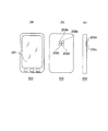
図2(a)は、撮像装置の例である携帯電話200を正面から見た図、図2(b)は、携帯電話200を裏面から見た図、図2(c)は、側面図である。
FIG. 1 is a diagram illustrating functional blocks of the
2A is a view of a
図2(a)において、表示部201は、後述する光学系で撮像した画像を表示する。図2(b)において、携帯電話200は、異なる焦点距離を有する複数、本例では4つの光学系202a、202b、202c、202dを有している。なお、携帯電話200は、PHS、スマートフォン、PDA等の携帯情報処理装置であってもよい。
In FIG. 2A, the
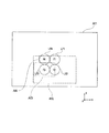
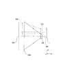
図3は、複数(n=4)の光学系Lf1、Lf2、Lf3、Lf4の配置と、その撮影範囲を示す図である。図3は、使用者が撮像素子I(102)側から被写体を撮影する方向を見た図とする。
例えば、4つの光学系Lf1、Lf2、Lf3、Lf4は、図2に示す4つの光学系202a、202b、202c、202dに対応する。
FIG. 3 is a diagram showing the arrangement of a plurality (n = 4) of optical systems Lf1, Lf2, Lf3, and Lf4 and the photographing range thereof. FIG. 3 is a diagram in which the user looks in the direction in which the subject is photographed from the image sensor I (102) side.
For example, the four optical systems Lf1, Lf2, Lf3, and Lf4 correspond to the four
光学系Lf1は、焦点距離f1を有する。光学系Lf2は、焦点距離f2を有する。光学系Lf3は、焦点距離f3を有する。光学系Lf4は、焦点距離f4を有する。
また、焦点距離の長さは、以下の関係を有している。
f1<f2<f3<f4
Optics Lf1 has a focal length f 1. Optics Lf2 has a focal length f 2. Optics Lf3 has a focal length f 3. Optics Lf4 has a focal length f 4.
Further, the length of the focal length has the following relationship.
f 1 <f 2 <f 3 <f 4
Af1は、光学系Lflの撮影範囲である。Af2は、光学系Lf2の撮影範囲である。Af3は、光学系Lf3の撮影範囲である。Af4は、光学系Lf4の撮影範囲である。 Af1 is a photographing range of the optical system Lfl. Af2 is a photographing range of the optical system Lf2. Af3 is a photographing range of the optical system Lf3. Af4 is a photographing range of the optical system Lf4.
図3から明らかなように、光学系の焦点距離がf1からf4へ長くなるにしたがって、撮影範囲はAf1からAf4へと狭くなる。 As is clear from FIG. 3, as the focal length of the optical system increases from f 1 to f 4 , the imaging range becomes narrower from Af 1 to Af 4 .
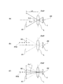
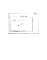
次に、実施形態における「画角」について説明する。まず、図4(a)は、一般的な画角の定義を説明する図である。
図4(a)において、表示範囲A1(対角)の直径(入射窓の大きさ)が光学系Lの入射瞳ENPの中心に対して張る角度2ωを画角という。また、図4(a)において、光学系Lは、光軸AXを有する。撮像素子Iは、被写体像を撮像する。
Next, “view angle” in the embodiment will be described. First, FIG. 4A is a diagram for explaining a general definition of the angle of view.
In FIG. 4A, an angle 2ω at which the diameter of the display range A1 (diagonal) (the size of the entrance window) extends with respect to the center of the entrance pupil ENP of the optical system L is referred to as an angle of view. In FIG. 4A, the optical system L has an optical axis AX. The image sensor I captures a subject image.
次に、図4(b)に示すように、表示範囲A2(対角)は、光軸AXより変化した位置に中心軸AX2を有する。そして、図4(c)に示すように、表示範囲A2の中心軸AX2を図中下方に変化させて、中心軸AX2と入射瞳ENPの中心(光軸AXと交点)とを疑似的に一致させる。このとき、表示範囲A1(対角)の直径(入射窓の大きさ)が光学系Lの入射瞳ENPの中心に対して張る角度2ω’も本実施形態では「画角」という。
なお、「撮影範囲」とは、撮像装置が撮影した範囲をいう。「表示範囲」とは、電子ズームの場合は撮影範囲から切り取って、表示する範囲をいい、光学ズームの場合は撮影範囲と同じ範囲をいう。
さらに、「シフト」とは、範囲の移動をいう。「変化」とは、軸または位置の変化をいう。
Next, as shown in FIG. 4B, the display range A2 (diagonal) has a central axis AX2 at a position changed from the optical axis AX. Then, as shown in FIG. 4C, the center axis AX2 of the display range A2 is changed downward in the figure, and the center axis AX2 and the center of the entrance pupil ENP (intersection point with the optical axis AX) are artificially matched. Let At this time, the angle 2ω ′ at which the diameter of the display range A1 (diagonal) (the size of the incident window) extends with respect to the center of the entrance pupil ENP of the optical system L is also referred to as “view angle” in the present embodiment.
The “shooting range” refers to a range shot by the imaging apparatus. The “display range” refers to a range that is cut out from the shooting range in the case of electronic zoom and displayed, and in the case of optical zoom, it refers to the same range as the shooting range.
Further, “shift” refers to movement of a range. “Change” refers to a change in axis or position.
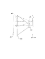
図5は、4つの光学系のうち、光学系Lf2、Lf3を図3の下側からy方向を見た断面構成図である。ここで、上述したように、光学系Lf2の焦点距離f2よりも、光学系Lf3の焦点距離f3のほうが長い構成である。 FIG. 5 is a cross-sectional configuration diagram of the optical systems Lf2 and Lf3 among the four optical systems as viewed in the y direction from the lower side of FIG. Here, as described above, than the focal length f 2 of the optical system Lf2, more of the focal length f 3 of the optical system Lf3 is long configuration.
このため、被写体OBJに対する光学系Lf2による撮影範囲Af2に対し、光学系Lf3による撮影範囲Af3は狭くなっている。
光学系Lf2、Lf3による被写体OBJのそれぞれ像は、撮像素子Iの撮像面に結像している。
For this reason, the photographing range Af3 by the optical system Lf3 is narrower than the photographing range Af2 by the optical system Lf2 for the subject OBJ.
Each image of the subject OBJ by the optical systems Lf2 and Lf3 is formed on the imaging surface of the imaging element I.
図1を参照して、本撮像装置100の基本的な構成、動作を説明する。
ズーム制御部106は、複数の光学系Lf1、Lf2、Lf3、Lf4の少なくとも一つの光学系による出力画像の画角を変化させる。画角の変化は、光学ズーム、または電子ズーム、または光学ズームと電子ズームとの組み合わせにより行う。
ここで、複数の光学系Lf1、Lf2、Lf3、Lf4のうちのいずれか一つの光学系の変化する画角の一部は、他の光学系の画角と同じである。なお、画角の一部が同じとは、画角の一部が略同じ場合も含むものとする。
A basic configuration and operation of the
The
Here, a part of the changing field angle of any one of the plurality of optical systems Lf1, Lf2, Lf3, and Lf4 is the same as the field angle of the other optical systems. Note that “the same part of the angle of view” includes a case where a part of the angle of view is substantially the same.
制御部105は、ズーム時に変化した表示範囲の中心位置を、画角の一部が同じである他の光学系の光軸中心(光学中心)に向かって変化させる。この際、表示範囲の中心位置を変化させる速度は、ズーム変化量に応じて変化させることが望ましい。
The
例えば、上述したように、撮像装置100は、n個(本実施形態ではn=4)の光学系を有している。そして、焦点距離f1は、最も広角の焦点距離を有する光学系である。焦点距離f4は、最も望遠の焦点距離を有する光学系である。
For example, as described above, the
ズーム時には、表示範囲の中心位置が変化してゆく。このため、従来技術のように、単に光学系を切り替えると、使用者が観察している撮影範囲が突然シフトしてしまうという問題が生ずる。この問題の具体例としては、例えば、ある被写体に着目してズームインしてゆく際に、光学系を切り替えると、その被写体が撮影範囲から外れてしまう、という状態が生ずることである。 During zooming, the center position of the display range changes. For this reason, when the optical system is simply switched as in the prior art, there arises a problem that the photographing range observed by the user is suddenly shifted. As a specific example of this problem, for example, when zooming in on a certain subject, if the optical system is switched, the subject is out of the shooting range.
本実施形態では、制御部105が、ズーム時に変化した表示範囲の中心位置を、画角の一部が同じである他の光学系の光軸中心に向かって変化させる。
In the present embodiment, the
具体的には、焦点距離fmは、m番目に短い焦点距離を示している。ズームインのときは、焦点距離f1、f2〜焦点距離fnの順で、各光学系のズーム量が最大になったとき、もしくは画角が他の光学系の画角と同じになったときに光学系が切り替わる。 Specifically, the focal length f m represents a short focal length to m-th. When zooming in, the zoom amount of each optical system is maximized in the order of the focal lengths f 1 and f 2 to the focal length f n , or the angle of view is the same as that of other optical systems. Sometimes the optical system switches.
これに対して、ズームアウトのときは、焦点距離fn、fn−1〜f1の順で光学系が切り替わる。
ズーム動作中のときに表示範囲の中心が変化する。ここで、ズームイン、ズームアウトには、電子ズーム、光学ズームのいずれも含む。使用者の選択に応じて、ズーム制御部106が、これらのズーム制御を行う。
On the other hand, when zooming out, the optical system is switched in the order of the focal lengths f n and f n−1 to f 1 .
The center of the display range changes during zoom operation. Here, zoom-in and zoom-out include both electronic zoom and optical zoom. The
電子ズームは、撮像素子Iが撮像した画像の画像データを電気的に処理して画像の拡大を行うものである。
光学ズームは、例えば、図6に示すように、焦点距離の異なる複数のレンズLf2、Lf3を用いて、撮像素子Iへ結像させる光学系を用いることができる。さらに、光学ズームは、図15に示すように、焦点距離の異なるレンズLf1、Lfzを用いて、撮像素子Iへ結像させる光学系とすることもできる。
In the electronic zoom, image data of an image captured by the image sensor I is electrically processed to enlarge the image.
For example, as shown in FIG. 6, the optical zoom can use an optical system that forms an image on the image sensor I using a plurality of lenses Lf2 and Lf3 having different focal lengths. Further, as shown in FIG. 15, the optical zoom may be an optical system that forms an image on the image sensor I using lenses Lf1 and Lfz having different focal lengths.
本実施形態では、複数の光学系を有しながら、表示画像の中心位置を変化させることで、光学系を切り替えた時の撮影範囲のシフトの量を抑制できるという効果を奏する。 In the present embodiment, there is an effect that the amount of shift of the photographing range when the optical system is switched can be suppressed by changing the center position of the display image while having a plurality of optical systems.
図3を参照して、さらに説明を続ける。まず、従来の問題について述べる。光学系Lf2からズームインして光学系Lf3に切り替える時に、表示範囲Af2の中心を変化しない場合、光学系Lf2を用いてズームインしてゆくと、光学系Lf3の焦点距離f3と同じ画角になり、光学系Lf2の表示範囲は、光学系Lf3の表示範囲Af3と同じ大きさになる(画角は同じであるが、撮影範囲は異なる)。 The description will be continued with reference to FIG. First, conventional problems will be described. When zooming in from the optical system Lf2 and switching to the optical system Lf3, if the center of the display range Af2 does not change, zooming in using the optical system Lf2 has the same angle of view as the focal length f3 of the optical system Lf3, The display range of the optical system Lf2 is the same size as the display range Af3 of the optical system Lf3 (the angle of view is the same, but the shooting range is different).
ここで、光学系Lf2、Lf3の画角が同じになるので、従来技術のように、光学系を光学系Lf2から光学系Lf3へ切り替えると、撮影範囲が変化してしまう。このとき、光学系Lf2による撮影範囲に存在していた被写体の一部は、光学系Lf3による撮影範囲では枠外になってしまい、使用者は被写体を見失ってしまう可能性がある。 Here, since the angles of view of the optical systems Lf2 and Lf3 are the same, when the optical system is switched from the optical system Lf2 to the optical system Lf3 as in the prior art, the photographing range changes. At this time, a part of the subject existing in the photographing range by the optical system Lf2 becomes out of the frame in the photographing range by the optical system Lf3, and the user may lose sight of the subject.
次に、本実施形態について、説明する。本実施形態では、ズーム動作に応じて、表示範囲の中心を変化させる。
光学系Lf2を用いてズームインすると表示範囲Af2は、徐々に小さくなりながら、光学系Lf3の光軸中心の方向へシフトする。そして、光学系Lf2の画角が光学系Lf3の画角と同じになったとき、表示範囲Af2は光学系Lf3の表示範囲Af3と重複する状態になっている。
Next, this embodiment will be described. In the present embodiment, the center of the display range is changed according to the zoom operation.
When zooming in using the optical system Lf2, the display range Af2 shifts in the direction of the optical axis center of the optical system Lf3 while gradually decreasing. When the field angle of the optical system Lf2 becomes the same as the field angle of the optical system Lf3, the display range Af2 overlaps the display range Af3 of the optical system Lf3.
このように、本実施形態では、ズームインする過程において、撮影範囲のシフトを容易に認識でき、例えば、使用者が特定の被写体に注目していた場合、その特定の被写体の位置を見失うことがなく、撮影操作の修正が不要となる。 As described above, in the present embodiment, in the process of zooming in, the shift of the shooting range can be easily recognized. For example, when the user focuses on a specific subject, the position of the specific subject is not lost. This eliminates the need to correct the shooting operation.
光学系Lf2をさらにズームインして、光学系Lf3と同じ画角になったときの表示範囲の中心は、光学系Lf3の表示範囲Af3の中心と同じになる。この結果、本実施形態では、光学系Lf2を光学系Lf3に切り替えても、表示範囲は変化しない、という効果を奏する。 The center of the display range when the optical system Lf2 is further zoomed in to have the same angle of view as the optical system Lf3 is the same as the center of the display range Af3 of the optical system Lf3. As a result, in the present embodiment, there is an effect that the display range does not change even when the optical system Lf2 is switched to the optical system Lf3.
(撮影手順)
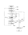
上述の撮影手順を図7のフローチャートを用いて説明する。
まず、使用者は撮影を開始する。ステップS301において、画像生成部103は、画像信号に基づいて、表示画像を生成する。
表示画像の生成には、表示画像中心移動、画像合成が含まれる。
(Shooting procedure)
The above photographing procedure will be described with reference to the flowchart of FIG.
First, the user starts shooting. In step S301, the
Display image generation includes display image center movement and image composition.
ステップS302において、画像表示部104は、表示画像を表示する。ステップS303において、制御部105は、使用者がズーム変化を行ったか否かを判断する。ステップS303の結果が偽(No)の場合、ステップS307においてレリーズが押されたか否かが判断される。
In step S302, the
ステップS307の判断結果が真(Yes)の場合、ステップS308により、画像の取り込みが行われ、フローチャートは終了する。このとき、表示範囲を画像データとして取り込むことも可能である。 If the determination result in step S307 is true (Yes), an image is captured in step S308, and the flowchart ends. At this time, it is also possible to capture the display range as image data.
ステップS307の判断結果が偽(No)の場合、ステップS303を繰り返す。
ステップS303において、ズーム変化があると判断された場合は、ステップS304へ進む。ステップS304において、ズーム倍率が所定の閾値になったか否か、すなわち拡大ズームか縮小ズームかが判断される。
If the determination result of step S307 is false (No), step S303 is repeated.
If it is determined in step S303 that there is a zoom change, the process proceeds to step S304. In step S304, it is determined whether or not the zoom magnification has reached a predetermined threshold value, that is, whether the zoom is an enlargement zoom or a reduction zoom.
ステップS304の判断結果が偽(No)の場合、ステップS301へ戻る。 If the determination result in step S304 is false (No), the process returns to step S301.
ステップS304の判断結果が真(Yes)の場合、ズームが拡大方向の場合、ズーム倍率が最大=閾値になったとき、光学系切り替え部107は、ステップS305において光学系を次に長い焦点距離の光学系に変更し、ズーム倍率を1に変更する。
これに対して、ズームが縮小方向の場合、ズーム倍率が1倍=閾値になったとき、光学系切り替え部107は、ステップS305において光学系を次に短い焦点距離の光学系に変更し、ズーム倍率を最大ズーム倍率に変更する。
なお、光学系の切り替えは、手動でも自動でも良い。
If the determination result in step S304 is true (Yes), if the zoom is in the enlargement direction, and the zoom magnification is maximum = threshold, the optical
On the other hand, when the zoom is in the reduction direction, when the zoom magnification is 1 × = threshold, the optical
The optical system may be switched manually or automatically.
ステップS306において、ズーム制御部106は、上述の判断結果に従って、ズーム倍率の変更を行い、ステップS301へ戻る。
In step S306, the
また、複数の光学系は、n個の光学系からなり、
m番目に短い焦点距離を有する光学系の焦点距離をfm(m=1〜n;m、nは整数)とする。
The plurality of optical systems includes n optical systems,
Let f m (m = 1 to n; m and n are integers) be the focal length of an optical system having the mth shortest focal length.
さらに、
焦点距離f1を広角端における焦点距離とし、
焦点距離fnを望遠端における焦点距離とそれぞれしたとき、
焦点距離fmを有する光学系は固定焦点であってもよい。
ズーム制御部106は、電子ズームによりズーミングを行うことが望ましい。
further,
Let the focal length f 1 be the focal length at the wide-angle end,
When the focal length f n is the focal length at the telephoto end,
An optical system having a focal length f m may be fixed focus.
The
電子ズームをおこなうことにより、光学ズームによるレンズの移動が不要となる。このため、撮像装置の小型化を図ることができる。さらに、機械的な駆動機構なども簡略化できる。さらに、駆動音がでないので静かにズーム可能であり、かつ電気的処理を行うので動きがスムーズであるという効果を奏する。 By performing the electronic zoom, it is not necessary to move the lens by the optical zoom. For this reason, size reduction of an imaging device can be achieved. Furthermore, a mechanical drive mechanism can be simplified. Furthermore, since there is no driving sound, zooming can be performed quietly and electric processing is performed, so that the movement is smooth.
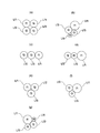
ここで、複数の光学系の配置のバリエーションに関して説明する。図8(a)、(b)、(c)、(d),(e)、(f)、(g)は、それぞれ、3つまたは4つの光学系Lf1、Lf2、Lf3、Lf4の配置を正面から見た図である。
図において、理解しやすいように、焦点距離が短くなる(広角な光学系になる)にしたがい、円形レンズの直径を大きく図示している。
Here, the variation of arrangement | positioning of a some optical system is demonstrated. 8 (a), (b), (c), (d), (e), (f), and (g) show the arrangement of three or four optical systems Lf1, Lf2, Lf3, and Lf4, respectively. It is the figure seen from the front.
In the figure, for easy understanding, the diameter of the circular lens is enlarged as the focal length is shortened (a wide-angle optical system is formed).
図9(a)は、3つの光学系Lf1、Lf2、Lf3の、それぞれの撮影範囲Af1、Af2、Af3を示している。
図9(b)は、4つの光学系Lf1、Lf2、Lf3、Lf4の、それぞれの撮影範囲Af1、Af2、Af3、Af4を示している。
FIG. 9A shows the photographing ranges Af1, Af2, and Af3 of the three optical systems Lf1, Lf2, and Lf3.
FIG. 9B shows the imaging ranges Af1, Af2, Af3, and Af4 of the four optical systems Lf1, Lf2, Lf3, and Lf4.
また、本実施形態では、以下の構成とすることが望ましい。
図10を適宜参照して説明する。
焦点距離fmを有する光学系と焦点距離fm−1を有する光学系との間でズームする時、焦点距離fmを有する光学系の光軸中心からの表示範囲の中心の水平方向の変化量、垂直方向の変化量はそれぞれ、以下の条件式(1)、(2)を満足することが好ましい。
xm、m−1=dxm,m−1×Bm,m−1/(Bm,m−1−Bm−1) (1)
ym,m−1=dym,m−1×Bm,m−1/(Bm,m−1−Bm−1) (2)
ここで、
dxm、m−1は、焦点距離fmを有する光学系の光軸中心と、焦点距離fm−1を有する光学系の光軸中心との水平方向の距離、
dym、m−1は、焦点距離fmを有する光学系の光軸中心と、焦点距離fm−1を有する光学系の光軸中心との垂直方向の距離、
Bm−1は、焦点距離fm−1を有する光学系の撮影時のズーム倍率、
Bm,m−1=fm/fm−1、
である。
また、「焦点距離fmを有する光学系と焦点距離fm−1を有する光学系との間でズームする時」とは、焦点距離fmを有する光学系をズームアウトもしくは焦点距離fm−1を有する光学系をズームインし、表示画像の中心位置を焦点距離fm−1を有する光学系もしくは焦点距離fmを有する光学系の光軸中心に向かって変化する時、を意味する。
In the present embodiment, the following configuration is desirable.
This will be described with reference to FIG.
When zooming between an optical system having an optical system and the focal length f m-1 which has a focal length f m, the horizontal change in the center of the display range from the center of the optical axis of the optical system having a focal length f m It is preferable that the amount and the amount of change in the vertical direction satisfy the following conditional expressions (1) and (2), respectively.
xm , m-1 = dxm , m-1 * Bm, m-1 / (Bm , m-1- Bm -1 ) (1)
y m, m−1 = dy m, m−1 × B m, m−1 / (B m, m−1 −B m−1 ) (2)
here,
dx m, m-1, the horizontal distance between the center of the optical axis of the optical system having a focal length f m, the center of the optical axis of the optical system having a focal length f m-1,
dy m, m-1 is the center of the optical axis of the optical system having a focal length f m, the vertical distance between the center of the optical axis of the optical system having a focal length f m-1,
B m−1 is a zoom magnification at the time of shooting of an optical system having a focal length f m−1 ,
B m, m-1 = f m / f m-1,
It is.
“When zooming between an optical system having a focal length f m and an optical system having a focal length f m−1 ” means that the optical system having the focal length f m is zoomed out or the focal length f m− is. This means when the optical system having 1 is zoomed in and the center position of the display image changes toward the optical axis center of the optical system having the focal length f m-1 or the optical system having the focal length f m .
条件式(1)、(2)は、表示範囲の中心の水平方向の変化量と、垂直方向の変化量とを規定している。なお、最大ズーム倍率は1.5〜2以下が好ましい。これにより、自然な画像変化を得られる。
さらに、表示範囲の中心位置を変化させる速度は、ズーム変化量に応じて変化することが好ましい。これにより、円滑で自然な倍率変化を得られる。
Conditional expressions (1) and (2) define the amount of change in the horizontal direction and the amount of change in the vertical direction at the center of the display range. The maximum zoom magnification is preferably 1.5 to 2 or less. Thereby, a natural image change can be obtained.
Furthermore, it is preferable that the speed at which the center position of the display range is changed changes according to the zoom change amount. Thereby, a smooth and natural magnification change can be obtained.
焦点距離fm−1を有する光学系Lfm−1をズームインし、焦点距離fmを有する光学系Lfmと同じ画角になったとき、焦点距離fmを有する光学系Lfmに切り替える場合を考える。 Zoom optical system Lf m-1 which has a focal length f m-1, when it becomes the same angle as the optical system Lf m having a focal length f m, when switching the optical system Lf m having a focal length f m think of.
焦点距離fm−1を有する光学系Lfm−1によりズーム倍率B=1のとき、最も大きな実線で示す撮影範囲で被写体を撮像できる。この状態から、ズームインしてゆき、焦点距離fm−1を有する光学系Lfm−1によりズーム倍率B=1.5のとき、表示範囲は破線で示す大きさに小さくなる。 When the zoom magnification B = 1 by the optical system Lf m−1 having the focal length f m−1 , the subject can be imaged in the photographing range indicated by the largest solid line. From this state, the zoom-in is performed, and when the zoom magnification B = 1.5 by the optical system Lf m−1 having the focal length f m−1 , the display range is reduced to the size indicated by the broken line.
さらに、焦点距離fm−1を有する光学系Lfm−1によりズームインを行い、ズーム倍率B=2になる。このとき、焦点距離fm−1を有する光学系Lfm−1をズームインし、焦点距離fmを有する光学系Lfmと同じ画角になったとき、焦点距離fmを有する光学系Lfmに切り替える。 Further, zoom-in is performed by the optical system Lf m−1 having the focal length f m−1 so that the zoom magnification B = 2. At this time, the zoom optical system Lf m-1 which has a focal length f m-1, the focal length when it is the same angle as the optical system Lf m with f m, optics Lf m having a focal length f m Switch to.
焦点距離fmを有する光学系Lfmは、点線で示す撮影範囲を有している。焦点距離fm−1のズーム時表示画像の中心が矢印の方向に変化する。 Optics Lf m having a focal length f m has an imaging range indicated by the dotted line. The center of the display image at the time of zooming with the focal length fm -1 changes in the direction of the arrow.
画角の変化を、擬似的に焦点距離として換算した観点からさらに説明を続ける。
光学系Lfm−1のズーム最大倍率Bm−1max=2.5とする。上述したように、光学系Lfm−1のズーム倍率Bm−1=2において、焦点距離fm−1と焦点距離fmは一致する。そして、以下の表1に示すように2<Bm−1では、両光学系の画角に重なりが生じる。
The description will be further continued from the viewpoint of converting the change in the angle of view into a pseudo focal length.
The zoom maximum magnification B m−1 max of the optical system Lf m−1 is set to 2.5. As described above, at the zoom magnification B m−1 = 2 of the optical system Lf m−1 , the focal length f m−1 and the focal length f m coincide. As shown in Table 1 below, when 2 <B m−1 , the field angles of both optical systems overlap.
(表1)
fm−1のズーム倍率Bm−1 1倍の時 2倍の時 2.5倍の時
fm−1=25mm 25mm 50mm 62.5mm
fm =50mm 50mm
(Table 1)
f m-1 zoom magnification B m-1 1x 2x 2.5x fm -1 = 25mm 25mm 50mm 62.5mm
f m = 50
ズーム倍率を変化させた場合でも、光学系Lfmと、Lfm−1との光軸同士の間隔は変わらない。このため、上述したように、ズーム倍率最大ではなく、fm/fm−1を用いて、表示範囲の中心の水平方向の変化量と、垂直方向の変化量とを規定することが望ましい。 Even when changing the zoom magnification, an optical system Lf m, distance between the optical axes of the Lf m-1 does not change. For this reason, as described above, it is desirable to define the amount of change in the horizontal direction and the amount of change in the vertical direction at the center of the display range using fm / fm -1 instead of the maximum zoom magnification.
条件式(1)、(2)を満足することで、ズーム変化量に応じて表示範囲の中心位置を変化させることができる。これにより、光学系の切り替え後の撮影範囲が一気にシフトしてしまうことを防止できる。 When the conditional expressions (1) and (2) are satisfied, the center position of the display range can be changed according to the zoom change amount. Thereby, it is possible to prevent the photographing range after the switching of the optical system from being shifted at a stretch.
また、本実施形態では、幾何光学的に以下の条件式を満足することが好ましい。
dxm,m−1<Lm×(Tanθxm−1−A×Tanθxm) (3)
dym,m−1<Lm×(Tanθym−1−A×Tanθym) (4)
Bm,m−1=fm/fm−1
10≧A≧1
ここで、
dxm、m−1は、焦点距離fmを有する光学系の光軸中心と、焦点距離fm−1を有する光学系の光軸中心との水平方向の距離、
dym、m−1は、焦点距離fmを有する光学系の光軸中心と、焦点距離fm−1を有する光学系の光軸中心との垂直方向の距離、
Bm−1は、焦点距離fm−1を有する光学系の撮影時のズーム倍率、
θxm、θxm−1は、x方向の半画角、
θym、θym−1は、y方向の半画角、
Aは係数、である。
なお、係数はA≧2が好ましい。
In the present embodiment, it is preferable that the following conditional expression is satisfied geometrically.
dx m, m−1 <L m × (Tan θx m−1 −A × Tan θx m ) (3)
dy m, m−1 <L m × (Tanθy m−1 −A × Tanθy m ) (4)
B m, m-1 = f m / f m-1
10 ≧ A ≧ 1
here,
dx m, m-1, the horizontal distance between the center of the optical axis of the optical system having a focal length f m, the center of the optical axis of the optical system having a focal length f m-1,
dy m, m-1 is the center of the optical axis of the optical system having a focal length f m, the vertical distance between the center of the optical axis of the optical system having a focal length f m-1,
B m−1 is a zoom magnification at the time of shooting of an optical system having a focal length f m−1 ,
θx m and θx m−1 are half angles of view in the x direction,
θym , θym -1 are half field angles in the y direction,
A is a coefficient.
The coefficient is preferably A ≧ 2.
条件式(3)、(4)は、光学系の光軸同士の距離と、撮影可能な至近距離と撮像素子との大きさと焦点距離との関係を規定している。撮影範囲のシフト量を規制(抑制)する条件を示している。 Conditional expressions (3) and (4) define the relationship between the distance between the optical axes of the optical system, the closest distance that can be photographed, the size of the image sensor, and the focal length. The conditions for restricting (suppressing) the shift amount of the photographing range are shown.
焦点距離fm−1を有する光学系Lfm−1の撮影範囲に、焦点距離fmを有する光学系Lfmの撮影範囲をどの程度含めるか、を規定する。例えば、1≦Aの場合、光学系Lfm−1の撮影範囲に、光学系Lfmの撮影範囲の中心まで含ませることができる。また、2≦Aの場合、光学系Lfm−1の撮影範囲に、光学系Lfmの撮影範囲を全て含ませることができる。 It defines how much the imaging range of the optical system Lf m having the focal length f m is included in the imaging range of the optical system Lf m−1 having the focal length f m−1 . For example, in the case of 1 ≦ A, the imaging range of the optical system Lf m −1 can be included up to the center of the imaging range of the optical system Lfm. Also, in the case of 2 ≦ A, the imaging range of the optical system Lf m-1, it is possible to include all the imaging range of the optical system Lf m.
また、本実施形態では、2>A>1おいて、
ズーム倍率m>1の場合の焦点距離fmを有する光学系の撮影範囲は、少なくとも他の光学系の撮影範囲に含まれており、
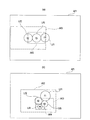
画像生成部103は、表示範囲の中心が変化した際の表示範囲において、選択されている光学系による撮影範囲外の画像を、選択されていない他の光学系による撮影範囲内の画像を用いて補完することが好ましい。
In the present embodiment, 2>A> 1
The imaging range of the optical system having the focal length f m when the zoom magnification m> 1 is included in at least the imaging range of the other optical system,
The
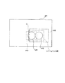
図12に示すように、焦点距離f2を有する光学系Lf2でズームを行いながら、焦点距離f3を有する光学系Lf3による撮影範囲(点線で示す)の中心方向へ画像の中心を変化するとき、シフト途中の表示範囲(一点鎖線で示す)に対して、光学系Lf3による撮影範囲(点線で示す)の斜線Yで示す部分は撮影範囲外になる。
このとき、光学系Lf1による撮影範囲Af1内の斜線Yと同じ範囲の画像情報Yを使用して斜線Yの画像を生成する。周辺部における補完であるため、画像全体に対して、画質の劣化の影響を抑えつつ補完可能である。
As shown in FIG. 12, while the zoom optical system Lf2 having a focal length f 2, when changing the center of the image toward the center of the imaging range of the optical system Lf3 having a focal length f 3 (shown in phantom) For the display range in the middle of the shift (indicated by the alternate long and short dash line), the portion indicated by the oblique line Y in the imaging range (indicated by the dotted line) by the optical system Lf3 is outside the imaging range.
At this time, an image of the oblique line Y is generated using the image information Y in the same range as the oblique line Y in the imaging range Af1 by the optical system Lf1. Since it is complementation in the peripheral part, it is possible to complement the entire image while suppressing the influence of image quality degradation.
また、画像生成部103は、焦点距離fmを有する光学系Lfmの撮影画像と、焦点距離fm−1を有する光学系Lfm−1の撮影画像とを用いて表示画像を生成することがこのましい。
これにより、解像度を向上し、より自然な画像を生成することができる。
The
Thereby, the resolution can be improved and a more natural image can be generated.
また、画像表示部104は、表示画像中心の移動方向を表示することが好ましい。
図11に示すように、ズーム動作に応じて、表示範囲は変化する。この際、表示範囲の中心の移動方向を表示することで、使用者が被写体を見失うことを防止できる。これにより、さらに撮影が容易になる。
The
As shown in FIG. 11, the display range changes according to the zoom operation. At this time, displaying the moving direction of the center of the display range can prevent the user from losing sight of the subject. This further facilitates shooting.
また、制御部105は、複数の光学系の切り替え時に、撮像画像のボケの変化が少ないFナンバーを有する光学系へ切り替えを行い、
以下の条件式(5)、(6)を満足することが好ましい。
FNOm−1=FNOm/((fm/fm−1)2) (5)
fm>fm−1 (6)
ここで、
FNOm−1は、焦点距離fm−1を有する光学系Lfm−1のFナンバー、
FNOmは、焦点距離fmを有する光学系LfmのFナンバー、
である。
Further, the
It is preferable that the following conditional expressions (5) and (6) are satisfied.
FNO m-1 = FNO m / ((f m / f m-1) 2) (5)
f m > f m−1 (6)
here,
FNO m−1 is the F number of the optical system Lf m−1 having the focal length f m−1 ,
FNO m is the F number of the optical system Lf m having the focal length f m ,
It is.
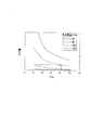
光学系を切り替えることで、図13に示すように焦点距離に応じて被写界深度が変化する。条件式(5)、(6)を満足することで、光学系の切り替え時のボケ量の変化を低減できる。なお、ボケ量は、点光源を撮影したときの、撮像素子上での点光源の像の拡がりに基づいて判断する。 By switching the optical system, the depth of field changes according to the focal length as shown in FIG. By satisfying conditional expressions (5) and (6), it is possible to reduce a change in the amount of blur at the time of switching the optical system. Note that the amount of blur is determined based on the spread of the image of the point light source on the image sensor when the point light source is photographed.
また、制御部105は、焦点距離に応じて各光学系に対する撮像面のサイズを変える(広角は大きくし、望遠は小さくする)ことが好ましい。
これにより、効率的な撮影が可能となる。また、図14(a)、(b)に示すように、
光学系同士の光軸を近づけることで小型化も可能となる。
例えば、制御部105は、各光学系の焦点距離が広角側のときに比較して望遠側のときは、撮像面のサイズを小さくすることが好ましい。なお、撮像素子は光学系1つに対して1つ、もしくは全光学系に対して1つでもよい。
Further, it is preferable that the
Thereby, efficient photographing can be performed. As shown in FIGS. 14A and 14B,
Miniaturization is also possible by bringing the optical axes of the optical systems closer to each other.
For example, the
また、本実施形態において、少なくとも1つの光学系は、1枚以上の屈折力可変レンズを有する(フォーカス調整用)ことが好ましい。
屈折力可変レンズを用いることで、光学ズームによるレンズ駆動がないため、効果的に薄型化かつフォーカシングが可能となる。
In the present embodiment, it is preferable that at least one optical system has one or more refractive power variable lenses (for focus adjustment).
By using the variable refractive power lens, there is no lens drive by optical zoom, and therefore it is possible to effectively reduce the thickness and focus.
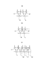
また、複数の光学系のうち、少なくとも最も焦点距離の長い光学系において、被写体からの光が光学系を構成するレンズ内で1回以上反射し、かつ、少なくとも最も焦点距離の長い光学系の被写体側のレンズ面から撮像素子までの距離と、その他の光学系の被写体側のレンズ面から撮像素子までの距離と略同じように構成することが好ましい。 Also, among the plurality of optical systems, at least in the optical system having the longest focal length, the light from the subject is reflected one or more times within the lens constituting the optical system, and at least the subject of the optical system having the longest focal length It is preferable that the distance from the lens surface on the side to the image sensor is substantially the same as the distance from the lens surface on the subject side of the other optical system to the image sensor.
図14(c)の4つのレンズL1、L2、L3、L4のうちの、レンズL4は、被写体からの光が光学系を構成するレンズ内で1回以上反射し、かつ撮像素子Iまでの距離は他のレンズL1、L2、L3と同じである。
これにより、図14(c)に示すように、さらなる撮像装置の小型化を達成できる。
Of the four lenses L1, L2, L3, and L4 in FIG. 14C, the lens L4 reflects light from the subject one or more times within the lens constituting the optical system, and the distance to the image sensor I. Is the same as the other lenses L1, L2, and L3.
Thereby, as shown in FIG.14 (c), further size reduction of an imaging device can be achieved.
また、画像生成部103は、焦点距離fmを有する光学系Lfmの画像と、焦点距離fm−1を有する光学系Lfm−1の画像とから視差量を変化させた画像を生成することが望ましい。そして画像表示部104は、生成した画像を表示する。
The
これにより、視点位置もシフトした画像を生成することができる。
焦点距離fmを有する光学系Lfmの画像と、焦点距離fm−1を有する光学系Lfm−1の画像との2枚の視差画像から、中間の視差を持った画像を生成することができる。例えば、焦点距離fmを有する光学系Lfmの画像と、焦点距離fm−1を有する光学系Lfm−1の画像との視差が1の場合、視差量0.5の画像を生成できる。換言すると、右目で光学系Lfmの画像を観察し、左目で焦点距離fm−1を観察するとき、両眼では、画像を半分ずつ0.5の割合で観察する。
Thereby, an image in which the viewpoint position is also shifted can be generated.
An image optical system Lf m having a focal length f m, of two parallax images with an optical system Lf m-1 of the image having a focal length f m-1, to produce an image having an intermediate parallax Can do. For example, if the image of the optical system Lf m having a focal length f m, the parallax between the optical system Lf m-1 of the image having a focal length f m-1 of 1, can generate an image of the parallax amount 0.5 . In other words, by observing the image of the optical system Lf m in the right eye, when observing the focal length f m-1 in the left eye, the binocular, observed at a rate of two halves image 0.5.
この結果、光学系を切り替えた時の視差のずれを低減できる。 As a result, the shift in parallax when the optical system is switched can be reduced.
また、画像生成部103は、焦点距離fmを有する光学系Lfmと、焦点距離fm−1を有する光学系Lfm−1とでズームする時、焦点距離fmを有する光学系Lfmの光軸(光学中心)からの表示画像の中心の水平方向変化量xm,m−1、垂直方向変化量ym,m−1の少なくともどちらかの量に応じた視差量の画像を生成することが好ましい。
The
この結果、生成する画像の視差量は、表示画像の中心の変化量で変わる。このため、少なくとも水平方向変化量、垂直方向変化量のどちらかの量に応じた視差量の画像を生成することにより、光学系を切り替えた時の視差のずれを低減できる。 As a result, the amount of parallax of the generated image varies with the amount of change in the center of the display image. For this reason, by generating an image having a parallax amount corresponding to at least one of the horizontal direction change amount and the vertical direction change amount, a shift in parallax when the optical system is switched can be reduced.
以上説明したように、本実施形態では、ズーム倍率の変化に合わせて表示画像の中心を変化させることで、光学系切り替えによる撮影範囲のシフト量を抑制し、不自然な印象を緩和することができる。また、撮影範囲の大きなシフトによって、使用者が被写体を見失しなうことを防ぐことができる。
さらに、ボケや被写界深度の急激な変化を防ぐことで、光学系切り替えによる不自然な印象を緩和できる。
As described above, in the present embodiment, by changing the center of the display image in accordance with the change of the zoom magnification, the shift amount of the shooting range due to the switching of the optical system can be suppressed and the unnatural impression can be alleviated. it can. In addition, it is possible to prevent the user from losing sight of the subject due to a large shift in the shooting range.
Furthermore, by preventing sudden changes in blur and depth of field, unnatural impressions due to switching of optical systems can be alleviated.
以上のように、本発明にかかる撮像装置は、複数の光学系を有し、ズームを行う撮像装置に有用である。 As described above, the imaging apparatus according to the present invention is useful for an imaging apparatus that has a plurality of optical systems and performs zooming.
100 撮像装置
101 レンズ
102 撮像素子
103 画像生成部
104 画像表示部
105 制御部
106 ズーム制御部
107 光学系切り替え部
200 携帯電話
201 表示部
202a、202b、202c、202d 光学系
Lf1、Lf2、Lf3、Lf4 光学系
Af1、Af2、Af3、Af4 撮影範囲
AX 光軸
ENP 入射瞳
OBJ 被写体
DESCRIPTION OF
Claims (11)
前記光学系により被写体を撮像する撮像素子と、
前記複数の光学系の少なくとも一つの光学系による出力画像の画角を変化させるズーム制御部と、を有し、
変化する画角の一部が、他の光学系の画角と同じであり、
さらに、
ズーム時の表示画像の中心位置を、前記画角の一部が同じである前記他の光学系の光軸中心に向かって変化させる制御部を有することを特徴とする撮像装置。 A plurality of optical systems having different focal lengths;
An image sensor for imaging a subject by the optical system;
A zoom control unit that changes an angle of view of an output image by at least one optical system of the plurality of optical systems,
Part of the changing angle of view is the same as the angle of view of other optical systems,
further,
An image pickup apparatus comprising: a control unit configured to change a center position of a display image during zooming toward an optical axis center of the other optical system having a part of the angle of view.
m番目に短い焦点距離を有する光学系の焦点距離をfm(m=1〜n;m、nは整数)とし、
焦点距離f1を広角端における焦点距離とし、
焦点距離fnを望遠端における焦点距離とそれぞれしたとき、
焦点距離fmを有する光学系は固定焦点であり、
前記ズーム制御部は、電子ズームによりズーミングを行うことを特徴とする請求項1に記載の撮像装置。 The plurality of optical systems includes n optical systems,
Let f m (m = 1 to n; m and n are integers) be the focal length of an optical system having the mth shortest focal length,
Let the focal length f 1 be the focal length at the wide-angle end,
When the focal length f n is the focal length at the telephoto end,
An optical system having a focal length f m is a fixed focus,
The imaging apparatus according to claim 1, wherein the zoom control unit performs zooming by electronic zoom.
xm、m−1=dxm,m−1×Bm,m−1/(Bm,m−1−Bm−1) (1)
ym,m−1=dym,m−1×Bm,m−1/(Bm,m−1−Bm−1) (2)
ここで、
dxm、m−1は、前記焦点距離fmを有する光学系の光軸中心と、前記焦点距離fm−1を有する光学系の光軸中心との水平方向の距離、
dym、m−1は、前記焦点距離fmを有する光学系の光軸中心と、前記焦点距離fm−1を有する光学系の光軸中心との垂直方向の距離、
Bm−1は、焦点距離fm−1を有する光学系の撮影時のズーム倍率、
Bm,m−1=fm/fm−1、
である。 When zooming between the optical system having the optical system focal length f m-1 with the focal length f m, the horizontal center of the display image from the center of the optical axis of the optical system having the focal length f m The imaging apparatus according to claim 1 or 2, wherein the direction change amount and the vertical direction change amount satisfy the following conditional expressions (1) and (2), respectively.
xm , m-1 = dxm , m-1 * Bm, m-1 / (Bm , m-1- Bm -1 ) (1)
y m, m−1 = dy m, m−1 × B m, m−1 / (B m, m−1 −B m−1 ) (2)
here,
dx m, m−1 is the horizontal distance between the optical axis center of the optical system having the focal length f m and the optical axis center of the optical system having the focal length f m−1 ,
dy m, m-1 is the center of the optical axis of the optical system having the focal length f m, the vertical distance between the center of the optical axis of the optical system having the focal length f m-1,
B m−1 is a zoom magnification at the time of shooting of an optical system having a focal length f m−1 ,
B m, m-1 = f m / f m-1,
It is.
dxm,m−1<Lm×(Tanθxm−1−A×Tanθxm) (3)
dym,m−1<Lm×(Tanθym−1−A×Tanθym) (4)
Bm,m−1=fm/fm−1
10≧A≧1
ここで、
dxm、m−1は、前記焦点距離fmを有する光学系の光軸中心と、前記焦点距離fm−1を有する光学系の光軸中心との水平方向の距離、
dym、m−1は、前記焦点距離fmを有する光学系の光軸中心と、前記焦点距離fm−1を有する光学系の光軸中心との垂直方向の距離、
Bm−1は、焦点距離fm−1を有する光学系の撮影時のズーム倍率、
θxm、θxm−1は、x方向の半画角、
θym、θym−1は、y方向の半画角、
Aは係数、である。 The imaging apparatus according to claim 1, wherein the following conditional expressions (3) and (4) are satisfied.
dx m, m−1 <L m × (Tan θx m−1 −A × Tan θx m ) (3)
dy m, m−1 <L m × (Tanθy m−1 −A × Tanθy m ) (4)
B m, m-1 = f m / f m-1
10 ≧ A ≧ 1
here,
dx m, m−1 is the horizontal distance between the optical axis center of the optical system having the focal length f m and the optical axis center of the optical system having the focal length f m−1 ,
dy m, m-1 is the center of the optical axis of the optical system having the focal length f m, the vertical distance between the center of the optical axis of the optical system having the focal length f m-1,
B m−1 is a zoom magnification at the time of shooting of an optical system having a focal length f m−1 ,
θx m and θx m−1 are half angles of view in the x direction,
θym , θym -1 are half field angles in the y direction,
A is a coefficient.
m>1の場合の焦点距離fmを有する光学系の撮影範囲は、少なくとも他の光学系の撮影範囲に含まれ、
前記画像生成部は、表示範囲の中心が変化した際の表示範囲において、選択されている光学系による撮影範囲外の画像を、選択されていない他の光学系による撮影範囲内の画像を用いて補完することを特徴とする請求項4に記載の撮像装置。 2>A> 1,
The imaging range of the optical system having the focal length f m when m> 1 is included in at least the imaging range of the other optical system,
In the display range when the center of the display range is changed, the image generation unit uses an image outside the shooting range by the selected optical system using an image in the shooting range by another non-selected optical system. The image pickup apparatus according to claim 4, wherein the image pickup apparatus complements the image pickup apparatus.
以下の条件式を満足することを特徴とする請求項1〜7のいずれか一項に記載の撮像装置。
FNOm−1=FNOm/((fm/fm−1)2) (5)
fm>fm−1 (6)
ここで、
FNOm−1は、前記焦点距離fm−1を有する光学系のFナンバー、
FNOmは、前記焦点距離fmを有する光学系のFナンバー、
である。 The control unit switches to an optical system having an F number with little change in blur of a captured image when switching the plurality of optical systems.
The image pickup apparatus according to claim 1, wherein the following conditional expression is satisfied.
FNO m-1 = FNO m / ((f m / f m-1) 2) (5)
f m > f m−1 (6)
here,
FNO m−1 is the F number of the optical system having the focal length f m−1 ,
FNO m is the F number of the optical system having the focal length f m ,
It is.
かつ、少なくとも最も焦点距離の長い前記光学系の被写体側のレンズ面から撮像素子までの距離と、その他の前記光学系の被写体側のレンズ面から撮像素子までの距離と同じことを特徴とする請求項1〜10のいずれか一項に記載の撮像装置。 Among the plurality of optical systems, at least in the optical system having the longest focal length, the light from the subject is reflected one or more times in the lens constituting the optical system,
The distance from the lens surface on the subject side of the optical system having the longest focal length to the imaging device is the same as the distance from the lens surface on the subject side of the other optical system to the imaging device. Item 11. The imaging device according to any one of Items 1 to 10.
Priority Applications (2)
| Application Number | Priority Date | Filing Date | Title |
|---|---|---|---|
| JP2012004358A JP2013143753A (en) | 2012-01-12 | 2012-01-12 | Imaging apparatus |
| US13/737,699 US9030578B2 (en) | 2012-01-12 | 2013-01-09 | Image pickup apparatus |
Applications Claiming Priority (1)
| Application Number | Priority Date | Filing Date | Title |
|---|---|---|---|
| JP2012004358A JP2013143753A (en) | 2012-01-12 | 2012-01-12 | Imaging apparatus |
Publications (1)
| Publication Number | Publication Date |
|---|---|
| JP2013143753A true JP2013143753A (en) | 2013-07-22 |
Family
ID=48779713
Family Applications (1)
| Application Number | Title | Priority Date | Filing Date |
|---|---|---|---|
| JP2012004358A Pending JP2013143753A (en) | 2012-01-12 | 2012-01-12 | Imaging apparatus |
Country Status (2)
| Country | Link |
|---|---|
| US (1) | US9030578B2 (en) |
| JP (1) | JP2013143753A (en) |
Cited By (3)
| Publication number | Priority date | Publication date | Assignee | Title |
|---|---|---|---|---|
| JP2016540417A (en) * | 2013-10-18 | 2016-12-22 | ザ ライト・コ インコーポレイテッド | Image capture control method and apparatus |
| US10274706B2 (en) | 2013-10-18 | 2019-04-30 | Light Labs Inc. | Image capture control methods and apparatus |
| JP2021520151A (en) * | 2019-01-30 | 2021-08-12 | アークソフト コーポレイション リミテッドArcSoft Corporation Limited | Zoom method and electronic devices to which it is applied |
Families Citing this family (54)
| Publication number | Priority date | Publication date | Assignee | Title |
|---|---|---|---|---|
| CN116405747A (en) | 2012-11-28 | 2023-07-07 | 核心光电有限公司 | Multi-aperture imaging system and method for acquiring images through multi-aperture imaging system |
| CN109194849B (en) | 2013-06-13 | 2021-01-15 | 核心光电有限公司 | Dual Aperture Zoom Digital Camera |
| CN108549119A (en) | 2013-07-04 | 2018-09-18 | 核心光电有限公司 | Small-sized focal length lens external member |
| CN108718376B (en) | 2013-08-01 | 2020-08-14 | 核心光电有限公司 | Thin multi-aperture imaging system with auto-focus and method of use thereof |
| US9392188B2 (en) | 2014-08-10 | 2016-07-12 | Corephotonics Ltd. | Zoom dual-aperture camera with folded lens |
| WO2016108093A1 (en) | 2015-01-03 | 2016-07-07 | Corephotonics Ltd. | Miniature telephoto lens module and a camera utilizing such a lens module |
| CN107407849B (en) | 2015-04-02 | 2018-11-06 | 核心光电有限公司 | Dual Voice Coil Coil Motor Structure in Dual Optical Module Camera |
| US9927600B2 (en) | 2015-04-16 | 2018-03-27 | Corephotonics Ltd | Method and system for providing auto focus and optical image stabilization in a compact folded camera |
| KR102114595B1 (en) | 2015-05-28 | 2020-05-25 | 코어포토닉스 리미티드 | Bi-directional stiffness for optical image stabilization and auto-focus in a dual-aperture digital camera |
| CN107852467B (en) | 2015-08-13 | 2021-01-26 | 核心光电有限公司 | Dual aperture zoom camera with video support and switching/non-switching dynamic control |
| EP3335077B1 (en) | 2015-09-06 | 2019-08-14 | Corephotonics Ltd. | Auto focus and optical image stabilization with roll compensation in a compact folded camera |
| EP3398324B1 (en) | 2015-12-29 | 2022-05-11 | Corephotonics Ltd. | Dual-aperture zoom digital camera with automatic adjustable tele field of view |
| KR102002718B1 (en) | 2016-05-30 | 2019-10-18 | 코어포토닉스 리미티드 | Rotary Ball-Guid Voice Coil Motor |
| CN112217977A (en) | 2016-06-19 | 2021-01-12 | 核心光电有限公司 | Frame synchronization in dual-aperture camera systems |
| KR102903119B1 (en) | 2016-07-07 | 2025-12-22 | 코어포토닉스 리미티드 | Linear ball guided voice coil motor for folded optic |
| WO2018007951A1 (en) | 2016-07-07 | 2018-01-11 | Corephotonics Ltd. | Dual-camera system with improved video smooth transition by image blending |
| KR102609464B1 (en) * | 2016-10-18 | 2023-12-05 | 삼성전자주식회사 | The Electronic Device Shooting Image |
| CN114051092B (en) | 2016-12-28 | 2024-07-26 | 核心光电有限公司 | Actuator with extended light folding element scanning range and folding camera comprising same |
| EP4145206A1 (en) | 2017-01-12 | 2023-03-08 | Corephotonics Ltd. | Compact folded camera |
| CN113341529B (en) | 2017-02-23 | 2023-09-19 | 核心光电有限公司 | Folding camera lens design |
| JP2020512581A (en) | 2017-03-15 | 2020-04-23 | コアフォトニクス リミテッド | Camera with panoramic scanning range |
| KR102348504B1 (en) | 2017-08-23 | 2022-01-10 | 삼성전자주식회사 | Method for reducing parallax of a plurality of cameras and electronic device supporting the same |
| US10904512B2 (en) | 2017-09-06 | 2021-01-26 | Corephotonics Ltd. | Combined stereoscopic and phase detection depth mapping in a dual aperture camera |
| US10951834B2 (en) | 2017-10-03 | 2021-03-16 | Corephotonics Ltd. | Synthetically enlarged camera aperture |
| KR102104761B1 (en) | 2017-11-23 | 2020-04-27 | 코어포토닉스 리미티드 | Compact folded camera structure |
| US10976567B2 (en) | 2018-02-05 | 2021-04-13 | Corephotonics Ltd. | Reduced height penalty for folded camera |
| CN113568251B (en) | 2018-02-12 | 2022-08-30 | 核心光电有限公司 | Digital camera and method for providing focus and compensating for camera tilt |
| US10694168B2 (en) | 2018-04-22 | 2020-06-23 | Corephotonics Ltd. | System and method for mitigating or preventing eye damage from structured light IR/NIR projector systems |
| EP3822588B1 (en) | 2018-04-23 | 2022-09-07 | Corephotonics Ltd. | An optical-path folding-element with an extended two degree of freedom rotation range |
| KR20210003856A (en) | 2018-07-04 | 2021-01-12 | 코어포토닉스 리미티드 | Camera with scanning optical path folding elements for automotive or surveillance applications |
| CN111316346B (en) | 2018-08-04 | 2022-11-29 | 核心光电有限公司 | Switchable continuous display information system above camera |
| WO2020039302A1 (en) | 2018-08-22 | 2020-02-27 | Corephotonics Ltd. | Two-state zoom folded camera |
| US11287081B2 (en) | 2019-01-07 | 2022-03-29 | Corephotonics Ltd. | Rotation mechanism with sliding joint |
| KR102494006B1 (en) | 2019-03-09 | 2023-01-30 | 코어포토닉스 리미티드 | System and method for dynamic stereoscopic calibration |
| CN109905604B (en) * | 2019-03-29 | 2021-09-21 | 深圳市道通智能航空技术股份有限公司 | Focusing method and device, shooting equipment and aircraft |
| KR102515482B1 (en) | 2019-07-31 | 2023-03-29 | 코어포토닉스 리미티드 | System and method for creating background blur in camera panning or motion |
| US11659135B2 (en) | 2019-10-30 | 2023-05-23 | Corephotonics Ltd. | Slow or fast motion video using depth information |
| CN119179196A (en) | 2019-12-03 | 2024-12-24 | 核心光电有限公司 | Actuator with a spring |
| US11949976B2 (en) | 2019-12-09 | 2024-04-02 | Corephotonics Ltd. | Systems and methods for obtaining a smart panoramic image |
| KR102708591B1 (en) | 2019-12-09 | 2024-09-20 | 코어포토닉스 리미티드 | System and method for obtaining smart panoramic images |
| CN114641805A (en) | 2020-02-22 | 2022-06-17 | 核心光电有限公司 | Split screen feature for macro photography |
| WO2021220080A1 (en) | 2020-04-26 | 2021-11-04 | Corephotonics Ltd. | Temperature control for hall bar sensor correction |
| KR20240096759A (en) | 2020-05-17 | 2024-06-26 | 코어포토닉스 리미티드 | Image stitching in the presence of a full field of view reference image |
| EP4191332B1 (en) | 2020-05-30 | 2024-07-03 | Corephotonics Ltd. | Systems and methods for obtaining a super macro image |
| EP4202521B1 (en) | 2020-07-15 | 2025-03-19 | Corephotonics Ltd. | Point of view aberrations correction in a scanning folded camera |
| US11637977B2 (en) | 2020-07-15 | 2023-04-25 | Corephotonics Ltd. | Image sensors and sensing methods to obtain time-of-flight and phase detection information |
| EP4065934A4 (en) | 2020-07-31 | 2023-07-26 | Corephotonics Ltd. | HALL SENSOR MAGNET GEOMETRY FOR LINEAR POSITION DETECTION WITH LARGE STROKE |
| KR102480820B1 (en) | 2020-08-12 | 2022-12-22 | 코어포토닉스 리미티드 | Optical Image Stabilization of Scanning Folded Cameras |
| KR102859996B1 (en) * | 2020-11-25 | 2025-09-15 | 삼성전자주식회사 | Electronic devices including multiple cameras and methods of controlling the electronic devices |
| KR102732457B1 (en) | 2020-12-26 | 2024-11-19 | 코어포토닉스 리미티드 | Video support in a multi-aperture mobile camera with a scanning zoom camera |
| TWI836372B (en) | 2021-03-11 | 2024-03-21 | 以色列商核心光電有限公司 | Systems for pop-out camera |
| KR20240025049A (en) | 2021-06-08 | 2024-02-26 | 코어포토닉스 리미티드 | Systems and cameras for tilting a focal plane of a super-macro image |
| KR102666903B1 (en) | 2021-07-21 | 2024-05-16 | 코어포토닉스 리미티드 | Pop-out mobile cameras and actuators |
| CN121091576A (en) | 2022-03-24 | 2025-12-09 | 核心光电有限公司 | Thin compact lens optical image stabilization |
Family Cites Families (9)
| Publication number | Priority date | Publication date | Assignee | Title |
|---|---|---|---|---|
| JPH04348261A (en) | 1991-05-27 | 1992-12-03 | Kajima Corp | Method for observing crazing by electronic camera |
| US6128416A (en) * | 1993-09-10 | 2000-10-03 | Olympus Optical Co., Ltd. | Image composing technique for optimally composing a single image from a plurality of digital images |
| JP2006221603A (en) * | 2004-08-09 | 2006-08-24 | Toshiba Corp | 3D information restoration device, 3D information restoration method, and 3D information restoration program |
| JP4348261B2 (en) | 2004-08-31 | 2009-10-21 | Hoya株式会社 | Trimming imaging device |
| JP4573724B2 (en) | 2005-08-01 | 2010-11-04 | イーストマン コダック カンパニー | Imaging apparatus having a plurality of optical systems |
| JP4624245B2 (en) | 2005-11-29 | 2011-02-02 | イーストマン コダック カンパニー | Imaging device |
| US8824833B2 (en) * | 2008-02-01 | 2014-09-02 | Omnivision Technologies, Inc. | Image data fusion systems and methods |
| FI20085510A7 (en) * | 2008-05-28 | 2009-11-29 | Valtion Teknillinen Tutkimuskeskus | Zoom camera arrangement comprising multiple sub-cameras |
| JP5258722B2 (en) * | 2009-09-24 | 2013-08-07 | 富士フイルム株式会社 | Compound eye camera and control method thereof |
-
2012
- 2012-01-12 JP JP2012004358A patent/JP2013143753A/en active Pending
-
2013
- 2013-01-09 US US13/737,699 patent/US9030578B2/en not_active Expired - Fee Related
Cited By (5)
| Publication number | Priority date | Publication date | Assignee | Title |
|---|---|---|---|---|
| JP2016540417A (en) * | 2013-10-18 | 2016-12-22 | ザ ライト・コ インコーポレイテッド | Image capture control method and apparatus |
| US10274706B2 (en) | 2013-10-18 | 2019-04-30 | Light Labs Inc. | Image capture control methods and apparatus |
| JP2021520151A (en) * | 2019-01-30 | 2021-08-12 | アークソフト コーポレイション リミテッドArcSoft Corporation Limited | Zoom method and electronic devices to which it is applied |
| JP7142104B2 (en) | 2019-01-30 | 2022-09-26 | アークソフト コーポレイション リミテッド | ZOOM METHOD AND ELECTRONIC DEVICE USING THE SAME |
| US11490016B2 (en) | 2019-01-30 | 2022-11-01 | Arcsoft Corporation Limited | Zooming method and electronic device using the same |
Also Published As
| Publication number | Publication date |
|---|---|
| US9030578B2 (en) | 2015-05-12 |
| US20130182150A1 (en) | 2013-07-18 |
Similar Documents
| Publication | Publication Date | Title |
|---|---|---|
| JP2013143753A (en) | Imaging apparatus | |
| JP5601598B2 (en) | Inner focus type large-aperture medium telephoto lens, imaging optical device and digital equipment | |
| JP5623356B2 (en) | Imaging device | |
| US8988538B2 (en) | Image pickup apparatus and lens apparatus | |
| JP4894041B2 (en) | Electronic imaging device | |
| JP6207963B2 (en) | Bending imaging optical system | |
| JP5755188B2 (en) | Imaging device and lens device | |
| US9253382B2 (en) | Zoom lens and image pickup apparatus | |
| EP2995982B1 (en) | Lens barrel, camera system, and imaging device | |
| CN108227159B (en) | Optical system, optical apparatus, and image pickup apparatus | |
| JP2011055246A (en) | Telescopic imaging apparatus | |
| JP5745183B2 (en) | Imaging apparatus and imaging method | |
| US10353186B2 (en) | Zoom lens and image pickup apparatus including the same | |
| JP2012113281A (en) | Stereoscopic imaging optical system, imaging device and camera | |
| JP2009206831A (en) | Imaging apparatus, method of generating image, and electronic equipment | |
| US9407801B2 (en) | Compound eye image pickup apparatus | |
| JP2017187693A (en) | Image blur correction device and control method thereof, program, and storage medium | |
| JP6064403B2 (en) | Camera, camera system, electronic device, program | |
| WO2012035971A1 (en) | Imaging device, imaging method, and recording medium | |
| US10051190B2 (en) | Interchangeable lens, camera system, imaging apparatus, control method of camera system, and control method of imaging apparatus in which the size of an image circle varies inversely to the focal distance | |
| JP2014219473A (en) | Interchangeable lens | |
| JP2016134817A (en) | Compound-eye imaging apparatus and compound-eye imaging control program | |
| JP5872874B2 (en) | Imaging device and method for controlling imaging device | |
| JP2019109271A (en) | Imaging device | |
| KR20070097638A (en) | Device and method for adjusting the depth of field of the camera |