JP4624245B2 - Imaging device - Google Patents
Imaging device Download PDFInfo
- Publication number
- JP4624245B2 JP4624245B2 JP2005344624A JP2005344624A JP4624245B2 JP 4624245 B2 JP4624245 B2 JP 4624245B2 JP 2005344624 A JP2005344624 A JP 2005344624A JP 2005344624 A JP2005344624 A JP 2005344624A JP 4624245 B2 JP4624245 B2 JP 4624245B2
- Authority
- JP
- Japan
- Prior art keywords
- zoom
- image
- lens
- optical
- view
- Prior art date
- Legal status (The legal status is an assumption and is not a legal conclusion. Google has not performed a legal analysis and makes no representation as to the accuracy of the status listed.)
- Active
Links
Images


Classifications
-
- H—ELECTRICITY
- H04—ELECTRIC COMMUNICATION TECHNIQUE
- H04N—PICTORIAL COMMUNICATION, e.g. TELEVISION
- H04N5/00—Details of television systems
- H04N5/222—Studio circuitry; Studio devices; Studio equipment
- H04N5/262—Studio circuits, e.g. for mixing, switching-over, change of character of image, other special effects ; Cameras specially adapted for the electronic generation of special effects
- H04N5/2628—Alteration of picture size, shape, position or orientation, e.g. zooming, rotation, rolling, perspective, translation
-
- H—ELECTRICITY
- H04—ELECTRIC COMMUNICATION TECHNIQUE
- H04N—PICTORIAL COMMUNICATION, e.g. TELEVISION
- H04N23/00—Cameras or camera modules comprising electronic image sensors; Control thereof
- H04N23/60—Control of cameras or camera modules
- H04N23/69—Control of means for changing angle of the field of view, e.g. optical zoom objectives or electronic zooming
-
- H—ELECTRICITY
- H04—ELECTRIC COMMUNICATION TECHNIQUE
- H04N—PICTORIAL COMMUNICATION, e.g. TELEVISION
- H04N5/00—Details of television systems
- H04N5/76—Television signal recording
- H04N5/765—Interface circuits between an apparatus for recording and another apparatus
- H04N5/77—Interface circuits between an apparatus for recording and another apparatus between a recording apparatus and a television camera
- H04N5/772—Interface circuits between an apparatus for recording and another apparatus between a recording apparatus and a television camera the recording apparatus and the television camera being placed in the same enclosure
-
- H—ELECTRICITY
- H04—ELECTRIC COMMUNICATION TECHNIQUE
- H04N—PICTORIAL COMMUNICATION, e.g. TELEVISION
- H04N5/00—Details of television systems
- H04N5/76—Television signal recording
- H04N5/765—Interface circuits between an apparatus for recording and another apparatus
-
- H—ELECTRICITY
- H04—ELECTRIC COMMUNICATION TECHNIQUE
- H04N—PICTORIAL COMMUNICATION, e.g. TELEVISION
- H04N5/00—Details of television systems
- H04N5/76—Television signal recording
- H04N5/907—Television signal recording using static stores, e.g. storage tubes or semiconductor memories
-
- H—ELECTRICITY
- H04—ELECTRIC COMMUNICATION TECHNIQUE
- H04N—PICTORIAL COMMUNICATION, e.g. TELEVISION
- H04N9/00—Details of colour television systems
- H04N9/79—Processing of colour television signals in connection with recording
- H04N9/80—Transformation of the television signal for recording, e.g. modulation, frequency changing; Inverse transformation for playback
- H04N9/804—Transformation of the television signal for recording, e.g. modulation, frequency changing; Inverse transformation for playback involving pulse code modulation of the colour picture signal components
- H04N9/8042—Transformation of the television signal for recording, e.g. modulation, frequency changing; Inverse transformation for playback involving pulse code modulation of the colour picture signal components involving data reduction
- H04N9/8047—Transformation of the television signal for recording, e.g. modulation, frequency changing; Inverse transformation for playback involving pulse code modulation of the colour picture signal components involving data reduction using transform coding
Description
本発明はデジタルカメラ等の撮像装置に関し、特にシーンを撮影する単一又は複数の光学系を備える撮像装置に関する。 The present invention relates to an imaging apparatus such as a digital camera, and more particularly to an imaging apparatus including a single or a plurality of optical systems that capture a scene.
現在、多くのデジタルカメラがズームレンズと単一イメージセンサを備え、静止画や動画を撮影している。撮影された画像はデジタル的に処理されてデジタル画像ファイルが生成され、デジタルカメラ内のメモリに記憶される。デジタル画像ファイルは次にコンピュータに転送されて表示され、あるいはプリンタに転送されて印刷される。 Currently, many digital cameras have a zoom lens and a single image sensor to shoot still images and moving images. The captured image is digitally processed to generate a digital image file, which is stored in a memory in the digital camera. The digital image file is then transferred to a computer for display or transferred to a printer for printing.
小さなサイズと大きな光学ズーム範囲がデジタルカメラに要求される望ましい仕様である。ユーザは、限定されたズーム範囲よりも大きなズーム範囲を好む。しかしながら、撮影画像の画質を犠牲にすることなく大きなズーム範囲レンズを備えるとデジタルカメラのサイズが増大してしまう。光学一眼レフカメラのような高価なカメラにおいては、例えば28mm−70mmズームレンズと70mm−210mmズームレンズのような複数の交換レンズを用いることが可能であるが、コンパクトなデジタルカメラではユーザにとり不便である。 A small size and a large optical zoom range are desirable specifications required for digital cameras. Users prefer a larger zoom range than a limited zoom range. However, if a large zoom range lens is provided without sacrificing the image quality of the captured image, the size of the digital camera increases. In an expensive camera such as an optical single lens reflex camera, for example, a plurality of interchangeable lenses such as a 28 mm-70 mm zoom lens and a 70 mm-210 mm zoom lens can be used. However, a compact digital camera is inconvenient for a user. is there.
いくつかのデジタルカメラは一つのカラー画像を生成するために単一のレンズ及び複数のイメージセンサを用いている。被写体からの光はプリズムビームスプリッタにより複数のカラーに分離され、複数のモノクロイメージセンサがR,G,Bのカラー画像を撮像するために用いられる。 Some digital cameras use a single lens and multiple image sensors to generate a single color image. Light from a subject is separated into a plurality of colors by a prism beam splitter, and a plurality of monochrome image sensors are used to capture R, G, and B color images.
また、従来において、ステレオフィルムカメラ及びステレオデジタルカメラも知られている。これらのカメラは焦点距離が同じで水平方向に離間配置された2つのレンズを有し、シーンのわずかに異なる画像をフィルムの2つのフレーム、あるいは2つのイメージセンサに形成する。2つの画像はいわゆるステレオ対をなす。2つのレンズは同一拡大率となるように設計され、ステレオ効果を得るためにイメージセンサ上に左目と右目の画像を形成すべく同時に使用される。 Conventionally, a stereo film camera and a stereo digital camera are also known. These cameras have two lenses that have the same focal length and are spaced apart horizontally, forming a slightly different image of the scene on two frames of film, or two image sensors. The two images form a so-called stereo pair. The two lenses are designed to have the same magnification and are used simultaneously to form left eye and right eye images on the image sensor to obtain a stereo effect.
コンパクトなデジタルカメラにおいて、レンズ交換の手間をかけることなく大きなズーム範囲を得るためには、互いに焦点距離の異なる複数のレンズをデジタルカメラに搭載し、これらをズーム位置に応じて使い分けることが好適である。但し、例えば焦点距離の異なる2つのレンズをカメラに搭載した場合、それぞれの焦点距離をどのように設定するか、及び2つのレンズをどのように切り替えるかが重要となる。デジタルカメラでは、光学ズームのみならず、デジタル画像データを電子的にズームアップできる電子ズーム機能が可能だからである。 In a compact digital camera, in order to obtain a large zoom range without taking the effort of exchanging lenses, it is preferable to mount multiple lenses with different focal lengths on the digital camera and use them according to the zoom position. is there. However, for example, when two lenses having different focal lengths are mounted on the camera, it is important how to set the focal lengths and how to switch between the two lenses. This is because a digital camera has not only an optical zoom but also an electronic zoom function that can electronically zoom up digital image data.
また、デジタルカメラではユーザが設定したズーム位置に対し、光学ズームのみで対応できれば光学ズームのみを実行し、光学ズームの最大焦点距離以遠は電子ズームを実行する。但し、光学ズームがステップ的に、あるいは離散的に駆動される場合、光学ズームで得られるズーム位置間のギャップを電子ズームで補間することが提案されている。 Further, in the digital camera, if the zoom position set by the user can be supported by only the optical zoom, only the optical zoom is executed, and the electronic zoom is executed if the distance is greater than the maximum focal length of the optical zoom. However, when the optical zoom is driven stepwise or discretely, it has been proposed to interpolate a gap between zoom positions obtained by the optical zoom using an electronic zoom.
下記に示す特許文献1には、単一のレンズ及び単一のイメージセンサを備えたカメラにおいて、電子ズームと光学ズームを駆動して画角を決定し、画角を保持しながら光学ズームの比率を増大させていくことが記載されている。
In
また、下記に示す特許文献2には、光学ファインダとズームファインダを備えたカメラにおいて、これらを適宜切り替えること、電子ファインダから光学ファインダの切り替え時には、その画角が一致するように光学ファインダ系のレンズを撮影レンズに連動させて駆動することが記載されている。
Further, in
さらに、下記に示す特許文献3には、多焦点レンズのの光学倍率を非連続的に切り替える場合に、多焦点レンズで切り替えられる光学倍率以外の倍率を補間するように電子ズーム倍率を制御し、ズームレンズを使用した場合と同様にズーム倍率を連続的に変化させることが記載されている。
Furthermore, in
上記従来技術は、いずれも単一のレンズ及び単一のイメージセンサを備えたカメラであり、シーンを撮影するための複数の光学系を備えたカメラシステムではない。したがって、当然ながら複数の光学系をいかに切り替えるかについて開示されていない。 Each of the above conventional techniques is a camera including a single lens and a single image sensor, and is not a camera system including a plurality of optical systems for photographing a scene. Accordingly, it is naturally not disclosed how to switch a plurality of optical systems.
2つのレンズとして固定焦点距離レンズとズームレンズを備えたデジタルカメラを想定する。これら2つのレンズの切り替えは以下のように行われることが想定される。すなわち、固定焦点距離レンズの焦点距離とズームレンズの最小焦点距離との間の焦点距離ギャップを、固定焦点距離レンズで得られたデジタル画像の電子ズームで補間する。カメラにはズーム位置を設定するためのズーム設定手段(ズームボタン)が搭載され、ユーザはこのズーム設定手段をワイド側、あるいはテレ側に設定することで所望のズーム位置で撮影することができる。ユーザがカメラに搭載されたズーム設定手段を「テレ」に設定した場合、固定焦点距離レンズで得られたデジタル画像を電子的にズームアップし、電子ズームの望遠端に達した時点でズームレンズに切り替え、その後はズームレンズで光学ズームを行う。また、ユーザがズーム設定手段を操作して「ワイド」に設定した場合、ズームレンズで得られたデジタル画像を光学的にズームダウンし、ズームレンズの最小焦点距離に達した時点で固定焦点距離レンズの電子ズームに切り替え、その後は固定焦点距離レンズのズームダウンを行う。 Assume a digital camera having a fixed focal length lens and a zoom lens as two lenses. It is assumed that switching between these two lenses is performed as follows. That is, the focal length gap between the focal length of the fixed focal length lens and the minimum focal length of the zoom lens is interpolated by the electronic zoom of the digital image obtained by the fixed focal length lens. The camera is equipped with zoom setting means (zoom buttons) for setting the zoom position, and the user can take a picture at a desired zoom position by setting the zoom setting means to the wide side or the tele side. When the user sets the zoom setting means mounted on the camera to “Tele”, the digital image obtained with the fixed focal length lens is electronically zoomed in, and when the telephoto end of the electronic zoom is reached, the zoom lens is After switching, the optical zoom is performed with the zoom lens. Also, when the user operates the zoom setting means to set to “wide”, the digital image obtained by the zoom lens is optically zoomed down, and when the minimum focal length of the zoom lens is reached, the fixed focal length lens Switch to the electronic zoom, and then zoom down the fixed focal length lens.
固定焦点距離レンズの電子ズーム範囲をズームレンズの光学ズーム範囲まで拡大することで両ズーム範囲にオーバラップ範囲を形成することもでき、このオーバラップ範囲については電子ズームあるいは光学ズームのいずれかを選択できる。電子ズームはCCDあるいはCMOS等の撮像素子で得られたデジタル画像を補間処理して拡大するものであるから画質が劣化する問題がある。このためオーバラップ範囲では一般的には光学ズームを用いる方が好ましい。但し、光学ズームが非連続的、すなわちステップ的に駆動される場合、光学ズームで得られるズーム倍率は離散的に存在することとなるから、光学ズームの離散的ズーム位置の間は電子ズームで補間せざるを得ず、画質の劣化を引き起こす。 By expanding the electronic zoom range of the fixed focal length lens to the optical zoom range of the zoom lens, an overlap range can also be formed in both zoom ranges, and either electronic zoom or optical zoom can be selected for this overlap range it can. The electronic zoom has a problem that the image quality deteriorates because the digital image obtained by an image sensor such as a CCD or CMOS is enlarged by interpolation processing. For this reason, it is generally preferable to use optical zoom in the overlap range. However, when the optical zoom is discontinuous, that is, stepped, the zoom magnification obtained by the optical zoom exists discretely, so the electronic zoom interpolates between the discrete zoom positions of the optical zoom. Inevitably, image quality will deteriorate.
本発明の目的は、光学ズームがステップ的に駆動され、光学ズームのズーム位置が離散的である場合においても、ユーザの所望の画角で撮影でき、また、撮影画像の画質劣化を抑制できる撮像装置を提供することにある。 An object of the present invention is to capture an image that can be photographed at a user's desired angle of view and that can suppress deterioration in image quality of a photographed image even when the optical zoom is driven stepwise and the zoom position of the optical zoom is discrete. To provide an apparatus.
本発明は、ズームの画角がステップ駆動する撮像光学系と、前記ズームの画角を指定する画角指定手段と、撮影指令を行う撮影指令手段と、前記撮影指令がなされると、前記撮像光学系の光学ズームを前記指定された画角方向にステップ駆動し、前記光学ズームが前記指定された画角を通過する時点で前記撮像光学系を用いて被写体画像を記録する制御手段とを有し、前記画角指定手段は連続的または前記ステップ駆動の幅よりも細かい幅で画角を指定する手段であり、前記制御手段は前記撮像光学系のステップ位置を前記指定された画角の近傍に追従するように制御し、前記撮影指令がなされると前記撮像光学系の光学ズームを前記近傍のステップ位置から前記指定された画角方向にステップ駆動し、前記光学ズームが前記指定された画角を通過する時点で前記被写体画像を記録することを特徴とする。 The present invention provides an imaging optical system in which a zoom angle of view is step-driven, an angle-of-view specifying means for specifying the angle of view of the zoom, an imaging command means for issuing an imaging command, and the imaging when the imaging command is made Control means for step-driving the optical zoom of the optical system in the specified angle of view and recording a subject image using the imaging optical system when the optical zoom passes the specified angle of view. The angle-of-view specifying means is means for specifying the angle of view continuously or with a width smaller than the width of the step drive, and the control means sets the step position of the imaging optical system in the vicinity of the specified angle of view. When the shooting command is issued, the optical zoom of the imaging optical system is step-driven from the step position in the vicinity to the specified angle of view, and the optical zoom is set to the specified image. Corner Characterized by recording the subject image at the time of passing.
本発明によれば、撮像光学系のズームがステップ的に駆動されるものであって、指定された画角が離散的なズーム画角の間に存在する場合でも、撮像光学系が指定された画角を通過する時点で撮影することで、ユーザの希望する画角の画像を得ることができる。また、光学ズーム画像で撮影することで、電子ズーム画像よりも画質の優れた画像を得ることができる。 According to the present invention, the zoom of the imaging optical system is driven stepwise, and the imaging optical system is specified even when the specified angle of view exists between discrete zoom angles of view. By photographing at the time when the angle of view is passed, an image of the angle of view desired by the user can be obtained. In addition, by shooting with an optical zoom image, an image with better image quality than an electronic zoom image can be obtained.
以下、図面に基づき本発明の実施形態について説明する。 Hereinafter, embodiments of the present invention will be described with reference to the drawings.
図1に、本実施形態にかかるデジタルカメラ10Aの構成ブロック図を示す。デジタルカメラ10Aはポータブルなバッテリ駆動のカメラである。デジタルカメラ10Aは着脱自在(リムーバブル)なメモリカード54に記憶される静止画(スチル)デジタル画像を生成する。デジタルカメラ10Aは静止画に加え、あるいは静止画と択一的に動画デジタル画像を生成してもよく、動画デジタル画像も同様にメモリカード54に記憶される。
FIG. 1 shows a configuration block diagram of a
デジタルカメラ10Aは撮像アセンブリ1を含み、撮像アセンブリ1は第1イメージセンサ12上にシーンの画像を結像する固定焦点距離レンズ2と、第2イメージセンサ14上にそのシーンの画像を結像するズームレンズ3を含む。撮像アセンブリ1は第1イメージセンサ12からの第1画像出力12eと、第2イメージセンサ14からの第2画像出力14eを提供する。イメージセンサ12、14はアスペクト比及び画素サイズが同一のイメージセンサであり、レンズ2は35mmフィルム換算で22mm超広角レンズで、ズームレンズ3は同40mm−120mmのズームレンズである。
The
固定焦点距離レンズ2の焦点距離は22mmの超広角視野を提供し、4フィートから無限遠までの被写体に合焦する。従って、固定焦点距離レンズ2はフォーカス調整を必要としない。固定焦点距離レンズ2はイメージセンサ12の露光を制御する絞り及びシャッタアセンブリを含む。ズームレンズ3はズーム及びフォーカスモータ5aにより駆動され、イメージセンサ14の露光を制御する絞り及びシャッタアセンブリを含む。
The focal length of the fixed
イメージセンサ12、14はシングルチップのカラーメガピクセルCCDセンサであり、カラー画像を撮影するための公知のベイヤー(Bayer)カラーフィルタを用いる。イメージセンサ12、14は4:3イメージアスペクト比を有し、3.1有効メガピクセル、2048ピクセル×1536ピクセルを有する。
The
制御プロセッサ及びタイミングジェネレータ40はクロックドライバ13に信号を供給することで第1イメージセンサ12を制御し、クロックドライバ15に信号を供給することで第2イメージセンサ14を制御する。制御プロセッサ及びタイミングジェネレータ40はズーム及びフォーカスモータ5a並びにシーンを照射するためのフラッシュ48も制御する。制御プロセッサ及びタイミングジェネレータ40は自動焦点及び自動露出検出器46からの信号を受信する。自動焦点及び自動露出検出器46の代わりに、イメージセンサ14を露出検出及びTTL自動焦点に用いることができる。ユーザコントロール42はデジタルカメラ10Aの操作制御に用いられる。
The control processor and
第1イメージセンサ12からの第1画像出力12eは第1アナログ信号プロセッサ(ASP1)22で増幅され、アナログマルチプレクサ(MUX)34の第1入力に供給される。第2イメージセンサ14からの第2画像出力14eは第2アナログ信号プロセッサ(ASP2)24で増幅され、アナログMUX34の第2入力に供給される。アナログMUX34の機能は第1イメージセンサ12からの第1画像出力12eあるいは第2イメージセンサ14からの第2画像出力14eのいずれかを選択することであり、これにより撮像アセンブリ1からの選択されたセンサ出力を後段の部品に供給する。
A
制御プロセッサ及びタイミングジェネレータ40は、アナログデジタル(A/D)変換回路36に第1アナログ信号プロセッサ(ASP1)22あるいは第2アナログ信号プロセッサ(ASP2)24のいずれかの出力を供給するためにアナログMUX34を制御する。A/D変換器36から供給されたデジタルデータはDRAMバッファメモリ38に記憶され、さらに画像プロセッサ50で処理される。画像プロセッサ50で実行される処理は、フラッシュEPROMメモリで構成されるファームウェアメモリ58に記憶されたファームウェアで制御される。プロセッサ50は入力デジタル画像ファイルを処理し、処理ステージにおいて入力デジタル画像ファイルはRAMメモリ56に記憶される。
The control processor and
2つのA/D変換回路がそれぞれ第1アナログ信号プロセッサ(ASP1)22及び第2アナログ信号プロセッサ(ASP2)24の出力に接続される構成でもよく、この場合にはアナログMUX34は不要となる。代わりに、デジタルマルチプレクサがA/D変換回路の出力のいずれかを選択するために用いられる。
Two A / D conversion circuits may be connected to the outputs of the first analog signal processor (ASP1) 22 and the second analog signal processor (ASP2) 24, respectively. In this case, the
画像プロセッサ50で処理されたデジタル画像ファイルはメモリカードインタフェース52に供給され、インタフェース52はデジタル画像ファイルをリムーバブルメモリカード54に記憶する。メモリカード54はデジタル画像記憶媒体の一種であり、いくつかの異なる物理フォーマットで利用できる。例えば、メモリカード54は公知のフォーマット、例えばコンパクトフラッシュ(登録商標)、スマートメディア、メモリスティック、MMC、SD、XDメモリカードフォーマットに適用できる。他の形式、例えば磁気ハードドライブ、磁気テープ、光ディスクも使用し得る。あるいは、デジタルカメラ10AはフラッシュEPROM等の内蔵不揮発性メモリを用いてもよい。このような場合、メモリカードインタフェース52やメモリカード54は不要である。
The digital image file processed by the
画像プロセッサ50は種々のハウスキーピング及び画像処理機能を実行し、この中にはsRGB画像データを生成するためにカラー及びトーン補正によるカラー補間を含む。sRGB画像データは次にJPEG圧縮され、JPEG画像データとしてメモリカード54に記憶される。sRGB画像データは、SCSI接続、USB接続、FireWire接続等のホストインタフェース62を介してホストPC66にも供給される。JPEGファイルはいわゆる「Exif」画像フォーマットを用いる。
画像プロセッサ50は、典型的にはプログラマブル画像プロセッサであるが、ハード結線されたカスタム集積回路プロセッサ、汎用マイクロプロセッサ、ハード結線カスタムICとプログラマブルプロセッサの混合でもよい。
画像プロセッサ50は低解像度サムネイル画像も生成する。画像が撮影された後、サムネイル画像はカラーLCD70に表示される。カラーLCD70に表示されるグラフィカルユーザインタフェースはユーザコントロール42で制御される。
The
デジタルカメラ10Aはカメラ電話(カメラフォン)の一部に含まれていてもよい。このような実施形態では、画像プロセッサ50はセルラープロセッサ90に接続し、セルラープロセッサ90はアンテナ94を介した無線送信を用いてセルラーネットワークにデジタル画像を送信すべくセルラーモデム92を使用する。撮像アセンブリ1はレンズ2,3、イメージセンサ12,14、ズーム及びフォーカスモータ5aを含む集積アセンブリでもよい。加えて、クロックドライバ13,15、アナログ信号プロセッサ22,24、アナログMUX34、A/D変換器36も集積アセンブリの一部としてもよい。
The
図2A及び図2Bに、デジタルカメラ10Aの斜視図を示す。図2Aはデジタルカメラ10Aの正面からみた図であり、固定焦点距離レンズ2、ズームレンズ3、フラッシュ48を示す。固定焦点距離レンズ2は超広角レンズであり、22mm焦点距離、f/2最大絞りである。ズームレンズ3は超薄レンズ、すなわちプリズムレンズであり、40mm−120mmズームレンズである。プリズムレンズは図6A,図6Bに示すようなレンズ構成であり、屈曲光路のためのプリズム8a、8bを有し、これにより非常に薄い光学構成を生み出している。図2Bはデジタルカメラ10Aを背面から見た図であり、カラーLCD70及び複数のユーザコントロール42を示す。ユーザコントロール42は、撮像シーケンスを可能とするシャッタボタン42a、パノラマモードを可能とするパノラマボタン42b、ズーム設定を可能とするズームボタン42c、カラーLCD70に表示される画像、メニュー選択を介して操作するためのマルチポジションセレクタ42dを含む。
2A and 2B are perspective views of the
固定焦点距離レンズ2とイメージセンサ12で得られる画像のアスペクト比はズームレンズ3とイメージセンサ14で得られる画像のアスペクト比と異なっていてもよい。例えば、イメージセンサ12は16:9のアスペクト比を有し、2730ピクセル×1530ピクセル、4.2有効メガピクセルとできる。LCD70はワイドアスペクト比(例えば16:9)とすることができる。イメージセンサ12のアスペクト比はパノラマ画像(16:9のパノラマ画像)を表し、イメージセンサ14のアスペクト比は典型的なテレビジョンアスペクト比画像(4:3の画像)を表す。この場合、ユーザコントロール42は制御プロセッサ及びタイミングジェネレータ40にユーザコマンドを入力し、固定焦点距離レンズ(広角レンズ)2からズームレンズ3の4:3アスペクト比まで狭めていく可変パノラマ効果を得るために、イメージセンサ12により供給され記憶された画像のアスペクト比を変化させる。これは、DRAMバッファメモリ38に記憶された画像データを切り取ることで達成され、イメージセンサ12からの画像データの中央部分のみが画像プロセッサ50で処理されメモリカード54に記憶される。例えば、ズームボタン42cのワイド制御部を押すことにより、画像の垂直方向マージンはノーマルの16:9アスペクト比からよりワイドなアスペクト比に連続的に調整される。これに応じ、DRAMバッファメモリ38内の画像の上端と下端は画像プロセッサ50により切り取られ、17:9、18:9(2:1)、19:9等のようによりワイドなアスペクト比を生成する。あるいは、画像の水平方向マージンは、ズームボタン42cの望遠制御部を押すことにより16:9のアスペクト比からより狭いアスペクト比に調整される。これに応じ、DRAMバッファメモリ38内の画像の左端及び右端は画像プロセッサ50により切り取られ、15:9、14:9、3:2等のようにより狭いアスペクト比を生成する。このように、第1イメージセンサ12からの画像データを用いて可変パノラマ効果がデジタル的に得られる。
The aspect ratio of the image obtained by the fixed
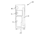
図3、図4及び図5に、デジタルカメラ10Aの内部配置図を示す。図3は、デジタルカメラ10Aの正面図であり、どのように固定焦点距離レンズサブアセンブリ1aとズームレンズサブアセンブリ1bがレンズ2,3の一方側に位置し電子フラッシュ48の下部に位置するかを示す。バッテリ部204は、レンズ2,3の他方側に位置する。図4はデジタルカメラ10Aの平面図で図3のIV−IVラインから見た図であり、さらにメモリカード54とカラーLCD70を示す。図5はデジタルカメラ10Aの側面図で図4のV−Vラインから見た図であり、さらに固定焦点距離レンズサブアセンブリ1a、ズームレンズサブアセンブリ1b、フラッシュ48の垂直方向位置を示す。特に注目すべきは、サブアセンブリ1a、1bの備える屈曲光学系により撮像アセンブリ1がカメラ10Aの前面(フロント)から背面(リア)に至るコンパクトなサイズ210内に収納できることである。
3, 4 and 5 show the internal arrangement of the
図6A及び図6Bに、屈曲光路に沿ってイメージセンサ12との関係で固定焦点距離レンズ2を支持する光学中継サブアセンブリ1aを示す。図6Aは固定焦点距離レンズ2の対物レンズ、イメージセンサ12、ミラープリズム8aにより屈曲される光路上の中継レンズ部品7aを支持するレンズ鏡筒6aを示す。加えて、レンズ鏡筒6aは光路上の絞りシャッタアセンブリ9aを支持する。図6Bは図6AにおけるVIB−VIBラインから見た図でカメラの正面から見た光学サブアセンブリ1aの外観を示す。
6A and 6B show an optical relay subassembly 1a that supports the fixed
図7に、屈曲光路に沿ってイメージセンサ14との関係でズームレンズ3を支持する、光学中継サブアセンブリ1bを示す。サブアセンブリ1bは、ズームレンズ3の対物レンズ、第2イメージセンサ14、ミラープリズム8bにより屈曲される光路上の移動可能な中継(ズーム)レンズ部品7bを支持する取付具6bを含む。取付具6bは光路上の絞りシャッタアセンブリ9bを支持する。レンズ部品7bの移動はズーム及びフォーカスモータ5aで制御される。
FIG. 7 shows an
このような構成において、基本的な動作は以下のとおりである。パワースイッチを用いてデジタルカメラ10AがONされると、ズームレンズ3はデフォルト位置に設定される。デフォルト位置は好適にはワイド端、すなわちズームレンズ3の最小焦点距離IIOW
である。ユーザがパノラマボタン42bを押すと、制御プロセッサ及びタイミングジェネレータ40はアナログMUX34を制御してアナログ信号プロセッサ(ASP1)22を用い、第1イメージセンサ12の出力がA/D変換器36に供給される。そして、イメージセンサ12からのプレビュー画像がLCD70に表示される。ここでズームボタンが操作されると、固定焦点距離レンズ(広角レンズ)2の電子ズームが実行される。次に、シャッタボタン42aが押されると、第1センサ12の出力を用いて静止画像(スチル画像)が撮影されメモリカード54に記憶される。
In such a configuration, the basic operation is as follows. When the
It is. When the user presses the
ユーザがパノラマボタン42bを押さない場合、制御プロセッサ及びタイミングジェネレータ40はアナログマルチプレクサ34を制御してアナログ信号プロセッサ(ASP2)24を用い、第2イメージセンサ14の出力がA/D変換器36に供給される。そして、第2イメージセンサ14からのプレビュー画像がLCD70に表示される。ここでズームボタンが操作されると、ズーム調整ステップ108においてズームレンズの位置が調整され、ズームレンズ3のワイド端からテレ端までのズーム効果が得られる。次に、シャッタボタンが押されると、撮影ステップ110にて第2イメージセンサ14の出力を用いて静止画像が撮影される。
When the user does not press the
一方、ユーザがパノラマボタン42bを押して第1イメージセンサ12からのデジタル画像を取得し、その後、ユーザがズームボタン42cの「テレ」側を操作し続ける場合、あるいは、ユーザがパノラマボタン42bを操作しないために第2イメージセンサ14からのデジタル画像が取得され、その後、ユーザがズームボタン42cの「ワイド」側を操作し続ける場合、2つの光学系の切り替わりが生じる。本実施形態では、固定焦点距離レンズ2の電子ズーム範囲700とズームレンズ3の光学ズーム範囲800を、その一部が互いに重複するように設定する。
On the other hand, when the user presses the
図8に、本実施形態の固定焦点距離レンズ2の電子ズーム範囲700及びズームレンズ3の光学ズーム範囲800を示す。固定焦点距離レンズ2の電子ズーム範囲700は、単に固定焦点距離レンズ2とズームレンズ3との間の焦点距離ギャップを埋めるだけでなく、ズームレンズ3のズーム範囲800の一部にオーバラップしてオーバラップ範囲750を形成している。固定焦点距離レンズ2の電子ズーム範囲700のワイド端をIDT、テレ端をIDT-1、ズームレンズ3の光学ズーム範囲800のワイド端をIIOW-1、テレ端をIIOTとすると、IDWはIIOW-1よりもワイド側に位置し、IDT-1はIIOTよりワイド側に位置するとともにIIOW-1よりテレ側に位置する。
FIG. 8 shows an
ワイド側からテレ側に遷移する場合、オーバラップ範囲750の任意の位置で切り替えることができるが、例えば電子ズーム範囲700のテレ端IDT-1で切り替えることができる。また、テレ側からワイド側に遷移する場合も、オーバラップ範囲750の任意の位置で切り替えることができるが、例えば光学ズーム範囲800のワイド端IIOW-1で切り替えることができる。
When transitioning from the wide side to the tele side, switching can be performed at an arbitrary position in the
ズーム及びフォーカスモータ5aは、ズームレンズ3をステップ的に、あるいは離散的に駆動する。従って、ズームレンズ3の光学ズーム範囲800も連続ではなく、ステップ的あるいは離散的である。ユーザがズームボタン42cを操作して設定したズーム位置がズームレンズ3の離散的な光学ズーム位置に一致する場合には問題ないが、ユーザの設定したズーム位置がズームレンズ3の離散的な光学ズーム位置に一致しない、すなわちズームボタン42cは連続的またはズームレンズ3の光学ズームのステップ幅よりも細かい幅でズーム位置(画角)を設定することができ、ユーザの設定したズーム位置(画角)が離散的な光学ズーム位置の間に存在するような場合、固定焦点距離レンズ2の電子ズームで補うことができるが、既に述べたように電子ズームで得られる画像が画質劣化を招く。そこで、本実施形態では、ユーザの設定したズーム位置がオーバラップ範囲750内に位置し、かつ、離散的な光学ズームの間に存在する場合に、固定焦点距離レンズ2とズームレンズ3をともに用いて撮影を行う。
The zoom and focus motor 5a drives the
なお、ユーザの設定したズーム位置が電子ズーム範囲700のみに位置する場合には電子ズームを実行して撮影し、光学ズーム範囲800のみに位置する場合には光学ズームのズーム位置のうち設定されたズーム位置の直近のステップにおいて撮影する。ユーザの設定したズーム位置が光学ズーム範囲800のみに位置する場合でも下記に示すように光学ズームが指定されたズーム位置を通過する時点で撮影することも可能である。
When the zoom position set by the user is located only in the
図9A、図9B及び図9Cに、ユーザがズームボタン42cを「ワイド」側に設定した場合の、固定焦点距離レンズ2の電子ズーム及びズームレンズ3の光学ズームを示す。なお、これらの図には固定焦点距離レンズ2の焦点距離及びズームレンズ3の焦点距離が模式的に示されている。また、電子ズーム範囲700と光学ズーム範囲800のオーバラップ範囲750を例えば40mm−80mmとする。
9A, 9B, and 9C show the electronic zoom of the fixed
図9Aに、ユーザがズームボタン42cを「ワイド」側に操作してズーム位置を焦点距離45mm近傍に設定した場合を示す。図において、印900がユーザの設定したズーム位置を示す。ズームレンズ3は焦点距離80mmのズーム位置に設定されているものとする。このとき、電子ズームの駆動速度と光学ズームの駆動速度では電子ズームの駆動速度の方が早いため、制御プロセッサ及びタイミングジェネレータ40は第1イメージセンサ12の出力を選択し、画像プロセッサ50に供給する。画像プロセッサ50は、第1イメージセンサ12からのデジタル画像を電子的にズームし、LCD70に表示する。
FIG. 9A shows a case where the user operates the
図9Bに、電子ズームを実行した場合を示す。図において、印910が電子ズームのズーム位置を示す。この電子ズーム位置はユーザの設定したズーム位置に一致する。LCD70には第1イメージセンサ12で得られたデジタル画像を電子ズームした画像が表示されるためその画角はユーザの意図した画角であるが、画質は劣る。この状態でユーザがシャッタボタン42aを操作すると、電子ズーム画像がメモリカード54に記憶されることとなる。本実施形態では、制御プロセッサ及びタイミングジェネレータ40は、電子ズーム画像に代えて、あるいは電子ズーム画像とともに、光学ズーム画像も取得してメモリカード54に記憶する。
FIG. 9B shows a case where electronic zoom is executed. In the figure, a
図9Cに、電子ズームを実行した後のズームレンズ3の駆動状態を示す。ズーム及びフォーカスモータ5aは、制御プロセッサ及びタイミングジェネレータ40からの指令に従い、ズームレンズ3をユーザにより設定されたズーム位置900に向けて駆動する。ズームレンズ3は離散的に駆動される。図において、印4はズームレンズ3の離散的なズーム位置を示す。ズームレンズ3はユーザ設定ズーム位置900で停止できないものの、ユーザ設定位置900を通過する。制御プロセッサ及びタイミングジェネレータ40は、ズームレンズ3がユーザ設定ズーム位置900を通過する時点で第2イメージセンサ14で得られたデジタル画像を画像プロセッサ50に供給し、画像プロセッサ50はデジタル画像を処理してメモリカード54に記憶する。したがって、LCD70には電子ズーム画像が表示されるものの、撮影されメモリカード54に記憶される画像は光学ズーム画像だけ、あるいは電子ズーム画像及び光学ズーム画像となる。
FIG. 9C shows a driving state of the
図13に、上記した処理のフローチャートを示す。ユーザがズームボタン42cを操作すると(ズームボタンオン)、制御プロセッサ及びタイミングジェネレータ40と画像プロセッサ50は固定焦点距離レンズ2の電子ズームを動作させ(S101)、第1イメージセンサ12の画像を電子的に拡大して得られた画像をLCD70に表示する(S102)。ユーザは、所望の画角をLCD70で確認することができる。一方、制御プロセッサ及びタイミングジェネレータ40はズーム及びフォーカスモータ5aを駆動してズームレンズ3のステップ位置のうち、電子ズームのズーム位置(画角)に最も近傍のステップ位置にズームレンズ3の光学ズームを制御する(S103)。そして、この状態で待機しつつシャッタボタンが操作されたか否かを判定する(S104)。シャッタボタンが操作されると、制御プロセッサ及びタイミングジェネレータ40はズームレンズ3の光学ズームを待機位置から固定焦点距離レンズ2の電子ズーム画角側に向けて1ステップだけ移動させ(S105)、光学ズームの画角が電子ズームの画角と一致した時点で(S106でYES)、光学ズームの画像、すなわち第2イメージセンサ14で得られた画像をメモリカード54に記憶する(S107)。
FIG. 13 shows a flowchart of the above processing. When the user operates the
以上はユーザがズームボタン42cを「ワイド」側に操作した場合であるが、「テレ」側に操作した場合も同様である。
The above is the case where the user operates the
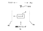
図10に、ユーザ設定ズーム位置900(すなわち電子ズーム位置910)近傍の光学ズーム位置を示す。ズームレンズ3は離散的なズーム位置4a、4bで停止できるが、その間のユーザ設定ズーム位置900には停止できず通過する。ズーム及びフォーカスモータ5aは、ズームレンズ3がユーザ設定ズーム位置900の直前のズーム位置4aに達した時点のフォーカスをそのまま維持してズームレンズ3を直後のズーム位置4bまで駆動する。制御プロセッサ及びタイミングジェネレータ40は、ズームレンズ3がユーザ設定ズーム位置を通過した時点の第2イメージセンサ14からのデジタル画像をメモリカード54に記憶する(図において、撮影タイミングtsを示す)。ズームレンズ3でユーザ設定ズーム位置900を通過した時点で撮影した後、ズーム及びフォーカスモータ5aはズームレンズ3を直後のズーム位置4bに停止させる。ユーザが「テレ」側に操作した場合、直前のズーム位置4bでのフォーカスを維持してユーザ設定ズーム位置900で撮影し、直後のズーム位置4aでズームレンズ3を停止させる。
FIG. 10 shows an optical zoom position near the user-set zoom position 900 (that is, the electronic zoom position 910). The
図11に、他の実施形態におけるユーザ設定ズーム位置900近傍の光学ズーム位置を示す。図10では、ズームレンズ3がユーザ設定ズーム位置900を通過した時点を撮影タイミングtsとしている。図11は、オートブラケッティング撮影を行う場合を示す。通常、オートブラケッティング撮影では、適正と思われる露出に対し、アンダに補正した露出、及びオーバに補正した露出で連続的に被写体を撮影する。ユーザは、これら複数の異なる露出で撮影した画像の中から好みの露出の画像を選択することができる。図11では、露出を異にするのではなく、ズーム位置(画角)を異にする複数の光学ズーム画像を撮影する。ズーム及びフォーカスモータ5aは、ズームレンズ3をユーザ設定ズーム位置900に向けて離散的に駆動する。ズームレンズ3がユーザ設定ズーム位置900の直前のズーム位置4aに達した時点でズームレンズ3を停止させ、まず電子ズーム画像をメモリに記憶し、次に被写体を撮影する。その後、ズームレンズ3を再び駆動し、ズームレンズ3がユーザ設定ズーム位置900を通過した時点で被写体を撮影する。その後、ズームレンズがユーザ設定ズーム位置900の直後のズーム位置4bに達した時点でズームレンズ3を停止させ、被写体を撮影する(図において、3回の撮影タイミングtsを示す)。以上のようにして、ユーザによる1回のシャッタボタン42aの操作及びユーザによるズームボタン42cの操作により、互いにズーム位置の異なる3つの画像が得られ、メモリカード54に記憶される(オートズームブラケッティング撮影)。この間、LCD70には電子ズーム画像が表示される。これにより、時間的にずれた画像を取り込むことができ、比較選択することができる。
FIG. 11 shows an optical zoom position in the vicinity of the user-set
図11では、ユーザ設定ズーム位置、直前の離散的なズーム位置4a、直後の離散的なズーム位置4bの3つの画像を取得しているが、通常のオートブラケッティング撮影と同様に、撮影枚数を適宜ユーザが設定してもよい。
In FIG. 11, three images of the user-set zoom position, the immediately preceding
図12に、デジタルカメラ10Aに1つの固定焦点距離レンズ及び2つのズームレンズを搭載する場合の、それぞれのズームレンズの光学ズーム範囲800−2、800−3、及び電子ズーム範囲700−1、700−2、700−3を示す。図1に示す2つの撮像光学系を備えるデジタルカメラ10Aにおいて、さらに第3のズームレンズを付加して3つの撮像光学系としたデジタルカメラである。第1のレンズは20mmの固定焦点距離レンズであり、第1の電子ズーム範囲700−1を有する。第2のレンズは40mm−80mmのズームレンズであり、第2の光学ズーム範囲800−2及び第2の電子ズーム範囲700−2を有する。第3のレンズは160mm−320mmのズームレンズであり、第3の光学ズーム範囲800−3及び第3の電子ズーム範囲700−3を有する。第1のレンズの第1電子ズーム範囲700−1と第2のレンズの第2光学ズーム範囲の関係は上述した固定焦点距離レンズ2の電子ズーム範囲700とズームレンズ3の光学ズーム範囲800との関係と同一である。第2のレンズの第2電子ズーム範囲700−2と第3のレンズの第3光学ズーム範囲800−3との関係も同様であり、両ズーム範囲は互いに一部がオーバラップするように設定される。すなわち、第2のレンズの第2電子ズーム範囲700−2のテレ端は第3のレンズの第3光学ズーム範囲800−3のワイド端よりもテレ側にあり、第3光学ズーム範囲800−3のテレ端よりもワイド側にある。また、第2のレンズの第2電子ズーム範囲700−2のワイド端は第3のレンズの第3光学ズーム範囲800−3のワイド端よりもワイド側にある。ユーザの設定したズーム位置が第2電子ズーム範囲と第3光学ズーム範囲のオーバラップ範囲内に存在する場合、上記の実施形態と同様にまず電子ズームで画像を取得してLCD70に表示し、その後、光学ズームを離散的に駆動して対応するズーム位置を通過する時点で撮影し、得られた画像をメモリカード54に記憶する。
FIG. 12 shows an optical zoom range 800-2 and 800-3 and an electronic zoom range 700-1 and 700 of each zoom lens when one fixed focal length lens and two zoom lenses are mounted on the digital camera 10A. -2 and 700-3. In the
以上、本発明の実施形態について説明したが、本発明はこれらの態様に限定されるものではなく、その他の態様も可能である。 As mentioned above, although embodiment of this invention was described, this invention is not limited to these aspects, Other aspects are also possible.
例えば、本実施形態では、2つの撮像光学系あるいは3つの撮像光学系を有するデジタルカメラを例示したが、単一の撮像光学系を有するデジタルカメラに適用してもよい。このようなデジタルカメラは、単一のズームレンズのみを備え、電子ズーム機能及び光学ズーム機能を有する。光学ズームはフォーカス及びズームモータにより離散的に駆動される。ユーザの設定したズーム位置が離散的なズーム位置の間に存在する場合に、まず電子ズームをユーザ設定ズーム位置に設定してLCD70に表示する。その後、光学ズームを駆動し、ユーザ設定ズーム位置直前の離散的なズーム位置におけるフォーカスを維持し、光学ズームがユーザ設定ズーム位置を通過する時点で撮影して得られた画像をメモリカード54に記憶する。その後、ズームレンズの光学ズーム位置は、ユーザ設定ズーム位置直後の離散的なズーム位置に停止する。単一のズームレンズのみを備え、光学ズーム機能のみを有するデジタルカメラに適用してもよい。電子ズームを行うことなく、光学ズームで得られた画像を光学ファインダに表示し、光学ズームがユーザ設定ズーム位置を通過する時点で撮影する。
For example, in the present embodiment, a digital camera having two imaging optical systems or three imaging optical systems has been exemplified, but the present invention may be applied to a digital camera having a single imaging optical system. Such a digital camera includes only a single zoom lens and has an electronic zoom function and an optical zoom function. The optical zoom is discretely driven by a focus and zoom motor. When the zoom position set by the user exists between the discrete zoom positions, the electronic zoom is first set to the user-set zoom position and displayed on the
また、本実施形態では、電子ズーム画像をLCD70に表示し、この表示を維持したまま光学ズーム画像を取得してメモリカード54に記憶しているが、以下のような態様が可能である。
(1)LCD70に電子ズーム画像を表示し、撮影して得られた光学ズーム画像のみをメモリカード54に記憶する
(2)LCD70に電子ズーム画像を表示し、撮影して得られた電子ズーム画像及び光学ズーム画像をメモリカード54に記憶する
(3)LCD70に電子ズーム画像を表示し、撮影して得られた光学ズーム画像をメモリカード54に記憶するとともにLCD70に電子ズーム画像に代えて表示する
In this embodiment, the electronic zoom image is displayed on the
(1) An electronic zoom image is displayed on the
また、図11では、ユーザ設定ズーム位置900、離散的ズーム位置4a、離散的ズーム位置4bにおいて撮影しているが、ユーザ設定ズーム位置900と離散的ズーム位置4aにおいて計2回撮影してもよく、あるいはユーザ設定ズーム位置900と離散的ズーム位置4bにおいて計2回撮影してもよい。さらに、ユーザ設定ズーム位置900を含んで設定枚数だけワイド側、あるいはテレ側にズーム位置がシフトした画像を取得してもよい。また、本実施形態では固定焦点距離レンズ2を用いているが、2つの撮像光学系をともにズームレンズとしてもよい。
Further, in FIG. 11, the images are taken at the user setting
また、本実施形態では、ユーザがズームボタン42cを操作して画角を指定し、シャッタボタン42aを操作して撮影指令を入力する構成であるが、他の制御ユニットからの信号に応じて画角やシャッタが制御される構成でもよい。
In this embodiment, the user designates the angle of view by operating the
2 固定焦点距離レンズ、3 ズームレンズ、12 第1イメージセンサ、14 第2イメージセンサ、40 制御プロセッサ及びタイミングジェネレータ、42 ユーザコントロール、48 フラッシュ、50 画像プロセッサ、54 リムーバブルメモリカード、70 カラーLCD。 2 fixed focal length lens, 3 zoom lens, 12 first image sensor, 14 second image sensor, 40 control processor and timing generator, 42 user control, 48 flash, 50 image processor, 54 removable memory card, 70 color LCD.
Claims (4)
前記ズームの画角を指定する画角指定手段と、
撮影指令を行う撮影指令手段と、
前記撮影指令がなされると、前記撮像光学系の光学ズームを前記指定された画角方向にステップ駆動し、前記光学ズームが前記指定された画角を通過する時点で前記撮像光学系を用いて被写体画像を記録する制御手段と、
を有し、
前記画角指定手段は連続的または前記ステップ駆動の幅よりも細かい幅で画角を指定する手段であり、
前記制御手段は前記撮像光学系のステップ位置を前記指定された画角の近傍に追従するように制御し、前記撮影指令がなされると前記撮像光学系の光学ズームを前記近傍のステップ位置から前記指定された画角方向にステップ駆動し、前記光学ズームが前記指定された画角を通過する時点で前記被写体画像を記録することを特徴とする撮像装置。 An imaging optical system in which the angle of view of the zoom is step-driven,
An angle-of-view specifying means for specifying the angle of view of the zoom;
A shooting command means for issuing a shooting command;
When the shooting command is issued, the optical zoom of the imaging optical system is step-driven in the designated angle of view, and the optical zoom is used when the optical zoom passes the designated angle of view. Control means for recording a subject image;
I have a,
The angle-of-view specifying means is means for specifying the angle of view continuously or with a width smaller than the width of the step drive,
The control means controls the step position of the imaging optical system so as to follow the vicinity of the designated angle of view, and when the shooting command is given, the optical zoom of the imaging optical system is changed from the step position of the vicinity. An image pickup apparatus that is step-driven in a designated field angle direction and records the subject image when the optical zoom passes the designated field angle .
前記指定された画角に応じたズーム画像を表示する表示手段と、
を有することを特徴とする撮像装置。 The apparatus of claim 1, further comprising:
Display means for displaying a zoom image according to the specified angle of view;
An imaging device comprising:
前記指定された画角に応じた電子ズーム画像を生成する手段と、
を有し、前記表示手段は前記電子ズーム画像を表示することを特徴とする撮像装置。 The apparatus of claim 2, further comprising:
Means for generating an electronic zoom image corresponding to the specified angle of view;
And the display means displays the electronic zoom image.
前記制御手段は前記指定された画角の近傍のステップ位置においても被写体画像を記録することを特徴とする撮像装置。 The apparatus of claim 1.
The image pickup apparatus, wherein the control means records a subject image even at a step position in the vicinity of the designated angle of view.
Priority Applications (2)
| Application Number | Priority Date | Filing Date | Title |
|---|---|---|---|
| JP2005344624A JP4624245B2 (en) | 2005-11-29 | 2005-11-29 | Imaging device |
| US11/410,970 US7397609B2 (en) | 2005-11-29 | 2006-04-25 | Imaging apparatus |
Applications Claiming Priority (1)
| Application Number | Priority Date | Filing Date | Title |
|---|---|---|---|
| JP2005344624A JP4624245B2 (en) | 2005-11-29 | 2005-11-29 | Imaging device |
Publications (3)
| Publication Number | Publication Date |
|---|---|
| JP2007150903A JP2007150903A (en) | 2007-06-14 |
| JP2007150903A5 JP2007150903A5 (en) | 2008-12-11 |
| JP4624245B2 true JP4624245B2 (en) | 2011-02-02 |
Family
ID=38087036
Family Applications (1)
| Application Number | Title | Priority Date | Filing Date |
|---|---|---|---|
| JP2005344624A Active JP4624245B2 (en) | 2005-11-29 | 2005-11-29 | Imaging device |
Country Status (2)
| Country | Link |
|---|---|
| US (1) | US7397609B2 (en) |
| JP (1) | JP4624245B2 (en) |
Families Citing this family (18)
| Publication number | Priority date | Publication date | Assignee | Title |
|---|---|---|---|---|
| TWI318071B (en) * | 2006-08-28 | 2009-12-01 | Avision Inc | Image-acquiring device |
| US8432465B2 (en) * | 2006-09-25 | 2013-04-30 | Siemens Medical Solutions Usa, Inc. | System and method for establishing zoom settings for display of an anatomical image |
| JP4767838B2 (en) * | 2006-12-28 | 2011-09-07 | 三星電子株式会社 | Imaging apparatus and imaging method |
| JP5043635B2 (en) * | 2007-12-28 | 2012-10-10 | キヤノン株式会社 | Imaging device |
| JP5381060B2 (en) * | 2008-02-05 | 2014-01-08 | 株式会社リコー | Imaging apparatus and image processing method thereof |
| KR101610705B1 (en) | 2008-12-10 | 2016-04-11 | 삼성전자주식회사 | Terminal having camera and method for processing image thereof |
| US8542287B2 (en) * | 2009-03-19 | 2013-09-24 | Digitaloptics Corporation | Dual sensor camera |
| US8553106B2 (en) * | 2009-05-04 | 2013-10-08 | Digitaloptics Corporation | Dual lens digital zoom |
| JP5950492B2 (en) * | 2010-08-05 | 2016-07-13 | キヤノン株式会社 | Control apparatus and control method |
| WO2013047159A1 (en) * | 2011-09-28 | 2013-04-04 | 富士フイルム株式会社 | Imaging device |
| WO2013099169A1 (en) | 2011-12-27 | 2013-07-04 | パナソニック株式会社 | Stereo photography device |
| JP2013143753A (en) | 2012-01-12 | 2013-07-22 | Olympus Corp | Imaging apparatus |
| WO2014190065A1 (en) * | 2013-05-21 | 2014-11-27 | Sony Corporation | Post production replication of optical processing for digital cinema cameras using metadata |
| TWI554103B (en) * | 2014-11-13 | 2016-10-11 | 聚晶半導體股份有限公司 | Image capturing device and digital zooming method thereof |
| US10142533B2 (en) * | 2015-03-27 | 2018-11-27 | Intel Corporation | Technologies for controlling user access to image sensors of a camera device |
| CN107852453B (en) | 2015-07-10 | 2020-06-23 | 深圳市大疆创新科技有限公司 | Dual lens system with beam splitter |
| CN107219710B (en) * | 2016-03-21 | 2020-12-08 | 深圳富泰宏精密工业有限公司 | Multi-lens system and portable electronic device with same |
| CN107766784A (en) * | 2016-08-20 | 2018-03-06 | 宋坤骏 | A kind of novel video people counting algorithm |
Citations (4)
| Publication number | Priority date | Publication date | Assignee | Title |
|---|---|---|---|---|
| JPH05191704A (en) * | 1992-01-16 | 1993-07-30 | Olympus Optical Co Ltd | Electronic image pickup device |
| JP2002033951A (en) * | 2000-07-18 | 2002-01-31 | Casio Comput Co Ltd | Electronic camera and photographing method |
| JP2004153538A (en) * | 2002-10-30 | 2004-05-27 | Fuji Photo Film Co Ltd | Digital camera with zooming function |
| JP2005308777A (en) * | 2004-04-16 | 2005-11-04 | Casio Comput Co Ltd | Photographing apparatus and its program |
Family Cites Families (7)
| Publication number | Priority date | Publication date | Assignee | Title |
|---|---|---|---|---|
| JPH0818842A (en) | 1994-06-30 | 1996-01-19 | Sony Corp | Video camera |
| JPH104218A (en) | 1996-06-14 | 1998-01-06 | Isuzu Motors Ltd | Porous structure thermoelectric element and manufacture thereof |
| JPH1010405A (en) * | 1996-06-19 | 1998-01-16 | Canon Inc | Lens device and image pickup device |
| JPH1042183A (en) * | 1996-07-22 | 1998-02-13 | Canon Inc | Image pickup device |
| JP2002314868A (en) * | 2001-04-13 | 2002-10-25 | Olympus Optical Co Ltd | Imaging device |
| JP3678205B2 (en) | 2002-03-27 | 2005-08-03 | コニカミノルタフォトイメージング株式会社 | Digital camera |
| JP4348261B2 (en) * | 2004-08-31 | 2009-10-21 | Hoya株式会社 | Trimming imaging device |
-
2005
- 2005-11-29 JP JP2005344624A patent/JP4624245B2/en active Active
-
2006
- 2006-04-25 US US11/410,970 patent/US7397609B2/en active Active
Patent Citations (4)
| Publication number | Priority date | Publication date | Assignee | Title |
|---|---|---|---|---|
| JPH05191704A (en) * | 1992-01-16 | 1993-07-30 | Olympus Optical Co Ltd | Electronic image pickup device |
| JP2002033951A (en) * | 2000-07-18 | 2002-01-31 | Casio Comput Co Ltd | Electronic camera and photographing method |
| JP2004153538A (en) * | 2002-10-30 | 2004-05-27 | Fuji Photo Film Co Ltd | Digital camera with zooming function |
| JP2005308777A (en) * | 2004-04-16 | 2005-11-04 | Casio Comput Co Ltd | Photographing apparatus and its program |
Also Published As
| Publication number | Publication date |
|---|---|
| US20070120988A1 (en) | 2007-05-31 |
| JP2007150903A (en) | 2007-06-14 |
| US7397609B2 (en) | 2008-07-08 |
Similar Documents
| Publication | Publication Date | Title |
|---|---|---|
| JP4624245B2 (en) | Imaging device | |
| US7509041B2 (en) | Image-capturing device having multiple optical systems | |
| US7738016B2 (en) | Digital camera with dual optical systems | |
| US7561191B2 (en) | Camera phone using multiple lenses and image sensors to provide an extended zoom range | |
| US7256944B2 (en) | Compact image capture assembly using multiple lenses and image sensors to provide an extended zoom range | |
| US7305180B2 (en) | Digital camera using multiple lenses and image sensors to provide an extended zoom range | |
| US7236306B2 (en) | Digital camera using an express zooming mode to provide expedited operation over an extended zoom range | |
| JP4405069B2 (en) | Image resolution maximization method | |
| US20060187322A1 (en) | Digital camera using multiple fixed focal length lenses and multiple image sensors to provide an extended zoom range | |
| US7515197B2 (en) | Digital camera capable of obtaining crop image | |
| JP2007081473A (en) | Imaging apparatus having plural optical system | |
| JP2007221386A (en) | Imaging apparatus | |
| JP4652998B2 (en) | Imaging device | |
| JP2007142702A (en) | Image processing apparatus | |
| JP2011091636A (en) | Image capturing apparatus | |
| JP4977569B2 (en) | Imaging control apparatus, imaging control method, imaging control program, and imaging apparatus | |
| JP2008199210A (en) | Photographing device and photographing method | |
| JP2006287735A (en) | Picture voice recording apparatus and collecting voice direction adjustment method | |
| JP4341019B2 (en) | Imaging apparatus and program | |
| JP2005308777A (en) | Photographing apparatus and its program | |
| JP2007316471A (en) | Imaging apparatus and program therefore | |
| JP2011186375A (en) | Photographing device, photographing method, and program | |
| JP2000224455A (en) | Digital camera provided with improved zooming function and method therefor | |
| JP5077113B2 (en) | Electronic camera | |
| JP2004354439A (en) | Digital camera |
Legal Events
| Date | Code | Title | Description |
|---|---|---|---|
| A521 | Request for written amendment filed |
Free format text: JAPANESE INTERMEDIATE CODE: A523 Effective date: 20081027 |
|
| A621 | Written request for application examination |
Free format text: JAPANESE INTERMEDIATE CODE: A621 Effective date: 20081027 |
|
| A977 | Report on retrieval |
Free format text: JAPANESE INTERMEDIATE CODE: A971007 Effective date: 20100628 |
|
| A131 | Notification of reasons for refusal |
Free format text: JAPANESE INTERMEDIATE CODE: A131 Effective date: 20100706 |
|
| A521 | Request for written amendment filed |
Free format text: JAPANESE INTERMEDIATE CODE: A523 Effective date: 20100929 |
|
| TRDD | Decision of grant or rejection written | ||
| A01 | Written decision to grant a patent or to grant a registration (utility model) |
Free format text: JAPANESE INTERMEDIATE CODE: A01 Effective date: 20101019 |
|
| A01 | Written decision to grant a patent or to grant a registration (utility model) |
Free format text: JAPANESE INTERMEDIATE CODE: A01 |
|
| A61 | First payment of annual fees (during grant procedure) |
Free format text: JAPANESE INTERMEDIATE CODE: A61 Effective date: 20101102 |
|
| R150 | Certificate of patent or registration of utility model |
Ref document number: 4624245 Country of ref document: JP Free format text: JAPANESE INTERMEDIATE CODE: R150 Free format text: JAPANESE INTERMEDIATE CODE: R150 |
|
| FPAY | Renewal fee payment (event date is renewal date of database) |
Free format text: PAYMENT UNTIL: 20131112 Year of fee payment: 3 |
|
| S111 | Request for change of ownership or part of ownership |
Free format text: JAPANESE INTERMEDIATE CODE: R313113 |
|
| R350 | Written notification of registration of transfer |
Free format text: JAPANESE INTERMEDIATE CODE: R350 |
|
| R250 | Receipt of annual fees |
Free format text: JAPANESE INTERMEDIATE CODE: R250 |
|
| R250 | Receipt of annual fees |
Free format text: JAPANESE INTERMEDIATE CODE: R250 |
|
| R250 | Receipt of annual fees |
Free format text: JAPANESE INTERMEDIATE CODE: R250 |
|
| R250 | Receipt of annual fees |
Free format text: JAPANESE INTERMEDIATE CODE: R250 |
|
| R250 | Receipt of annual fees |
Free format text: JAPANESE INTERMEDIATE CODE: R250 |
|
| R250 | Receipt of annual fees |
Free format text: JAPANESE INTERMEDIATE CODE: R250 |
|
| R250 | Receipt of annual fees |
Free format text: JAPANESE INTERMEDIATE CODE: R250 |
|
| R250 | Receipt of annual fees |
Free format text: JAPANESE INTERMEDIATE CODE: R250 |
|
| R250 | Receipt of annual fees |
Free format text: JAPANESE INTERMEDIATE CODE: R250 |
|
| R250 | Receipt of annual fees |
Free format text: JAPANESE INTERMEDIATE CODE: R250 |