JP2007142702A - Image processing apparatus - Google Patents
Image processing apparatus Download PDFInfo
- Publication number
- JP2007142702A JP2007142702A JP2005332412A JP2005332412A JP2007142702A JP 2007142702 A JP2007142702 A JP 2007142702A JP 2005332412 A JP2005332412 A JP 2005332412A JP 2005332412 A JP2005332412 A JP 2005332412A JP 2007142702 A JP2007142702 A JP 2007142702A
- Authority
- JP
- Japan
- Prior art keywords
- image
- blur
- added
- amount
- image blur
- Prior art date
- Legal status (The legal status is an assumption and is not a legal conclusion. Google has not performed a legal analysis and makes no representation as to the accuracy of the status listed.)
- Pending
Links
- 238000012545 processing Methods 0.000 title claims abstract description 120
- 238000005304 joining Methods 0.000 claims abstract description 17
- 238000000034 method Methods 0.000 claims description 61
- 230000008859 change Effects 0.000 claims description 55
- 230000008569 process Effects 0.000 claims description 55
- 238000003384 imaging method Methods 0.000 description 86
- 230000003287 optical effect Effects 0.000 description 68
- 230000004048 modification Effects 0.000 description 29
- 238000012986 modification Methods 0.000 description 29
- 238000006243 chemical reaction Methods 0.000 description 28
- 238000007906 compression Methods 0.000 description 20
- 238000001514 detection method Methods 0.000 description 19
- 238000000605 extraction Methods 0.000 description 18
- 230000002829 reductive effect Effects 0.000 description 18
- 230000006835 compression Effects 0.000 description 15
- 238000003825 pressing Methods 0.000 description 15
- 239000000428 dust Substances 0.000 description 11
- 230000004044 response Effects 0.000 description 11
- 239000013598 vector Substances 0.000 description 11
- 238000009825 accumulation Methods 0.000 description 10
- 230000007423 decrease Effects 0.000 description 9
- 230000003247 decreasing effect Effects 0.000 description 9
- 230000006837 decompression Effects 0.000 description 8
- 230000003321 amplification Effects 0.000 description 7
- 238000003199 nucleic acid amplification method Methods 0.000 description 7
- 238000010586 diagram Methods 0.000 description 6
- 230000000694 effects Effects 0.000 description 6
- 238000011156 evaluation Methods 0.000 description 6
- 230000036961 partial effect Effects 0.000 description 6
- 238000005375 photometry Methods 0.000 description 6
- 230000009467 reduction Effects 0.000 description 5
- 238000004364 calculation method Methods 0.000 description 4
- 230000006866 deterioration Effects 0.000 description 4
- 230000015556 catabolic process Effects 0.000 description 3
- 239000002131 composite material Substances 0.000 description 3
- 238000006731 degradation reaction Methods 0.000 description 3
- 230000001133 acceleration Effects 0.000 description 2
- 238000012790 confirmation Methods 0.000 description 2
- 238000009826 distribution Methods 0.000 description 2
- 239000000284 extract Substances 0.000 description 2
- 238000001454 recorded image Methods 0.000 description 2
- 230000002194 synthesizing effect Effects 0.000 description 2
- 238000009966 trimming Methods 0.000 description 2
- 238000013459 approach Methods 0.000 description 1
- 239000003086 colorant Substances 0.000 description 1
- 238000004040 coloring Methods 0.000 description 1
- 230000000295 complement effect Effects 0.000 description 1
- 238000012937 correction Methods 0.000 description 1
- 230000001934 delay Effects 0.000 description 1
- 230000003111 delayed effect Effects 0.000 description 1
- 238000005516 engineering process Methods 0.000 description 1
- 238000013213 extrapolation Methods 0.000 description 1
- 210000000887 face Anatomy 0.000 description 1
- 238000005286 illumination Methods 0.000 description 1
- 230000007246 mechanism Effects 0.000 description 1
- 238000010606 normalization Methods 0.000 description 1
- 210000001747 pupil Anatomy 0.000 description 1
- 238000011946 reduction process Methods 0.000 description 1
- 230000011514 reflex Effects 0.000 description 1
- 230000000717 retained effect Effects 0.000 description 1
- 230000002441 reversible effect Effects 0.000 description 1
- 230000000007 visual effect Effects 0.000 description 1
Images


Abstract
Description
本発明は、画像にぼかしを付加する画像処理装置に関する。 The present invention relates to an image processing apparatus that adds blur to an image.
35mm版カメラに比べて撮像面積が小さい電子カメラが普及している。このタイプのカメラは実焦点距離が短いため、35mm版カメラの場合と同じF値(光学絞り値)の撮影レンズを用いても、35mm版カメラのように背景をぼかした撮影画像が得られにくい。特許文献1には、画像処理によって画像にぼかしを付加する技術が開示されている。 Electronic cameras that have a smaller imaging area compared to 35 mm cameras have become widespread. Since this type of camera has a short actual focal length, it is difficult to obtain a photographed image with a blurred background like a 35 mm version camera even if a photographing lens having the same F value (optical aperture value) as that of a 35 mm version camera is used. . Patent Document 1 discloses a technique for adding blur to an image by image processing.
特許文献1には、複数の画像を接合した広視野画像に対するぼかし付加について開示されていない。 Patent Document 1 does not disclose blurring addition to a wide-field image obtained by joining a plurality of images.
請求項1に記載の発明による画像処理装置は、画像信号を加工して画像にぼかしを付加するぼかし付加手段と、複数の画像信号を接合して広視野の画像を生成する広視野画像生成手段と、広視野の画像にぼかしを付加する場合、広視野画像生成手段によって生成された広視野の画像信号を加工するように、広視野画像生成手段およびぼかし付加手段を制御する制御手段とを備えることを特徴とする。
請求項2に記載の発明による画像処理装置は、画像信号を加工して画像にぼかしを付加するぼかし付加手段と、複数の画像信号を接合して広視野の画像を生成する広視野画像生成手段と、広視野の画像にぼかしを付加する場合、接合部における画像のぼかしを揃えるように複数の画像信号のそれぞれを加工するとともに、加工後の複数の画像信号を接合して広視野の画像を生成するようにぼかし付加手段および広視野画像生成手段を制御する制御手段とを備えることを特徴とする。
請求項2に記載の画像処理装置において、制御手段は、広視野の画像に付加されているぼかし量を変更する場合、接合される複数の画像信号のそれぞれにおいて、接合部を除く領域についての変更を許容することが好ましい。
請求項2に記載の画像処理装置において、制御手段は、広視野の画像に付加されているぼかし量を変更する場合、接合される複数の画像信号のいずれかについて接合部のぼかし量が変更されると、当該接合部と接合される他の画像信号の接合部についてもぼかし量を揃えるように変更することが好ましい。
The image processing apparatus according to the first aspect of the present invention includes a blur addition unit that processes an image signal to add blur to an image, and a wide-field image generation unit that generates a wide-field image by joining a plurality of image signals. And a control means for controlling the wide-field image generation means and the blur addition means so as to process the wide-field image signal generated by the wide-field image generation means when adding blur to the wide-field image. It is characterized by that.
An image processing apparatus according to a second aspect of the present invention includes a blur addition unit that processes an image signal to add blur to an image, and a wide-field image generation unit that generates a wide-field image by joining a plurality of image signals. When blurring a wide-field image, each of the plurality of image signals is processed so as to align the blur of the image at the joint, and the processed image signals are joined to form a wide-field image. And a control means for controlling the blur addition means and the wide-field image generation means so as to generate them.
The image processing apparatus according to
3. The image processing apparatus according to
本発明による画像処理装置では、複数の画像を接合して得られる広視野画像に適切にぼかしを付加できる。 The image processing apparatus according to the present invention can appropriately blur a wide-field image obtained by joining a plurality of images.
以下、図面を参照して本発明を実施するための最良の形態について説明する。
(第一の実施形態)
図1は、本発明の第一実施形態による撮像装置の一例を示すブロックダイアグラムである。図1において、撮像装置は、撮像素子1と、撮影レンズ2と、レンズ駆動回路3と、制御回路5と、操作部材7と、撮像素子駆動回路8と、信号処理回路9と、データ処理回路10と、圧縮/伸張回路11と、モニタ13と、表示制御回路14と、測光回路15とを有し、さらに記録媒体12が設けられている。記録媒体12は、メモリカード、小型ハードディスク、DVDなどの光ディスクなどで構成される。記録媒体12は、撮像装置に内蔵されるものであっても、着脱可能に装着されるものであってもよい。また、撮像装置の外部に設けられるものであってもよい。その場合、記録媒体12と撮像装置とは有線または無線で電気的に接続される。
The best mode for carrying out the present invention will be described below with reference to the drawings.
(First embodiment)
FIG. 1 is a block diagram showing an example of an imaging apparatus according to the first embodiment of the present invention. In FIG. 1, an imaging device includes an imaging device 1, a photographing
撮影レンズ2は撮影光学系を構成する複数枚数のレンズ群で構成され、撮像素子1の撮像面上に被写体像を結像させる。撮影レンズ2は不図示のフォーカスレンズを含み、レンズ駆動回路3がフォーカスレンズを光軸方向に進退駆動することにより、撮影レンズ2のフォーカス調節が行われる。また、撮影レンズ2は不図示のズームレンズを含み、レンズ駆動回路3がズームレンズを光軸方向に進退駆動することにより、撮影レンズ2のズーム調節が行われる。レンズ駆動回路3は、制御回路5から出力されるレンズ駆動指令に応じてレンズ駆動信号を発生し、発生したレンズ駆動信号で不図示のレンズ駆動機構を駆動することにより、各レンズを移動させる。
The taking
撮像素子1は、静止画像の単写撮像とともに、静止画像の連続撮像、および動画像の撮像が可能である。撮像素子1は、例えばCCD撮像素子あるいはCMOS型撮像素子などによって構成される。 The image sensor 1 can capture a still image as well as continuous images of a still image and a moving image. The image sensor 1 is configured by, for example, a CCD image sensor or a CMOS image sensor.
撮像素子駆動回路8は、制御回路5から出力される指令に応じて所定タイミングの駆動信号を発生し、発生した駆動信号を撮像素子1へ供給する。撮像素子1は、供給された駆動信号によって電荷蓄積(撮像)や蓄積電荷の読み出しが制御される。制御回路5は、測光回路15による被写体の測光データを用いて被写界の明るさの情報を求め、この明るさの情報に基づいて撮像素子1の電荷蓄積時間、撮影レンズ2の絞り、および撮像素子1より出力される画像信号の増幅度などを決定する。なお、被写界の明るさの情報は、撮像素子1から出力される信号から求める構成としてもよい。この場合には、撮像素子1が測光回路15の機能を司る。
The image sensor drive circuit 8 generates a drive signal at a predetermined timing in response to a command output from the control circuit 5 and supplies the generated drive signal to the image sensor 1. The image sensor 1 controls charge accumulation (imaging) and reading of accumulated charge by the supplied drive signal. The control circuit 5 obtains information on the brightness of the object scene using the photometry data of the subject obtained by the
撮像素子1から読み出された画像信号は、信号処理回路9へ入力される。信号処理回路9は、制御回路5からの指令に応じて入力信号に対する増幅、直流再生、A/D変換、ホワイトバランス、およびガンマ変換等の信号処理を施し、信号処理後のデータを画像データとしてデータ処理回路10へ出力する。
The image signal read from the image sensor 1 is input to the signal processing circuit 9. The signal processing circuit 9 performs signal processing such as amplification, direct current reproduction, A / D conversion, white balance, and gamma conversion on the input signal in accordance with a command from the control circuit 5, and the data after the signal processing is used as image data. Output to the
データ処理回路10は、制御回路5からの指令に応じて、信号処理回路9より出力された画像データを圧縮/伸張回路11に出力するとともに、モニタ13に再生画像を表示させるために必要な解像度変換(画素数変換)処理を画像データに施し、解像度変換処理後の画像データを表示制御回路14へ出力する。なお、データ処理回路10は、後述する電子ズーム処理を行う際には、入力される画像データに対して解像度(画素数)変換処理を施して、圧縮/伸張回路11および表示制御回路14へそれぞれ出力する。
The
表示制御回路14は、制御回路5からの指令に応じて、データ処理回路10から入力される画像データに所定の信号処理を施してモニタ13へ出力する。表示制御回路14はさらに、上記画像データに撮影メニュー、カーソルなどのオーバーレイ画像データを重畳する処理を行う。これにより、オーバーレイ画像が重畳された被写体画像がモニタ13に表示される。
In response to a command from the control circuit 5, the
圧縮/伸張回路11は、制御回路5からの指令に応じて、データ処理回路10から入力される画像データに所定の形式で圧縮処理を施し、圧縮後のデータを記録媒体12へ記録する。撮影時に記録媒体12へ画像データを記録する場合、記録する画像データに対応する再生画像がモニタ13に表示される。なお、操作部材7で画像データの非圧縮での記録が指示された場合、圧縮/伸張回路11は圧縮処理を行わず、記録媒体12への記録が行われる。この場合にも、モニタ13には記録する画像データに対応する再生画像が表示される。
The compression / decompression circuit 11 performs a compression process on the image data input from the
また、本撮像装置は、記録媒体12に記録されている画像データによる再生画像をモニタ13に表示する(再生モード)ことも可能に構成される。この場合の圧縮/伸張回路11は、制御回路5からの指令に応じて記録媒体12に記録されている画像データを読み出し、読み出しデータに対して復号化処理を施した上で復号化後のデータをデータ処理回路10へ送る。再生時にデータ処理回路10が復号化データに解像度変換処理を施して表示制御回路14へ出力することにより、再生画像がモニタ13に表示される。なお、記録媒体12に記録されている非圧縮の画像データが読み出された場合には、圧縮処理の逆処理である復号化処理は行われない。圧縮/伸張回路11は、可逆圧縮(いわゆるロスレス符号化)を行うことも可能な構成となっている。
Further, the imaging apparatus is configured to be able to display a reproduction image based on image data recorded on the
操作部材7はレリーズ釦を含み、操作内容に応じた操作信号を制御回路5へ出力する。制御回路5は、レリーズ釦の押下操作に基づくレリーズ操作信号が操作部材7から入力されると、撮像素子1から読み出される画像信号の中で、撮像画面内にあらかじめ設定されているフォーカス検出領域に対応する信号を用いて公知のコントラスト方式のAF(オートフォーカス)動作を行う。 The operation member 7 includes a release button and outputs an operation signal corresponding to the operation content to the control circuit 5. When a release operation signal based on the pressing operation of the release button is input from the operation member 7, the control circuit 5 sets a focus detection area set in advance in the imaging screen in the image signal read from the imaging device 1. A known contrast AF (autofocus) operation is performed using the corresponding signal.
具体的には、信号処理回路9によって信号処理された画像データのうち、フォーカス検出領域に対応するデータについての高周波数成分の積算値(いわゆる焦点評価値)を最大にするように、レンズ駆動指令(フォーカス調節信号)をレンズ駆動回路3へ送る。焦点評価値を最大にするフォーカスレンズの位置は、撮像素子1によって撮像される被写体像のエッジのぼけをなくし、画像のコントラストを最大にする(尖鋭度を高める)合焦位置である。
Specifically, among the image data signal-processed by the signal processing circuit 9, the lens drive command is set so as to maximize the integrated value (so-called focus evaluation value) of the high frequency component for the data corresponding to the focus detection area. (Focus adjustment signal) is sent to the
本実施の形態では、撮像レンズ2内のフォーカスレンズを移動しながら順次得られる画像データ(映像信号)を撮影画面内の複数のフォーカス検出領域ごとに解析し、各領域に対応する画像のコントラスト値を最大にするフォーカスレンズ位置をもとに、各領域に位置する被写体の(相対的な)撮影距離を取得可能に構成されている。
In the present embodiment, image data (video signal) sequentially obtained while moving the focus lens in the
なお、上記コントラスト方式のAF動作に加えて、公知の瞳分割方式による位相差AF動作を行うように構成してもよい。この場合にも、各領域に位置する被写体の撮影距離を得ることができる。 In addition to the contrast AF operation, a phase difference AF operation by a known pupil division method may be performed. Also in this case, the shooting distance of the subject located in each region can be obtained.
操作部材7はズーム操作部材も含む。制御回路5は、ズーム操作に基づくズーム操作信号が操作部材7から入力されると上述したレンズ駆動指令を発生し、レンズ駆動回路3にズームレンズを進退駆動させる。これにより、撮像素子1の撮像面上に結像される被写体像が拡大もしくは縮小し、光学的にズーム調節される。
The operation member 7 also includes a zoom operation member. When a zoom operation signal based on a zoom operation is input from the operation member 7, the control circuit 5 generates the lens drive command described above, and causes the
制御回路5はさらに、ズーム操作に基づくズーム操作信号が操作部材7から入力されるとデータ処理回路10へ指令を出力し、画像データに対する解像度変換処理の変換比率を操作信号に応じて変化させる。これにより、モニタ13に表示される画像が拡大もしくは縮小し、電気的にズーム調節される(電子ズーム)。解像度変換比率は電子ズーム倍率に対応する。データ処理回路10が電子ズーム倍率を高める方向に変換比率を変える場合、再生画像の一部が拡大されてモニタ13に表示される(拡大率が上がる反面、再生画像の表示範囲は狭くなる)。反対に、データ処理回路10が電子ズーム倍率を低くする方向に変換比率を変える場合、モニタ13に表示される再生画像の拡大率が下がる反面、再生画像の表示範囲は広くなる。撮像素子1による撮影モードに設定されている場合、モニタ13に表示されている画像に対応する撮影画像データを記録媒体12に記録することができる。
Further, when a zoom operation signal based on the zoom operation is input from the operation member 7, the control circuit 5 outputs a command to the
次に、撮像装置が撮影モードに設定されている場合に行うスルー画撮影動作と静止画本撮影動作と動画本撮影動作について説明する。スルー画撮影は、静止画本撮影の前段階として行われる予備撮影であり、静止画本撮影は、レリーズ釦の全押し操作信号(撮影指示)に応じて行われる撮影である。また、動画本撮影動作は、REC釦の操作信号(撮影、記録指示)に応じて行われる撮影である。 Next, a through image shooting operation, a still image main shooting operation, and a moving image main shooting operation performed when the imaging apparatus is set to the shooting mode will be described. Through image shooting is preliminary shooting performed as a pre-stage of still image main shooting, and still image main shooting is shooting performed in response to a release button full-press operation signal (shooting instruction). The moving image main shooting operation is shooting performed in response to an operation signal (shooting and recording instruction) of the REC button.
<スルー画撮影動作>
本実施形態の撮像装置は、静止画本撮影動作を行う際に、操作部材7からレリーズ釦の半押し操作に基づく半押し操作信号が制御回路5へ入力されると、上述したAF動作を伴ったスルー画撮影動作を行う。スルー画撮影動作は、所定のフレームレートで繰り返し行われており、レリーズ釦の半押し操作中、スルー画撮影動作と並行して、上述したAF動作が行われ、撮影されたスルー画像がモニタ13に表示される。
<Through image shooting operation>
When the image pickup apparatus of the present embodiment performs a still image main shooting operation, if a half-press operation signal based on a half-press operation of the release button is input from the operation member 7 to the control circuit 5, the AF operation described above is performed. Perform a through image shooting operation. The through image capturing operation is repeatedly performed at a predetermined frame rate. During the half-press operation of the release button, the above-described AF operation is performed in parallel with the through image capturing operation, and the captured through image is displayed on the
制御回路5は、撮像素子駆動回路8へ指示を送り、スルー画撮影動作を実行するための駆動信号を出力させる。撮像素子1は、スルー画撮影動作のための駆動信号を受けて、例えば、30フレーム/秒の高フレームレートで蓄積電荷を連続的に出力する。スルー画撮影用の露出条件は測光回路15による測光データに基づいて決定される。信号処理回路9は、入力された信号に上述した信号処理を施すとともに、撮像素子1上において近傍に位置する同色画素(単板カラーの撮像素子の場合)の信号を加算し、後述する静止画本撮影時に比べて低解像度(低画素数)の映像信号としてデータ処理回路10へ出力する。
The control circuit 5 sends an instruction to the image sensor drive circuit 8 to output a drive signal for executing a through image photographing operation. The imaging device 1 receives a drive signal for a through image shooting operation and continuously outputs accumulated charges at a high frame rate of, for example, 30 frames / second. The exposure conditions for through image shooting are determined based on the photometric data from the
データ処理回路10が解像度変換処理を施した画像データを表示制御回路14へ出力することにより、スルー画像がモニタ13に表示される。これにより、撮影者は、これから本撮影しようとする被写界の状態をモニタ13の画面で観察することができる。すなわち、スルー画撮影動作においては、撮像動作と表示動作が並行して行われる。
When the
<静止画本撮影動作>
スルー画撮影動作に続いてレリーズ釦が全押し操作されると、全押し操作信号が制御回路5へ入力される。撮像装置は、全押し操作信号に応じて静止画本撮影動作を開始する。
<Still image shooting>
When the release button is fully pressed following the through image shooting operation, a full press operation signal is input to the control circuit 5. The imaging device starts a still image book shooting operation in response to the full-press operation signal.
制御回路5は、操作部材7(レリーズ釦)からの全押し操作信号を検出すると撮像素子駆動回路8へ指示を送り、本撮影動作を実行するための駆動信号を出力させる。撮像素子1は、静止画本撮影動作のための駆動信号を受けて、露出演算結果に基づく本撮影用の電荷蓄積を行って蓄積電荷を出力する。本撮影用の露出条件は、直近のスルー画データの信号値から得られる被写界の明るさ情報に基づいて決定される。信号処理回路9は入力された信号に上述した信号処理を施し、スルー画撮影時に比べて高解像度(高画素数)の画像データとしてデータ処理回路10へ出力する。
When the control circuit 5 detects a full-press operation signal from the operation member 7 (release button), it sends an instruction to the image sensor drive circuit 8 to output a drive signal for executing the main photographing operation. The image sensor 1 receives a drive signal for the still image main photographing operation, performs charge accumulation for main photographing based on the exposure calculation result, and outputs the accumulated charge. The exposure condition for the main photographing is determined based on the brightness information of the object scene obtained from the signal value of the latest live view image data. The signal processing circuit 9 performs the above-described signal processing on the input signal and outputs the image data to the
データ処理回路10が解像度変換処理を施した画像データを表示制御回路14へ出力することにより、静止画本撮影画像がモニタ13に表示される。また、圧縮/伸張回路11によって圧縮処理された画像データが記録媒体12へ記録される。
The
<動画本撮影動作>
次に動画本撮影動作について説明する。動画本撮影動作は、撮像素子1により撮影された動画像をモニタ13に表示しつつ記録媒体12に記録を行う撮影動作である。この動画本撮影動作は、操作部材7の一部であり、動画像の撮影を指示するREC釦の操作がなされている間実行される。制御回路5は、操作部材7の一部を構成するREC釦の押圧操作がなされると、前述の自動合焦動作を連続的に行うとともに、撮像素子1による動画本撮影動作を実行する。なお、この場合の自動合焦動作は、画面内を移動する特定被写体に合焦動作が行われるように、特定被写体の追尾を行いつつ自動合焦動作を行うものであっても、所定の撮影距離の物体に常に合焦するように制御されるものであってもよい。また、特に合焦動作を行わず、操作部材7の一部を構成するフォーカス操作部材(焦点調整部材)のマニュアル操作によって、撮影者の意図によって合焦状態を変化させるものであってもよい。
<Video recording operation>
Next, the main video shooting operation will be described. The main moving image shooting operation is a shooting operation in which a moving image shot by the image sensor 1 is recorded on the
制御回路5は、REC釦の押圧操作を検出すると、撮像素子駆動回路8に対して、動画本撮影動作を実行する駆動信号を出力するように指示する。撮像素子1は、動画本撮影動作のための駆動信号を受けて、例えば、30フレーム/秒の高フレームレートで映像信号を連続的に出力する。このようにして撮像素子1から出力された映像信号は、信号処理回路9およびデータ処理回路10で所定の処理が施された後、表示制御回路14を介して順次モニタ13に供給されるとともに、圧縮/伸張回路11を介して記録媒体12に記録される。
When detecting the pressing operation of the REC button, the control circuit 5 instructs the image sensor driving circuit 8 to output a driving signal for executing the moving image main photographing operation. The image sensor 1 receives a drive signal for the main moving image shooting operation and continuously outputs a video signal at a high frame rate of, for example, 30 frames / second. The video signal output from the image sensor 1 in this manner is subjected to predetermined processing by the signal processing circuit 9 and the
なお、操作部材7の操作によって記録媒体12への非圧縮状態での記録が指示されている場合には、圧縮/伸張回路11での圧縮処理は行われず、記録媒体12への記録が行われる。また、記録媒体12への記録動作を行うにあたり、操作部材7の操作により圧縮率を変更可能な構成としてもよい。
Note that when the recording of the
さらに、記録媒体12には、上述の自動合焦動作において取得した撮影距離情報を、動画像を構成する複数の静止画フレームの各々に対応付けて、画像データとともに記録する。撮影者は、モニタ13に表示された動画像を目視することにより、これから撮影される被写界の状態を確認するとともに、記録媒体12に記録される画像を確認することができる。記録媒体12に記録される動画像の1フレームの画素数は、モニタ13の画素数より大きい。従って、本実施形態においては、モニタ13への動画像の表示を行うに際して、モニタ13の画素数にあわせるように解像度(画素数)の変換処理がデータ処理回路10で行われる。
Further, the shooting distance information acquired in the above-described automatic focusing operation is recorded on the
<ぼけ付加処理>
電気的なぼかしを画像に付加する(すなわち、画像にぼかしを加える)動作について説明する。画像に対して電気的にぼかしを加える(以後、画像ぼけの付加と呼ぶ)とは、画像処理によって画像を加工し、擬似的にピントを外した画像を生成するものである。本実施形態による撮像装置では、画像データにローパスフィルタ(LPF)処理を施して画像の高域空間周波数成分を劣化させることにより、画像のエッジを不鮮明にし、画像のコントラストを低下させる。
<Blur addition processing>
An operation of adding electrical blur to an image (that is, adding blur to an image) will be described. The process of electrically blurring an image (hereinafter referred to as adding an image blur) is to process an image by image processing and generate a pseudo-focused image. In the imaging apparatus according to the present embodiment, the image data is subjected to low-pass filter (LPF) processing to degrade the high-frequency spatial frequency component of the image, thereby blurring the edge of the image and lowering the contrast of the image.
撮像装置は、撮影時の撮影モードがポートレートモードおよびマクロモードのいずれかに設定されている場合に画像ぼけの付加(および付加内容の変更)が許可され、撮影モードが遠景モードに設定されている場合には画像ぼけの付加(および付加内容の変更)が禁止される。ここで、ポートレートモードは人物を主要被写体とする撮影モード、マクロモードは近接撮影を行う撮影モード、遠景モードは風景を被写体とする撮影モードである。許可および禁止の判定は制御回路5が行う。この画像ぼけの付加の禁止、許可の判定に基づいて、スルー画像データおよびレリーズ釦の全押し操作に基づく静止画本撮影画像データの少なくとも一方の画像データに対して、画像ぼけの付加、禁止が制御される。すなわち、撮影画像に対して画像ぼけを付加した方が画像の芸術性が高まると判断される撮影モード(ポートレートモード、マクロモードなど)では画像ぼけの付加を許可し、それ以外の撮影モードでは画像ぼけの付加を禁止する構成としたので、画像ぼけの付加が好ましくない画像に誤って画像ぼけを付加してしまうといったことを未然に防止することができる。 When the shooting mode is set to portrait mode or macro mode, the imaging device is allowed to add image blur (and change the added content), and the shooting mode is set to distant view mode. If it is, addition of image blur (and change of the added content) is prohibited. Here, the portrait mode is a shooting mode in which a person is a main subject, the macro mode is a shooting mode in which close-up shooting is performed, and the distant view mode is a shooting mode in which a landscape is a subject. The control circuit 5 determines whether to permit or prohibit. Based on this prohibition / permission determination of image blur, it is possible to add / prohibit image blur to at least one of the through image data and the still image captured image data based on the full press operation of the release button. Be controlled. In other words, the addition of image blur is permitted in shooting modes (portrait mode, macro mode, etc.) in which it is determined that adding image blur to a shot image increases the artistry of the image, and in other shooting modes. Since the image blur addition is prohibited, it is possible to prevent the image blur from being erroneously added to an image in which the image blur is not preferable.
また、撮影モードが夜景ポートレートモードに設定されている場合であって、画像の背景領域に所定レベル以上の明るさを有する領域が存在する場合にも、撮像装置は画像ぼけの付加(および付加内容の変更)が許可される。一方、夜景ポートレートモードに設定されている場合であって、画像の背景領域に所定レベル以上の明るさを有する領域(例えば、イルミネーションなどの輝点領域)が存在しない場合には、画像ぼけの付加(および付加内容の変更)が禁止される。画像の背景領域に所定レベル以上の明るさ領域が存在するか否かは、データ処理回路10へ入力されたスルー画用の映像信号を用いて判定される。
In addition, even when the shooting mode is set to the night scene portrait mode, and there is an area having a brightness of a predetermined level or more in the background area of the image, the imaging apparatus adds (and adds) image blur. (Change of contents) is permitted. On the other hand, when the night scene portrait mode is set and there is no area having a brightness of a predetermined level or higher (for example, a bright spot area such as illumination) in the background area of the image, Addition (and modification of additional contents) is prohibited. Whether or not a brightness area of a predetermined level or more exists in the background area of the image is determined using a video signal for a through image input to the
制御回路5は、上述した画像ぼけの付加(および付加内容の変更)を禁止する場合、少なくとも撮影時において禁止すれば、再生時には許可するように構成してもよい。 The control circuit 5 may be configured to prohibit the above-described image blur addition (and change of the added content), at least at the time of photographing, and at the time of reproduction.
制御回路5が画像ぼけを付加する撮影処理の流れについて、図2のフローチャートを参照して説明する。図2による撮影処理は、上述のように設定されている撮影モードや撮影された画像データに基づいて画像ぼけの付加(および付加内容の変更)が許可された場合に起動する。 A flow of photographing processing in which the control circuit 5 adds image blur will be described with reference to a flowchart of FIG. The shooting process shown in FIG. 2 is started when the addition of image blur (and change of the added content) is permitted based on the shooting mode set as described above and the shot image data.
図2のステップS101において、制御回路5はレリーズ釦が半押し操作されたか否かを判定する。制御回路5は、操作部材7(レリーズ釦)から半押し操作信号が入力されるとステップS101を肯定判定してステップS102へ進み、半押し操作信号が入力されない場合にはステップS101を否定判定し、当該判定処理を繰り返す。なお、本実施形態においては、ステップS101以前で既にスルー画撮影動作が開始されているものとする。 In step S101 in FIG. 2, the control circuit 5 determines whether or not the release button has been pressed halfway. When a half-press operation signal is input from the operation member 7 (release button), the control circuit 5 makes an affirmative determination in step S101 and proceeds to step S102. If no half-press operation signal is input, the control circuit 5 makes a negative determination in step S101. The determination process is repeated. In the present embodiment, it is assumed that a through image shooting operation has already started before step S101.
ステップS102において、制御回路5は、露出モードを絞り優先オートモードに設定するとともに、スルー画撮影動作を行いながら、上述したAF動作を開始させてステップS103へ進む。絞り優先オートモードにおいては絞り値の変更が禁止され、撮像素子1の電子シャッタ速度(電荷蓄積時間)、および撮像素子1の出力する画像信号に対する増幅度のうち少なくとも一方が変更可能に設定される。絞り優先オートモードにすることで、現時点で設定されている絞り値が撮影処理中に変更されることがなくなり、後述する画像ぼけの付加量の調整、確認作業を容易に行うことができる。AF動作は、例えば、フォーカスレンズを無限遠に対応する位置から至近端に対応する位置へ向けて所定の速度で移動させながら、この移動過程において複数のフォーカス検出領域ごとに焦点評価値を最大にするフォーカスレンズ位置(合焦位置)を検出し、各フォーカスレンズ位置に対応する撮影距離情報を取得する。これにより、複数のフォーカス検出領域ごとに、当該領域に存在している被写体までの距離情報が得られる。 In step S102, the control circuit 5 sets the exposure mode to the aperture priority auto mode and starts the above-described AF operation while performing the through image shooting operation, and proceeds to step S103. In the aperture priority auto mode, change of the aperture value is prohibited, and at least one of the electronic shutter speed (charge accumulation time) of the image sensor 1 and the amplification degree with respect to the image signal output from the image sensor 1 is set to be changeable. . By setting to the aperture priority auto mode, the currently set aperture value is not changed during the photographing process, and it is possible to easily adjust and confirm the image blur addition amount described later. In the AF operation, for example, the focus evaluation value is maximized for each of the plurality of focus detection areas in the moving process while moving the focus lens from the position corresponding to infinity toward the position corresponding to the closest end at a predetermined speed. The focus lens position (focus position) to be detected is detected, and shooting distance information corresponding to each focus lens position is acquired. Thereby, distance information to a subject existing in each of the plurality of focus detection areas can be obtained.
制御回路5は、AF動作中においてスルー画像を上記フレームレートでモニタ13に逐次表示させるとともに、複数のフォーカス検出領域を示すAFマークをスルー画像に重ねて重畳表示させる。制御回路5は表示制御回路14へ指令を送り、合焦位置が検出(焦点検出)されたフォーカス検出領域に対応するAFマークの表示色を赤色から緑色に変更表示させる。なお、焦点検出を撮影者に報知するための表示は、モニタ13に重畳表示させる代わりにモニタ13と別のLEDなどによって表示させてもよい。
The control circuit 5 sequentially displays the through image on the
ステップS103において、制御回路5は、画像ぼけの付加されていない合焦画像であるスルー画用の映像信号から被写体の抽出(認識)処理を行ってステップS104へ進む。被写体の抽出(認識)は、例えば、ステップS103のAF動作の過程において撮像される複数の画像を用いて、各々のフォーカス検出領域に存在する各被写体に合焦するようにフォーカス状態が調整された状態で、撮像画面内の各被写体像の抽出(認識)を行う。このようにステップS104の処理は、ステップS103の処理と並行して行われる。このようにして抽出された被写体の中から後述の抽出方法などを用いて、主要被写体を抽出(認識)する。その他、焦点状態の異なる複数フレームの画像や、焦点距離の異なる複数フレームの画像を用いて被写体の抽出(認識)を行う構成としてもよい。抽出手法としては、さらに公知の特定輪郭を抽出する技術、もしくは公知の特定色(肌色等)領域を抽出する技術、顔を認識する技術、またはこれらの抽出技術を組み合わせて用いる構成としてもよい。抽出された被写体が複数存在する場合は、例えば、上記AF動作で取得された複数の被写体までの距離情報を用いて、撮像装置に最も近い被写体を主要被写体として抽出する。制御回路5は、抽出(認識)した主要被写体に合焦する位置へフォーカスレンズを駆動させる。 In step S103, the control circuit 5 performs subject extraction (recognition) processing from the through-image video signal that is a focused image with no image blur added, and proceeds to step S104. In the extraction (recognition) of the subject, for example, the focus state is adjusted so that each subject existing in each focus detection area is focused using a plurality of images captured in the course of the AF operation in step S103. In this state, each subject image in the imaging screen is extracted (recognized). Thus, the process of step S104 is performed in parallel with the process of step S103. The main subject is extracted (recognized) from the subjects extracted in this manner using an extraction method described later. In addition, a configuration may be employed in which subject extraction (recognition) is performed using images of a plurality of frames having different focal states or images of a plurality of frames having different focal lengths. As an extraction method, a technique for extracting a known specific contour, a technique for extracting a known specific color (skin color, etc.) region, a technique for recognizing a face, or a combination of these extraction techniques may be used. When there are a plurality of extracted subjects, for example, the subject closest to the imaging device is extracted as the main subject using distance information to the plurality of subjects acquired by the AF operation. The control circuit 5 drives the focus lens to a position where the extracted (recognized) main subject is focused.
なお、特定輪郭抽出や特定色抽出は省略してもよく、この場合には上記AF動作で取得された複数の被写体までの距離情報を用いて、撮像装置に最も近い被写体を主要被写体とする。このようにして抽出された主要被写体の領域を除いた領域に対して、後述する画像ぼけの付加が行われる。抽出された主要被写体の抽出(認識)結果(被写体の種類、及び撮像画面上の位置)は、例えば、以下のように用いられる。主要被写体の抽出(認識)結果(被写体の種類、及び撮像画面上の位置)に応じて、スルー画像、あるいはこれに続く本撮影静止画像に対して行われる画像処理の内容が変更される。例えば、画像ぼけの付加されていないスルー画像で顔が認識された画像についてのみ画像ぼけが付加される、あるいは顔領域の色を所定の色に変更するなどのように構成される。 Note that the specific contour extraction and the specific color extraction may be omitted, and in this case, the subject closest to the imaging apparatus is set as the main subject using the distance information to the plurality of subjects acquired by the AF operation. Image blur, which will be described later, is added to the region excluding the main subject region extracted in this way. The extraction (recognition) result of the extracted main subject (the type of the subject and the position on the imaging screen) is used as follows, for example. Depending on the extraction (recognition) result of the main subject (the type of the subject and the position on the imaging screen), the contents of the image processing performed on the through image or the subsequent captured still image are changed. For example, an image blur is added only to an image in which a face is recognized in a through image to which no image blur is added, or the color of the face area is changed to a predetermined color.
さらには、上記のような抽出(認識)の結果をスルー画像、あるいはこれに続く本撮影静止画像の画像データとともに記録媒体12に記録する構成としてもよい。撮影者は、記録媒体12に記録された認識結果をもとに、関連付けて記録された画像データを検察することができる。上記の構成によれば、画像ぼけの付加されていない画像(スルー画像)を用いて被写体抽出、被写体認識が行われるので、正確な抽出、認識を行うことができる。この場合、被写体抽出、被写体認識の結果は、スルー画像に反映されるものに限定されず、これに続く本撮影静止画像に反映されるものであってもよい。また、各被写体に合焦した画像を用いて各被写体の抽出(認識)を行っているので、正確な抽出、認識を行うことができる。
Further, the extraction (recognition) result as described above may be recorded on the
ステップS104において、制御回路5は、スルー画用の映像信号のうち、ステップS103で抽出した主要被写体以外の領域(すなわち背景領域)に対する画像ぼけの付加をデータ処理回路10へ指示し、ステップS105へ進む。データ処理回路10が画像ぼけの付加および解像度変換処理を施した信号を表示制御回路14へ出力することにより、画像ぼけが付加されたスルー画像がモニタ13に表示される。
In step S104, the control circuit 5 instructs the
データ処理回路10は、入力されるスルー画像のデータのうち背景領域に対応するデータに対して選択的にLPF処理を施すことによって画像ぼけを付加する。LPF処理の特性(フィルタのタップ数、遮断周波数、減衰量など)は、フォーカス検出領域で取得されている距離情報に応じて変化させる。具体的には、主要被写体領域内のフォーカス検出領域で取得されている撮影距離と、背景領域内のフォーカス検出領域で取得されている撮影距離とを比較し、両者間の撮影距離の乖離が大きいほど背景領域に対するLPF処理の遮断周波数を低くする。この結果、主要被写体の撮影距離との差が大きい背景領域ほど、強いぼけ効果が付加される。
The
なお、データ処理回路10にLPF処理を行わせる代わりに、点拡がり関数を用いた畳み込み演算処理を行わせて、画面内の高域空間周波数成分を抑制する(画像ぼけを付加する)構成としてもよい。
Note that instead of causing the
ステップS105において、制御回路5は、撮影画面に動きがあるか否かを判定する。制御回路5は、スルー画撮影によって1/30秒ごとに取得される複数フレームのスルー画像データから算出されるフレーム間の動きベクトルが、撮影画面の全体で(撮影画面を所定数に分割したブロックの全てにおいて)共通に検出され(すなわち、ブロック間の動きベクトルの向きおよび大きさの偏差が所定範囲内である)、かつ、撮影画面内の各ブロックにおける動きベクトルの大きさの平均値が所定値以上の場合にステップS105を肯定判定し、ステップS106へ進む。 In step S105, the control circuit 5 determines whether or not there is a motion on the shooting screen. The control circuit 5 determines that the motion vector between frames calculated from through-image data of a plurality of frames acquired every 1/30 seconds by through-image shooting is the entire shooting screen (a block obtained by dividing the shooting screen into a predetermined number). (Ie, the deviation of the direction and the magnitude of the motion vector between the blocks is within a predetermined range), and the average value of the magnitude of the motion vector in each block in the shooting screen is predetermined. If it is greater than or equal to the value, an affirmative decision is made in step S105 and the process proceeds to step S106.
一方、制御回路5は、複数フレームのスルー画像データから算出されるフレーム間の動きベクトルが撮影画面の各領域で共通に検出されない場合、あるいは、撮影画面内の各ブロックにおける動きベクトルの大きさの平均値が所定値未満の場合にはステップS105を否定判定し、ステップS107へ進む。ステップS107において、制御回路5は、撮影画面内の一部の被写体に動きがあるか否かを判定する。制御回路5は、スルー画撮影によって1/30秒ごとに取得される複数フレームのスルー画像データから算出されるフレーム間の動きベクトルが、上記所定数の分割ブロックの少なくとも1つで検出される場合にはステップS107を肯定判定し、ステップS108へ進む。 On the other hand, the control circuit 5 determines whether the motion vector between frames calculated from through-image data of a plurality of frames is not commonly detected in each region of the shooting screen, or the size of the motion vector in each block in the shooting screen. If the average value is less than the predetermined value, a negative determination is made in step S105, and the process proceeds to step S107. In step S107, the control circuit 5 determines whether or not there is a movement in some subjects in the shooting screen. The control circuit 5 detects a motion vector between frames calculated from through image data of a plurality of frames acquired every 1/30 seconds by through image shooting in at least one of the predetermined number of divided blocks. In step S107, an affirmative determination is made, and the process proceeds to step S108.
ステップS106へ進む場合は、撮像装置の動きに起因する撮影範囲の移動があったと判定する。制御回路5は、ステップS106において、画像ぼけを付加する対象領域(背景領域)を動きベクトルの向き、大きさに応じて前フレームの付加対象領域の位置から移動させてステップS109へ進む。ここで、撮影範囲の移動にともなって新たに撮影範囲に加わった領域に対しては、撮影範囲が移動する前のフレームの該当する画面端において付加されていたぼけ量と同等のぼけを付加する(同様のLPF処理を施す)。画像ぼけを付加する対象領域の移動は、リアルタイムでモニタ13の表示画像に反映される。このように上記構成によれば、動画像中の被写体の動き(画像信号の変化)に合わせて、画像ぼけ量の変更、画像ぼけの付加位置の移動が自動的に行われるように制御される。
When the process proceeds to step S106, it is determined that there has been a movement of the photographing range due to the movement of the imaging device. In step S106, the control circuit 5 moves the target area (background area) to which image blur is to be added from the position of the additional target area of the previous frame in accordance with the direction and size of the motion vector, and proceeds to step S109. Here, for the area newly added to the shooting range as the shooting range moves, a blur equivalent to the blur amount added at the corresponding screen edge of the frame before the shooting range moves is added. (Same LPF treatment is applied). The movement of the target area to which image blur is added is reflected in the display image of the
なお、撮影範囲の移動にともなって新たに撮影範囲に加わった領域に対するぼけ付加量を、撮影範囲が移動する前に付加していた撮影画面内のぼけ量の分布から外挿演算によって算出し、算出したぼけ量を付加する構成としても構わない。この場合にも、画像ぼけを付加する対象領域の移動はリアルタイムでモニタ13の表示画像に反映される。
The amount of blur added to the area newly added to the shooting range with the movement of the shooting range is calculated by extrapolation from the distribution of the blur amount in the shooting screen added before the shooting range moves, The calculated blur amount may be added. Also in this case, the movement of the target area to which the image blur is added is reflected on the display image of the
一方、制御回路5は、スルー画撮影によって1/30秒ごとに取得される複数フレームのスルー画像データから算出されるフレーム間の動きベクトルが、上記所定数の分割ブロックのいずれでも検出されない場合にはステップS107を否定判定し、ステップS109へ進む。この場合は、画像ぼけを付加する対象領域を変更しないでステップS109へ進む。 On the other hand, when the motion vector between frames calculated from through image data of a plurality of frames acquired every 1/30 seconds by through image shooting is not detected in any of the predetermined number of divided blocks, the control circuit 5 Makes a negative determination in step S107 and proceeds to step S109. In this case, the process proceeds to step S109 without changing the target area to which the image blur is added.
ステップS108へ進む場合は、撮影画面内の一部被写体について動きがあったと判定する。制御回路5は、ステップS108において、動きを検出した分割ブロック、もしくは動きを検出しなかった分割ブロックにおける動きベクトルの向き、大きさに応じて、画像ぼけを付加する対象領域、もしくは画像ぼけを付加しない対象領域(一部被写体に対応する領域)を移動させてステップS109へ進む。 When the process proceeds to step S108, it is determined that there is a movement for a part of the subject in the shooting screen. In step S108, the control circuit 5 adds a target region or image blur to which image blur is added according to the direction and size of the motion vector in the divided block in which motion is detected or in the divided block in which motion is not detected. The target area not to be moved (area corresponding to a part of the subject) is moved to step S109.
図3は、時刻T0、T1およびT2のそれぞれにおいて取得されたスルー画像を例示する図である。時刻T1の現フレーム画面の中で、動きを検出した一部被写体の領域O1に付加するぼけ量は、一部被写体が移動する前のフレーム画面(時刻T0)において当該一部被写体の領域O0に付加されていたぼけ量と同等とし、領域O0の位置に対応する現フレーム画面(時刻T1)内の領域Pに付加するぼけ量は、領域Pの周囲に対して付加するぼけ量の分布から補間処理によって算出する。画像ぼけを付加する対象領域の移動は、リアルタイムでモニタ13の表示画像に反映される。
FIG. 3 is a diagram illustrating through images acquired at times T0, T1, and T2. In the current frame screen at time T1, the amount of blur added to the partial subject area O1 in which the motion has been detected is the same as the partial subject area O0 in the frame screen (time T0) before the partial subject moves. The amount of blur to be added to the region P in the current frame screen (time T1) corresponding to the position of the region O0 is interpolated from the distribution of the amount of blur added to the periphery of the region P. Calculate by processing. The movement of the target area to which image blur is added is reflected in the display image of the
一部被写体が移動する前に存在していた領域に対するぼけ付加量について、以下のように決定してもよい。すなわち、現フレームを時刻T2とすると、現フレーム画面の中で動きを検出した一部被写体の領域O2に付加するぼけ量は、一部被写体が移動する前のフレーム画面(時刻T1)において当該一部被写体の領域O1に付加されていたぼけ量と同等とし、領域O1の位置に対応する現フレーム画面(時刻T2)内の領域Qに付加するぼけ量は、さらに前(一部被写体が移動してくる前)のフレーム画面(時刻T0)において対応する領域Rに付加されていたぼけ量と同等とする。ステップS106、ステップS108のように、フレーム間の動き情報を利用して同じ量の画像ぼけを付加する領域を時間とともに移動させていく構成とすれば、画面内の領域によって付加するぼけ量が異なるような場合に、1フレームの画像毎に各領域の画像ぼけの付加量を演算する場合に比較して、迅速に電気ぼけの付加された画像を生成することができる。このようにして生成された画像をモニタ13で表示させる場合には、表示に至るまでの遅延時間を少なくすることができる。
You may determine as follows about the blur addition amount with respect to the area | region which existed before the one subject moved. That is, assuming that the current frame is time T2, the amount of blur added to the area O2 of the partial subject whose movement has been detected in the current frame screen is the same as that in the frame screen (time T1) before the partial subject moves. The blur amount added to the area Q in the current frame screen (time T2) corresponding to the position of the area O1 is set to be the same as the blur amount added to the area O1 of the partial subject. The blur amount added to the corresponding region R in the previous frame screen (time T0) is the same. If the region to which the same amount of image blur is added is moved with time using motion information between frames as in step S106 and step S108, the amount of blur to be added differs depending on the region in the screen. In such a case, it is possible to quickly generate an image with electric blur as compared with the case where the amount of image blur in each region is calculated for each frame image. When the image generated in this way is displayed on the
ステップS109において、制御回路5は、画像ぼけの付加量の変更操作が行われたか否かを判定する。制御回路5は、ぼけ量変更操作信号が操作部材7から入力された場合にステップS109を肯定判定してステップS110へ進み、ぼけ量変更操作信号が入力されない場合にはステップS109を否定判定してステップS111へ進む。ぼけ量変更操作は、モニタ13の画面上で特定の領域を指定して行われる変更操作と、画面全体について共通に行われる変更操作とのいずれも可能に構成されている。
In step S109, the control circuit 5 determines whether or not an operation for changing the image blur addition amount has been performed. The control circuit 5 makes an affirmative determination in step S109 when a blur amount change operation signal is input from the operation member 7, and proceeds to step S110. If a blur amount change operation signal is not input, the control circuit 5 makes a negative determination in step S109. Proceed to step S111. The blur amount changing operation is configured such that both a changing operation performed by designating a specific area on the screen of the
ステップS110において、制御回路5は、ぼけ量変更操作信号に応じてLPF処理の特性を変更するようにデータ処理回路10へ指示してステップS111へ進む。これにより、付加されるぼけ量が変更される。なお、LPF処理の代わりに畳み込み演算処理を行う場合には、変更操作信号に応じて点拡がり関数を変更する。ぼけ量変更後の画像は、リアルタイムでモニタ13に表示される。
In step S110, the control circuit 5 instructs the
ステップS111において、制御回路5はレリーズ釦の半押し操作が継続されているか否かを判定する。制御回路5は、操作部材7から半押し操作信号が継続して入力されている場合、ステップS111を肯定判定してステップS112へ進む。一方、半押し操作信号が入力されていない場合の制御回路5は、ステップS111を否定判定して画像ぼけの付加を解除するためにステップS115へ進む。ステップS115では、画像ぼけの付加が解除されて、モニタ13には画像ぼけの付加されない画像が表示される。なお、この場合でもスルー画撮影動作は継続して行われる。従って、撮影者は、レリーズ釦の半押し操作を解除することで、画像ぼけの付加(量、位置等)について設定し直すことができる。
In step S111, the control circuit 5 determines whether or not the half-press operation of the release button is continued. When the half-press operation signal is continuously input from the operation member 7, the control circuit 5 makes an affirmative decision in step S111 and proceeds to step S112. On the other hand, the control circuit 5 when the half-press operation signal is not input proceeds to step S115 in order to make a negative determination in step S111 and cancel the addition of image blur. In step S115, the addition of the image blur is canceled and an image without the image blur is displayed on the
すなわち、上記ステップS111を否定判定してステップS115へ進んでから次に半押し操作信号が入力されてから自動合焦動作が完了して、主要被写体抽出が行われるまでの間、画像ぼけを付加しないスルー画像をモニタ13に表示する。このような構成とすれば、付加された画像ぼけを簡単な操作で解除する(画像ぼけ付加前の状態に戻す)ことができる。また、撮影のたびに画像ぼけの付加されていない合焦画像がモニタ13に表示されるので、画像ぼけを付加すべきか否かを撮影しようとする画像毎に判断することができる。また、上記のような付加されている画像ぼけの解除を行わない場合には、撮影範囲を変更して、次の撮影の自動合焦動作を行う際に、非合焦画像を用いて被写体抽出を行うこととなり、適切でない画像ぼけが付加される可能性がある。上記の構成によれば、自動合焦動作を行うために、レリーズ釦の半押しをしようとする段階で画像ぼけが付加されていないので、このようなことが防止される。
That is, a negative determination is made in step S111 and the process proceeds to step S115, and after the next half-press operation signal is input, the automatic focusing operation is completed and the main subject extraction is performed. The through image not to be displayed is displayed on the
ステップS112において、制御回路5はレリーズ釦が全押し操作されたか否かを判定する。制御回路5は、操作部材7から全押し操作信号が入力された場合、ステップS112を肯定判定してステップS113へ進み、全押し操作信号が入力されない場合にはステップS112を否定判定し、ステップS105へ戻る。 In step S112, the control circuit 5 determines whether or not the release button has been fully pressed. The control circuit 5 makes an affirmative decision in step S112 when a full-press operation signal is input from the operation member 7, and proceeds to step S113. If a full-press operation signal is not input, the control circuit 5 makes a negative determination in step S112, and step S105. Return to.
ステップS113において、制御回路5は、静止画本撮影動作を開始させてステップS114へ進む。制御回路5は、全押し操作信号が入力される直前にモニタ13に表示されていたスルー画像信号(データ)の明るさの情報を用いて本撮影用の自動露出(AE)動作を行う。これにより、直近のスルー画像データに画像ぼけが付加されている場合は、付加された画像ぼけを含む信号(データ)値の明るさの情報に基づいて本撮影用の露出が決定される。従って、例えば局所的に高レベルの輝点領域があるような画像に画像ぼけを付加するような場合であっても、画像ぼけの付加によってレベルの低下した輝点画像データをもとに本撮影動作の露出が決定されるので、正確な明るさの最終画像を得ることができる。撮像装置は、決定された露出に基づいて、撮像素子1の電子シャッタ速度(電荷蓄積時間)、絞り、撮像素子1の出力する画像信号の増幅度等を設定し、撮像動作を行う。直近のスルー画像信号(データ)に画像ぼけが付加されない場合には、画像ぼけを付加していない信号(データ)値に基づいて本撮影用の露出が決定される。
In step S113, the control circuit 5 starts the still image book photographing operation and proceeds to step S114. The control circuit 5 performs an automatic exposure (AE) operation for main photographing using the brightness information of the through image signal (data) displayed on the
ステップS114において、制御回路5は、本撮影で得た画像信号に対し、全押し操作信号が入力される直前のスルー画像に対して付加していた画像ぼけと同様の画像ぼけを付加する処理(画像ぼけを付加する対象領域および画像ぼけの付加量を同様にする)を行う。この点について説明する。本撮影で得た画像とスルー画像では、画素数が異なる。通常、画像の空間周波数は、単位距離(例えば1mm)の間にいくつの縞があるかで定義される。上記の「同様の画像ぼけを付加する」とは、空間周波数を、画像の画面の大きさを基準として正規化したもの(上記の単位距離を画面の大きさとしたもの。すなわち、画面内のある領域に何本の縞があるかについて、1画面の縦、横などの大きさを基準として正規化して示したもの。例えば画面のある領域に縦縞があるときに、これが画面の横方向いっぱいまであった場合に何本の縞になるか。)で考え、画像ぼけ付加後の、両画像の光学的なぼけを含む空間周波数特性が略同じになるように設定することを意味する。 In step S114, the control circuit 5 adds an image blur similar to the image blur added to the through image immediately before the full-press operation signal is input to the image signal obtained in the actual photographing ( The target area to which image blur is to be added and the amount of image blur to be added are made the same). This point will be described. The number of pixels is different between an image obtained by actual photographing and a through image. Usually, the spatial frequency of an image is defined by the number of stripes between unit distances (for example, 1 mm). The above-mentioned “add similar image blur” means normalization of the spatial frequency with reference to the screen size of the image (the above unit distance is the screen size. The number of stripes in the area is normalized based on the vertical and horizontal dimensions of one screen, for example, when there are vertical stripes in a certain area of the screen, This means that the spatial frequency characteristics including optical blur of both images after adding the image blur are set to be substantially the same.
ここで、両画像の空間周波数特性が略同じになるように設定することは、両画像の光学的なぼけを含む点拡がり特性(即ち、点を撮像した際の出力画像の点像の、画面の大きさを基準として正規化した拡がりの特性)が略同じになるように設定することと同じ意味である。上記のような画面の大きさを基準として正規化した空間周波数の考え方によれば、両画像の画素数が異なるので、例えば、両画像の表現できる最高空間周波数は、必ず異なったものとなる。このような画素数の異なる画像の画像ぼけ度合いを同様にする為には、各々の画像ぼけの付加処理後の画面大きさを基準として正規化された空間周波数特性が同様となるように画像ぼけ付加処理のパラメータ等を設定する。具体的には、両画像の画素数が異なるため、両画像データに画像ぼけを付加する処理(低域通過フィルタの係数、畳み込み演算の係数などのパラメータ、および処理の特性)を異なるものとする。ここでいうスルー画像は、記録媒体12から読み出してモニタ13に表示させた再生画像に置き換えることができる。
Here, setting the spatial frequency characteristics of both images to be substantially the same means that the point spread characteristics including the optical blur of both images (that is, the screen of the point image of the output image when the points are imaged). This is the same as setting so that the spread characteristics normalized with respect to the size of are substantially the same. According to the concept of the spatial frequency normalized with respect to the screen size as described above, since the number of pixels of both images is different, for example, the maximum spatial frequency that can be expressed by both images is always different. In order to make the degree of image blurring of images having different numbers of pixels the same, the image blurring is performed so that the spatial frequency characteristics normalized with respect to the screen size after the addition processing of each image blurring are the same. Set parameters for additional processing. Specifically, since the number of pixels of both images is different, the processing for adding image blur to both image data (low pass filter coefficients, parameters such as convolution coefficients, and processing characteristics) is different. . The through image here can be replaced with a reproduced image read from the
このように、画素数の異なるスルー画像や再生画像と本撮影画像とで画像ぼけの度合いが同じになるように、各々の画像に対する画像ぼけの付加処理を設定することができる。撮影者は、高解像度の画素数の本撮影画像を実際に見なくても、モニタ13に表示されたスルー画像、あるいはモニタ13に表示された再生画像から、実際の画素数の本撮影画像の画像ぼけの付加度合いを判断することができる。
In this way, it is possible to set an image blur addition process for each image so that the degree of image blur is the same between a through image or a reproduced image having a different number of pixels and the actual captured image. Even if the photographer does not actually see the high-resolution pixel-captured actual captured image, the photographer captures the actual captured image with the actual number of pixels from the through image displayed on the
ここで、前述のようにスルー画像はモニタ13に表示される。しかし、装置の小型化を図るため、一般にモニタ13の表示画面の大きさは小さい。このため、モニタ13上での画像ぼけの付加度合いの視認が容易になるように、表示面素数が少なく、また表示面積の少ないモニタ13による表示画像に対する画像ぼけの付加量を、本撮影画像に対する画像ぼけの付加量より大きくするように構成してもよい。また、同じモニタ13に表示される画像であっても、スルー画像(あるいはクイックビュー画像)と、サムネイル画像とでは画像の表示面積が異なる。このため、上述と同様に、サムネイル画像の画像ぼけの付加量を、スルー画像(あるいはクイックビュー画像)の画像ぼけの付加量より大きく設定する構成とすることが好ましい。
Here, the through image is displayed on the
また、静止画本撮影とその直前のスルー画撮影とで絞りの状態が異なる場合には、この絞りの変化量に相当するぼけを静止画本撮影動作によって得られた静止画像に対して電気的に付加する構成としてもよい。例えば、スルー画撮影から静止画本撮影に移行する過程で絞りが1段絞られた場合、静止画本撮影動作によって得られた静止画像は、その前に得られた画像より絞り1段分ぼけが低減されている。従って、静止画本撮影動作によって得られた静止画像に対して、絞り1段分の画像ぼけを電気的に付加して両画像の画像ぼけ度合いが同様になるようにする。このように、静止画本撮影とその直前のスルー画撮影とで絞りが変化する場合にも、この絞りの変化量に基づいて、絞り変化分の画像ぼけを加減するので、スルー画像と同じ画像ぼけ度合いの本撮影静止画像を得ることができる。 In addition, when the aperture state differs between the still image main shooting and the previous through-image shooting, the blur corresponding to the amount of change in the aperture is electrically applied to the still image obtained by the still image main shooting operation. It is good also as a structure added to. For example, if the aperture is reduced by one step in the process of moving from through image shooting to still image main shooting, the still image obtained by the still image main shooting operation is blurred by one step from the previous image. Has been reduced. Therefore, an image blur of one stop is electrically added to the still image obtained by the still image main photographing operation so that the degree of image blur of both images is the same. In this way, even when the aperture changes between the still image shooting and the immediately preceding through shooting, the image blur is adjusted based on the amount of change in the aperture, so the same image as the through image It is possible to obtain an actual photographing still image with a degree of blur.
制御回路5はさらに、画像ぼけを付加後に圧縮処理した本撮影画像のデータを記録媒体12に記録し、絞り優先オートモードを直近の設定モードに戻した上で図2による処理を終了する。
Further, the control circuit 5 records the actual captured image data compressed after the image blur is added to the
制御回路5が記録媒体12へ本撮影画像のデータを記録する場合、本撮影画像とともに、サムネイル画像およびクイックビュー画像の記録も行う。サムネイル画像は、モニタ13に撮影画像を縮小表示するための画像であり、サムネイル用に本撮影画像からモニタ13の画素数よりさらに画素数を低減させたものである。また、クイックビュー画像は、モニタ13に1フレームの撮影画像を大きく迅速に再生表示するためにモニタ13の画素数に合わせて本撮影静止画像から生成されて記録された画像であり、モニタ13の表示画素数に応じて本画像から画素数を低減させた画像である。サムネイル画像およびクイックビュー画像は、それぞれ本撮影画像に関連付けられて静止画像として記録媒体12に記録される。
When the control circuit 5 records the actual captured image data on the
画像ぼけが付加された画像データは、画像ぼけが付加される前の画像データより高域空間周波数成分が抑制されるので、圧縮処理後のデータサイズが画像ぼけを付加していない画像の圧縮データサイズより小さくなる。制御回路5は、画像ぼけの付加(および付加内容の変更)が許可されると、撮影可能枚数を算出するための係数を画像ぼけの付加が許可されている場合の係数(所定量の画像ぼけの付加が許可された本撮影動作によって得られた静止画1フレーム当たりの平均圧縮符号量)に切替えて算出する。画像ぼけの付加された画像データは、高域空間周波数成分が抑制されているので圧縮処理後の符号量が減少する。これにより、画像ぼけの付加が許可されている場合は、禁止されている場合に比べて同じ残容量(記録媒体の空き容量)に対する撮影可能枚数が増加する。このような撮影可能枚数は、撮影モードのときに、例えばモニタ13に表示され、画像ぼけの付加を許容する撮影モードと、許容しない撮影モードとで、この表示は異なったものとなる。また、画像ぼけの付加量を変更、設定可能な場合には、設定された付加量に応じて、残容量に記録することができる撮影可能枚数の表示を変更してもよい。
Since the image data with the image blur added has a higher spatial frequency component suppressed than the image data before the image blur is added, the compressed data of the image whose data size after the compression process does not add the image blur is added. Smaller than size. When the addition of image blur (and change of the added content) is permitted, the control circuit 5 uses a coefficient for calculating the number of shootable images as a coefficient when addition of image blur is permitted (a predetermined amount of image blur). The average compression code amount per frame of the still image obtained by the main photographing operation that is permitted to be added is calculated. Since the high frequency spatial frequency component is suppressed in the image data to which the image blur is added, the code amount after the compression processing is reduced. As a result, when the addition of image blur is permitted, the number of shootable images for the same remaining capacity (the free capacity of the recording medium) increases as compared with the case where it is prohibited. Such a shootable number is displayed, for example, on the
サムネイル画像およびクイックビュー画像の生成は、制御回路5による制御下でデータ処理回路10が行う。静止画本撮影画像、サムネイル画像およびクイックビュー画像に付加するぼけ量は、前述のように出力する画像の大きさが大きくなる順に、すなわちサムネイル画像、クイックビュー画像、静止画本撮影画像の順に、ぼけ量が小さくなるように調節される、あるいは各画像の見た目のぼけ量(出力媒体(プリント紙、モニタ表示など)上における画像の大きさで正規化したぼけ量の空間周波数特性)が同様になるように付加する画像ぼけの量が調節される。この場合、本撮影静止画像のデータに解像度変換処理を施してクイックビュー画像およびサムネイル画像に応じたデータサイズに変換し、変換後の各々の画像に対し、それぞれ適切なぼかしが得られるように画像ぼけを付加することが好ましい。このような構成とすることにより、各画像に付加する画像ぼけの量を個別に調節することができる。
The
あるいは、データ処理回路10は、画像ぼけが付加された本撮影画像のデータ、または画像ぼけが付加されたスルー画像のデータからサムネイル画像データおよびクイックビュー画像データを生成する構成としてもよい。このような構成とすることにより、本撮影静止画像データからサムネイル画像、クイックビュー画像の各々の画素数に相当する画像を生成し、本撮影静止画像に対して画像ぼけの付加処理を行うとともに、生成された両画素数の画像に対して、それぞれ画像ぼけの付加処理を行う場合に比較して少ない演算量で迅速に、画像ぼけの付加されたサムネイル画像、およびクイックビュー画像を生成することができる。
Alternatively, the
<モニタの表示例>
画像ぼけを付加した画像をモニタ13へ表示する場合の表示態様について、図4を参照して説明する。図4(a)は、画像ぼけを付加しないでスルー画像を表示するモニタ13を例示する図である。図4(a)において、主要被写体300の背後に被写体301が、被写体301のさらに後方に被写体302が、それぞれ存在する。撮像装置は、AF動作によってフォーカス調節され、撮像装置に最至近の主要被写体300に合焦している。
<Display example of monitor>
A display mode when an image with added image blur is displayed on the
図4(a)に例示したスルー画像に画像ぼけを付加する場合、合焦している主要被写体300より遠方に位置する被写体の領域に画像ぼけが付加される。付加されるぼけ量は、主要被写体300の撮影距離との差がより大きい(より遠方に位置する)被写体302の方が被写体301よりも大きい。本実施形態の撮像装置は、このような画像ぼけを付加したスルー画像を図4(b)のようにモニタ13に表示する。
When the image blur is added to the through image illustrated in FIG. 4A, the image blur is added to a region of a subject located far from the focused
図4(b)によれば、画像ぼけが付加された領域/付加されない領域を撮影者が容易に視認できるように、画像ぼけを付加しない領域(この場合は主要被写体300の領域)の境界部を強調表示する。本実施形態では、主要被写体300の輪郭を太線で表示して強調を表す。また、画像ぼけの付加量は遠方に位置する被写体ほど大きくしてよく、主要な各被写体の輪郭の線の太さを変えることによって強調の違いを表すことができる。なお、図4(b)では、画像ぼけを付加しない領域と主要被写体(300)の領域とが同一の場合の例を示したが、合焦状態にない被写体であっても画像ぼけを付加しない場合があってもよい。すなわち、画像ぼけを付加しない領域は、必ずしも合焦状態にある主要被写体とは限らない。
According to FIG. 4 (b), the boundary portion of the region to which no image blur is added (in this case, the region of the main subject 300) so that the photographer can easily recognize the region to which the image blur has been added / the region to which the image blur has not been added. To highlight. In the present embodiment, the outline of the
なお、以上のモニタ表示は、撮像範囲の移動があった場合(ステップS105を肯定判定)、および一部被写体の移動があった場合(ステップS107を肯定判定)には、画像ぼけを付加する対象領域の移動がリアルタイムで反映される。 The monitor display described above is a target to which image blur is added when the imaging range is moved (Yes in step S105) and when some subject is moved (Yes in step S107). The movement of the area is reflected in real time.
モニタ13に画像ぼけを付加したスルー画像を表示する例を説明したが、本撮影動画像、本撮影静止画像やサムネイル画像、クイックビュー画像、あるいは記録媒体12に記録された画像データに対応する再生画像に画像ぼけを付加し、それぞれをモニタ13に表示する場合も同様である。
Although an example in which a through image with blurred image is displayed on the
このように画像ぼけが付加された画像は、画像ぼけを付加しない領域(この場合は主要被写体300の領域)と、画像ぼけを付加した領域(この場合は主要被写体301および302を含む領域)とを含む全領域画像として、撮影動作中あるいは記録媒体12から画像データを読み出して再生画像を表示する再生モード中に、モニタ13に表示される。モニタ13に表示された画像は、操作部材7からの表示拡大操作に基づいて、撮影動作中あるいは再生モード中に、全領域画像の中で任意の領域を拡大して表示する(電子ズーム)ことが可能に構成される。
Thus, an image with image blur added includes an area to which no image blur is added (in this case, an area of the main subject 300), and an area to which image blur is added (in this case, an area including the
<電子ズーム>
電子ズーム動作は、モニタ13が画像を表示しているときにその表示倍率を変更するために、撮影レンズ2による光学的な拡大動作(光学ズーム)を補完するように、操作部材7からのズーム操作(拡大/縮小操作)信号に基づいて行われる。電子ズーム動作では、補間演算処理によって生成された画像に対してさらに補間処理が行われるため、拡大倍率が大きくなるほどズームアップ後の画質が劣化する。画質劣化は、例えば、モニタ13上で画像の斜めエッジ部のエリアシング(ぎざぎざ)として観察される。そこで、この画質劣化の度合いを許容範囲内に収めるように、あらかじめ電子ズームによる最大拡大倍率が定められている。
<Electronic zoom>
The electronic zoom operation is performed by zooming from the operation member 7 so as to complement the optical enlargement operation (optical zoom) by the photographing
また、画像ぼけの付加と電子ズーム動作の双方を行う場合には、画質劣化を抑えるために、電子ズーム後に画像ぼけを付加する構成とする。電子ズームによる拡大倍率によって画像ぼけの付加量を変更しない場合であって、例えば、電子ズームによる連続した拡大が指示された場合のある時点の画像ぼけの付加処理は、その時点までに電気的に拡大された画像ぼけの付加されていない画像データを、さらに電気的に拡大した上で画像ぼけの付加処理を行う。このような処理は、電気的な拡大を行う際に、拡大処理を施す前の画像ぼけが付加されていない画像データを随時記憶しておくことによって実現することができる。このような構成によれば、画像ぼけの付加処理によって画像の高周波数成分が抑制されるので、同じ拡大倍率(電子ズーム倍率)でもエリアシングの影響が低減され、画質が向上する。すなわち、この構成においては、画像ぼけの付加処理がエリアシングの低減処理を兼用する。この結果、電子ズーム動作前に画像ぼけを付加する構成に比べて、電子ズーム動作後に画像ぼけを付加する構成の方が電子ズームの最大拡大倍率を高く設定できる。 In addition, when both image blur addition and electronic zoom operation are performed, the image blur is added after electronic zoom in order to suppress image quality deterioration. In the case where the image blur addition amount is not changed by the enlargement magnification by the electronic zoom, for example, when the continuous enlargement by the electronic zoom is instructed, the image blur addition process at a certain time point is electrically The enlarged image data to which image blur is not added is further electrically expanded, and image blur addition processing is performed. Such processing can be realized by storing image data to which image blur before the enlargement processing is not added at any time when performing electrical enlargement. According to such a configuration, since the high frequency component of the image is suppressed by the image blur addition process, the influence of aliasing is reduced even with the same enlargement magnification (electronic zoom magnification), and the image quality is improved. That is, in this configuration, the image blur addition processing also serves as aliasing reduction processing. As a result, the maximum magnification of the electronic zoom can be set higher in the configuration in which image blur is added after the electronic zoom operation than in the configuration in which image blur is added before the electronic zoom operation.
上記理由により、画像ぼけを付加した画像と、付加しない画像とで電子ズームによる最大拡大倍率を異なる値としてもよい。 For the above reason, the maximum enlargement magnification by electronic zoom may be different between an image with image blur added and an image without image blur.
また、付加する画像ぼけの程度が大きいほど電子ズームの最大拡大倍率を高く設定するなど、付加する画像ぼけの程度に応じて電子ズーム倍率の設定範囲を変更する構成としてもよい。 Further, the electronic zoom magnification setting range may be changed according to the degree of image blur to be added, such as setting the maximum enlargement magnification of the electronic zoom higher as the degree of image blur to be added is larger.
一方、画像データを電子ズームによって縮小する際には上記のようなエリアシングによる画質劣化の問題が生じないので、画像ぼけの付加処理を電子ズームによる縮小処理前に行っても縮小処理後に行っても構わない。以上説明した電子ズームは、撮影時も記録媒体12に記録された画像データを読み出して表示する再生時も同様の動作が可能である。
On the other hand, when the image data is reduced by the electronic zoom, the above-described problem of image quality degradation due to aliasing does not occur. Therefore, the image blur addition process is performed before or after the reduction process by the electronic zoom. It doesn't matter. The electronic zoom described above can perform the same operation during shooting and during playback for reading out and displaying image data recorded on the
一方、撮影レンズ2の焦点距離によって光学的なぼけの量が異なることが知られている。撮影レンズ2がズームレンズである場合には、ズームの度合い(拡大度合い)に応じて光学的なぼけの量が異なる。従って、同一操作部材の連続的な操作によって光学的なズーム動作に継続して電子ズーム処理が行われる場合のみならず、例えば再生モード時の光学的なズーム動作を伴わない単なる電子ズーム動作の場合にも、電気的な拡大動作である電子ズーム処理時に電気的に付加されるぼけ量を、拡大倍率の変更が指示されるたびに変更された表示倍率に応じて変更する構成とすれば、撮影者にとって違和感のない動作が実現できる。
On the other hand, it is known that the amount of optical blur varies depending on the focal length of the photographing
以下、撮影レンズ2として長焦点距離端(望遠端)と短焦点距離端(広角端)とでFナンバーの異なるズームレンズ(ズーム撮影光学系)を用い、長焦点距離端のズーム状態で、さらに電子ズームによる電気的な拡大が指示された場合の画像ぼけの付加について説明する。例えば、撮影レンズ2として焦点距離8mm(光学絞りF1.4)〜23mm(光学絞りF2)の間で焦点距離の変更が可能なズームレンズを用いて、モニタ13に表示されている撮影画像の拡大が指示されると、長焦点距離端である焦点距離23mmまで撮影レンズ2が駆動され、それ以降は、電子ズーム(解像度(画素数)変換)による電気的な拡大処理が行われる。撮影レンズ2の光学絞り値は、焦点距離の変更駆動に連動して、例えばF1.4とF2との間で2値的に変化する。
Hereinafter, a zoom lens (zoom imaging optical system) having different F-numbers at the long focal length end (telephoto end) and the short focal length end (wide angle end) is used as the photographing
撮影レンズ2の焦点距離が長焦点距離端(所定の値)に達し、電子ズーム動作が開始されると、電気的な画像ぼけの付加が自動的に開始される。例えば、電子ズームの拡大指示による拡大画像が焦点距離38mmに相当する電気的な拡大画像であった場合には、光学絞りF2.8、即ち、長焦点距離端での光学絞り値よりさらに絞り込んだ仮想的な絞り値に相当するようにぼかしを付加する。もちろんこの場合に、長焦点距離端での光学絞り値(F2)に相当する画像ぼけを付加するものであってもよい。
When the focal length of the taking
また、逆に長焦点距離端での光学絞り値(F2)より、開放方向に変更した絞り値に相当する画像ぼけを付加するものであってもよい。これらの場合に付加されるぼかし量は、さらに電気的な拡大倍率から決定される撮影レンズ2の仮想的な焦点距離(上記の例では38mm)を考慮して決定される。即ち、電気的な拡大倍率が大きくなることは、仮想的な焦点距離が大きくなることを意味し、これによって付加されるぼかし量が大きくなるように設定される。
Conversely, an image blur corresponding to the aperture value changed in the open direction may be added from the optical aperture value (F2) at the long focal length end. The blurring amount added in these cases is determined in consideration of the virtual focal length (38 mm in the above example) of the photographing
さらにまた、撮影レンズ2として光学絞り値を設定可能なズームレンズを用いた場合で、上記と同様に、長焦点距離端のズーム状態で、さらに電子ズームによる電気的な拡大が指示された場合に、設定された光学絞り値に相当する画像ぼけを電気的に付加する構成としてもよい。この他にも、上記の光学絞り値の変更範囲を越えた仮想的な絞り値を設定し、電子ズームによる拡大動作の際に、仮想的な絞り値に相当する画像ぼけを電気的に付加する構成としてもよい。
Furthermore, when a zoom lens capable of setting an optical aperture value is used as the
なお、上記の説明では、撮影レンズ2の焦点距離が長焦点距離端に達し、電子ズーム動作が開始されると、電気的な画像ぼけの付加が開始される例について説明したが、拡大指示(表示倍率の拡大変更指示)によって撮影レンズ2の焦点距離を大きく変更する際に、焦点距離が撮影レンズ2の実現できる最長の焦点距離未満の所定の値となったら、画像ぼけの付加を自動的に開始する構成としてもよい。このような構成によれば、撮影者が特に画像ぼけの付加を指示することなく、拡大倍率の変更操作のみによって自動的に画像ぼけの付加処理が開始されるので、快適な操作感を実現できる。
In the above description, when the focal length of the taking
(遅延処理)
上述したように、画像ぼけの付加と電子ズームアップ(表示倍率拡大)動作の双方を行う場合に電子ズーム後に画像ぼけを付加する場合には、画像ぼけを付加していない原画像に電子ズームアップ処理を施してから、ズームアップ後の画像に対して画像ぼけを付加するという2段階の処理が必要になる。これに対して電子ズームダウン(表示倍率縮小)動作の場合は、画像ぼけが付加された画像にそのまま電子ズームダウン処理を施してもよいことから、電子ズームアップ時と電子ズームダウン時とで処理時間に差が生じる。
(Delayed processing)
As described above, when both image blur addition and electronic zoom-up (display magnification enlargement) operations are performed, when image blur is added after electronic zoom, electronic zoom-up is performed on the original image without image blur. After performing the processing, a two-step processing is required to add image blur to the zoomed-up image. On the other hand, in the case of the electronic zoom down (display magnification reduction) operation, since the electronic zoom down process may be directly performed on the image with the blurred image, the process is performed at the time of the electronic zoom up and the electronic zoom down. There is a difference in time.
制御回路5は、撮影時の電子ズームダウン動作に要する時間が、電子ズームアップ動作に要する時間と同等になるように電子ズームダウン処理を遅延させる。これにより、画像ぼけの付加と電子ズーム動作の双方を行う場合における電子ズームアップと電子ズームダウンとでレスポンスの差が抑えられ、撮影者に違和感を与えないようにすることができる。 The control circuit 5 delays the electronic zoom-down process so that the time required for the electronic zoom-down operation at the time of shooting is equivalent to the time required for the electronic zoom-up operation. Thereby, the difference in response between the electronic zoom-up and the electronic zoom-down when both the image blur addition and the electronic zoom operation are performed can be suppressed, and the photographer can be prevented from feeling uncomfortable.
電子ズームダウン処理の遅延は、制御回路5が行う時系列の処理の合間に単純にウェイト処理を挿入するなどの他、画像ぼけを付加していない原画像に電子ズームダウン処理を施してからズームダウン後の画像に対して画像ぼけを付加するという2段階の処理を行ってもよい。 The delay of the electronic zoom-down process can be performed by simply inserting a weight process between time series processes performed by the control circuit 5 or performing an electronic zoom-down process on an original image without adding image blur. A two-stage process of adding image blur to an image after down may be performed.
上記電子ズーム後に画像ぼけを付加する構成は、本撮影において撮像された静止画像に対してのみ行うようにしてもよい。スルー画撮影時にモニタ13に表示されている画像に対して電子的な拡大、縮小が指示された場合には、画像ぼけが付加された画像に対して電子ズームアップもしくは電子ズームダウン処理を行い、レリーズ釦の全押し操作によって得られた本撮影による静止画像が画像ぼけを付加してモニタ13に表示されているとともに、電子的な拡大が指示された場合には、画像ぼけを付加していない原画像に電子ズームアップ処理を施してから画像ぼけを付加する。また、本撮影時の電子ズームダウン時には上記遅延処理を含める。スルー画撮影時は、エリアシングによる画質劣化が問題となりにくいため、拡大縮小動作時のレスポンスを優先させる。一方、本撮影において撮像された静止画像に対しては、電子ズーム後(解像度変換後)にぼけ付加処理を施すことで、本撮影画像の画質維持を優先させる。
The configuration for adding the image blur after the electronic zoom may be performed only on the still image captured in the main photographing. When an electronic enlargement / reduction is instructed to the image displayed on the
<ぼけ量変更操作部材>
操作部材7を構成するぼけ量変更操作部材について説明する。画像ぼけの付加量を変化させるためのLPF特性(あるいは点拡がり関数)の変更は、動画像(スルー画像)のフレームレートに合わせてリアルタイムに遅延なく行うことが望ましい。このために、ぼけ量変更操作部材は、操作時間に応じて出力値(すなわち付加されるぼけ量)を決定するものでなく、操作量に応じて異なる値を出力する操作部材が好適である。
<Defocusing amount change operation member>
The blur amount changing operation member constituting the operation member 7 will be described. It is desirable to change the LPF characteristic (or point spread function) for changing the image blur addition amount in real time without delay in accordance with the frame rate of the moving image (through image). For this reason, the blur amount changing operation member does not determine the output value (that is, the amount of blur to be added) according to the operation time, but is preferably an operation member that outputs a different value according to the operation amount.
1.撮影時のぼけ量変更操作
撮影時は、光学的なズーム操作を行うことが想定されるので、ズーム操作部材と別にぼけ量変更操作部材を設けることが好ましい。
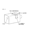
(1-1)図5は、押圧操作部材によってぼけ量変更操作部材51を構成するカメラの例を説明する斜視図である。図5において、カメラ筐体に対して回転可能に構成されるモニタ13の上部にぼけ量変更操作部材51が配設されている。押圧量(操作量)に応じて異なる3種類以上の大きさの操作信号を、ぼけ量を増やすための操作信号として発する操作部材[増]と、押圧量に応じて異なる大きさの操作信号を、ぼけ量を減らすための操作信号として発する操作部材[減]とで一対をなす。ぼけ量変更操作部材51[増]、[減]をズーム操作部材54[T]、[W]と別に配設することで、操作部材を共用する場合と異なり、ズーム操作しながらぼけ量変更操作を行うことが可能である。さらに、押圧操作部材で構成したことにより、回転操作部材に比べて操作時に生じる撮像装置の揺動を抑えることができる。
1. Defocus amount change operation during shooting Since it is assumed that an optical zoom operation is performed during shooting, it is preferable to provide a blur amount change operation member separately from the zoom operation member.
(1-1) FIG. 5 is a perspective view illustrating an example of a camera that constitutes the blur amount changing operation member 51 by a pressing operation member. In FIG. 5, a blur amount changing operation member 51 is disposed on the upper portion of the
(1-2)図6は、図5の例と同様の操作信号を出力する押圧操作部材によってぼけ量変更操作部材51を構成するカメラの他の例を説明する斜視図である。図6において、一対のズーム操作部材54[T]、[W]の近傍に一対のぼけ量変更操作部材51[減]、[増]が配設されている。 (1-2) FIG. 6 is a perspective view for explaining another example of a camera that configures the blur amount changing operation member 51 by a pressing operation member that outputs the same operation signal as in the example of FIG. In FIG. 6, a pair of blur amount changing operation members 51 [decrease] and [increase] are disposed in the vicinity of the pair of zoom operation members 54 [T] and [W].
(1-3)図7は、ジョグダイアル52によってぼけ量変更操作部材およびズーム操作部材を構成するカメラの例を説明する斜視図である。図7において、ジョグダイアル52は、回転操作に応じてズーム操作信号(回転方向がズームアップもしくはズームダウンを示し、回転量がズーム操作量を示す)を発するとともに、押圧量に応じてぼけ量を増減するための操作信号を発する。ジョグダイアル52は、不図示のバネ部材により図7のカメラの背面方向に付勢されており、ジョグダイアル52が押し込まれるとぼけ量を増やすための信号(押圧量によって異なる3種類以上の大きさの操作信号)を発し、ジョグダイアルが引き出されるとぼけ量を減らすための信号を発する。撮影者は、ジョグダイアル52を操作して所望のぼけ量が得られた段階で別に設けられた決定釦を操作して付加するぼけ量を決定する。ズーム操作方向とぼけ量変更操作方向とを異ならせることで、操作部材(ジョグダイアル52)を2系統の操作に共用できる。
(1-3) FIG. 7 is a perspective view for explaining an example of a camera that constitutes the blur amount changing operation member and the zoom operation member by the
(1-4)図8は、仮想絞り環53によってぼけ量変更操作部材を構成するカメラの例を説明する斜視図である。図8において、撮影レンズ2の鏡筒には、撮影レンズ2の光軸に平行な軸を中心に回転可能な仮想絞り環53が配設されている。仮想絞り環53には、回転角を示す指標が仮想絞り値の表示(例えばF1、F2.8等)とともに所定の仮想絞り段数毎(例えば、絞り段数1段毎や1/2段毎)に設けられており、各絞り位置にてクリック感を生じる構造となっている。例えば、仮想絞り環53を仮想絞り値が開放する方向に2段回転させた際には、光学絞りを2段開放させた場合に相当する画像ぼけが付加される。仮想絞り環53が回転操作されると、回転角度(仮想絞り段数)に応じてぼけ量を増減するための操作信号を発するように構成される。筐体の上部に配設される一対のズーム操作部材54[T]、[W]と別に仮想絞り環53を配設することで、右手でズーム操作しながら左手でぼけ量変更操作が可能である。
(1-4) FIG. 8 is a perspective view illustrating an example of a camera that forms a blur amount changing operation member by the virtual diaphragm ring 53. In FIG. 8, a virtual diaphragm ring 53 that is rotatable about an axis parallel to the optical axis of the
(1-5)図9は、図5の例と同様の操作信号を出力する押圧操作部材によってぼけ量変更操作部材51を構成するカメラの例を説明する斜視図である。図9において、カメラ筐体の左側面に一対のぼけ量変更操作部材51[減]、[増]が配設されている。押圧量に応じてそれぞれがぼけ量を増減するための操作信号を発する点は、図5および図6の場合と同様である。カメラ筐体の右上面には、一対のズーム操作部材54[T]、[W]が配設されている。図9の構成によれば、右手でズーム操作を行いながら、左手でぼけ量変更操作を行うことができる。 (1-5) FIG. 9 is a perspective view illustrating an example of a camera that configures the blur amount changing operation member 51 by a pressing operation member that outputs the same operation signal as in the example of FIG. In FIG. 9, a pair of blur amount changing operation members 51 [decrease] and [increase] are arranged on the left side surface of the camera casing. The point that each generates an operation signal for increasing or decreasing the blur amount according to the amount of pressing is the same as in the case of FIGS. A pair of zoom operation members 54 [T] and [W] are disposed on the upper right surface of the camera casing. According to the configuration of FIG. 9, the blur amount changing operation can be performed with the left hand while performing the zoom operation with the right hand.
(1-6)図10は、図9の変形例を示す図である。図9において、カメラ筐体の左側面に一対のぼけ量変更操作部材51[減]、[増]が配設され、カメラの右グリップの上面に、一対のズーム操作部材54[T]、[W]が配設されている。図10の構成でも、右手によるズーム操作と左手によるぼけ量変更操作とを同時に行うことができる。 (1-6) FIG. 10 is a diagram showing a modification of FIG. In FIG. 9, a pair of blur amount changing operation members 51 [decrease] and [increase] are arranged on the left side surface of the camera casing, and a pair of zoom operation members 54 [T] and [ W] is arranged. Even in the configuration of FIG. 10, the zoom operation with the right hand and the blur amount changing operation with the left hand can be performed simultaneously.
(1-7)図11は、図5の例と同様の操作信号を出力するスライド部材である操作ぼけ量変更操作部材51Aおよびズーム操作部材54Aを近傍に配設するカメラの例を説明する図である。ぼけ量変更操作部材51Aは、スライド量(方向)に応じてぼけ量を増減するための操作信号(異なる3種類以上の大きさの操作信号)を発するように構成される。ズーム操作部材54Aは、スライド量(方向)に応じてズームアップ/ズームダウンするための操作信号を発するように構成される。両操作部材を近接させ、操作方向を揃えたことで、異なる指を用いて同時にズーム操作およびぼけ量変更操作を行うことが可能である。上記の図5〜図11の例においては、ぼかし量の大きさを変更する操作部材として操作量に応じて異なる3種類以上の大きさの操作信号を発する操作部材を用いる場合について説明した。このような構成とすれば、画像に対して付加するぼけ量を時間とともに良好に変化させることができ、特に動画像、スルー画像に画像ぼけを付加する場合に好適である。もちろん、これに代えて、操作部材として2値的な出力信号を発する部材を採用し、操作時間に応じて、画像に付加するぼけ量を変更する構成としてもよい。例えば、ズームアップ/ズームダウンを指示する操作部材と、ぼけ量変更操作部材を兼用する構成とすれば、操作部材の数を減らすことができ、装置の小型化が実現できる。例えば、スルー画像、動画像の撮影時には、ズームアップ/ズームダウンを指示する操作部材として機能し、再生モード時にはぼけ量変更操作部材として機能するように構成できる。また、後述する4連スイッチ55を用いる構成としても構わない。この場合の4連スイッチ55は、撮影中はぼけ量変更操作部材として機能し、メニュー選択のための操作部材としては機能しない。 (1-7) FIG. 11 is a diagram for explaining an example of a camera in which an operation blur amount changing operation member 51A and a zoom operation member 54A, which are slide members that output operation signals similar to those in the example of FIG. It is. The blur amount changing operation member 51A is configured to generate an operation signal (an operation signal having three or more different sizes) for increasing or decreasing the blur amount in accordance with the slide amount (direction). The zoom operation member 54A is configured to issue an operation signal for zooming up / down according to the slide amount (direction). By making both operation members close to each other and aligning the operation direction, it is possible to simultaneously perform a zoom operation and a blur amount change operation using different fingers. In the example of FIGS. 5 to 11 described above, the case has been described in which an operation member that generates operation signals of three or more different sizes depending on the operation amount is used as the operation member that changes the amount of blurring. With such a configuration, the amount of blur added to an image can be changed well with time, and is particularly suitable when adding image blur to a moving image and a through image. Of course, instead of this, a member that emits a binary output signal may be employed as the operation member, and the amount of blur added to the image may be changed according to the operation time. For example, if the operation member for instructing zoom-up / zoom-down is combined with the blur amount changing operation member, the number of operation members can be reduced and the apparatus can be downsized. For example, it can be configured to function as an operation member for instructing zoom-up / zoom-down when shooting a through image or a moving image, and to function as a blur amount changing operation member in the playback mode. Further, a configuration using a quadruple switch 55 described later may be used. The quadruple switch 55 in this case functions as a blur amount changing operation member during shooting, and does not function as an operation member for menu selection.
2.再生時のぼけ量変更操作
再生時(電気的な画像ぼけの付加が許可された状態で、記録された画像を再生する場合)はぼけ量変更操作と電子ズーム操作とが可能に構成され、光学的なズーム操作は行われない。制御回路5は、記録媒体12に記録されている画像データを読み出し、読み出しデータに対して復号化処理を施し、復号化後のデータをデータ処理回路10へ送る。制御回路5は、復号化後のデータから主要被写体の抽出処理を行い(ステップS103と同様)、抽出した主要被写体以外の領域(すなわち背景領域)に対する画像ぼけの付加処理をデータ処理回路10へ指示する(ステップS104と同様)。制御回路105はさらに、ぼけ量変更操作が行われるとぼけ量を変更させる(ステップS109、S110と同様)。
2. Blur amount change operation during playback During playback (when recorded images are played back with the addition of electrical image blur enabled), it is possible to change the blur amount and perform electronic zoom operations. Zoom operation is not performed. The control circuit 5 reads the image data recorded on the
(2-1)図5および図6、図9〜図11に例示したカメラの再生時には、ぼけ量変更操作部材51(図11の場合は51A)[増]、[減]が押圧操作されると、それぞれがぼけ量を増減するための操作信号を発するように構成される。 (2-1) When the camera illustrated in FIGS. 5 and 6 and FIGS. 9 to 11 is played back, the blur amount changing operation member 51 (51A in FIG. 11) [increase] and [decrease] is pressed. And an operation signal for increasing or decreasing the amount of blur.
(2-2)図7に例示したカメラの再生時には、ジョグダイアル52の回転操作によってぼけ量を増減するための操作信号を発するように構成される。すなわち、回転方向がぼけ量の増減に対応し、回転量が増減量に対応するように、ぼけ量を変化させるためのジョグダイアル52の操作が撮影時と異なり、ジョグダイアル52によって再生時に変更される機能が限定される。
(2-2) At the time of reproduction of the camera illustrated in FIG. 7, an operation signal for increasing or decreasing the amount of blur is generated by rotating the
(2-3)図5〜図7に例示したカメラの場合、メニュー選択のための操作部材として配設されている4連スイッチ(SW)55を再生時のぼけ量変更操作部材としてもよい。 (2-3) In the case of the camera illustrated in FIGS. 5 to 7, a quadruple switch (SW) 55 provided as an operation member for menu selection may be used as a blur amount changing operation member during reproduction.
(2-4)図8に例示したカメラの再生時に、仮想絞り環53の操作に基づいて、再生画像に付加される画像ぼけの量を変更する構成としてもよい。この場合、仮想絞り環53は、実際に光学絞りの絞り値を変更する操作部材であっても構わない。この操作部材から出力される操作信号は制御回路5に入力され、制御回路5の制御のもとで、再生画像に対する画像ぼけの付加量が変更される。この操作部材の操作によって、光学絞りが駆動され光学絞り値が変更されたとしても、再生画像に対して何ら影響を及ぼすものではないことは言うまでもない。消費電力の観点から、再生モード時にこの操作部材が操作された場合には、光学絞りを駆動することなく、再生画像に対する画像ぼけの付加量を変更することが好ましい。 (2-4) At the time of playback of the camera illustrated in FIG. 8, the amount of image blur added to the playback image may be changed based on the operation of the virtual aperture ring 53. In this case, the virtual aperture ring 53 may be an operation member that actually changes the aperture value of the optical aperture. An operation signal output from the operation member is input to the control circuit 5, and under the control of the control circuit 5, the amount of image blur added to the reproduced image is changed. It goes without saying that even if the optical aperture is driven and the optical aperture value is changed by the operation of the operating member, the reproduced image is not affected at all. From the viewpoint of power consumption, when this operating member is operated in the playback mode, it is preferable to change the amount of image blur added to the playback image without driving the optical aperture.
(2-5)また、スルー画撮影時には画像ぼけの付加を行わず、本撮影された静止画像を記録媒体12に記録する前、もしくは記録した後に、モニタ13に表示した上で画像ぼけを付加するような場合には、ズーム操作と画像ぼけの付加、変更操作は必ずしも同時に行う必要はない。従って、図5から図11のぼけ量を変更する操作部材51,52,53,51Aは必ずしも必要ではなく、ズーム操作部材54のような他の用途に用いられる操作部材で兼用することができる。例えば、本撮影された静止画像がモニタ13に表示されている状態でズーム操作部材54のスイッチ[T]を押圧すると、操作時間に応じて画像ぼけの量が大きくなり、スイッチ[W]を押圧すると、操作時間に応じて画像ぼけの量が小さくなる。また、スイッチ[T]とスイッチ[W]を同時に押圧操作すると、モニタ13上で付加された画像ぼけをリセット(画像ぼけが付加されていない状態にする)ことができる。このような操作は、4連スイッチ55によって行ってもよい。付加する画像ぼけの量を4連スイッチ55を用いて変更する構成とすれば、ズーム操作部材54等の操作により、モニタ13上の像を電気的に拡大することができ、画像ぼけを付加しつつ、細部にわたって画像確認を行うことができる。
(2-5) In addition, image blur is not added at the time of through image shooting, and the still image that is actually shot is recorded on the
上記のようなぼけ量変更操作に伴い、仮想絞り値を画像とともにモニタ13に重畳表示するように構成してもよい。仮想絞り値は、付加される画像ぼけ量と等価な光学ぼけを与える光学絞り値とする。仮想絞り値は、例えば、画像ぼけの付加量を決めるLPF特性(あるいは点拡がり関数)を示すデータの関数として算出してもよいし、画像ぼけの付加量を引数としてルックアップテーブルから読み出せるようにあらかじめテーブル化しておいてもよい。このように算出した仮想絞り値が表示されることにより、撮影者は、付加される画像ぼけの量を直感的に把握することができる。
Along with the blur amount changing operation as described above, the virtual aperture value may be superimposed and displayed on the
仮想絞り値をモニタ13に表示する場合、モニタ13に実際の撮影レンズ2の光学絞り値を表示しているときは、光学絞り値と仮想絞り値とを異なる態様(例えば異なる表示色)で表示するとより一層好適である。異なる態様で表示することで、撮影者が両者を識別し易くなる。
When displaying the virtual aperture value on the
トリミング等の画像編集作業などのために、再生モード時に電子ズーム操作が行われると、モニタ13の表示画面には再生画像の一部が表示される。この場合、撮影時に合焦した主要被写体が表示中の電子ズーム範囲に含まれないことがある。この場合には、モニタ13の表示範囲に対応する画像信号についての高周波数成分の積算値(いわゆる焦点評価値)を最大にする領域を抽出し、この領域をズーム画面における主要被写体とみなす。焦点評価値の最大値を含む領域は、表示中の電子ズーム画面の中で最もピントが合っている(画像の尖鋭度が高い)と思われる領域である。このような構成とすれば、モニタ13が拡大表示しようとする範囲に、撮影の際の自動合焦動作における焦点検出領域が含まれていない場合であっても、画像ぼけを付加しない領域を適切に判断することができる。モニタ13が拡大表示しようとする範囲に、自動合焦動作に用いられた焦点検出領域がある場合には、この領域を基準に、この領域以外の領域に画像ぼけを付加する構成としてもよい。この場合には、上述の高周波数成分の積算値の算出処理は行わない。制御回路5は、この抽出領域を基準に、抽出した領域以外の領域(すなわち背景領域)に対する画像ぼけの付加処理をデータ処理回路10へ指示する(ステップS104と同様)。制御回路5はさらに、ぼけ量変更操作が行われるとぼけ量を変更させる(ステップS109、S110と同様)。
When an electronic zoom operation is performed in the playback mode for image editing work such as trimming, a part of the playback image is displayed on the display screen of the
なお、モニタ13の表示範囲に対応する画像信号から焦点評価値の最大値を含む領域が抽出不能の場合や、電子ズーム画面の中央を基準にするように指示されている場合には、表示中の電子ズーム画面の中央部をピントが合っている領域とみなす。制御回路5は、この中央部を基準に、中央部以外の領域に対する画像ぼけの付加処理をデータ処理回路10へ指示する。このような構成とすれば、注目する被写体が存在する可能性が高い画面の中央部を除いた領域に画像ぼけが付加されるので、誤った場所に画像ぼけが付加されてしまう可能性が低減する。
If the region including the maximum focus evaluation value cannot be extracted from the image signal corresponding to the display range of the
以上説明した第一の実施形態によれば、以下の作用効果が得られる。
(1)撮像装置(画像再生装置、画像処理装置)は、画像信号の高周波数成分の積算値を演算して画像の尖鋭度が高い領域を検出し、当該画像信号のうち、検出領域と異なる領域に対応する信号に画像ぼけを付加するようにしたので、画像ぼけを付加すべき領域(ピントが合っている領域と異なる背景領域)を適切に抽出し、ぼかしを付加することができる。
According to the first embodiment described above, the following operational effects can be obtained.
(1) An imaging device (an image reproduction device or an image processing device) calculates an integrated value of high-frequency components of an image signal to detect a region where the sharpness of the image is high, and is different from the detection region in the image signal. Since the image blur is added to the signal corresponding to the area, it is possible to appropriately extract the area where the image blur should be added (the background area different from the in-focus area) and add the blur.
(2)上記(1)の撮像装置(画像再生装置)は、電子ズーム倍率を高める方向に解像度変換を行って再生画像の一部をモニタ13に拡大表示する場合、モニタ13の表示範囲に対応する画像信号から画像の尖鋭度が高い領域を検出するようにしたので、表示範囲の中で画像ぼけを付加すべき領域(ピントが合っている領域と異なる背景領域)を適切に抽出し、ぼかしを付加することができる。上記の電子ズーム動作は、連続的に行われるものに限定されず、トリミングしての拡大動作など1回しか行われない場合も含む。
(2) The imaging device (image reproduction device) of (1) above corresponds to the display range of the
(3)上記(1)の撮像装置(画像再生装置)は、電子ズーム倍率を高める方向に解像度変換を行って再生画像の一部をモニタ13に拡大表示する場合、モニタ13の表示範囲の中央部に対応する領域を検出するようにしたので、表示範囲の中にピントが合っている領域がない場合に、表示範囲中央部にぼかしを付加することができる。
(3) When the imaging device (image reproduction device) of (1) performs resolution conversion in the direction of increasing the electronic zoom magnification and enlarges and displays a part of the reproduction image on the
(4)解像度変換比率(電子ズーム倍率)に応じて付加する画像ぼけの大きさを変更するようにすれば、従来の光学的なズーム動作において付加される光学的なぼけと同様の動作を実現できる。特に、光学的なズーム動作に継続して電子ズーム動作が行われる場合であっても違和感のない画像を得ることができる。 (4) If the size of the image blur to be added is changed according to the resolution conversion ratio (electronic zoom magnification), the same operation as the optical blur added in the conventional optical zoom operation is realized. it can. In particular, even when the electronic zoom operation is performed following the optical zoom operation, an image without a sense of incongruity can be obtained.
(5)画像ぼけの付加と解像度変換(電子ズーム)との双方を行う場合で、少なくとも電子ズーム倍率を高める方向に解像度変換を行う場合は、解像度変換後に画像ぼけを付加する構成とする。これにより、画質劣化が抑えられ、解像度変換前に画像ぼけを付加する構成に比べて、電子ズームの最大拡大倍率を高く設定できる。 (5) When both image blur addition and resolution conversion (electronic zoom) are performed and resolution conversion is performed at least in the direction of increasing the electronic zoom magnification, the image blur is added after resolution conversion. As a result, image quality deterioration can be suppressed, and the maximum enlargement magnification of the electronic zoom can be set higher than in a configuration in which image blur is added before resolution conversion.
(6)ダイアル部材である操作ぼけ量変更操作部材53からぼけ量を増減するための操作信号を発するように構成したので、従来の操作性を維持した簡単な操作でぼかしの大きさを変更できる。 (6) Since the operation signal for increasing / decreasing the blur amount is issued from the operation blur amount changing operation member 53 which is a dial member, the size of the blur can be changed by a simple operation maintaining the conventional operability. .
(7)仮想絞り値(付加される画像ぼけ量と等価な光学ぼけを与える光学絞り値)を画像とともにモニタ13に重畳表示するようにすれば、撮影者は、付加される画像ぼけの量を直感的に把握することができる。この際に電子ズーム倍率に応じた仮想的な焦点距離も表示する構成とすれば、より一層好適である。
(7) If a virtual aperture value (an optical aperture value that gives an optical blur equivalent to the amount of image blur to be added) is superimposed on the
(変形例1)
ぼけ量変更操作部材の操作に応じて画像ぼけの付加量を変更する他に、被写体と撮像装置との間の距離(撮影距離)情報に応じて、デフォルト状態で設定されている画像ぼけ量を変更する構成としてもよい。距離情報は、AF動作中に取得されている距離情報を用いる。制御回路5は、移動する被写体と撮像装置との間の撮影距離がある時点より短くなると、移動被写体と静止している背景との間の距離が広がったとみなす。移動被写体を対象にAF動作を行う場合、移動被写体に合焦させる動作が連続的に行われるため、移動被写体についての焦点調節状態は変化しない。この場合の制御回路5は、背景領域に対して付加するぼけ量を、上記ある時点と比較して大きくするように制御する。
(Modification 1)
In addition to changing the added amount of image blur according to the operation of the blur amount changing operation member, the image blur amount set in the default state is set according to the distance (shooting distance) information between the subject and the imaging device. It is good also as a structure to change. As the distance information, distance information acquired during the AF operation is used. The control circuit 5 considers that the distance between the moving subject and the stationary background has increased when the shooting distance between the moving subject and the imaging apparatus becomes shorter than a certain point. When performing an AF operation on a moving subject, the focus adjustment state for the moving subject does not change because the operation of focusing on the moving subject is continuously performed. In this case, the control circuit 5 performs control so that the amount of blur added to the background area is increased compared to the certain time point.
反対に、移動する被写体との撮像装置との間の撮影距離がある時点より長くなると、制御回路5は、移動被写体と静止している背景との間の距離が縮まったとみなす。制御回路5は、背景領域に対して付加するぼけ量を、上記ある時点と比較して小さくするように制御する。 On the other hand, when the shooting distance between the moving subject and the imaging device becomes longer than a certain point, the control circuit 5 considers that the distance between the moving subject and the stationary background is reduced. The control circuit 5 controls the amount of blur added to the background area to be smaller than the certain time point.
変形例1では、移動被写体および背景間の距離に応じて画像ぼけ量を変更する例を説明したが、複数の移動被写体に対してそれぞれ距離情報を取得し、複数の移動被写体間の距離に応じて各被写体領域に付加するぼけ量を動的に変化させてもよい。複数の移動被写体に対する距離情報は、例えば、複数のフォーカス検出領域ごとに当該領域に存在する被写体までの距離情報を取得すればよい。 In the first modification, the example in which the image blur amount is changed according to the distance between the moving subject and the background has been described. However, distance information is acquired for each of the plurality of moving subjects, and the distance between the plurality of moving subjects is determined. The amount of blur added to each subject area may be dynamically changed. As the distance information for a plurality of moving subjects, for example, distance information to a subject existing in each of the plurality of focus detection regions may be acquired.
(変形例2)
以上の説明では、画像ぼけを付加した後に半押し操作が解除されると(ステップS111を否定判定)、画像ぼけの付加を解除するようにしたが、撮影レンズ2の光学絞りが変更された場合にも画像ぼけの付加を解除する構成にしてもよい。光学絞りは、例えば不図示の絞り環や操作部材7からの操作信号によって変更される。制御回路5は、このような光学絞りの変更指示に応じて、現時点において付加している画像ぼけを一旦解除する。この結果、光学的なぼけと電気的に付加する画像ぼけとの双方を迅速に設定し直すことが可能になる。
(Modification 2)
In the above description, when the half-press operation is canceled after adding the image blur (determination is negative in step S111), the addition of the image blur is canceled, but the optical aperture of the taking
(変形例3)
ステップS105の説明では、フレーム間の動きベクトルを検出することによって撮影画面に動きがあるか否かを判定するようにした。この代わりに、角速度センサ、角加速度センサ、および加速度センサなどのいずれかの動きセンサを撮像装置に配設し、センサによる検出結果を用いて判定する構成にしてもよい。
(Modification 3)
In the description of step S105, it is determined whether or not there is a motion on the shooting screen by detecting a motion vector between frames. Instead, any one of motion sensors such as an angular velocity sensor, an angular acceleration sensor, and an acceleration sensor may be provided in the imaging apparatus, and a determination may be made using a detection result of the sensor.
(変形例4)
上述したように、ステップS105およびステップS107の判定をともに動きベクトルを用いて行う場合には、ステップS105の判定処理と、ステップS107の判定処理とを並行して行ってもよい。
(Modification 4)
As described above, when both the determinations in step S105 and step S107 are performed using motion vectors, the determination process in step S105 and the determination process in step S107 may be performed in parallel.
(変形例5)
画像ぼけを付加することなしにスルー画像をモニタ13に表示するように設定され、本撮影で得られる本撮影画像に対してのみ画像ぼけを付加する設定が行われている撮像装置の場合、上記ステップS113で説明した内容に代えて次のように本撮影用の露出を決定するとよい。すなわち、画像ぼけが付加されていない直近のスルー画像データの信号値(明るさ情報)に基づいて本撮影用の露出を演算し、この演算値を本撮影画像に付加される画像ぼけの量に応じて補正し、補正後の演算値に基づいて本撮影用の露出を決定する。撮像装置は、決定された露出に基づいて、撮像素子1の電子シャッタ速度(電荷蓄積時間)、絞り、撮像素子1の出力する画像信号の増幅度等を設定し、撮像動作を行う。これにより、例えば、スポット測光領域に輝点が含まれており、この輝点に画像ぼけを付加すると画像ぼけ領域が測光領域より大きくなってしまう場合のように、画像ぼけが付加されることによって画像の明るさの判定が変化する場合でも、適切な明るさの本撮影画像が得られる。
(Modification 5)
In the case of an imaging apparatus that is set to display a through image on the
(変形例6)
画像ぼけの付加(および付加内容の変更)の許可/禁止を判定する処理において、例えば、夜景ポートレートモードであっても画像の背景領域に所定レベル以上の明るさを有する領域が存在しない場合に、画像ぼけの付加(および付加内容の変更)を禁止する例を説明したが、次のようにしてもよい。すなわち、スルー画像もしくは本撮影画像をモニタ13に表示する場合には画像ぼけの付加を禁止することをデフォルト設定とし、操作部材7から画像ぼけの付加を指示する操作信号が制御回路5へ入力された場合にのみ、画像ぼけの付加を許可する。もちろん、画像ぼけの付加が許可された状態では、画像ぼけを付加したデータを記録媒体12へ記録可能に構成される。
(Modification 6)
In the process of determining permission / prohibition of image blur addition (and change of the added content), for example, when there is no area having a brightness of a predetermined level or more in the background area of the image even in the night view portrait mode. The example of prohibiting the addition of image blur (and the change of the added content) has been described, but it may be as follows. In other words, when displaying a through image or an actual captured image on the
(変形例7)
ポートレートモードなどの撮影モードの設定状態に応じて画像ぼけの付加(および付加内容の変更)の許可/禁止を判定する処理に代えて、スルー画像中に人の顔が認識されるか否かに応じて画像ぼけの付加(および付加内容の変更)の許可/禁止を判定してもよい。この場合の制御回路5は、上述したAF動作の終了後に撮像される画像であって、画像ぼけが付加されていないスルー画像を用いて公知の顔認識処理を施し、顔領域を抽出する。制御回路5は、抽出した顔領域を含む被写体を主要被写体とする。人の顔が認識された画像だけ、制御回路5によって画像ぼけの付加を許容する構成としてもよい。このような構成とすれば、人の顔が認識された場合に自動的にポートレート調の撮影を行うことができる。さらに、人の顔の数(例えば2人以下)、大きさ(所定値以上)の条件を満足したときに画像ぼけを付加するように構成してもよい。
(Modification 7)
Whether or not a human face is recognized in the through image, instead of the process for determining whether to allow or prohibit the addition of image blur (and change of the added content) according to the setting state of the shooting mode such as the portrait mode The permission / prohibition of the addition of image blur (and the change of the added content) may be determined according to. In this case, the control circuit 5 performs a known face recognition process using a through image that is captured after the above-described AF operation and has no image blur, and extracts a face area. The control circuit 5 sets the subject including the extracted face area as the main subject. Only the image in which the human face is recognized may be configured to allow image blurring by the control circuit 5. With such a configuration, it is possible to automatically perform portrait photography when a human face is recognized. Further, the image blur may be added when the conditions of the number of human faces (for example, two or less) and the size (a predetermined value or more) are satisfied.
なお、画像ぼけの付加(および付加内容の変更)を本撮影画像にのみ行うように設定されている(スルー画像には付加しない)場合にも、画像ぼけが付加されていないスルー画像を用いて顔認識処理を施し、顔領域が認識された場合に本撮影画像に対する画像ぼけの付加(および付加内容の変更)を許可するように構成してもよい。このような構成とすれば、被写体認識処理を正確かつ迅速に行える。 Note that even when it is set to add image blur (and change of the added content) only to the actual captured image (not added to the through image), the through image without the image blur is used. It may be configured to perform face recognition processing and permit addition of image blur (and change of the added content) to the actual captured image when a face area is recognized. With such a configuration, subject recognition processing can be performed accurately and quickly.
(変形例8)
画像ぼけの付加が許可された場合に絞り優先オートモードに設定する(ステップS102)代わりに、撮影レンズ2の光学絞りを所定の絞り値(例えば、開放値)に設定する構成にしてもよい。光学絞りに起因する光学ぼけが所定の状態に維持されるので、被写体輝度の変動にともなって本画像のぼけ量(光学ぼけと付加された画像ぼけの総和)が変動することが防止される。これにより、画像ぼけの付加量の設定変更操作が容易になる。なお、光学絞りを所定の絞り値に設定することにより、設定前後でモニタ13に表示されるスルー画像の明るさが変化しないように、光学絞りの変更段数に応じてリアルタイムに撮像素子1の電荷蓄積時間(もしくは撮像素子1より出力される信号の増幅率)を異ならせるとよい。
(Modification 8)
Instead of setting the aperture priority auto mode when addition of image blur is permitted (step S102), the optical aperture of the taking
上記所定の絞り値を開放値に固定する場合には、被写界深度が浅くなり、画像ぼけを付加する領域の確認や指定操作が容易になる。 When the predetermined aperture value is fixed to the open value, the depth of field becomes shallow, and the confirmation and designation operation of the area to which the image blur is added becomes easy.
(変形例9)
スルー画像から抽出した主要被写体の背景の領域に対して画像ぼけの付加を行うようにしたが、操作部材7の操作信号(例えば、カーソル位置を示す信号)によって示される領域に画像ぼけの付加を行うように構成してもよい。カーソルで示される被写体に画像ぼけが付加され、主要被写体を引き立たせる撮影効果が得られる。
(Modification 9)
Although the image blur is added to the background area of the main subject extracted from the through image, the image blur is added to the area indicated by the operation signal of the operation member 7 (for example, a signal indicating the cursor position). It may be configured to do. An image blur is added to the subject indicated by the cursor, and a shooting effect that enhances the main subject is obtained.
(変形例10)
以上の説明では、レリーズ釦が半押し操作されると(ステップS101を肯定判定)、モニタ13に表示される画像に画像ぼけを付加するようにしたが、操作部材7(例えば、ビュースイッチ)が操作されたときに画像ぼけを付加した画像をモニタ13表示するように構成してもよい。ビュースイッチの操作に応じて画像ぼけが付加された画像をモニタ13へ表示する場合、ビュースイッチからの操作信号が継続している間は同一の撮像画面(スルー画像)を連続して表示すると好適である。撮影者は、表示画面(フリーズ画面)をゆっくり確認することができる。また、これにより、撮影者が画像ぼけを確認したいときのみ、画像ぼけが付加されるので信号処理の負担が少ない。また、従来の一眼レフカメラと同様の使い勝手を実現することができる。
(Modification 10)
In the above description, when the release button is pressed halfway (Yes in step S101), image blur is added to the image displayed on the
なお、モニタ13の表示がオフされている場合には、ビュースイッチからの操作信号を無効にする。この場合には、画像ぼけの付加(および付加内容の変更)を本撮影画像にのみ行うように設定されている場合と同様に、スルー画像に対する画像ぼけの付加を省略する。
When the display on the
(変形例11)
変形例10と反対に、モニタ13の表示がオフされている状態でビュースイッチからの操作信号が入力される場合に、モニタ13をオン(起動)させてもよい。この場合には、ビュースイッチの操作に応じてモニタ13を起動し、画像ぼけが付加された画像をモニタ13へ表示する。ビュースイッチからの操作信号が継続している間は同一のスルー画像を静止画像として表示すると好適である。
(Modification 11)
Contrary to the
(変形例12)
撮影時の撮影モードがポートレートモード、およびマクロモードに設定されている場合に画像ぼけの付加(および付加内容の変更)を許可する例を説明したが、次のように構成してもよい。すなわち、ポートレートモード、およびマクロモードに設定されている場合の操作メニューモードに「画像ぼけ」に関するメニュー項目を含め、このメニュー項目において「画像ぼけ」を「付加する」ように指示された場合に画像ぼけの付加(および付加内容の変更)を許可する。一方、撮影モードがポートレートモード、およびマクロモードであっても、メニュー項目において「画像ぼけ」を「付加しない」ように指示された場合には画像ぼけの付加(および付加内容の変更)を禁止する。ポートレートモードやマクロモードでも、画像ぼけを付加するか否かを自分で決めたいという撮影者の希望をかなえる撮像装置が得られる。一方、画像ぼけの付加を許可する/許可しないの設定が、撮影モードの設定より上位にあって(優先して設定されて)、ポートレートモード、マクロモード以外の撮影モードであっても、画像ぼけの付加を許可する設定となっているときには、画像ぼけの付加を許容する構成としてもよい。
(Modification 12)
Although an example in which addition of image blur (and change of addition contents) is permitted when the shooting mode at the time of shooting is set to portrait mode and macro mode has been described, the following configuration may be used. That is, when the operation menu mode when the portrait mode and the macro mode are set includes a menu item related to “image blur”, and the menu item is instructed to “add” “image blur”. Allows adding image blur (and changing the added content). On the other hand, even if the shooting mode is portrait mode or macro mode, if the menu item is instructed not to add “image blur”, it is prohibited to add image blur (and change the added content). To do. Even in the portrait mode or the macro mode, an imaging apparatus that can fulfill the photographer's desire to decide whether or not to add image blur can be obtained. On the other hand, even if the setting to allow / do not allow image blur is higher than the shooting mode setting (prioritized setting) and the shooting mode is not portrait mode or macro mode, If the setting is to permit the addition of blur, the configuration may be made to allow the addition of image blur.
(変形例13)
付加する画像ぼけの量を変更する際、ぼけ量変更操作部材の押圧量(もしくは回転量)に応じて付加する画像ぼけ量を変更(決定)するようにしたが、ぼけ量変更操作部材からの操作信号によって示される仮想絞り値に応じて付加する画像ぼけ量を変更する構成にしてもよい。この場合の制御回路5は、ぼけ量変更操作部材からの操作信号に応じた仮想絞り値を画像とともにモニタ13に重畳表示させるとともに、この仮想絞り値に対応する画像ぼけを付加するようにデータ処理回路10へ指示を送る。仮想絞り値は、現時点の画像に付加する画像ぼけ量と等価な光学ぼけを与える光学絞り値とする。ぼけ量変更操作を仮想絞り値(例えばF11→F5.6)の変更操作として行う構成にすることで、撮影者は、現時点の画像に対して付加される画像ぼけの量を直感的に把握することができる。
(Modification 13)
When changing the amount of image blur to be added, the image blur amount to be added is changed (determined) according to the pressing amount (or rotation amount) of the blur amount changing operation member. The image blur amount to be added may be changed according to the virtual aperture value indicated by the operation signal. In this case, the control circuit 5 superimposes the virtual aperture value corresponding to the operation signal from the blur amount changing operation member on the
(変形例14)
付加する画像ぼけの量を変更する際、ぼけ量変更操作部材からの操作信号によって示される仮想絞り段数に応じて付加する画像ぼけ量を変更(決定)する構成にしてもよい。この場合の制御回路5は、ぼけ量変更操作部材からの操作信号に応じた仮想絞り段数を画像とともにモニタ13に重畳表示させるとともに、この仮想絞り段数に対応する画像ぼけを付加するようにデータ処理回路10へ指示を送る。仮想絞り段数は、現時点の画像に付加する画像ぼけ量と等価な光学ぼけを与える光学絞り段数とする。ぼけ量変更操作を仮想絞り段数(例えば−2段)の変更操作として行う構成にすることで、撮影者は、現時点の画像に対して付加される画像ぼけの量を直感的に把握することができる。
(Modification 14)
When changing the amount of image blur to be added, the image blur amount to be added may be changed (determined) according to the number of virtual aperture stages indicated by the operation signal from the blur amount changing operation member. In this case, the control circuit 5 superimposes the virtual diaphragm step number corresponding to the operation signal from the blur amount changing operation member on the
(変形例15)
画像ぼけの付加と電子ズーム動作の双方を行う場合において、画質劣化を抑えるために電子ズーム後に画像ぼけを付加する点と、付加する画像ぼけの程度(量)が大きいほど電子ズームの最大拡大倍率を高く設定する点とを説明したが、電子ズーム倍率に応じて付加する画像ぼけの程度(量)を変更するように構成してもよい。電子ズーム倍率が小さい場合は、画像ぼけの付加量を小さく抑える。通常、撮影レンズ2の焦点距離が長くなるほど(拡大倍率が大きくなるほど)光学的なぼけの量は大きい。上記の構成によれば、電子的なズーム動作によっても、この動作と同様の画像を得ることができる。
(Modification 15)
In both cases of adding image blur and electronic zoom operation, the point to add image blur after electronic zoom to suppress image quality degradation, and the maximum enlargement magnification of electronic zoom as the degree (amount) of added image blur increases However, the degree (amount) of image blur to be added may be changed according to the electronic zoom magnification. When the electronic zoom magnification is small, the amount of added image blur is kept small. Usually, the longer the focal length of the taking lens 2 (the larger the magnification), the greater the amount of optical blur. According to said structure, the image similar to this operation | movement can be obtained also by electronic zoom operation | movement.
反対に、電子ズーム倍率が大きい場合は画像ぼけ付加量を大きくするが、電子ズーム前の画像に対する電子ズーム処理による拡大倍率が所定倍(例えば3倍)以上の場合は画像ぼけの付加を省略する(付加量を0にする)。これにより、高い電子ズーム倍率で画質劣化が進んだ画像に対し、無駄な画像ぼけの付加を止めることができる。このような構成は、画像ぼけを付加した後に電子ズーム処理を行う装置に対しても同様に適用することができる。 Conversely, when the electronic zoom magnification is large, the image blur addition amount is increased. However, when the enlargement magnification by the electronic zoom processing on the image before the electronic zoom is a predetermined magnification (for example, 3 times) or more, the addition of image blur is omitted. (Addition amount is set to 0). Thereby, it is possible to stop adding unnecessary image blur to an image whose image quality has deteriorated at a high electronic zoom magnification. Such a configuration can be similarly applied to an apparatus that performs electronic zoom processing after adding image blur.
(変形例16)
本撮影時の露出条件を段階的に変化させ、それぞれの露出値で複数の画像データを得るAEブラケティング撮影を行うように撮像装置が設定されている場合に、撮影レンズ2の絞り値を変えて露出条件を変化させることにより、複数の画像データを得るように構成してもよい。この場合の制御回路5は、複数の画像間で本撮影静止画像のぼけ量(光学ぼけと付加された画像ぼけの総和)が略一定になるように、各画像に付加する画像ぼけ量を段階的に異ならせる。これにより、光学絞り値を変更して通常のAEブラケティングを行うと各画像間で明るさおよび被写体深度(ぼけの状態)が異なるが、変形例16では、各画像間で明るさのみが異なって被写体深度が同等の画像を得ることができる。
(Modification 16)
When the imaging apparatus is set to perform AE bracketing shooting that obtains a plurality of image data at each exposure value by gradually changing the exposure conditions during actual shooting, the aperture value of the
(変形例17)
本撮影時の画像ぼけの付加量を段階的に変化させ、それぞれの付加量で複数の画像データを得る画像ぼけブラケティング撮影を行うように構成してもよい。制御回路5は、複数の画像間で画像ぼけの付加量を段階的に異ならせる。これにより、本撮影時の露出条件を変化させなくても、各画像間で被写体深度が異なる画像を得ることができる。
(Modification 17)
It may be configured to perform an image blur bracketing shooting in which a plurality of image data is obtained with each additional amount by changing the additional amount of image blur at the time of main photographing stepwise. The control circuit 5 varies the added amount of image blur step by step between a plurality of images. Thereby, it is possible to obtain images having different subject depths between the respective images without changing the exposure conditions during the main photographing.
(変形例18)
画像ぼけの付加が許可された場合に絞り優先オートモードに設定したり(ステップS102)、撮影レンズ2の光学絞りを所定値に設定したり(変形例8)する代わりに、撮像装置が決定した制御絞り値に応じて、付加する画像ぼけの大きさを決定する構成にしてもよい。この場合の撮像装置は、露出モードがプログラムオートモードまたはシャッタ速度優先オートモードに設定されている。プログラムオートモードは、明るさ情報に応じて制御絞り値および制御シャッタ秒時(電荷蓄積時間)の組み合わせを決定する露出モードである。この際に、さらに画像信号の増幅度を変更するものであってもよい。制御絞り値および制御シャッタ秒時(電荷蓄積時間)等の組み合わせは、プログラム線図データとしてあらかじめ制御回路5内に記憶されている。シャッタ速度優先オートモードは、設定されているシャッター秒時(電荷蓄積時間)で適正露出が得られるように、明るさ情報に応じて制御絞り値等を決定する露出モードである。
(Modification 18)
Instead of setting the aperture priority auto mode when image blur addition is permitted (step S102) or setting the optical aperture of the
露出モードがプログラムオートモード、またはシャッタ速度優先オートモードの場合、撮影時の撮影レンズ2の光学絞り値は制御絞り値に制御されるので、検出される被写体の明るさ情報によって、光学絞り値に起因する光学ぼけの大きさが異なる。具体的には、制御絞り値が開放値に近づくと光学ぼけが大きくなり、制御絞り値が絞り込まれると光学ぼけが小さくなる。そこで、このような光学ぼけの大きさの変動をキャンセルするように、制御絞り値に応じて付加する画像ぼけの大きさを決定する構成にすれば、本画像のぼけ量(光学ぼけと付加された画像ぼけの総和)を一定に保つことができる。
When the exposure mode is the program auto mode or the shutter speed priority auto mode, the optical aperture value of the taking
<モニタ表示の変形例1>
画像をモニタ13へ表示する場合の他の表示態様について、図4(c)を参照して説明する。図4(c)によれば、画像ぼけが付加された領域/付加されない領域を撮影者が容易に視認できるように、画像ぼけを付加しない領域(この場合は主要被写体300の領域)を他の領域に比べて明るく表示する。図4(c)では、主要な各被写体の輪郭の線の太さを変えることによって明るさの違いを表しており、線が太いほど輝度を高めて明るく表示される。つまり、主要被写体300を一番明るく表示し、被写体301、被写体302の順に、画像ぼけの付加量(ぼけ効果の大きさ)が多いほどその被写体を暗く表示する。このように被写体の明るさを変えて表示することにより、撮影者は、画像ぼけが付加された領域/付加されない領域を容易に視認できるとともに、表示の明るさから付加された画像ぼけ量を直感的に把握できる。なお、画像ぼけの付加量が多いほど、その被写体を明るく表示する構成にしてもよい。
<Modified example 1 of monitor display>
Another display mode for displaying an image on the
<モニタ表示の変形例2>
画像ぼけが付加された画像をモニタ13へ表示する場合、着色によって画像ぼけの付加量の違いを表してもよい。この場合の制御回路5は、通常、モノクロ画像をモニタ13に表示させ、画像ぼけを付加した画像を表示する場合には、画像ぼけを付加した領域に色をつけて表示させる。この際、画像ぼけの付加量(ぼけ効果の大きさ)が多いほど、その被写体を色濃く表示させる。このように被写体の色の濃淡を変えて表示することにより、撮影者は、画像ぼけが付加された領域/付加されない領域を容易に視認できるとともに、色の濃淡から付加された画像ぼけ量を直感的に把握できる。
<Modified example 2 of monitor display>
When an image with added image blur is displayed on the
<モニタ表示の変形例3>
また、画像ぼけが付加された領域について撮影者の視認性の向上を図るために、モニタ13による表示画像において画像ぼけの付加量を実際より大きくした上で表示させてもよい。また、撮像装置の小型化によってモニタ13の大きさが制限される場合には、小さな画面からでも撮影者が容易に視認できるように画像ぼけの付加領域を広げ、強調して表示させてもよい。モニタ13の画面が小さかったり、モニタ13の表示画素数が少ない場合に画像ぼけの付加量、付加領域を強調表示することで、画像ぼけが付加された領域/付加されない領域を撮影者にわかりやすく表示することができる。
<Modified example 3 of monitor display>
In addition, in order to improve the photographer's visibility in the region where the image blur is added, the display image on the
以上説明したモニタ表示の変形例1〜3による表示態様は、操作部材7からの操作信号に応じて通常の表示態様(第一の実施形態で説明した表示態様)との間で切り替え可能に構成してもよい。例えば、強調表示スイッチ(不図示)が操作されている間にのみ上記態様で表示する構成とすれば、撮影者が必要とする場合にただちにぼけ付加領域の確認を行うことができ、より一層好適である。 The display modes according to the first to third modifications of the monitor display described above can be switched between a normal display mode (the display mode described in the first embodiment) according to the operation signal from the operation member 7. May be. For example, if the highlighting switch (not shown) is configured to display only in the above-described manner, the blur added area can be confirmed immediately when the photographer needs it, which is even more preferable. It is.
(第二の実施形態)
第二の実施形態では、複数の画像を接合することによってサイズを大きくした画像に画像ぼけを付加する。同一の撮影条件で異なる時刻に撮影した複数フレームの静止画像を用い、これらの複数の静止画像の一部領域を重ね合わせるように接合することにより、広視野角の合成画像を生成する技術が知られている。本実施形態の撮像装置は、このように生成された合成画像(以下、パノラマ画像と呼ぶ)に付加する画像ぼけの量を以下のように制御する。
(Second embodiment)
In the second embodiment, image blur is added to an image whose size is increased by joining a plurality of images. A technology is known that uses a plurality of frames of still images taken at different times under the same shooting conditions, and generates a composite image with a wide viewing angle by joining a part of these still images so that they overlap. It has been. The imaging apparatus according to the present embodiment controls the amount of image blur added to the composite image generated in this way (hereinafter referred to as a panoramic image) as follows.
撮像装置は、あらかじめメニュー操作によってパノラマモード(複数フレームの画像を接合して広視野角のパノラマ画像を得る動作モード)に設定されており、かつ、撮像装置による画像ぼけの付加(および付加内容の変更)が許可されている。ここでは、1フレーム目の撮影でパノラマ画像を構成する左側の画像が撮影され、2フレーム目の撮影でパノラマ画像を構成する右側の画像が撮影される場合を例に説明する。 The imaging device is set in advance to a panorama mode (an operation mode in which a plurality of frames of images are joined to obtain a panoramic image with a wide viewing angle) by menu operation, and image blurring by the imaging device is added (and additional content is added). Change) is permitted. Here, a case will be described as an example where the left side image forming the panoramic image is shot by the first frame shooting and the right side image forming the panoramic image is shot by the second frame shooting.
<1フレーム目>
撮像装置は、レリーズ釦の全押し操作に基づく全押し操作信号に応じて所定の撮影条件で静止画本撮影動作を行うと、1フレーム目の撮影画像(画像データに表示用の解像度変換を施したクイックビュー画像)の右約1/3の領域を、モニタ13の表示領域の左約1/3の領域に表示する。撮影者はレリーズ釦を半押し操作し、モニタ13に2フレーム目の静止画本撮影前のスルー画像(画像データに表示用の解像度変換を施したもの)を表示させる。撮影者は、モニタ13の左約1/3の領域に表示されている1フレーム目の撮影画像と、モニタ13の右約2/3の領域に表示されるスルー画像とが合致するように、撮像装置による撮影範囲を移動させる。
<First frame>
When the imaging device performs a still image main shooting operation under predetermined shooting conditions in response to a full-press operation signal based on a full-press operation of the release button, the imaging device performs a resolution conversion for display on the first frame. The area about 1/3 to the right of the quick view image) is displayed on the area about 1/3 to the left of the display area of the
<2フレーム目>
撮像装置は、レリーズ釦の全押し操作に基づく全押し操作信号に応じて、1フレーム目と同一の撮影条件で2フレーム目の静止画本撮影動作を行う。撮像装置は、このように撮影された1フレーム目の画像データと2フレーム目の画像データのそれぞれを、互いに関連付けて記録媒体12に記録する。
<Second frame>
The imaging apparatus performs a still image main shooting operation for the second frame under the same shooting conditions as the first frame in response to a full pressing operation signal based on the full pressing operation of the release button. The imaging apparatus records the first frame image data and the second frame image data thus captured in the
<ぼけ付加処理>
本実施形態では、パノラマ画像に画像ぼけを付加するにあたり、上述した1フレーム目の画像および2フレーム目の画像のそれぞれに対し、フレーム単位で画像ぼけを付加する。撮像装置は、1フレーム目の画像に対して画像ぼけを付加した上で、2フレーム目の画像に対して画像ぼけを付加する。この際、1フレーム目の画像の右端領域(右約1/3)において設定したぼけ量は、2フレーム目の画像の左端領域(左約1/3)において付加するぼけ量にも適用し、両画像の接合部に付加されるぼけ量を略等しくするように揃える。このような画像ぼけの付加処理は、制御回路5による制御の下でデータ処理回路10によって行われる。
<Blur addition processing>
In this embodiment, when adding image blur to a panoramic image, image blur is added to each of the first frame image and the second frame image described above in units of frames. The imaging apparatus adds image blur to the image of the first frame and then adds image blur to the image of the second frame. At this time, the blur amount set in the right end region (about 1/3 right) of the first frame image is also applied to the blur amount added in the left end region (about 1/3 left) of the second frame image. The amount of blur added to the joint between both images is made to be substantially equal. Such image blur addition processing is performed by the
パノラマ画像を構成する複数フレームの画像に対し、上述したように各々ぼけ量が付加された状態で、一方のフレームの画像に対してぼけ量が変更されると、データ処理回路10は、ぼけ量が変更された画像と接合される他のフレームの画像に付加される画像ぼけについても、互いの接合部において付加される画像ぼけの量が略等しくなるように、付加するぼけ量を自動的に変更する。
When the blur amount is changed with respect to the image of one frame in a state where the blur amount is added to each of the plurality of frames constituting the panorama image as described above, the
<パノラマ画像のモニタ表示>
撮像装置は、以下のように操作された場合にパノラマ画像をモニタ13に表示する。モニタ13に複数(たとえば、9画像)のサムネイル画像を表示している状態で、いずれか1つのサムネイル画像を選択する操作(たとえば、サムネイル画像の1つにカーソルを重ねてENTERスイッチが操作される)が行われると、撮像装置は、当該サムネイル画像に対応するフレーム画像(静止画本撮影画像)を含めて構成されるパノラマ画像をモニタ13に表示する。これにより、パノラマ画像を構成する複数フレームの画像のうち、いずれか1つの画像に対応するサムネイル画像を1つ選択するだけで、簡単にパノラマ画像をモニタ13に表示させることが可能である。
<Monitor display of panoramic image>
The imaging device displays a panoramic image on the
パノラマ画像をモニタ13に表示する場合、その表示態様は、接合後のパノラマ画像全体をモニタ13に表示する表示態様(パノラマ画像の水平方向の画素数をモニタ13の水平方向の画素数に合わせるように解像度(画素数)変換し、モニタ13の上下の表示領域に余白を設ける)と、接合後のパノラマ画像の一部をモニタ13に表示し、水平方向のスクロール操作に応じて表示範囲を水平方向に移動する表示態様(パノラマ画像の上下方向の画素数をモニタ13の上下方向の画素数に合わせるように解像度(画素数)変換し、パノラマ画像の一部を表示する)とが選択可能に構成される。前者の表示態様は後述する変形例20の場合の表示に適しており、後者の表示態様は、第二の実施形態の場合に適している。撮像装置は、メニュー操作によって設定される表示態様に応じて表示を切り替える。
When the panorama image is displayed on the
以上説明したように第二の実施形態によれば、以下の作用効果が得られる。
(1)パノラマ画像のように、合成画像を構成する複数画像のデータが個別に記録媒体12に記録される場合、接合される複数のフレーム間で接合部に付加されるぼけ量を揃えたので、パノラマ画像の接合部における画像ぼけの連続性を保ち、違和感のないパノラマ画像が得られる。
As described above, according to the second embodiment, the following operational effects can be obtained.
(1) When data of a plurality of images constituting a composite image are individually recorded on the
(2)パノラマ画像を構成するフレーム画像の1つに対して付加する画像ぼけの量を変更した場合、当該フレーム画像と接合される他のフレーム画像に付加される画像ぼけの量を自動的に変更し、パノラマ画像の接合部における画像ぼけの連続性を保つようにした。これにより、パノラマ画像を構成するフレーム画像ごとに画像ぼけの量を変更する必要がなくなり、使用者にとって扱いやすい撮像装置が得られる。 (2) When the amount of image blur added to one of the frame images constituting the panoramic image is changed, the amount of image blur added to another frame image joined to the frame image is automatically set. Changed to keep the continuity of image blur at the junction of panoramic images. Thereby, it is not necessary to change the amount of image blur for each frame image constituting the panoramic image, and an imaging device that is easy for the user to handle is obtained.
(変形例19)
パノラマ画像を構成するフレーム画像の1つに対して付加する画像ぼけの量を変更する場合、他のフレーム画像と接合される接合部に付加される画像ぼけの量を変更を禁止するように構成してもよい。接合部を除く他の領域については、それぞれのフレーム画像ごとに画像ぼけの量の変更を許容する。このように構成しても、パノラマ画像の接合部における画像ぼけの連続性を保つことができる。
(Modification 19)
When changing the amount of image blur to be added to one of the frame images constituting the panoramic image, the configuration is such that the change of the amount of image blur added to the joint portion joined to the other frame image is prohibited. May be. For the other areas excluding the joint portion, the change in the amount of image blur is allowed for each frame image. Even with this configuration, it is possible to maintain the continuity of the image blur at the joint portion of the panoramic image.
(変形例20)
パノラマモードかつ画像ぼけの付加が許可されている場合、第二の実施形態のようにパノラマ画像を構成する複数フレームの画像のそれぞれにフレーム単位で画像ぼけを付加する代わりに、次のように画像ぼけを付加してもよい。すなわち、パノラマ画像に画像ぼけを付加するにあたり、フレーム単位での画像ぼけの付加を禁止し、接合後のパノラマ画像全体で画像ぼけの付加を行う。このような構成とすれば、パノラマ画像の接合部において画像ぼけ量が不連続となることが防止され、違和感のないパノラマ画像が得られる。
(Modification 20)
When panorama mode and image blur addition are permitted, instead of adding image blur in units of frames to each of a plurality of frames constituting the panorama image as in the second embodiment, the image is as follows: You may add blur. That is, when adding image blur to a panoramic image, addition of image blur in units of frames is prohibited, and image blur is added to the entire panoramic image after joining. With such a configuration, it is possible to prevent the image blur amount from becoming discontinuous at the joint portion of the panoramic image, and to obtain a panoramic image without a sense of incongruity.
変形例20の状態(すなわち、パノラマノードかつ画像ぼけの付加が許可されている状態)で記録媒体12に記録する画像データの記録形式は、画像ぼけを付加したパノラマ画像のデータを保存し、接合前のフレームごとの原画像のデータについては記録媒体12に残さない構成としてもよい。この場合の制御回路5は、接合後のパノラマ画像に対して画像ぼけを付加する処理を終了すると、接合前の各フレームの静止画本撮影画像のデータを記録媒体12から削除する。ただし、サムネイル画像のデータは残しておく。制御回路5は、パノラマ画像をモニタ13に表示するための操作が行われると、画像ぼけを付加したパノラマ画像のデータを記録媒体12から読み出し、パノラマ画像をモニタ13に表示させる。
The recording format of the image data to be recorded on the
(変形例21)
また、パノラマ画像全体で画像ぼけを付加したパノラマ画像を、パノラマ画像の接合部で分割し、分割後のそれぞれの画像のデータを互いに関連づけて記録媒体12に記録するように構成してもよい。制御回路5は、パノラマ画像をモニタ13に表示するための操作が行われると、画像ぼけを付加後に分割され、関連づけて記録されている分割画像のデータを記録媒体12から読み出し、これらのデータを再接合したパノラマ画像をモニタ13に表示させる。
(Modification 21)
Further, the panorama image to which image blur is added in the entire panorama image may be divided at the joint portion of the panorama image, and the data of the divided images may be associated with each other and recorded on the
(変形例22)
パノラマモードでも接合前の各フレームの原画像を接合しないで単独で鑑賞したいという要望がある。この要望に応えるために、各フレームの静止画本撮影画像のデータを単独観賞用とパノラマ鑑賞用とに2種類のファイルとして記録し、一方のファイル(単独鑑賞用)には画像ぼけを付加した状態の画像データを記録し、他方のファイル(パノラマ鑑賞用)には画像ぼけを付加しない状態の画像データを記録するように構成してもよい。
(Modification 22)
In panorama mode, there is a demand to view the original image of each frame before joining without joining them. In order to meet this demand, the data of the still image of each frame is recorded as two types of files for single viewing and panoramic viewing, and image blur is added to one file (single viewing). The image data in a state may be recorded, and the image data in a state in which no image blur is added may be recorded in the other file (for panoramic viewing).
(変形例23)
上記の第二の実施形態においては、1フレーム目と2フレーム目とで、重複した被写界領域を撮像し、得られた画像を合成する例について説明したが、接合領域は必ずしも重複した領域である必要はなく、接していればよい。この場合には、1フレーム目の撮像画像の右端の画像ぼけの付加量と、2フレーム目の撮像画像の左端の画像ぼけの付加量とを等しくすることで、パノラマ画像上での画像ぼけの付加量の連続性を保つことができる。上記第二の実施形態、および各変形例においては、2フレームの画像を合成してパノラマ画像を生成する例について示したが、3フレーム以上の画像を合成して広視野画像を得る場合についても同様に適用することができる。さらには、画面の垂直方向に広視野画像を得る場合に対しても同様に適用できる。
(Modification 23)
In the second embodiment described above, an example has been described in which the overlapped field area is imaged in the first frame and the second frame, and the obtained image is synthesized. It is not necessary to be in contact with each other. In this case, the amount of blurring of the right edge of the captured image of the first frame is made equal to the amount of blurring of the left edge of the captured image of the second frame, so that the image blur on the panoramic image is reduced. The continuity of the added amount can be maintained. In the second embodiment and each modified example, an example in which a panoramic image is generated by synthesizing two frames of images has been described. However, a case where a wide-field image is obtained by synthesizing three or more frames is also illustrated. The same can be applied. Furthermore, the present invention can be similarly applied to a case where a wide-field image is obtained in the vertical direction of the screen.
以上の説明では、主要被写体と異なる背景領域について画像ぼけを付加する例を説明した。この他にも、撮影レンズ2などの撮影光学系や撮像素子1の撮像面に付着したゴミ(異物)やキズによる像を含む撮像画面上の領域について画像ぼけを付加するように構成してもよい。
In the above description, an example in which image blur is added to a background area different from the main subject has been described. In addition, an image blur may be added to an area on the imaging screen including an image due to dust (foreign matter) or scratches attached to the imaging optical system such as the
上記ゴミ(異物)やキズによる像を含む撮像画面上の領域についての画像ぼけの付加量は、ゴミ(異物)やキズによる像を含む領域とその背景領域とのコントラストに応じて変化させる。コントラストが大きい場合は付加量を大きくし、コントラストが小さい場合には付加量を小さくする。このような構成とすることにより、ゴミ(異物)付着領域等に必要以上の画像ぼけが付加され、本来必要とするべき画像情報が失われてしまうことが防止される。 The amount of image blur added to the area on the imaging screen including the image due to dust (foreign matter) or scratches is changed according to the contrast between the area including the image due to dust (foreign matter) or scratches and the background area. When the contrast is large, the additional amount is increased, and when the contrast is small, the additional amount is decreased. By adopting such a configuration, it is possible to prevent image blur that is more than necessary from being added to a dust (foreign matter) adhering region and the like and to prevent loss of image information that is originally required.
撮像装置は、撮像面や撮影光学系に付着したゴミ(異物)やキズを、撮像素子1が出力する画像信号から検出する動作モードを有しており、この動作モードに設定された場合には、画像ぼけの付加されていない画像信号(データ)に対応する画像をモニタ13に表示する。この動作モードにおいて、画像ぼけの付加を禁止する構成としてもよい。撮影者は、例えば白色の紙を撮像し、モニタ13に表示された画像をもとにゴミやキズの像を確認することができる。この状態で、データ処理回路10は、画像データを解析して、ゴミ、キズの像の大きさ、画面上の位置についての情報を得ることができる。このように、画像ぼかしの付加されていない画像信号(データ)をもとに、撮像面や撮影光学系に付着したゴミ(異物)やキズを検出する構成とすることにより、より正確な検出を行うことができる。
The imaging apparatus has an operation mode for detecting dust (foreign matter) and scratches attached to the imaging surface and the imaging optical system from an image signal output from the imaging element 1, and when the operation mode is set, Then, an image corresponding to an image signal (data) without image blur is displayed on the
また、撮像装置が撮像素子1の撮像面に付着したゴミ(異物)やキズを自動的に検出する動作モードを有しており、この動作モードに設定された場合、上記ゴミ(異物)を含む撮像面上の領域に対応する画像信号(データ)であって、画像ぼけを付加する前の画像信号(データ)を用いてゴミ(異物)やキズを検出するようにしてもよい。 In addition, the image pickup apparatus has an operation mode for automatically detecting dust (foreign matter) and scratches attached to the image pickup surface of the image sensor 1, and when the operation mode is set, the dust (foreign matter) is included. Dust (foreign matter) and scratches may be detected using an image signal (data) corresponding to an area on the imaging surface and before the image blur is added.
以上説明した各実施形態では撮像装置を例に説明したが、記録されている画像データによる再生画像をモニタ13に表示する画像再生装置、あるいは画像処理装置にも本発明を適用できる。この場合には、撮像素子1からの画像信号の代わりに、メモリカードやハードディスク装置などから読み出した画像データに対して解像度変換や画像ぼけの付加を行う。
In each of the embodiments described above, the imaging apparatus has been described as an example. However, the present invention can also be applied to an image reproduction apparatus or an image processing apparatus that displays a reproduction image based on recorded image data on the
以上の説明はあくまで一例であり、発明を解釈する上で、上記の実施形態の構成要素と本発明の構成要素との対応関係に何ら限定されるものではない。 The above description is merely an example, and the interpretation of the invention is not limited to the correspondence between the components of the above-described embodiment and the components of the present invention.
1…撮像素子
2…撮影レンズ
5…制御回路
7…操作部材
9…信号処理回路
10…データ処理回路
11…圧縮/伸張回路
12…記録媒体
13…モニタ
14…表示制御回路
DESCRIPTION OF SYMBOLS 1 ...
Claims (4)
複数の画像信号を接合して広視野の画像を生成する広視野画像生成手段と、
前記広視野の画像にぼかしを付加する場合、前記広視野画像生成手段によって生成された広視野の画像信号を加工するように、前記広視野画像生成手段および前記ぼかし付加手段を制御する制御手段とを備えることを特徴とする画像処理装置。 Blur addition means for processing the image signal and adding blur to the image;
A wide-field image generating means for generating a wide-field image by joining a plurality of image signals;
Control means for controlling the wide-field image generation means and the blur addition means so as to process the wide-field image signal generated by the wide-field image generation means when adding blur to the wide-field image; An image processing apparatus comprising:
複数の画像信号を接合して広視野の画像を生成する広視野画像生成手段と、
前記広視野の画像にぼかしを付加する場合、接合部における画像のぼかしを揃えるように前記複数の画像信号のそれぞれを加工するとともに、加工後の複数の画像信号を接合して広視野の画像を生成するように前記ぼかし付加手段および前記広視野画像生成手段を制御する制御手段とを備えることを特徴とする画像処理装置。 Blur addition means for processing the image signal and adding blur to the image;
A wide-field image generating means for generating a wide-field image by joining a plurality of image signals;
When blurring the wide-field image, each of the plurality of image signals is processed so as to align the blur of the image at the joint, and the processed multiple-image signals are joined to form a wide-field image. An image processing apparatus comprising: a control unit that controls the blur addition unit and the wide-field image generation unit to generate the image.
前記制御手段は、前記広視野の画像に付加されているぼかし量を変更する場合、前記接合される複数の画像信号のそれぞれにおいて、前記接合部を除く領域についての変更を許容することを特徴とする画像処理装置。 The image processing apparatus according to claim 2,
When the blur amount added to the wide-field image is changed, the control means allows a change in a region excluding the joint portion in each of the plurality of image signals to be joined. An image processing apparatus.
前記制御手段は、前記広視野の画像に付加されているぼかし量を変更する場合、前記接合される複数の画像信号のいずれかについて接合部のぼかし量が変更されると、当該接合部と接合される他の画像信号の接合部についてもぼかし量を揃えるように変更することを特徴とする画像処理装置。 The image processing apparatus according to claim 2,
When the blurring amount added to the image with the wide field of view is changed, when the blurring amount of the joint portion is changed for any of the plurality of image signals to be joined, the control unit joins the joint portion. The image processing apparatus is characterized in that the other image signal joints are also changed so as to have the same amount of blurring.
Priority Applications (1)
| Application Number | Priority Date | Filing Date | Title |
|---|---|---|---|
| JP2005332412A JP2007142702A (en) | 2005-11-17 | 2005-11-17 | Image processing apparatus |
Applications Claiming Priority (1)
| Application Number | Priority Date | Filing Date | Title |
|---|---|---|---|
| JP2005332412A JP2007142702A (en) | 2005-11-17 | 2005-11-17 | Image processing apparatus |
Publications (1)
| Publication Number | Publication Date |
|---|---|
| JP2007142702A true JP2007142702A (en) | 2007-06-07 |
Family
ID=38205051
Family Applications (1)
| Application Number | Title | Priority Date | Filing Date |
|---|---|---|---|
| JP2005332412A Pending JP2007142702A (en) | 2005-11-17 | 2005-11-17 | Image processing apparatus |
Country Status (1)
| Country | Link |
|---|---|
| JP (1) | JP2007142702A (en) |
Cited By (8)
| Publication number | Priority date | Publication date | Assignee | Title |
|---|---|---|---|---|
| WO2008149925A1 (en) * | 2007-06-08 | 2008-12-11 | Nikon Corporation | Imaging device, image display device, and program |
| JP2009027298A (en) * | 2007-07-18 | 2009-02-05 | Ricoh Co Ltd | Imaging apparatus and control method thereof |
| JP2009081786A (en) * | 2007-09-27 | 2009-04-16 | Casio Comput Co Ltd | Imaging apparatus, subject separating method, and program |
| JP2009159459A (en) * | 2007-12-27 | 2009-07-16 | Fujifilm Corp | Image pickup device and its shutter drive mode selection method |
| JP2010034850A (en) * | 2008-07-29 | 2010-02-12 | Sony Corp | Image processor, image processing method and program |
| WO2012081332A1 (en) * | 2010-12-16 | 2012-06-21 | シャープ株式会社 | Image processing device, image processing method, and image processing program |
| WO2014156484A1 (en) * | 2013-03-27 | 2014-10-02 | リコーイメージング株式会社 | Image pickup device and image pickup control system |
| JP2014220564A (en) * | 2013-05-01 | 2014-11-20 | キヤノン株式会社 | Image reproducing device, image reproducing method, program, and imaging device |
-
2005
- 2005-11-17 JP JP2005332412A patent/JP2007142702A/en active Pending
Cited By (13)
| Publication number | Priority date | Publication date | Assignee | Title |
|---|---|---|---|---|
| US8587658B2 (en) | 2007-06-08 | 2013-11-19 | Nikon Corporation | Imaging device, image display device, and program with intruding object detection |
| WO2008149925A1 (en) * | 2007-06-08 | 2008-12-11 | Nikon Corporation | Imaging device, image display device, and program |
| JP2009027298A (en) * | 2007-07-18 | 2009-02-05 | Ricoh Co Ltd | Imaging apparatus and control method thereof |
| JP2009081786A (en) * | 2007-09-27 | 2009-04-16 | Casio Comput Co Ltd | Imaging apparatus, subject separating method, and program |
| JP2009159459A (en) * | 2007-12-27 | 2009-07-16 | Fujifilm Corp | Image pickup device and its shutter drive mode selection method |
| US8345109B2 (en) | 2007-12-27 | 2013-01-01 | Fujifilm Corporation | Imaging device and its shutter drive mode selection method |
| JP2010034850A (en) * | 2008-07-29 | 2010-02-12 | Sony Corp | Image processor, image processing method and program |
| JP4674620B2 (en) * | 2008-07-29 | 2011-04-20 | ソニー株式会社 | Image processing apparatus, image processing method, and program |
| WO2012081332A1 (en) * | 2010-12-16 | 2012-06-21 | シャープ株式会社 | Image processing device, image processing method, and image processing program |
| WO2014156484A1 (en) * | 2013-03-27 | 2014-10-02 | リコーイメージング株式会社 | Image pickup device and image pickup control system |
| JPWO2014156484A1 (en) * | 2013-03-27 | 2017-02-16 | リコーイメージング株式会社 | Imaging apparatus and imaging control system |
| US9588400B2 (en) | 2013-03-27 | 2017-03-07 | Ricoh Imaging Company, Ltd. | Photographing apparatus and photographing control system |
| JP2014220564A (en) * | 2013-05-01 | 2014-11-20 | キヤノン株式会社 | Image reproducing device, image reproducing method, program, and imaging device |
Similar Documents
| Publication | Publication Date | Title |
|---|---|---|
| JP4982997B2 (en) | Image processing device | |
| JP4760302B2 (en) | Imaging device | |
| JP5806623B2 (en) | Imaging apparatus, imaging method, and program | |
| JP2004207774A (en) | Digital camera | |
| JP2004135029A (en) | Digital camera | |
| JP2007081473A (en) | Imaging apparatus having plural optical system | |
| JP4891647B2 (en) | camera | |
| JP2007232793A (en) | Imaging apparatus | |
| JP4645413B2 (en) | Imaging device | |
| JP2007142702A (en) | Image processing apparatus | |
| JP5546691B2 (en) | Imaging apparatus, imaging method, and program | |
| JP4796007B2 (en) | Imaging device | |
| JP6827854B2 (en) | Image processing equipment and methods, and imaging equipment | |
| JP6833801B2 (en) | Imaging equipment, imaging methods, programs and recording media | |
| JP2006287735A (en) | Picture voice recording apparatus and collecting voice direction adjustment method | |
| JP2007124278A (en) | Imaging apparatus | |
| JP4941141B2 (en) | Imaging device | |
| JP2007225897A (en) | Focusing position determination device and method | |
| JP4977996B2 (en) | Imaging device | |
| JP2008263478A (en) | Imaging apparatus | |
| JP5403087B2 (en) | Image processing device | |
| US10362206B2 (en) | Image capturing apparatus having a function which assists a panning shot with specific framing | |
| JP2010050784A (en) | Digital camera | |
| JP4585921B2 (en) | Image processing apparatus and method | |
| JP5157528B2 (en) | Imaging device |