EP4053369A1 - System for pivoting a switchgear mounting and switchgear for installation comprising such a pivoting system - Google Patents
System for pivoting a switchgear mounting and switchgear for installation comprising such a pivoting system Download PDFInfo
- Publication number
- EP4053369A1 EP4053369A1 EP22158269.5A EP22158269A EP4053369A1 EP 4053369 A1 EP4053369 A1 EP 4053369A1 EP 22158269 A EP22158269 A EP 22158269A EP 4053369 A1 EP4053369 A1 EP 4053369A1
- Authority
- EP
- European Patent Office
- Prior art keywords
- toothed wheel
- pivoting system
- drive shaft
- torsion spring
- pivoting
- Prior art date
- Legal status (The legal status is an assumption and is not a legal conclusion. Google has not performed a legal analysis and makes no representation as to the accuracy of the status listed.)
- Granted
Links
- 238000009434 installation Methods 0.000 title 1
- 230000000903 blocking effect Effects 0.000 claims abstract description 9
- 230000035939 shock Effects 0.000 claims description 5
- 239000006096 absorbing agent Substances 0.000 claims description 4
- 230000007246 mechanism Effects 0.000 description 5
- 239000002184 metal Substances 0.000 description 3
- 239000011345 viscous material Substances 0.000 description 3
- 239000007769 metal material Substances 0.000 description 2
- 238000012986 modification Methods 0.000 description 2
- 230000004048 modification Effects 0.000 description 2
- 230000002093 peripheral effect Effects 0.000 description 2
- 230000006866 deterioration Effects 0.000 description 1
- 238000006073 displacement reaction Methods 0.000 description 1
- 239000000428 dust Substances 0.000 description 1
- 238000009533 lab test Methods 0.000 description 1
- 238000004519 manufacturing process Methods 0.000 description 1
- 210000002445 nipple Anatomy 0.000 description 1
- 238000009987 spinning Methods 0.000 description 1
- XLYOFNOQVPJJNP-UHFFFAOYSA-N water Substances O XLYOFNOQVPJJNP-UHFFFAOYSA-N 0.000 description 1
Images


Classifications
-
- F—MECHANICAL ENGINEERING; LIGHTING; HEATING; WEAPONS; BLASTING
- F16—ENGINEERING ELEMENTS AND UNITS; GENERAL MEASURES FOR PRODUCING AND MAINTAINING EFFECTIVE FUNCTIONING OF MACHINES OR INSTALLATIONS; THERMAL INSULATION IN GENERAL
- F16H—GEARING
- F16H1/00—Toothed gearings for conveying rotary motion
- F16H1/02—Toothed gearings for conveying rotary motion without gears having orbital motion
- F16H1/04—Toothed gearings for conveying rotary motion without gears having orbital motion involving only two intermeshing members
- F16H1/12—Toothed gearings for conveying rotary motion without gears having orbital motion involving only two intermeshing members with non-parallel axes
- F16H1/16—Toothed gearings for conveying rotary motion without gears having orbital motion involving only two intermeshing members with non-parallel axes comprising worm and worm-wheel
-
- E—FIXED CONSTRUCTIONS
- E05—LOCKS; KEYS; WINDOW OR DOOR FITTINGS; SAFES
- E05F—DEVICES FOR MOVING WINGS INTO OPEN OR CLOSED POSITION; CHECKS FOR WINGS; WING FITTINGS NOT OTHERWISE PROVIDED FOR, CONCERNED WITH THE FUNCTIONING OF THE WING
- E05F1/00—Closers or openers for wings, not otherwise provided for in this subclass
- E05F1/08—Closers or openers for wings, not otherwise provided for in this subclass spring-actuated, e.g. for horizontally sliding wings
- E05F1/10—Closers or openers for wings, not otherwise provided for in this subclass spring-actuated, e.g. for horizontally sliding wings for swinging wings, e.g. counterbalance
- E05F1/12—Mechanisms in the shape of hinges or pivots, operated by springs
- E05F1/1207—Mechanisms in the shape of hinges or pivots, operated by springs with a coil spring parallel with the pivot axis
- E05F1/1215—Mechanisms in the shape of hinges or pivots, operated by springs with a coil spring parallel with the pivot axis with a canted-coil torsion spring
-
- F—MECHANICAL ENGINEERING; LIGHTING; HEATING; WEAPONS; BLASTING
- F16—ENGINEERING ELEMENTS AND UNITS; GENERAL MEASURES FOR PRODUCING AND MAINTAINING EFFECTIVE FUNCTIONING OF MACHINES OR INSTALLATIONS; THERMAL INSULATION IN GENERAL
- F16H—GEARING
- F16H57/00—General details of gearing
- F16H57/02—Gearboxes; Mounting gearing therein
- F16H57/039—Gearboxes for accommodating worm gears
-
- E—FIXED CONSTRUCTIONS
- E05—LOCKS; KEYS; WINDOW OR DOOR FITTINGS; SAFES
- E05Y—INDEXING SCHEME ASSOCIATED WITH SUBCLASSES E05D AND E05F, RELATING TO CONSTRUCTION ELEMENTS, ELECTRIC CONTROL, POWER SUPPLY, POWER SIGNAL OR TRANSMISSION, USER INTERFACES, MOUNTING OR COUPLING, DETAILS, ACCESSORIES, AUXILIARY OPERATIONS NOT OTHERWISE PROVIDED FOR, APPLICATION THEREOF
- E05Y2201/00—Constructional elements; Accessories therefor
- E05Y2201/40—Motors; Magnets; Springs; Weights; Accessories therefor
- E05Y2201/499—Spring tensioners; Tension sensors
-
- E—FIXED CONSTRUCTIONS
- E05—LOCKS; KEYS; WINDOW OR DOOR FITTINGS; SAFES
- E05Y—INDEXING SCHEME ASSOCIATED WITH SUBCLASSES E05D AND E05F, RELATING TO CONSTRUCTION ELEMENTS, ELECTRIC CONTROL, POWER SUPPLY, POWER SIGNAL OR TRANSMISSION, USER INTERFACES, MOUNTING OR COUPLING, DETAILS, ACCESSORIES, AUXILIARY OPERATIONS NOT OTHERWISE PROVIDED FOR, APPLICATION THEREOF
- E05Y2201/00—Constructional elements; Accessories therefor
- E05Y2201/60—Suspension or transmission members; Accessories therefor
- E05Y2201/622—Suspension or transmission members elements
- E05Y2201/696—Screw mechanisms
-
- F—MECHANICAL ENGINEERING; LIGHTING; HEATING; WEAPONS; BLASTING
- F16—ENGINEERING ELEMENTS AND UNITS; GENERAL MEASURES FOR PRODUCING AND MAINTAINING EFFECTIVE FUNCTIONING OF MACHINES OR INSTALLATIONS; THERMAL INSULATION IN GENERAL
- F16H—GEARING
- F16H35/00—Gearings or mechanisms with other special functional features
- F16H2035/006—Gearings or mechanisms for stopping or limiting movement, e.g. stopping a movement after few turns
Definitions
- the present invention relates, in general, to appliances to be built into a wall, the mechanism of which is mounted on a tilting support in order to disappear under the wall or to be accessible projecting from such a wall.
- the invention finds a particularly advantageous application in the production in particular of a power socket or a USB socket, for the floor or desk or even for the wall.
- the invention relates more particularly to a system for pivoting an apparatus support, which comprises a rotation drive shaft, a shock absorber, a torsion spring under stress linked to the rotation drive shaft, and a device for adjusting the initial torsional stress of the torsion spring, which comprises a toothed wheel linked to the torsion spring and an adjusting screw whose threaded body cooperates with the notching of the toothed wheel so that the screwing/unscrewing of the adjustment screw causes the gear wheel to rotate around its axis.
- Devices with a tilting support actuated by such a pivoting system are most often used in an office or equipped kitchen environment where users are looking for robust products.
- the present invention proposes a pivoting system as defined in claim 1.
- the invention also relates to an apparatus to be embedded in a receiving wall, which comprises an apparatus support, a pivoting system as mentioned above and two parallel connecting rods, arranged so as to transmit the rotational movement of the drive shaft. rotational drive to said apparatus support.
- Such a pivoting system advantageously forms part of an appliance to be built into an opening of a receiving wall, the appliance support of which tilts to disappear under this wall or to be accessible projecting from the latter.
- the reception wall can be a wall of office furniture such as a work table or a storage unit or even a technical floor wall.
- the equipment can be a power socket, a USB socket, an RJ45 socket, a telephone socket or even an aerial socket or even a power strip. It could be an electronic device.
- the front plate of the apparatus is a part advantageously made of metallic material. It is intended to be applied against the front face of the receiving wall of the switchgear, around the recessed opening.
- the outer edge of this facade plate can follow a square, rectangular or circular outline or even oblong.
- the central opening of this face plate can be a square, rectangular, circular or oblong opening.
- the front face of the facade plate contributes to the aesthetics of the whole while the rear face of the facade plate bears technical elements for housing and fixing various elements of the apparatus.
- the rear face of the front plate has a flat surface to bear against the receiving wall. This flat surface advantageously receives a seal against water and dust, this seal making it possible to conform to any irregularities of the front face of the receiving wall.
- the device support is advantageously made of metallic material. It is in the form of a parallelepipedal box with two parallel main side walls which extend perpendicularly to the middle plane of the frame of the facade plate, connected to each other by transverse beams, a lower fairing which closes the internal space defined between said main side walls and a front frame, attached between the two main side walls and one of the beams of the device support, which delimits one or two access openings to the internal space defined between the main side walls of the device support.
- Device mechanisms are added in the opening or openings of the front frame so that the bases of these mechanisms are snapped or fitted onto the uprights of this front frame and extend inside said internal space, and that the covers close said opening(s) of said front frame.
- the functional front of the switchgear is formed by the functional front faces of the covers of said switchgear mechanisms attached to the switchgear support.
- the apparatus comprises a cover intended to close the central opening of the facade plate when the apparatus support is tilted into the lowered position.
- the cover is in the form of a plate secured by screws to the main side walls of the device support and pivotally mounted on the frame of the front plate around an axis parallel to one side of said front plate. .
- One of the main side walls of the device support carries on its outer face, close to a rear edge opposite the functional front of the device, an abutment element intended to engage in the abutment groove of the plate facade when the device support tilts from its lowered position to its raised position.
- the abutment of this abutment element against the bottom of the abutment groove makes it possible to index the stable raised position of the device support.
- the main side walls of the device support are, at the rear of said support, that is to say opposite the front of said support, connected by two connecting rods to the two ends of a drive shaft in rotation of the swivel system 100; 200.
- These parallel connecting rods are arranged so as to transmit the rotational movement of the rotary drive shaft to said device support.
- the pivoting system 100; 200 comprises, inside a housing 110, 210, a rotary drive shaft 120, 165; 220, 265, a damper 140; 240, a constrained torsion spring 180 connected to the rotating drive shaft and a device for adjusting the initial torsional stress of the torsion spring, which comprises a toothed wheel 150; 250 linked to the torsion spring 180 as well as an adjustment screw 170; 270 whose threaded body cooperates with the notching of the toothed wheel so that the screwing / unscrewing of the adjusting screw 170; 270 causes rotation of the toothed wheel 150; 250 around its axis.
- the adjustment screw 170; 270 is a worm.
- the pivoting system could comprise two torsion springs associated with two shock absorbers as is the case in the pivoting system described in the documents FR3103642 and EP3829015 .
- the housing 110; 210 has a generally cylindrical shape elongated along an axis X. It has at the ends two circular openings 111A; 211A. It is formed of two shells 111; 211 generally semi-cylindrical, positioned edge to edge and secured to each other along their longitudinal edges 111B, 111C; 211B,211C.
- the means for securing the two shells 111; 211 comprise a click system and a screw system.
- the snap system comprises along a longitudinal edge 111C; 211C of one of the hulls 111; 211 teeth 114; 214 and along the longitudinal edge 111C; 211C corresponding to the other shell 111; 211 of windows 115; 215 in which snap the teeth 114; 214.
- the screwing system comprises along the other two corresponding longitudinal edges 111B; 211B of the two shells 111; 211 threaded chimneys 112; 212 in which screws V1 are screwed (see figures 1, 2 , 5, 6 , 8, 9 , 12 , 13 and 14 ).
- the housing 110; 210 houses said adjustment device.
- it comprises a housing 116; 216 of suitable shape which accommodates the toothed wheel 150; 250 cooperating with the thread of the adjustment screw 170; 270 including the end 171; 271 is engaged in an internal notch 117A; 217A of the case 110; 210 and whose operating head 172; 272 is engaged in a circular opening 117B; 217B of a side face of the housing 110; 210, through which it is accessible to an installer (see figure 2 , 5 , 6 , 7 , 9 , 12 to 15 ).
- the axis X2 is the axis of rotation of the toothed wheel 150; 250.
- the adjustment screw 170 extends along an axis Z perpendicular to the axis X, it rotates around the axis Z by cooperating with the teeth or the notching of the cogwheel 150;250.
- each cylindrical stud 151 is split with an axial slot 152 which opens out at the free end 153 of the cylindrical stud 151 (see figure 7 ).
- the toothed wheel 150 and the two cylindrical studs 151 belong to a single one-piece metal part.
- the pivoting system 200 is provided on one side of the toothed wheel 250 (located on the left on the figures 12 to 15 ), along the axis X2, a first additional stud 251B which extends from said cylindrical stud 251 and whose outer surface has a hexagonal profile as well as a cylindrical end stud 252B which extends from the stud additional 251B. It is also provided on the other side of the toothed wheel 250 (located on the right on the figures 12 to 15 ), a guide pin 251A which extends along axis X2 from said cylindrical stud 251.
- This guide pin 251A is a cylinder split axially by a slot 252A which opens at the free end 253 of said cylinder so that she separates it into two half-cylinders 251A.
- the cylindrical studs 251, the additional stud 251B with the hexagonal profile, the end cylindrical stud 252B and the guide shaft 251A have as common axis the X axis of the housing 210.
- the toothed wheel 250, the cylindrical studs 251, the additional stud 251B with the hexagonal profile, the end cylindrical stud 252B and the guide pin 251A belong to a single one-piece metal part.
- two semi-cylindrical cradles 202 are advantageously provided in the two shells 211 which surround the cylindrical end stud 252B so as to center the toothed wheel 250 on the axis of rotation X.
- the two studs 251 linked directly to the toothed wheel 250 and the cylindrical end stud 252B linked indirectly to the toothed wheel 250 are surrounded by cylindrical surfaces 216A, 202 of the housing 210, centered on the axis X of the housing 210, to ensure the centering of the toothed wheel 250 on said axis X of the housing 210.
- pivoting system 100; 200 there is provided inside the housing 110; 210, on either side of the toothed wheel 150; 250, a rotary drive system.
- This rotary drive system comprises on one side of the toothed wheel 150; 250 (located on the left on the figures 5 to 7 and 12 to 15 ), a first part 120; 220 of the rotary drive shaft and, on the other side of the toothed wheel 150; 250 (located on the right on the figures 5 to 7 and 12 to 15 ), a second part 165; 265 of the rotary drive shaft.
- the two parts 120, 165; 220.265 of the rotary drive shaft are aligned along an axis X1 coinciding with the axis X2 of said cylindrical studs 151; 251.
- first and second parts 120, 165; 220,265 of the rotary drive shaft are different but they could be identical as is the case in the pivoting system described in the documents FR3103642 and EP3829015 .
- Each of the first and second parts 120.165; 220.265 of the rotary drive shaft is a one-piece metal part.
- the first part 120; 220 of the rotary drive shaft has one end provided with a slot 121; 221 and one end provided with a disk 122; 222 which closes a circular opening 111A; 211A at the end of the housing. 110;210.
- the outer face 123;223 of the disc 122;222 that is to say the face of the disc 122;222 facing the outside of the housing 110;210 when the disc 122;222 closes the circular opening 111A;211A end of the housing 110; 210, carries two projecting studs 124; 224 placed diametrically opposite with respect to the center of the disc 122; 222.
- annular flange 130 is positioned on this first part 120 of the rotary drive shaft, close to the disc 122 end.
- This annular collar 130 comprises in its circular outer edge, two notches 135 placed diametrically opposite with respect to the center of the collar.
- the end disc 222 of the first part 220 of the drive shaft has two openings 226 positioned diametrically opposite with respect to the center of the disc 222.
- the first part 120; 220 of the rotary drive shaft comprises a threaded duct 125; 225 which opens at the center of the outer face 123; 223 of the disc 122; 222.
- the rotation drive system comprises a damper 140; 240 linked to the first part 120; 220 of the rotation drive shaft.
- the 140;240 shock is quite classic. It comprises an outer cylinder 141; 241 and an inner cylinder 144 concentric around the X axis as well as a viscous material provided between the two cylinders.
- the outer cylinder 141; 241 carries on its outer face a rib 142; 242 extending along a generatrix of the outer cylinder 141; 241 (see figures 5 to 7 and figure 13 and 14 ).
- This rib 142;242 is received in a window 118;218 provided in the wall of one of the shells 111;211 of the housing 110;210 so that the outer cylinder 141;241 of the damper 140;240 is fixed in the housing 110; 210.
- the inner cylinder 144 of the damper 140; 240 is able to rotate in the outer cylinder 141; 241, by rubbing on the viscous material.
- Each end of the internal cylinder 144 is equipped with an annular disc 143; 243 which closes the cylindrical internal space provided between the external 141; 241 and internal 144 cylinders, filled with the viscous material.
- annular disc 143; 243 (the one located on the side of the disc 122; 222 end of the first part 120; 220 of the rotary drive shaft) carries two studs 145 placed diametrically opposite with respect to the center of the annular disc 143; 243 .
- the first part 120; 220 of the rotary drive shaft is threaded through the inner cylinder 144 of the damper 140; 240 so that the disc 122; 222 closes the circular opening 111A; 211A end of the housing 110; 210 and the split end 121; 221 emerges outside the damper 140; 240, opposite and at a distance from the end of the stud cylindrical 151; 252B linked directly or indirectly to the toothed wheel 150; 250.
- the assembly formed by the first part 120; 220 of the rotary drive shaft and the damper 140; 240 to which it is linked, is separated from the toothed wheel 150; in the sense that no element is provided to establish any mechanical connection between this assembly and the toothed wheel 150; 250.
- a torsion spring is connected, on the one hand, to the split end of the first part of the drive shaft, and, on the other hand, to the corresponding cylindrical stud connected to said toothed wheel.
- the second part 165; 265 of the rotational drive shaft is a cylindrical pin of axis X1 which has an upper section and a shorter length compared to the section and the length of the first part 120; 220 .
- the section of the cylindrical journal is here practically identical to the section of the cylindrical studs 151; 251 linked to the toothed wheel 150; 250.
- the second part 165; 265 of the rotary drive shaft comprises, at one of its ends, a first disc 163; 263 which closes the other circular opening 111A; 211A at the end of the housing 110; 210.
- This second part 165; 265 comprises, at its other end, a second disc 162; 262 of identical diameter to the diameter of the first disc 163; 263.
- a guide pin 160; 260 which extends along the axis X1 from the second disc 162; 262.
- This guide pin 160; 260 is a cylinder split axially by a slot 160A; 260A which opens out at the end 161; 261 of said cylinder so that it separates it into two half-cylinders 160B; 260B.
- the length of the guide pin 160 connected to the second part 165 of the rotation drive shaft according to the first embodiment of the pivoting system 100 is significantly greater than the length of the guide pin 260 connected to the second part 265 of the rotation drive shaft according to the second embodiment of the pivoting system 200 (see the figures 14 and 15 ).
- the guide pin 160 which extends along the X axis, fills the space between the second disc 162 and the split end 152 of the cylindrical stud 151 connected to said toothed wheel 150.
- the end 153 said cylindrical stud 151 faces the end 161 of said guide pin 160.
- the length of the guide pin 251A connected to the toothed wheel 250 is identical or practically identical to the length of the guide pin 260 connected to the second part 265 of the drive shaft. spinning drive.
- the guide pin 260 extends along the X axis in the extension of the guide pin 251A connected to the toothed wheel 250 so that the two aligned guide pins 251A; 260 fill the space between the second disc 262 of the second part 265 of the drive shaft in rotation and the cylindrical stud 251 connected to said toothed wheel 250.
- the free end 253 of the guide pin 251A connected to the toothed wheel 250 faces at the free end 261 of the guide pin 260 connected to the second part 265 of the rotary drive shaft.
- each shell 211 of the housing 210 there is provided on the inner face 211E of each shell 211 of the housing 210 a rib 201 capable of being placed against a face 262B of the second disc 262 facing the corresponding face 263B of the first disc 263 of the second part 265 of the drive shaft in rotation.
- This Rib 201 forms a stop which limits any displacements in translation along the axis X of the second part 265 of the drive shaft.
- the second part 165; 265 of the rotation drive shaft comprises a threaded duct (not visible in the figures) which opens out at the center of the outer face 163A; 263A of the first disc 163; 263.
- the rotation drive system includes a torsion spring 180.
- substantially the entire length of the torsion spring 180 is wound around the guide pin 160 attached to the second part 165 of the rotary drive shaft.
- the torsion spring 180 has, on the one hand, one end engaged in the slot 152 of a cylindrical stud 151 connected to the toothed wheel 150 so as to be connected to this toothed wheel 150, and, on the other hand, a other end engaged in the slot 160A of the guide pin 160 so as to be connected to said second part 165 of the drive shaft in rotation.
- the torsion spring 180 is wound around the two guide axes 251A, 260 aligned, that attached to the toothed wheel 250 and that attached to the second part 265 of the rotary drive shaft.
- a first end of the torsion spring 180 is engaged in the slot 252A of the guide pin 251A so as to be linked to the toothed wheel 250 and the other end of the torsion spring 180 is engaged in the slot 260A of the guide pin 260 so as to be linked to said second part 265 of the rotary drive shaft.
- torsion spring 180 of the pivoting system 100; 200 To adjust the torsional stress of the torsion spring 180 of the pivoting system 100; 200, simply screw or unscrew the adjustment screw 170; 270 using a screwdriver whose tip is engaged in the slot of the operating head 172; 272 of said adjustment screw 170; 270, so as to turn the toothed wheel 150; 250 in the appropriate direction.
- the toothed wheel 150; 250 drives the corresponding cylindrical pin 151; torsion spring 180.
- Adjusting the stress of the torsion spring 180 makes it possible to adjust the pivoting torque of the second part 165; 265 of the rotation drive shaft and therefore of the rotation drive shaft itself.
- This pivoting torque is dampened by the shock absorber 140;240.
- the locking element is advantageously a locking screw V2; V3.
- the housing 110; 210 housing the rotary drive shaft, the damper 140; 240, the torsion spring 180 and said device for adjusting the initial torsional stress of the torsion spring, is pierced with a through conduit 119; 219 which establishes communication between the inside and the outside of said housing 110; 210, and through which is engaged from the outside said locking element V2; V3 to access the interior of said box 110; 210.
- the through conduit 119; 219 is a threaded conduit in which the locking screw V2; V3 is screwed (see the figure 4 and 11 ).
- the through conduit 119; 219 extends through one of the two shells 111; 211 along a longitudinal axis Y; Z1 transverse to the longitudinal axis X of said housing 110; 210.
- the longitudinal axis Y of the through conduit 119 is a vertical axis with respect to the position of use of the housing 110 represented on the figure 1 .
- said through-duct 119 passes through the thickness of the wall of shell 111 and opens inside housing 110 in line with a notch 150A of the notching of said toothed wheel 150 (see figure 4 ).
- the locking screw V2 is screwed through the through conduit 119, using a screwdriver whose tip is introduced into the imprint of the locking screw V2, so that the end tip VE2 of the locking screw V2 is engaged in the said notch 150A of the said toothed wheel 150 and blocks the rotation of the said wheel toothed 150.
- the longitudinal axis Z1 of the through conduit 219 is a horizontal axis, parallel to the axis Z around which the adjustment screw 270 is driven in rotation, relative to the position of use of the housing 210 represented on the figure 9 .
- said through conduit 219 emerges inside the housing 210 in an offset manner with respect to said toothed wheel 250, in line with a stud integral with said toothed wheel 250.
- the stud in question here is the additional stud 251B with hexagonal profile.
- the through conduit 219 has an inlet which passes through the thickness of a side part of the wall of the corresponding shell 211 of the box 210 and which accommodates the head of the locking screw V3.
- the through conduit 219 has an outlet which passes through the thickness of another side portion of the wall of the shell 111 of the housing 210 (see figure 15 ). Between the inlet and the outlet the through conduit 219 opens into said box 210.
- the locking screw V3 is screwed through the through conduit 219 so that a part of the thread of its threaded body VC3 hooks the hexagonal outer surface of the additional stud 251B secured to said toothed wheel 250 and blocks the rotation of said toothed wheel 250.
- the closed box 110; 210 housing all the elements described above, is screwed to the rear of the frame of the front plate.
- the rotation drive shaft of the swivel system 100; 200 is linked to connecting rods which cooperate in a sliding manner with said device support.
- the connecting rods comprise for this purpose a central orifice and several peripheral orifices arranged in a circle around the central orifice.
- the nipples 124.164; 224.264 of the discs 122.163; 222.263 end of the two parts of the rotary drive shaft are engaged in two peripheral holes of the connecting rods.
- a screw is engaged through the central hole of each connecting rod and is screwed into the threaded conduit 125; 225 of the corresponding part of the rotation drive shaft. In this way, the connecting rods are solidly secured to the two discs 122.163; 222.263 end of the rotating drive shaft.
- the apparatus locking system comprises in known manner either, on the one hand, at least one locking arm movable between a locking position in which a locking part of said locking arm lock bears against a blocking surface of the device support and a release position in which said blocking part is spaced from said blocking surface, and, on the other hand, an actuating button for controlling the movement of each locking arm.
- elastic means for recalling the locking arm to its locking position.
- the apparatus support In the closed state of the apparatus, the apparatus support is held in the lowered position under the front plate by the locking arm.
- the torsion spring 180 of the pivoting system 100; 200 then releases its torsional energy and causes the rotational drive shaft 120.165 to pivot; 220,265. This pivots the two connecting rods which slide against the device support and drive the device support in rotation, which pivots until it reaches its raised position above the front plate, therefore above the receiving wall.
- the device carrier reaches its stable raised position when its stop element comes into abutment at the bottom of the stop groove of the facade plate.
Landscapes
- Engineering & Computer Science (AREA)
- General Engineering & Computer Science (AREA)
- Mechanical Engineering (AREA)
- Pivots And Pivotal Connections (AREA)
- Vibration Prevention Devices (AREA)
Abstract
L'invention concerne un système de pivotement (100) d'un support d'appareillage, qui comprend un arbre d'entraînement en rotation, un amortisseur (140), un ressort de torsion (180) sous contrainte lié à l'arbre d'entraînement en rotation, et un dispositif de réglage de la contrainte de torsion initiale du ressort de torsion, qui comprend une roue dentée (150) liée au ressort de torsion et une vis de réglage (170) dont le corps fileté coopère avec le crantage de la roue dentée de sorte que le vissage/dévissage de la vis de réglage provoque la rotation de la roue dentée autour de son axe. Selon l'invention, il est prévu un élément de blocage (V2), distinct de la vis de réglage, qui coopère directement ou indirectement avec la roue dentée pour bloquer la rotation de cette roue dentée autour de son axe.The invention relates to a pivoting system (100) of an apparatus support, which comprises a rotary drive shaft, a damper (140), a torsion spring (180) under constraint linked to the drive in rotation, and a device for adjusting the initial torsional stress of the torsion spring, which comprises a toothed wheel (150) connected to the torsion spring and an adjusting screw (170) whose threaded body cooperates with the notching of the toothed wheel so that the screwing/unscrewing of the adjustment screw causes the rotation of the toothed wheel around its axis. According to the invention, there is provided a blocking element (V2), distinct from the adjustment screw, which cooperates directly or indirectly with the toothed wheel to block the rotation of this toothed wheel around its axis.
Description
La présente invention concerne, de manière générale, les appareillages à encastrer dans une paroi, dont le mécanisme est monté sur un support basculant pour disparaître sous la paroi ou être accessible en saillie d'une telle paroi.The present invention relates, in general, to appliances to be built into a wall, the mechanism of which is mounted on a tilting support in order to disappear under the wall or to be accessible projecting from such a wall.
L'invention trouve une application particulièrement avantageuse dans la réalisation notamment d'une prise de courant ou d'une prise USB, de sol ou de bureau ou encore murale.The invention finds a particularly advantageous application in the production in particular of a power socket or a USB socket, for the floor or desk or even for the wall.
L'invention concerne plus particulièrement un système de pivotement d'un support d'appareillage, qui comprend un arbre d'entraînement en rotation, un amortisseur, un ressort de torsion sous contrainte lié à l'arbre d'entraînement en rotation, et un dispositif de réglage de la contrainte de torsion initiale du ressort de torsion, qui comprend une roue dentée liée au ressort de torsion et une vis de réglage dont le corps fileté coopère avec le crantage de la roue dentée de sorte que le vissage/dévissage de la vis de réglage provoque la rotation de la roue dentée autour de son axe.The invention relates more particularly to a system for pivoting an apparatus support, which comprises a rotation drive shaft, a shock absorber, a torsion spring under stress linked to the rotation drive shaft, and a device for adjusting the initial torsional stress of the torsion spring, which comprises a toothed wheel linked to the torsion spring and an adjusting screw whose threaded body cooperates with the notching of the toothed wheel so that the screwing/unscrewing of the adjustment screw causes the gear wheel to rotate around its axis.
On connaît déjà, notamment du document
Les appareillages à support basculant actionné par un tel système de pivotement, sont le plus souvent utilisés dans un environnement de bureau ou de cuisine équipée où les utilisateurs recherchent des produits robustes.Devices with a tilting support actuated by such a pivoting system are most often used in an office or equipped kitchen environment where users are looking for robust products.
Ils présentent une cinématique d'ouverture/fermeture qui doit tenir 30000 cycles sans détérioration pour répondre à la robustesse attendue. Cette cinématique est directement liée à la contrainte de torsion du ressort de torsion dont le réglage est réalisé en usine par serrage de la vis de réglage. Ce réglage peut être affiné par l'installateur pour tenir compte de la variété des situations liée au poids des mécanismes, à celui des câbles ou encore à la raideur de ces derniers.They have an opening/closing kinematics that must withstand 30,000 cycles without deterioration to meet the expected robustness. This kinematics is directly linked to the torsion stress of the torsion spring, the adjustment of which is carried out in the factory by tightening the adjustment screw. This setting can be fine-tuned by the installer to take account of the variety of situations linked to the weight of the mechanisms, that of the cables or even the stiffness of the latter.
Lors d'essais en laboratoire, au fil des cycles d'ouverture/fermeture, il a été constaté un relâchement de la vis de réglage qui maintient sous contrainte le ressort de torsion, d'où une perte de puissance du système de pivotement à l'ouverture, des bruits à l'ouverture et à le fermeture du produit.During laboratory tests, over the opening/closing cycles, it was found that the adjustment screw loosened, which keeps the torsion spring under stress, resulting in a loss of power from the pivoting system to the opening, noises when opening and closing the product.
Afin de remédier à ces inconvénients, la présente invention propose un système de pivotement tel que défini dans la revendication 1.In order to remedy these drawbacks, the present invention proposes a pivoting system as defined in claim 1.
D'autres caractéristiques du système de pivotement conforme à l'invention sont énoncées dans les revendications 2 à 11.Other characteristics of the pivoting system according to the invention are set out in
L'invention concerne également un appareillage à encastrer dans une paroi de réception, qui comprend un support d'appareillage, un système de pivotement tel que précité et deux bielles parallèles, agencées de manière à transmettre le mouvement de rotation de l'arbre d'entraînement en rotation audit support d'appareillage.The invention also relates to an apparatus to be embedded in a receiving wall, which comprises an apparatus support, a pivoting system as mentioned above and two parallel connecting rods, arranged so as to transmit the rotational movement of the drive shaft. rotational drive to said apparatus support.
La description qui va suivre en regard des dessins annexés, donnés à titre d'exemples non limitatifs, fera bien comprendre en quoi consiste l'invention et comment elle peut être réalisée.The following description with reference to the appended drawings, given by way of non-limiting examples, will make it clear what the invention consists of and how it can be implemented.
Sur les dessins annexés :
- [
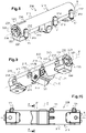
Fig. 1 ] est une vue schématique en perspective d'un côté d'un premier mode de réalisation du système de pivotement selon l'invention, - [
Fig. 2 ] est une vue schématique en perspective d'un côté opposé du système de pivotement de lafigure 1 , - [
Fig. 3 ] est une vue de dessus de lafigure 1 , - [
Fig. 4 ] est une vue en coupe selon le plan B-B de lafigure 3 , - [
Fig. 5 ] est une vue schématique en perspective partiellement éclatée du système de pivotement de lafigure 1 , - [
Fig. 6 ] est une vue schématique en perspective de la partie assemblée de lafigure 5 , - [
Fig. 7 ] est une vue éclatée de lafigure 6 , - [
Fig. 8 ] est une vue schématique en perspective d'un côté d'un deuxième mode de réalisation du système de pivotement selon l'invention, - [
Fig. 9 ] est une vue schématique en perspective d'un côté opposé du système de pivotement de lafigure 8 , - [
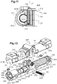
Fig. 10 ] est une vue de dessous de lafigure 8 , - [
Fig. 11 ] est une vue en coupe selon le plan A-A de lafigure 10 , - [
Fig. 12 ] est une vue schématique en perspective partiellement éclatée du système de lafigure 8 , - [
Fig. 13 ] est une vue schématique de dessus de la partie assemblée de lafigure 12 , - [
Fig. 14 ] est une vue schématique en perspective de lafigure 13 , et - [
Fig. 15 ] est une vue partielle éclatée de lafigure 14 .
- [
Fig. 1 ] is a schematic perspective view from one side of a first embodiment of the pivoting system according to the invention, - [
Fig. 2 ] is a schematic perspective view of an opposite side of the pivoting system of thefigure 1 , - [
Fig. 3 ] is a top view of thefigure 1 , - [
Fig. 4 ] is a sectional view according to plan BB of thepicture 3 , - [
Fig. 5 ] is a partially exploded schematic perspective view of the pivoting system of thefigure 1 , - [
Fig. 6 ] is a schematic perspective view of the assembled part of thefigure 5 , - [
Fig. 7 ] is an exploded view of thefigure 6 , - [
Fig. 8 ] is a schematic perspective view from one side of a second embodiment of the pivoting system according to the invention, - [
Fig. 9 ] is a schematic perspective view of an opposite side of the pivoting system of thefigure 8 , - [
Fig. 10 ] is a bottom view of thefigure 8 , - [
Fig. 11 ] is a sectional view according to plan AA of thefigure 10 , - [
Fig. 12 ] is a partially exploded schematic perspective view of the system of thefigure 8 , - [
Fig. 13 ] is a schematic top view of the assembled part of thefigure 12 , - [
Fig. 14 ] is a schematic perspective view of thefigure 13 , and - [
Fig. 15 ] is a partial exploded view of thefigure 14 .
Sur les différentes figures on a représenté deux modes de réalisation d'un système de pivotement 100 ; 200 d'un support d'appareillage (non représenté sur les figures).In the various figures, two embodiments of a
Un tel système de pivotement fait avantageusement partie d'un appareillage à encastrer dans une ouverture d'une paroi de réception dont le support d'appareillage est basculant pour disparaître sous cette paroi ou être accessible en saillie de celle-ci.Such a pivoting system advantageously forms part of an appliance to be built into an opening of a receiving wall, the appliance support of which tilts to disappear under this wall or to be accessible projecting from the latter.
La paroi de réception peut être une paroi d'un mobilier de bureau tel qu'une table de travail ou un meuble de rangement ou encore une paroi de plancher technique.The reception wall can be a wall of office furniture such as a work table or a storage unit or even a technical floor wall.
L'appareillage peut être une prise de courant, une prise USB, une prise RJ45, une prise téléphonique ou encore une prise d'antenne ou encore un bloc multiprise. Il pourrait s'agir d'un appareillage électronique.The equipment can be a power socket, a USB socket, an RJ45 socket, a telephone socket or even an aerial socket or even a power strip. It could be an electronic device.
Un exemple d'un tel appareillage est décrit en détail dans les documents brevets
Pour l'essentiel, un tel appareillage comporte :
- une plaque de façade se présentant sous la forme d'un cadre délimitant une ouverture centrale ;
- un support d'appareillage monté à basculement au travers de l'ouverture centrale de la plaque de façade, entre une position abaissée dans laquelle il s'étend en dessous de la plaque de façade et une position relevée dans laquelle il s'étend en majeure partie au-dessus de la plaque de façade;
- un système de
pivotement 100 ; 200 du support d'appareillage; et - un système de verrouillage, débrayable à l'aide d'une touche d'actionnement, pour bloquer le support d'appareillage dans l'une ou l'autre de ses positions abaissée et relevée.
- a front plate in the form of a frame delimiting a central opening;
- a device support mounted to tilt through the central opening of the faceplate, between a lowered position in which it extends below the faceplate and a raised position in which it extends over the major part part above the facade plate;
- a
pivoting system 100; 200 of the device support; and - a locking system, disengageable using an actuation button, to lock the device support in one or the other of its lowered and raised positions.
La plaque de façade de l'appareillage est une pièce avantageusement réalisée en matière métallique. Elle est destinée à s'appliquer contre la face avant de la paroi de réception de l'appareillage, autour de l'ouverture d'encastrement. Le bord extérieur de cette plaque de façade peut suivre un contour carré, rectangulaire ou circulaire ou encore oblong. L'ouverture centrale de cette plaque de façade peut être une ouverture carrée, rectangulaire, circulaire ou oblongue.The front plate of the apparatus is a part advantageously made of metallic material. It is intended to be applied against the front face of the receiving wall of the switchgear, around the recessed opening. The outer edge of this facade plate can follow a square, rectangular or circular outline or even oblong. The central opening of this face plate can be a square, rectangular, circular or oblong opening.
La face avant de la plaque de façade participe à l'esthétique de l'ensemble tandis que la face arrière de la plaque de façade porte des éléments techniques pour le logement et la fixation de différents éléments de l'appareillage. La face arrière de la plaque de façade présente une surface plane pour prendre appui contre la paroi de réception. Cette surface plane reçoit avantageusement un joint d'étanchéité à l'eau et aux poussières, ce joint permettant d'épouser les irrégularités éventuelles de la face avant de la paroi de réception.The front face of the facade plate contributes to the aesthetics of the whole while the rear face of the facade plate bears technical elements for housing and fixing various elements of the apparatus. The rear face of the front plate has a flat surface to bear against the receiving wall. This flat surface advantageously receives a seal against water and dust, this seal making it possible to conform to any irregularities of the front face of the receiving wall.
Le support d'appareillage est réalisé avantageusement en matière métallique. Il se présente sous la forme d'un boîtier parallélépipédique avec deux parois latérales principales parallèles qui s'étendent perpendiculairement au plan moyen du cadre de la plaque de façade, reliées entre elles par des poutres transversales, un carénage inférieur qui ferme l'espace interne défini entre lesdites parois latérales principales et un cadre de façade, rapporté entre les deux parois latérales principales et une des poutres du support d'appareillage, qui délimite une ou deux ouvertures d'accès à l'espace interne défini entre les parois latérales principales du support d'appareillage.The device support is advantageously made of metallic material. It is in the form of a parallelepipedal box with two parallel main side walls which extend perpendicularly to the middle plane of the frame of the facade plate, connected to each other by transverse beams, a lower fairing which closes the internal space defined between said main side walls and a front frame, attached between the two main side walls and one of the beams of the device support, which delimits one or two access openings to the internal space defined between the main side walls of the device support.
Des mécanismes d'appareillage sont rapportés dans la ou les ouvertures du cadre de façade de manière que les socles de ces mécanismes sont encliquetés ou emboîtés sur les montants de ce cadre de façade et s'étendent à l'intérieur dudit espace interne, et que les enjoliveurs ferment la ou lesdites ouvertures dudit cadre de façade.Device mechanisms are added in the opening or openings of the front frame so that the bases of these mechanisms are snapped or fitted onto the uprights of this front frame and extend inside said internal space, and that the covers close said opening(s) of said front frame.
La façade fonctionnelle de l'appareillage est formée par les faces avant fonctionnelles des enjoliveurs desdits mécanismes d'appareillage rapportés sur le support d'appareillage.The functional front of the switchgear is formed by the functional front faces of the covers of said switchgear mechanisms attached to the switchgear support.
L'appareillage comprend un couvercle destiné à fermer l'ouverture centrale de la plaque de façade lorsque le support d'appareillage est basculé en position abaissée. Le couvercle se présente sous la forme d'une plaque solidarisée par des vis aux parois latérales principales du support d'appareillage et montée à pivotement sur le cadre de la plaque de façade autour d'un axe parallèle à un côté de ladite plaque de façade.The apparatus comprises a cover intended to close the central opening of the facade plate when the apparatus support is tilted into the lowered position. The cover is in the form of a plate secured by screws to the main side walls of the device support and pivotally mounted on the frame of the front plate around an axis parallel to one side of said front plate. .
Une des parois latérales principales du support d'appareillage porte sur sa face externe, à proximité d'un bord arrière opposé à la façade fonctionnelle de l'appareillage, un élément de butée destiné à s'engager dans la rainure de butée de la plaque de façade lorsque le support d'appareillage bascule depuis sa position abaissée vers sa position relevée. La mise en butée de cet élément de butée contre le fond de la rainure de butée permet d'indexer la position stable relevée du support d'appareillage.One of the main side walls of the device support carries on its outer face, close to a rear edge opposite the functional front of the device, an abutment element intended to engage in the abutment groove of the plate facade when the device support tilts from its lowered position to its raised position. The abutment of this abutment element against the bottom of the abutment groove makes it possible to index the stable raised position of the device support.
Les parois latérales principales du support d'appareillage sont, à l'arrière dudit support, c'est-à-dire à l'opposé de la façade dudit support, liées par deux bielles aux deux extrémités d'un arbre d'entraînement en rotation du système de pivotement 100 ; 200. Ces bielles parallèles sont agencées de manière à transmettre le mouvement de rotation de l'arbre d'entraînement en rotation audit support d'appareillage.The main side walls of the device support are, at the rear of said support, that is to say opposite the front of said support, connected by two connecting rods to the two ends of a drive shaft in rotation of the
Comme le montrent plus particulièrement les
Selon une variante non représentée, on pourrait prévoir que le système de pivotement comprenne deux ressorts de torsion associés à deux amortisseurs comme c'est le cas dans le système de pivotement décrit dans les documents
Le boîtier 110 ; 210 présente une forme globalement cylindrique allongée selon un axe X. Il comporte aux extrémités deux ouvertures circulaires 111A ;211A. Il est formé de deux coques 111 ; 211 globalement semi cylindriques, positionnées bord à bord et solidarisées l'une à l'autre le long de leurs bords longitudinaux 111B,111C ; 211B,211C. Les moyens de solidarisation des deux coques 111 ; 211 comportent un système d'encliquetage et un système de vissage. Le système d'encliquetage comporte le long d'un bord longitudinal 111C ; 211C d'une des coques 111 ; 211 des dents 114 ; 214 et le long du bord longitudinal 111C ; 211C correspondant de l'autre coque 111 ; 211 des fenêtres 115 ; 215 dans lesquelles s'encliquètent les dents 114 ; 214. Le système de vissage comporte le long des deux autres bords longitudinaux correspondants 111B ; 211B des deux coques 111 ; 211 des cheminées taraudées 112 ; 212 dans lesquelles sont vissées des vis V1 (voir
Selon les exemples représentés sur les figures, en son centre, le boîtier 110 ; 210 loge ledit dispositif de réglage. A cet effet, il comporte un logement 116 ; 216 de forme adéquate qui accueille la roue dentée 150 ; 250 coopérant avec le filetage de la vis de réglage 170 ; 270 dont l'extrémité 171 ; 271 est engagée dans une encoche interne 117A ; 217A du boîtier 110 ; 210 et dont la tête de manœuvre 172 ; 272 est engagée dans une ouverture circulaire 117B ; 217B d'une face latérale du boîtier 110 ; 210, au travers de laquelle elle est accessible à un installateur (voir
Selon les premier et deuxième modes de réalisation du système de pivotement 100 ; 200 représentés sur les
Selon le premier mode de réalisation du système de pivotement 100 représenté sur les
Selon le deuxième mode de réalisation du système de pivotement 200 représenté sur les
Lorsque la roue dentée 250 est placée dans le logement 216 au centre du boîtier 210, les plots cylindriques 251, le plot supplémentaire 251B au profil hexagonal, le plot cylindrique d'extrémité 252B et l'axe de guidage 251A présentent comme axe commun l'axe X du boîtier 210.When the
La roue dentée 250, les plots cylindriques 251, le plot supplémentaire 251B au profil hexagonal, le plot cylindrique d'extrémité 252B et l'axe de guidage 251A appartiennent à une seule pièce monobloc métallique.The
Selon ce deuxième mode de réalisation, il est avantageusement prévu dans les deux coques 211 deux berceaux semi cylindriques 202 qui entourent le plot cylindrique d'extrémité 252B de façon à centrer la roue dentée 250 sur l'axe de rotation X. Ainsi, ici, les deux plots 251 liés directement à la roue dentée 250 et le plot cylindrique d'extrémité 252B lié indirectement à la roue dentée 250, sont entourés par des surfaces cylindriques 216A, 202 du boîtier 210, centrées sur l'axe X du boîtier 210, pour assurer le centrage de la roue dentée 250 sur ledit axe X du boîtier 210.According to this second embodiment, two
Quel que soit le mode de réalisation du système de pivotement 100 ; 200, il est prévu à l'intérieur du boîtier 110 ;210, de part et d'autre de la roue dentée 150 ;250, un système d'entraînement en rotation.Whatever the embodiment of the
Ce système d'entraînement en rotation comprend d'un côté de la roue dentée 150 ;250 (situé à gauche sur les
Lorsque ces deux parties 120,165 ;220,265 de l'arbre d'entraînement en rotation sont montées dans le boîtier 110 ;210, les axes X1 et X2 sont confondus avec l'axe X dudit boîtier 110 ;210 (voir
Ici, les première et deuxième parties 120, 165 ;220,265 de l'arbre d'entraînement en rotation sont différentes mais elles pourraient être identiques comme c'est le cas dans le système de pivotement décrit dans les documents
Chacune des première et deuxième parties 120,165 ;220,265 de l'arbre d'entraînement en rotation est une pièce monobloc métallique.Each of the first and second parts 120.165; 220.265 of the rotary drive shaft is a one-piece metal part.
La première partie 120 ;220 de l'arbre d'entraînement en rotation présente une extrémité pourvue d'une fente 121 ;221 et une extrémité pourvue d'un disque 122 ;222 qui ferme une ouverture circulaire 111A ;211A d'extrémité du boîtier 110 ;210. La face externe 123 ;223 du disque 122 ;222, c'est-à-dire la face du disque 122 ;222 tournée vers l'extérieur du boîtier 110;210 lorsque le disque 122 ;222 ferme l'ouverture circulaire 111A ;211A d'extrémité du boîtier 110 ;210, porte deux tétons 124 ;224 en saillie placés de manière diamétralement opposée par rapport au centre du disque 122 ;222.The
Selon le premier mode de réalisation du système de pivotement 100 représenté sur les
Selon le deuxième mode de réalisation du système de pivotement 200 représenté sur les
Enfin, la première partie 120 ;220 de l'arbre d'entraînement en rotation comporte un conduit taraudé 125 ;225 qui débouche au centre de la face externe 123 ;223 du disque 122 ;222.Finally, the
Le système d'entraînement en rotation comporte un amortisseur 140 ;240 lié à la première partie 120 ;220 de l'arbre d'entraînement en rotation.The rotation drive system comprises a
L'amortisseur 140 ;240 est tout à fait classique. Il comporte un cylindre externe 141 ;241 et un cylindre interne 144 concentriques autour de l'axe X ainsi qu'une matière visqueuse prévue entre les deux cylindres. Le cylindre externe 141 ;241 porte sur sa face externe une nervure 142 ;242 s'étendant suivant une génératrice du cylindre externe 141 ;241 (voir
La face externe d'un disque annulaire 143 ; 243 (celui situé du côté du disque 122 ;222 d'extrémité de la première partie 120 ;220 de l'arbre d'entraînement en rotation) porte deux plots 145 placés de manière diamétralement opposée par rapport au centre du disque annulaire 143 ;243.The outer face of an
Comme le montrent plus particulièrement les
Selon les exemples représentés sur les figures, l'ensemble formé par la première partie 120 ;220 de l'arbre d'entraînement en rotation et l'amortisseur 140 ;240 auquel il est lié, est dissocié de la roue dentée 150 ;250 en ce sens qu'il n'est prévu aucun élément pour établir une quelconque liaison mécanique entre cet ensemble et la roue dentée 150 ;250.According to the examples shown in the figures, the assembly formed by the
Bien entendu, on pourrait prévoir selon une variante non représentée, comme dans le système de pivotement décrit dans les documents
Comme le montrent les
La longueur de l'axe de guidage 160 lié à la deuxième partie 165 de l'arbre d'entraînement en rotation selon le premier mode de réalisation du système de pivotement 100 (voir les
Comme le montre plus particulièrement la
Comme le montrent plus particulièrement les
Avantageusement, selon le deuxième mode de réalisation, il est prévu sur la face intérieure 211E de chaque coque 211 du boîtier 210 une nervure 201 apte à se placer contre une face 262B du deuxième disque 262 tournée vers la face 263B correspondante du premier disque 263 de la deuxième partie 265 de l'arbre d'entraînement en rotation. Cette nervure 201 forme une butée qui limite les éventuels déplacements en translation selon l'axe X de la deuxième partie 265 de l'arbre d'entraînement.Advantageously, according to the second embodiment, there is provided on the
Enfin, la deuxième partie 165 ;265 de l'arbre d'entraînement en rotation comporte un conduit taraudé (non visible sur les figures) qui débouche au centre de la face externe 163A ;263A du premier disque 163 ;263.Finally, the
Selon les deux modes de réalisation représenté, le système d'entraînement en rotation comporte un ressort de torsion 180.According to the two embodiments shown, the rotation drive system includes a
Selon le premier mode de réalisation représenté sur la
Selon le deuxième mode de réalisation représenté sur les
Pour ajuster la contrainte de torsion du ressort de torsion 180 du système de pivotement 100 ;200, il suffit de visser ou de dévisser la vis de réglage 170 ;270 grâce à un tournevis dont la pointe est engagée dans la fente de la tête de manœuvre 172 ;272 de ladite vis de réglage 170 ;270, de façon à tourner la roue dentée 150 ;250 dans le sens adéquat. La roue dentée 150 ;250 entraîne en rotation le plot cylindrique 151 ;251 correspondant ainsi que, le cas échéant, l'axe de guidage 251A attaché audit plot cylindrique 251, qui provoque alors simultanément la mise sous contrainte ou le relâchement de la contrainte du ressort de torsion 180.To adjust the torsional stress of the
L'ajustement de la contrainte du ressort de torsion 180 permet d'ajuster le couple de pivotement de la deuxième partie 165 ;265 de l'arbre d'entraînement en rotation et donc de l'arbre d'entraînement en rotation lui-même.Adjusting the stress of the
Ce couple de pivotement est amorti grâce à l'amortisseur 140 ;240.This pivoting torque is dampened by the
Selon une caractéristique remarquable du système de pivotement 100 ;200, il est prévu un élément de blocage V2 ; V3, distinct de la vis de réglage 170 ;270, qui coopère directement ou indirectement avec la roue dentée 150 ;250 pour bloquer la rotation de cette roue dentée 150 ;250 autour de son axe X, X1.According to a remarkable characteristic of the
Ici, quel que soit le mode de réalisation représenté sur les différentes figures, l'élément de blocage est avantageusement une vis de blocage V2 ; V3.Here, regardless of the embodiment shown in the various figures, the locking element is advantageously a locking screw V2; V3.
Comme le montrent les
Ici, le conduit traversant 119 ; 219 est un conduit taraudé dans lequel la vis de blocage V2 ; V3 est vissée (voir les
Le conduit traversant 119 ; 219 s'étend au travers d'une des deux coques 111 ; 211 selon un axe longitudinal Y ; Z1 transversal à l'axe longitudinal X dudit boîtier 110 ; 210.The through
Selon le premier mode de réalisation du système de pivotement 100 représenté sur les
Selon ce premier mode de réalisation, ledit conduit traversant 119 traverse l'épaisseur de la paroi de la coque 111 et débouche à l'intérieur du boîtier 110 au droit d'un cran 150A du crantage de ladite roue dentée 150 (voir
Après avoir ajuster la contrainte du ressort de torsion 180 en vissant et/ou en dévissant la vis de réglage 170 pour tourner la roue dentée 150, on visse la vis de blocage V2 au travers du conduit traversant 119, à l'aide d'un tournevis dont la pointe est introduite dans l'empreinte de la vis de blocage V2, de sorte que la pointe d'extrémité VE2 de la vis de blocage V2 est engagée dans ledit cran 150A de ladite roue dentée 150 et bloque la rotation de ladite roue dentée 150.After having adjusted the constraint of the
Selon le deuxième mode de réalisation du système de pivotement 200 représenté sur les
Selon ce deuxième mode de réalisation, ledit conduit traversant 219 débouche à l'intérieur du boîtier 210 de manière décalée par rapport à ladite roue dentée 250, au droit d'un plot solidaire de ladite roue dentée 250. Le plot dont il s'agit ici, est le plot supplémentaire 251B au profil hexagonal. Le conduit traversant 219 présente une entrée qui traverse l'épaisseur d'une partie latérale de la paroi de la coque 211 correspondante du boîtier 210 et qui accueille la tête de la vis de blocage V3. Le conduit traversant 219 comporte une sortie qui traverse l'épaisseur d'une autre partie latérale de la paroi de la coque 111 du boîtier 210 (voir
Après avoir ajusté la contrainte du ressort de torsion 180 en vissant et/ou en dévissant la vis de réglage 270 pour tourner la roue dentée 250, on visse la vis de blocage V3 au travers du conduit traversant 219 de sorte qu'une partie du filetage de son corps fileté VC3 accroche la surface externe hexagonal du plot supplémentaire 251B solidaire de ladite roue dentée 250 et bloque la rotation de ladite roue dentée 250.After having adjusted the stress of the
Grâce à ce blocage, on évite qu'après un grand nombre de cycles de fonctionnement du système de pivotement 100 ; 200, la vis de réglage 170 ;270 ne se desserre et provoque un relâchement de la contrainte du ressort de torsion 180 ce qui peut entraîner une perte de puissance du système de pivotement à l'ouverture du support d'appareillage.Thanks to this blocking, it is avoided that after a large number of operating cycles of the
Le boîtier 110 ;210 fermé logeant l'ensemble des éléments décrits ci-dessus, est vissé à l'arrière du cadre de la plaque de façade.The
L'arbre d'entraînement à rotation du système de pivotement 100 ; 200 est lié à des bielles qui coopèrent de manière glissante avec ledit support d'appareillage. Les bielles comprennent à cet effet un orifice central et plusieurs orifices périphériques disposés en cercle autour de l'orifice central. Les tétons 124,164 ;224,264 des disques 122,163; 222,263 d'extrémité des deux parties de l'arbre d'entraînement en rotation sont engagés dans deux orifices périphériques des bielles. En outre, une vis est engagée au travers de l'orifice central de chaque bielle et est vissée dans le conduit taraudé 125 ; 225 de la partie correspondante de l'arbre d'entraînement de rotation. De cette manière, les bielles sont solidement solidarisées aux deux disques 122,163 ; 222,263 d'extrémité de l'arbre d'entraînement en rotation.The rotation drive shaft of the
Quel que soit le mode de réalisation représenté, le système de verrouillage de l'appareillage comprend de manière connue en soit, d'une part, au moins un bras de verrouillage déplaçable entre une position de verrouillage dans laquelle une partie de blocage dudit bras de verrouillage prend appui contre une surface de blocage du support d'appareillage et une position de libération dans laquelle ladite partie de blocage est écartée de ladite surface de blocage, et, d'autre part, une touche d'actionnement pour la commande du déplacement de chaque bras de verrouillage. Il est également prévu des moyens élastiques de rappel du bras de verrouillage dans sa position de verrouillage.Whatever the embodiment shown, the apparatus locking system comprises in known manner either, on the one hand, at least one locking arm movable between a locking position in which a locking part of said locking arm lock bears against a blocking surface of the device support and a release position in which said blocking part is spaced from said blocking surface, and, on the other hand, an actuating button for controlling the movement of each locking arm. There are also provided elastic means for recalling the locking arm to its locking position.
A l'état fermé de l'appareillage, le support d'appareillage est maintenu en position abaissée sous la plaque de façade par le bras de verrouillage. Pour ouvrir l'appareillage, l'utilisateur appuie avec un doigt sur la touche d'actionnement pour libérer le support d'appareillage dudit bras de verrouillage. Le ressort de torsion 180 du système de pivotement 100 ; 200 libère alors son énergie de torsion et provoquent le pivotement de l'arbre d'entrainement en rotation 120,165 ; 220,265. Celui-ci entraîne en pivotement les deux bielles qui glissent contre le support d'appareillage et entraînent en rotation le support d'appareillage qui pivote jusqu'à atteindre sa position relevée au-dessus de la plaque de façade, donc au-dessus de la paroi de réception.In the closed state of the apparatus, the apparatus support is held in the lowered position under the front plate by the locking arm. To open the device, the user presses with a finger on the actuating key to release the device holder from said locking arm. The
Le support d'appareillage atteint sa position relevée stable lorsque son élément de butée arrive en butée au fond de la rainure de butée de la plaque de façade.The device carrier reaches its stable raised position when its stop element comes into abutment at the bottom of the stop groove of the facade plate.
Dans cette position relevée, la façade fonctionnelle de l'appareillage est accessible à l'utilisateur au-dessus de la paroi de réception.In this raised position, the functional front of the apparatus is accessible to the user above the receiving wall.
Pour fermer l'appareillage, il suffit d'exercer une pression sur le couvercle de l'appareillage de manière à faire basculer le support d'appareillage vers sa position abaissée sous la plaque de façade et donc sous la paroi de réception. Ce basculement inverse provoque le basculement inverse des bielles et donc le pivotement de l'arbre d'entraînement en rotation qui entraîne la torsion du ressort de torsion 180 du système de pivotement 100 ; 200. Ce ressort de torsion 180 emmagasine alors de nouveau de l'énergie de torsion. La position abaissée du support d'appareillage est atteinte lorsque la partie de blocage du bras de verrouillage prend appui contre la surface de blocage du support d'appareillage.To close the apparatus, it suffices to exert pressure on the lid of the apparatus so as to tilt the apparatus support towards its lowered position under the front plate and therefore under the receiving wall. This reverse tilting causes the reverse tilting of the connecting rods and therefore the pivoting of the drive shaft in rotation which causes the torsion of the
L'invention n'est pas limitée à la description détaillée et diverses autres modifications peuvent y être apportées.The invention is not limited to the detailed description and various other modifications may be made thereto.
Bien entendu, diverses autres modifications peuvent aussi être apportées à l'invention dans le cadre des revendications annexées.Of course, various other modifications may also be made to the invention within the scope of the appended claims.
Claims (12)
Applications Claiming Priority (1)
| Application Number | Priority Date | Filing Date | Title |
|---|---|---|---|
| CN202120441780.9U CN214754256U (en) | 2021-03-01 | 2021-03-01 | Damping device for flick type socket |
Publications (3)
| Publication Number | Publication Date |
|---|---|
| EP4053369A1 true EP4053369A1 (en) | 2022-09-07 |
| EP4053369C0 EP4053369C0 (en) | 2024-03-13 |
| EP4053369B1 EP4053369B1 (en) | 2024-03-13 |
Family
ID=78590620
Family Applications (1)
| Application Number | Title | Priority Date | Filing Date |
|---|---|---|---|
| EP22158269.5A Active EP4053369B1 (en) | 2021-03-01 | 2022-02-23 | System for pivoting a switchgear mounting and switchgear for installation comprising such a pivoting system |
Country Status (2)
| Country | Link |
|---|---|
| EP (1) | EP4053369B1 (en) |
| CN (1) | CN214754256U (en) |
Citations (4)
| Publication number | Priority date | Publication date | Assignee | Title |
|---|---|---|---|---|
| CN203850477U (en) * | 2014-04-30 | 2014-09-24 | 温州西诺电工科技有限公司 | Adjustable damping device of ground socket |
| US20150218864A1 (en) * | 2014-02-05 | 2015-08-06 | Zero Zone, Inc. | Door closer mechanism for display case |
| US20200291681A1 (en) * | 2019-03-12 | 2020-09-17 | Ford Global Technologies, Llc | Locking mechanism for a motor |
| FR3103642A1 (en) | 2019-11-26 | 2021-05-28 | Legrand France | Switchgear with tilting switchgear support |
-
2021
- 2021-03-01 CN CN202120441780.9U patent/CN214754256U/en active Active
-
2022
- 2022-02-23 EP EP22158269.5A patent/EP4053369B1/en active Active
Patent Citations (5)
| Publication number | Priority date | Publication date | Assignee | Title |
|---|---|---|---|---|
| US20150218864A1 (en) * | 2014-02-05 | 2015-08-06 | Zero Zone, Inc. | Door closer mechanism for display case |
| CN203850477U (en) * | 2014-04-30 | 2014-09-24 | 温州西诺电工科技有限公司 | Adjustable damping device of ground socket |
| US20200291681A1 (en) * | 2019-03-12 | 2020-09-17 | Ford Global Technologies, Llc | Locking mechanism for a motor |
| FR3103642A1 (en) | 2019-11-26 | 2021-05-28 | Legrand France | Switchgear with tilting switchgear support |
| EP3829015A1 (en) | 2019-11-26 | 2021-06-02 | Legrand France | Appliance with tilting appliance mounting |
Also Published As
| Publication number | Publication date |
|---|---|
| CN214754256U (en) | 2021-11-16 |
| EP4053369C0 (en) | 2024-03-13 |
| EP4053369B1 (en) | 2024-03-13 |
Similar Documents
| Publication | Publication Date | Title |
|---|---|---|
| FR2588607A1 (en) | STORE WITH LATERAL TRACTION. | |
| FR2728451A1 (en) | ROTARY SHOCK ABSORBER FOR SWIVEL COVER, WITH SELF-LOCKING MECHANISM IN VERTICAL POSITION | |
| WO1996035890A1 (en) | Hydrokinetic coupling apparatus, particularly for a motor vehicle | |
| EP4053369B1 (en) | System for pivoting a switchgear mounting and switchgear for installation comprising such a pivoting system | |
| FR2907080A1 (en) | Windscreen wiper arm fixing device for motor vehicle, has blocking unit blocking male unit in female cavity, and male unit comes in contact with windscreen wiper arm, where blocking unit has leaf spring projection in cavity at relaxed state | |
| EP1087075A1 (en) | Permanent anchoring device | |
| EP3829015B1 (en) | Appliance with tilting appliance mounting | |
| EP0551234B1 (en) | Appliance, such as an electrical domestic appliance, fitted with a door with horizontal swinging axle and a device counterbalancing the door weight intended for being fitted with a trimpanel | |
| EP2516778A2 (en) | Shutter device and corresponding assembly | |
| EP2927536B1 (en) | Linear actuator and associated concealment device | |
| CA2716389A1 (en) | Mobile casing device | |
| FR3096714A3 (en) | Comb type hinge for window and swing leaf doors | |
| EP1059409A1 (en) | Drive gear for a lock follower | |
| EP0691448A1 (en) | Door hinge having stop notches, particularly in an automotive vehicle | |
| FR2652374A1 (en) | HANDLE FOR A VEHICLE DOOR WITH A MOTOR. | |
| EP3829014A1 (en) | Appliance with tilting appliance mounting and a locking system releasable by means of a tilting activation key | |
| FR2799805A1 (en) | Wall anchor for safety fitment such as ladder or platform has spacer bush under head to receive coupling member on fitment | |
| FR2780208A1 (en) | Cabinet with hinged or detachable cover options for housing electrical equipment | |
| FR2658236A1 (en) | Assembly for producing a countersash windowframe | |
| EP0841449B1 (en) | Monodirectional esplagnolette | |
| FR2730264A1 (en) | Door handle to leaf assembly | |
| EP0119361B1 (en) | Framing profile for a swinging compound window | |
| FR2666369A1 (en) | Fitting for a window, door or the like | |
| EP0225222B1 (en) | Electrical apparatus with improved assembly | |
| EP2632002B1 (en) | Sealed electrical appliance with buffer element |
Legal Events
| Date | Code | Title | Description |
|---|---|---|---|
| PUAI | Public reference made under article 153(3) epc to a published international application that has entered the european phase |
Free format text: ORIGINAL CODE: 0009012 |
|
| STAA | Information on the status of an ep patent application or granted ep patent |
Free format text: STATUS: THE APPLICATION HAS BEEN PUBLISHED |
|
| AK | Designated contracting states |
Kind code of ref document: A1 Designated state(s): AL AT BE BG CH CY CZ DE DK EE ES FI FR GB GR HR HU IE IS IT LI LT LU LV MC MK MT NL NO PL PT RO RS SE SI SK SM TR |
|
| STAA | Information on the status of an ep patent application or granted ep patent |
Free format text: STATUS: REQUEST FOR EXAMINATION WAS MADE |
|
| 17P | Request for examination filed |
Effective date: 20220905 |
|
| RBV | Designated contracting states (corrected) |
Designated state(s): AL AT BE BG CH CY CZ DE DK EE ES FI FR GB GR HR HU IE IS IT LI LT LU LV MC MK MT NL NO PL PT RO RS SE SI SK SM TR |
|
| GRAP | Despatch of communication of intention to grant a patent |
Free format text: ORIGINAL CODE: EPIDOSNIGR1 |
|
| STAA | Information on the status of an ep patent application or granted ep patent |
Free format text: STATUS: GRANT OF PATENT IS INTENDED |
|
| RIC1 | Information provided on ipc code assigned before grant |
Ipc: F16H 57/039 20120101ALI20230928BHEP Ipc: F16H 19/00 20060101ALI20230928BHEP Ipc: F16H 1/16 20060101ALI20230928BHEP Ipc: E05F 1/12 20060101ALI20230928BHEP Ipc: E05F 1/10 20060101ALI20230928BHEP Ipc: E05F 3/22 20060101ALI20230928BHEP Ipc: E05F 3/14 20060101AFI20230928BHEP |
|
| INTG | Intention to grant announced |
Effective date: 20231025 |
|
| GRAS | Grant fee paid |
Free format text: ORIGINAL CODE: EPIDOSNIGR3 |
|
| GRAA | (expected) grant |
Free format text: ORIGINAL CODE: 0009210 |
|
| STAA | Information on the status of an ep patent application or granted ep patent |
Free format text: STATUS: THE PATENT HAS BEEN GRANTED |
|
| AK | Designated contracting states |
Kind code of ref document: B1 Designated state(s): AL AT BE BG CH CY CZ DE DK EE ES FI FR GB GR HR HU IE IS IT LI LT LU LV MC MK MT NL NO PL PT RO RS SE SI SK SM TR |
|
| REG | Reference to a national code |
Ref country code: GB Ref legal event code: FG4D Free format text: NOT ENGLISH |
|
| REG | Reference to a national code |
Ref country code: CH Ref legal event code: EP |
|
| REG | Reference to a national code |
Ref country code: DE Ref legal event code: R096 Ref document number: 602022002300 Country of ref document: DE |
|
| REG | Reference to a national code |
Ref country code: IE Ref legal event code: FG4D Free format text: LANGUAGE OF EP DOCUMENT: FRENCH |
|
| U01 | Request for unitary effect filed |
Effective date: 20240318 |
|
| U07 | Unitary effect registered |
Designated state(s): AT BE BG DE DK EE FI FR IT LT LU LV MT NL PT SE SI Effective date: 20240325 |