EP2632002B1 - Sealed electrical appliance with buffer element - Google Patents
Sealed electrical appliance with buffer element Download PDFInfo
- Publication number
- EP2632002B1 EP2632002B1 EP20120305204 EP12305204A EP2632002B1 EP 2632002 B1 EP2632002 B1 EP 2632002B1 EP 20120305204 EP20120305204 EP 20120305204 EP 12305204 A EP12305204 A EP 12305204A EP 2632002 B1 EP2632002 B1 EP 2632002B1
- Authority
- EP
- European Patent Office
- Prior art keywords
- cover
- electrical appliance
- lock
- mounting element
- trim
- Prior art date
- Legal status (The legal status is an assumption and is not a legal conclusion. Google has not performed a legal analysis and makes no representation as to the accuracy of the status listed.)
- Active
Links
- 230000032683 aging Effects 0.000 claims description 17
- 230000009467 reduction Effects 0.000 claims description 12
- 238000009434 installation Methods 0.000 claims description 7
- 239000002184 metal Substances 0.000 claims description 3
- 230000000750 progressive effect Effects 0.000 claims description 3
- 230000000694 effects Effects 0.000 description 11
- 230000035882 stress Effects 0.000 description 10
- 230000006835 compression Effects 0.000 description 9
- 238000007906 compression Methods 0.000 description 9
- 230000007423 decrease Effects 0.000 description 7
- 238000007789 sealing Methods 0.000 description 4
- 230000000295 complement effect Effects 0.000 description 3
- 230000000284 resting effect Effects 0.000 description 3
- 238000006073 displacement reaction Methods 0.000 description 2
- 239000002245 particle Substances 0.000 description 2
- 230000009471 action Effects 0.000 description 1
- 230000015556 catabolic process Effects 0.000 description 1
- 230000008859 change Effects 0.000 description 1
- 230000002950 deficient Effects 0.000 description 1
- 238000006731 degradation reaction Methods 0.000 description 1
- 230000002542 deteriorative effect Effects 0.000 description 1
- 238000010616 electrical installation Methods 0.000 description 1
- 230000002431 foraging effect Effects 0.000 description 1
- 239000007788 liquid Substances 0.000 description 1
- 238000004519 manufacturing process Methods 0.000 description 1
- 239000000463 material Substances 0.000 description 1
- 239000012528 membrane Substances 0.000 description 1
- 230000004048 modification Effects 0.000 description 1
- 238000012986 modification Methods 0.000 description 1
- 229920000642 polymer Polymers 0.000 description 1
- 230000000717 retained effect Effects 0.000 description 1
- 238000006467 substitution reaction Methods 0.000 description 1
- 230000007704 transition Effects 0.000 description 1
- XLYOFNOQVPJJNP-UHFFFAOYSA-N water Substances O XLYOFNOQVPJJNP-UHFFFAOYSA-N 0.000 description 1
Images


Classifications
-
- H—ELECTRICITY
- H02—GENERATION; CONVERSION OR DISTRIBUTION OF ELECTRIC POWER
- H02G—INSTALLATION OF ELECTRIC CABLES OR LINES, OR OF COMBINED OPTICAL AND ELECTRIC CABLES OR LINES
- H02G3/00—Installations of electric cables or lines or protective tubing therefor in or on buildings, equivalent structures or vehicles
- H02G3/02—Details
- H02G3/08—Distribution boxes; Connection or junction boxes
- H02G3/14—Fastening of cover or lid to box
-
- H—ELECTRICITY
- H02—GENERATION; CONVERSION OR DISTRIBUTION OF ELECTRIC POWER
- H02G—INSTALLATION OF ELECTRIC CABLES OR LINES, OR OF COMBINED OPTICAL AND ELECTRIC CABLES OR LINES
- H02G3/00—Installations of electric cables or lines or protective tubing therefor in or on buildings, equivalent structures or vehicles
- H02G3/02—Details
- H02G3/08—Distribution boxes; Connection or junction boxes
- H02G3/088—Dustproof, splashproof, drip-proof, waterproof, or flameproof casings or inlets
Definitions
- the field of the present invention is that of apparatus for electrical installation for the building, and the invention more particularly as object a particular electrical device.
- a seal as described above sometimes takes the form of a seal extending along a closed contour, conventionally following, for example, the upper edge of the possible mounting box, see for example EP 1 253 609 .
- This seal can also take the form of a membrane, as in DE 102 34 727 or EP 0 122 465 .
- this seal is subject to aging, and its elastic properties, guaranteeing its sealing capabilities, are deteriorating over time.
- the cover is normally fixed and maintained at a distance sufficiently close to the mounting element for the interface seal to be compressed, the stress corresponding to this constant deformation decreases gradually over time, under the effect of aging. The tightness provided is therefore no longer optimal.
- the present invention is intended to overcome at least this disadvantage by proposing to compensate for the effect of aging of the interface joint by increasing its compression deformation as soon as the associated stress tends to decrease.
- the subject of the invention is an electrical appliance, such as, for example, a switch and / or a connection socket for electrical plug, intended to be mounted projecting against or embedded in a wall, comprising at least one electrical function block, a mounting member for wall mounting and fixing said at least one functional block, such as a box for a surface mounting or a flat support for a flush mounting, and a cover, defining a main plane, forming the front of the electrical apparatus visible after installation, and placed on the mounting element.
- an electrical appliance such as, for example, a switch and / or a connection socket for electrical plug
- This electrical apparatus is characterized in that it comprises an interface joint between the mounting element and the cover, as well as at least one cover fixing means, adapted to fix said cover directly to the mounting element. and comprising at least one buffer element, deformed when the lid is attached to the mounting element and able to compensate at least partially, by a gradual reduction of its own deformation in time, the aging that takes place in the joint of interface.
- the subject of the invention is therefore an electrical appliance 1, such as, for example, a switch and / or connection socket for electrical plug, intended to be mounted projecting against or embedded in a wall, comprising at least one electrical functional block, a mounting member 4 for mounting to the wall and fixing said at least one functional block, such as a box for a surface mounting or a flat support for a flush mounting, and a cover 5, defining a main plane 12, forming the front of the electrical apparatus 1 visible after installation, and placed on the mounting element 4.
- the cover 5 may allow the user to interact with the at least one functional block, such as allow him to connect an electrical plug to a power unit of the base type or to switch a function block of the switch type.
- the cover 5 may alternatively completely close the mounting element 4 by making the at least one functional block inaccessible.
- the at least one functional block is then controlled by at least one handle 28 present in the cover 5 and on which a user can act, the functional block can be monostable or bistable, said unless a lever 28 is generally removable.
- the cover 5 can also fulfill a display function, for example by integrating a screen. As will be described later, the cover 5 can also take the form of a plate 20 in which at least one trim 21 is mounted.
- the main plane 12 is parallel to the wall.
- the electrical apparatus 1 comprises an interface joint 26 between the mounting element 4 and the cover 5, as well as at least one cover fixing means 6, capable of fixing said cover 5 directly.
- the mounting element 4 comprising at least one buffer element 3, deformed when the cover 5 is fixed to the mounting element 4 and able to compensate at least partially, by a gradual reduction of its own deformation in time, the aging which takes place in the interface joint 26, this aging being in particular due to a relaxation of stress in the interface joint 26, generally made of polymer.
- the at least one attachment means 6 is masked by a switch lever 28, which allows for a discrete mounting.
- the interface seal 26 makes it possible to guarantee the tightness of the contact zone between the mounting element 4 and the cover 5, and is therefore compressed when the cover 5 is correctly mounted against the mounting element 4 , at least immediately after the first mounting of the cover 5.
- the at least one fastening means 6 directly attaches the cover 5 to the mounting member 4, sufficiently close so that the interface seal 26 is normally compressed. It may, for example, be of a simple screw. An advantageous embodiment of the fastening means 6 is described below.
- the at least one fastening means 6 attach the cover 5 to the mounting member 4 with sufficient force to permanently compress the interface seal 26 between them.
- the fastening means 6 thus exerts on the cover 5 a force sufficient for the interface seal 26 to be compressed, at least after installation.
- the cover 5, once installed remains in its position sufficiently close to the mounting element 4 so that the fastening means 6 is compressed, but is not tightened after installation. The deformation imposed on the interface joint 26 is therefore constant.
- the interface seal 26 is subject to aging, in particular by stress relaxation, which essentially consists of a gradual reduction of the force that the interface seal 26 opposes to its own deformation, the latter resulting in fact from the holding the cover 5 in position against the mounting element 4, under the action of the at least one fastening means 6.
- the aging thus has the effect of reducing the capabilities of the interface seal 26, and therefore also the sealing that it helps to get.
- the buffer element 3 thus has the effect of progressively compensating over time for this aging, and more particularly the relaxation of stresses, by slowing the reduction of the pressure exerted on the interface joint 26, between the cover 5 and the element. 4. To do this, it is the deformation imposed on the interface joint 26 which is gradually increased. In the absence of such a buffer element 3, it is essentially the deformation of the interface joint 26 that the at least one fastening means 6 maintains substantially constant, which leads to the relaxation of stresses described above. As described below, the buffer element 3 progressively reduces the space available for the interface seal 26 as the interface seal 26 reduces its resistance to deformation.
- FIG. 10a illustrates the role of the buffer element 3.
- FIG. figure 10a shows a situation where both the interface joint 26 and the buffer element 3 are deformed.
- the deformation of the interface seal 26 does not change, but the associated pressure on the interface seal 26 decreases gradually over time, which has the effect of damaging the seal .
- the buffer element 3 is less subject to stress relaxation than the interface joint 26, the aging of the latter is compensated for by the reduction, in time, of the deformation by compression of the buffer element 3, figure 10b .
- the buffer element 3 therefore has the effect of gradually reducing the space available for the interface seal 26 in time. This reduction thus tends to compensate for the decrease in the pressure experienced by the interface seal 26.
- the cover 5 comprises, firstly, a plate 20 having at least one opening 31, and, d on the other hand, at least one embellisher 21 compatible with the at least one functional block and placed in said at least one opening 31 as well as at least one inner seal 27 installed between said plate 20 and said at least one hubcap 21, the means 6 acting on the at least one trim 21 so that the plate 20 is held between said at least one trim 21 and the mounting element 4, the buffer element 3 being further able to compensate, by a progressive reduction of its deformation, the aging which takes place in the at least one internal seal 27, in particular the relaxation of stresses.
- the plate 20 may be standard, while the hubcap 21 is specific to the functional block.
- the hubcap 21 may be, for example, a hubcap 21 comprising a well 29 for electrical plug or comprising a switch lever 28 and its base 30.
- the compensation for aging in the at least one internal seal 27 is the same as that described for the interface seal 26.
- the cover 5 is thus in at least two parts, namely the plate 20 and at least one trim 21, at least one inner seal 27 must be mounted in the cover 5 to ensure the tightness of the cover 5 itself.
- the inner seal 27 is in the form of a section of material extending along a closed contour, placed around the opening 31, such as an O-ring or a lip seal.
- the at least one internal seal 27 can be obtained by overmoulding on the plate 20, or even the trim 21, or take the form of an independent piece, mounted in the cover 5.
- the aging of the inner seal 27, placed between the hubcap and the plate 20, is, in the same way as for the interface joint, between the plate 20 and the mounting element 4, compensated by the buffer element 3.
- the electrical apparatus 1 has a plurality of functional blocks, possibly different, a single cover 5, comprising a single plate 20 and a plurality of trim 21, each hubcap 21 corresponding to a functional block, each hub cover 21 being held by at least two fastening means 6.
- the cover 5 has a plurality of hubcaps 21 and therefore as many openings 31 and internal seals 27 guaranteeing the seal between the plate 20 and the hubcap 21. In this case, it is particularly interesting to make the internal seals 27 in one piece.
- the at least one cover fixing means 6 is able, on the one hand, in a so-called locked position of a latch 7 that comprises the at least one attachment means 6, to hold the cover 5 directly relative to the mounting element 4, and, secondly, in a so-called free position of said latch 7, not to hold the cover 5 relative to the mounting element 4, the passage of the position locked in the free position by rotating less than a turn of said latch 7 about an axis 8 substantially perpendicular to the main plane 12, in particular a quarter turn, which makes it possible to mount the cover 5 on the particularly ergonomic mounting element 4.
- the transition from the locked position to the free position is done without translation parallel to the axis 8, which allows the installer not to assimilate this locking or unlocking movement to a fixing movement of a screw provided. a thread.
- one end of the latch 7 bears on the cover 5, preferably on the plate 20, in particular on the base 30 for a switch, the other end bearing on the mounting element 4, which therefore allows the at least one fastening means 6 to directly hold the cover 5 to the mounting member 4.
- the latch 7 essentially takes the form of a rod 10, having a body 11 and, on the one hand, a head 9 for its actuation, said body 11 being thinner than said head 9, and on the other hand, a tip 17 having at least one flange 18, projecting from the body 11 of the rod 10, which allows the latch 7 to be retained relative to the mounting element 4 and relative to the lid 5, on the one hand, thanks to said at least one flange 18 resting in the mounting element 4, and, on the other hand, thanks to the head 9 resting in the cover 5.
- the fact of passing from the locking position in the free position has the effect of disengaging from its stop the head 9 and / or the at least one wing 18 of the tip 17.
- grooves 19 for actuation by means of a flat tool type screwdriver are provided on the lock 7, in particular on the or a head 9 of a rod 10 which forms the lock 7. It is thanks to these grooves that the installer can create the rotational movement to move from the locked position to the free position and vice versa.
- the at least one a fixing means 6 comprises at least one locking support surface 13 for the latch 7, against which the latter can rest to hold the cover 5 to the mounting element 4 in the locked position, in particular a surface of locking support 13 arranged on the buffer element 3.
- the lid 5 is thus held against the mounting element 4 by the latch 7, resting, for its head 9, in the lid 5, and for its tip 17 , in particular the flange 18, on the locking bearing surface 13.
- the lid 5 When the latch 7 bears against the locking bearing surface 13, the lid 5 is kept sufficiently close to the mounting element 4 so that the buffer element 3 and 1 interface seal 26 n / a are compressed, in a complementary manner as described above, as well as, in the same way, the at least one possible internal seal 27.
- the at least one fastening means 6 comprises at least one guiding surface 14 in the extension of the at least one locking bearing surface 13, on which the lock 7 can circulate to the at least one locking bearing surface 13 by bringing the cover 5 closer to the mounting element 4.
- the flange circulates on the guiding surface 14, which has a helical shape, which has the effect of bringing the cover 5 of the mounting element 4, and therefore to compress the element buffer 3 and the interface joint 26, as well as the at least one possible internal seal 27. It is therefore not necessary to press the cover 5 against the mounting element 4 before moving from the free position to the locking position, since the circulation on the guide surface 14 has the effect of bringing the cover 5 of the mounting element 4.
- the mounting of the cover is therefore easier for the installer.
- the guide surface 14 thus takes the form of a helix which transforms the rotational movement of the latch 7 into a translation movement.
- the flange 18 is in abutment against the locking bearing surface 13.
- An inverse movement must be made to move from the locking position to the free position.
- the wing 18 then leaves the locking bearing surface 13 and circulates on the guide surface 14, progressively allowing the head 9 to move away from the mounting element 4 and is therefore to the cover 5, taken between them, to move away too.
- the wing 18 then leads to a first clearance 16 arranged in the mounting element 4, which allows to completely detach the cover 5, since the wing 18 is then more restrained against the mounting element 4 but can freely circulate the first clearance 16.
- the buffer element 3 carries the at least one locking support surface 13 as well as the at least one guiding surface 14 and takes the form of an insert 15 placed inside the mounting member 4, and deformed when the latch 7 is in the locking position.
- the use of an insert makes it easier to manufacture the buffer element 4.
- the insert 15 is a metal washer, which guarantees a longer duration of the aging compensation. This metal washer is placed in the mounting element 4, and has a cutout allowing it to be traversed by the tip 17 of the latch 7, in particular a cut in the form of an oblong hole in the case where the tip 17 presents two wings 18.
- the at least one fixing means 6 has, at the level of the mounting element 4, a first orifice 23 in which the body 11 of the rod 10 can slide and pivot, as well as at least a first clearance 16 in which the at least one wing 18 can slide when the latch 7 is in the free position, thus making it possible to disengage the cover 5 and the latch 7 with respect to the mounting element 4 when said latch 7 is in the free position
- the at least one fastening means 6 has a through hole 38, arranged in the cover 5, in particular in the at least one hubcap 21 or a hubcap 21 that includes the cover 5, in which the body 11 of the rod 10 can slide and rotate but in which the head 9 can not circulate, and at least a second clearance 32 in which the at least one wing 18 can slide.
- the passage opening 38 and the second clearance 32 are arranged in a hollow stud 24 of the cover 5 accommodated in a passage 37 in the plate 20 or a plate 20 that includes the cover 5, thus making it possible to disengage the at least a latch 7 of the cover 5 by passing the tip 17. If the at least a second clearance 32 of the cover 5 is located vis-à-vis the first clearance 16 of the mounting member 4 when the cover 5 is mounted on said mounting element 4, the latch 7 can, in its free position, be disengaged from both the cover 5 and the mounting element 4.
- the tip 17 is provided with two wings 18 projecting from the body 11 of the rod 10 and diametrically opposed, the free position and the locked position being separated by a quarter-turn rotation.
- the various other elements of the fastening means 6 and the apparatus 1 itself are adapted to this number of flanges 18: the passage opening 38 is provided with two diametrically opposed second recesses 32, the first orifice 23 is provided with two diametrically opposed first clearances 16 thus making it possible to move from the free position to the locked position independently of the direction of rotation of the at least one lock 7, the fastening means 6 has two diametrically opposite locking bearing surfaces 13 and two adapted guide surfaces 14, the insert 15 having an oblong hole for the simultaneous passage of the two wings 18.
- a different number of wings 18 and different angular differences are possible.
- the at least one fastening means 6 has at least one lug 34 and at least one housing 35 for said lug 34, arranged so as to limit the translation of the latch 7, relative to to the cover 5, parallel to the axis 8, in particular a housing 35 in the form of a circumferential groove, the lug 34 and the housing 35 being, for one, arranged at the latch 7, and for the other, at the cover 5, in particular at the hubcap 21 or at a hubcap 21 that includes the cover 5.
- the at least one lug 34 and the at least one housing 35 are arranged to further limit the rotation of the latch 7 about the axis 8 substantially from the free position.
- the Figures 1 to 4 and 9 show that the cover 5, and more precisely the plate 20, has a lug 34 which comes into a housing 35 of the latch 7, of corresponding dimensions, thus making it possible to hold the latch 7 relative to the lid 5, both in a perpendicular axial displacement at the main plane 12, that is to say in axial displacement along the axis 8, only in a rotation about this axis 8.
- the cap lock 7 is therefore guaranteed, since it is held in the cover 5.
- the installer knows that when the latch 7 is stabilized in an angular position, the latter corresponds to the free position.
- the lock 7 can be put in the free position before mounting and maintained until the fixing of the cover 5 on the mounting member 4 by rotation of the lock 7 between the free position and the locking position .
- the figure 1 shows that the lug 34 is mounted in the hollow stud 24. Due to the elasticity of the latter, it remains possible to disengage the lug 34 of the housing 35 by a rotation of the latch 7.
- the at least one attachment means 6 has, on the one hand, at least one stop element 2, arranged at the level of the lock 7, and in particular under the head 9 or a head 9 of a rod 10 includes the lock 7, and, secondly, at least one abutment face 33, arranged in the cover 5 and in contact with which comes the at least one abutment member 2 when the latch 7 is in the locking position or when it undergoes a rotational movement of greater amplitude than that required when moving from the free position to the locking position, which prevents the installer from manipulating the latch 7 like a screw rotating in the vacuum and thus has the impression that the electrical appliance 1 is defective, but also to avoid the degradation of the electrical appliance 1 if the installer makes the latch 7 too large a movement or too much torque .
- the at least one embellisher 21 is held by two fixing means 6, arranged near two opposite edges of said trim 21 and offset with respect to one another, the electrical apparatus 1 comprising in addition, two attachment means 22 of the hubcap 21 to the plate 20, arranged symmetrically to the two locks 7, and consisting essentially each of a tab provided with hooks and extending from the hubcap 21, intended to come cling in a hole provided in the plate 20, thus allowing a good mechanical strength and a good fixing of the cover 5 on the mounting element 4 while limiting the number of operations to be performed by the installer as well the price of such an electric appliance 1.
- the electrical apparatus 1 further comprises a rear seal 25, at the face of the mounting member 4 intended to be in contact with the wall, the interface seal 26 and the at least one internal seal 27 being made in one piece, in particular by overmoulding on the cover 5 or on the plate or plate 20 that includes the cover 5, thereby ensuring additional sealing between the wall and the electrical appliance 1 .
- the mounting element 4 consists of a box for the surface mounting of the electrical apparatus 1, having a receiving cavity 39 for the at least one functional block, the latch 7 terminating, for one of its ends, in particular the or a point 17, within the mounting element 4 in a zone not communicating with the receiving cavity 39, the box including, in addition, hooks for latching the at least one functional block.
- the latch 7 terminates outside the cavity 39 prevents reception that the different orifices designed to accommodate it can bring water or other particles too close to the electrical device 1.
Landscapes
- Engineering & Computer Science (AREA)
- Architecture (AREA)
- Civil Engineering (AREA)
- Structural Engineering (AREA)
- Casings For Electric Apparatus (AREA)
Description
Le domaine de la présente invention est celui des appareils pour installation électrique pour le bâtiment, et l'invention a plus particulièrement comme objet un appareil électrique particulier.The field of the present invention is that of apparatus for electrical installation for the building, and the invention more particularly as object a particular electrical device.
Lorsqu'un appareil électrique, du type interrupteur ou socle électrique, doit être compatible avec des normes d'étanchéité élevée, par exemple IP44, IP55 ou IP66, il est bien connu d'aménager un joint entre, d'une part, l'élément de montage, qu'il prenne la forme d'une boîte ou celle d'un cadre plat pour un montage encastré, et, d'autre part, le couvercle, qui vient être apposé contre ledit élément de montage. Le couvercle est ensuite fermement maintenu contre l'élément de montage, de sorte que la compression du joint entre les deux contribue à l'étanchéité et que la zone d'accueil du bloc électrique, traitant généralement des électricités dangereuses pour l'homme, soit inaccessible aux liquides, particules et autres poussières.When an electric appliance, of the switch or electrical base type, must be compatible with high sealing standards, for example IP44, IP55 or IP66, it is well known to provide a joint between, on the one hand, the mounting member, it takes the form of a box or that of a flat frame for a flush mounting, and, secondly, the cover, which is to be affixed against said mounting member. The cover is then firmly held against the mounting member, so that the compression of the seal between the two contributes to the seal and that the reception area of the electrical block, generally dealing with electrics dangerous to humans, is inaccessible to liquids, particles and other dusts.
Un joint tel que décrit plus haut prend parfois la forme d'un joint s'étendant le long d'un contour fermé, suivant classiquement, par exemple, la bordure supérieure de l'éventuelle boîte de montage, voir par exemple
Néanmoins, ce joint, appelé joint d'interface dans la présente demande, est sujet au vieillissement, et ses propriétés élastiques, garantes de ses capacités d'étanchéité, viennent à se dégrader dans le temps. Comme le couvercle est normalement fixé et maintenu à une distance suffisamment proche de l'élément de montage pour que le joint d'interface soit compressé, la contrainte correspondante à cette déformation constante diminue progressivement dans le temps, sous l'effet du vieillissement. L'étanchéité procurée n'est donc plus optimale.However, this seal, called interface joint in the present application, is subject to aging, and its elastic properties, guaranteeing its sealing capabilities, are deteriorating over time. As the cover is normally fixed and maintained at a distance sufficiently close to the mounting element for the interface seal to be compressed, the stress corresponding to this constant deformation decreases gradually over time, under the effect of aging. The tightness provided is therefore no longer optimal.
La présente invention a notamment pour but de pallier au moins cet inconvénient en proposant de compenser l'effet du vieillissement du joint d'interface en augmentant sa déformation de compression dès que la contrainte associée tend à diminuer.The present invention is intended to overcome at least this disadvantage by proposing to compensate for the effect of aging of the interface joint by increasing its compression deformation as soon as the associated stress tends to decrease.
A cet effet, l'invention a pour objet un appareil électrique, tel que, par exemple, interrupteur et/ou socle de connexion pour fiche électrique, destiné à être monté en saillie contre ou encastré dans une paroi, comprenant au moins un bloc fonctionnel électrique, un élément de montage pour le montage à la paroi et la fixation dudit au moins bloc fonctionnel, tel qu'une boîte pour un montage en saillie ou un support plat pour un montage encastré, et un couvercle, définissant un plan principal, formant la façade de l'appareil électrique visible après installation, et placé sur l'élément de montage.For this purpose, the subject of the invention is an electrical appliance, such as, for example, a switch and / or a connection socket for electrical plug, intended to be mounted projecting against or embedded in a wall, comprising at least one electrical function block, a mounting member for wall mounting and fixing said at least one functional block, such as a box for a surface mounting or a flat support for a flush mounting, and a cover, defining a main plane, forming the front of the electrical apparatus visible after installation, and placed on the mounting element.
Cet appareil électrique est caractérisé en ce qu'il comprend un joint d'interface entre l'élément de montage et le couvercle, ainsi qu'au moins un moyen de fixation de couvercle, apte à fixer ledit couvercle directement à l'élément de montage et comprenant au moins un élément tampon, déformé lorsque le couvercle est fixé à l'élément de montage et apte à compenser au moins partiellement, par une réduction progressive de sa propre déformation dans le temps, le vieillissement qui a lieu dans le joint d'interface.This electrical apparatus is characterized in that it comprises an interface joint between the mounting element and the cover, as well as at least one cover fixing means, adapted to fix said cover directly to the mounting element. and comprising at least one buffer element, deformed when the lid is attached to the mounting element and able to compensate at least partially, by a gradual reduction of its own deformation in time, the aging that takes place in the joint of interface.
L'invention sera mieux comprise, grâce à la description ci-après, qui se rapporte à des modes de réalisation préférés, donnés à titre d'exemples non limitatifs, et expliqués avec référence aux dessins schématiques annexés, dans lesquels :
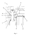
- les
figures 1 et2 sont des vues en coupe d'un appareil électrique selon l'invention ; - la
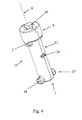
figure 3 montre un verrou ainsi qu'une rondelle formant un élément tampon ; - la
figure 4 montre un verrou ; - les
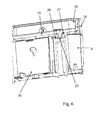
figures 5 et6 sont des vues en coupe d'un appareil selon l'invention, où la manette de l'interrupteur a été enlevée ; - la
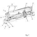
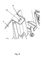
figure 7 montre, en coupe, un appareil électrique selon l'invention du type interrupteur encastré ; - la
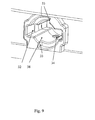
figure 8 montre un détail de l'élément de montage et lafigure 9 montre la partie correspondante au niveau du couvercle, et - la
figure 10 illustre le fonctionnement de l'élément tampon.
- the
figures 1 and2 are sectional views of an electrical apparatus according to the invention; - the
figure 3 shows a lock and a washer forming a buffer element; - the
figure 4 shows a lock; - the
figures 5 and6 are sectional views of an apparatus according to the invention, wherein the switch handle has been removed; - the
figure 7 shows, in section, an electrical appliance according to the invention of the recessed switch type; - the
figure 8 shows a detail of the mounting element and thefigure 9 shows the corresponding part at the lid, and - the
figure 10 illustrates the operation of the buffer element.
L'invention a donc pour objet un appareil électrique 1, tel que, par exemple, interrupteur et/ou socle de connexion pour fiche électrique, destiné à être monté en saillie contre ou encastré dans une paroi, comprenant au moins un bloc fonctionnel électrique, un élément de montage 4 pour le montage à la paroi et la fixation dudit au moins bloc fonctionnel, tel qu'une boîte pour un montage en saillie ou un support plat pour un montage encastré, et un couvercle 5, définissant un plan principal 12, formant la façade de l'appareil électrique 1 visible après installation, et placé sur l'élément de montage 4. Dans certains cas, le couvercle 5 peut permettre à l'utilisateur d'interagir avec le au moins un bloc fonctionnel, comme lui permettre de relier une fiche électrique à un bloc électrique du type socle ou de commuter un bloc fonctionnel du type interrupteur. Le couvercle 5 peut alternativement fermer entièrement l'élément de montage 4 en rendant inaccessible le au moins un bloc fonctionnel.The subject of the invention is therefore an electrical appliance 1, such as, for example, a switch and / or connection socket for electrical plug, intended to be mounted projecting against or embedded in a wall, comprising at least one electrical functional block, a
Dans le cas d'une fonction d'interrupteur, le au moins un bloc fonctionnel est alors commandé par au moins une manette 28 présente dans le couvercle 5 et sur laquelle un utilisateur peut agir, le bloc fonctionnel pouvant être monostable ou bistable, ladite au moins une manette 28 étant généralement amovible.In the case of a switch function, the at least one functional block is then controlled by at least one
Le couvercle 5 peut aussi remplir une fonction d'affichage, en intégrant par exemple un écran. Comme il sera décrit plus loin, le couvercle 5 peut aussi prendre la forme d'une plaque 20 dans laquelle au moins un enjoliveur 21 est monté.The
Lorsque l'appareil électrique 1 est mis en place, le plan principal 12 est parallèle à la paroi.When the electrical appliance 1 is put in place, the
Selon l'invention, l'appareil électrique 1 comprend un joint d'interface 26 entre l'élément de montage 4 et le couvercle 5, ainsi qu'au moins un moyen de fixation 6 de couvercle 5, apte à fixer ledit couvercle 5 directement à l'élément de montage 4 et comprenant au moins un élément tampon 3, déformé lorsque le couvercle 5 est fixé à l'élément de montage 4 et apte à compenser au moins partiellement, par une réduction progressive de sa propre déformation dans le temps, le vieillissement qui a lieu dans le joint d'interface 26, ce vieillissement étant notamment dû à une relaxation de contrainte dans le joint d'interface 26, généralement fait en polymère. Il est aussi envisageable que le au moins un moyen de fixation 6 soit masqué par une manette 28 d'interrupteur, ce qui permet d'avoir un montage discret.According to the invention, the electrical apparatus 1 comprises an
Le joint d'interface 26 permet de garantir l'étanchéité de la zone de contact entre l'élément de montage 4 et le couvercle 5, et il est donc comprimé dès lors que le couvercle 5 est correctement monté contre l'élément de montage 4, au moins tout de suite après le premier montage du couvercle 5. Le au moins un moyen de fixation 6 fixe directement le couvercle 5 à l'élément de montage 4, suffisamment proche pour que le joint d'interface 26 soit normalement comprimé. Il peut, par exemple, s'agir d'une simple vis. Un mode de réalisation avantageux du moyen de fixation 6 est décrit plus loin.The
Dès lors que l'appareil électrique 1 est placé dans un environnement humide, il est nécessaire de garantir l'étanchéité au niveau du joint d'interface 26, et donc d'en garantir en permanence une bonne compression, et donc un état de contrainte associée élevé, généralement obtenu en lui imposant une déformation par compression conséquente. Il est donc important que le au moins un moyen de fixation 6 fixe le couvercle 5 à l'élément de montage 4 avec une force suffisante pour comprimer en permanence le joint d'interface 26 qui se trouve entre eux. Le moyen de fixation 6 exerce donc sur le couvercle 5 une force suffisante pour que le joint d'interface 26 soit comprimé, au moins après l'installation. Or, classiquement, le couvercle 5, une fois installé, reste dans sa position suffisamment proche de l'élément de montage 4 pour que le moyen de fixation 6 soit comprimé, mais n'est pas resserré après l'installation. La déformation imposée au joint d'interface 26 est donc constante.As soon as the electrical apparatus 1 is placed in a humid environment, it is necessary to guarantee the seal at the
Néanmoins, le joint d'interface 26 est sujet au vieillissement, notamment par la relaxation de contraintes, qui consiste essentiellement en une diminution progressive de la force qu'oppose le joint d'interface 26 à sa propre déformation, cette dernière résultant en effet du maintien en position du couvercle 5 contre l'élément de montage 4, sous l'action du au moins un moyen de fixation 6. Le vieillissement a donc pour effet de réduire les capacités du joint d'interface 26, et donc aussi l'étanchéité qu'il permet d'obtenir.Nevertheless, the
L'élément tampon 3 a ainsi comme effet de compenser progressivement dans le temps ce vieillissement, et plus particulièrement la relaxation de contraintes, en ralentissant la diminution de la pression exercée sur le joint d'interface 26, entre le couvercle 5 et l'élément de montage 4. Pour ce faire, c'est la déformation imposée au joint d'interface 26 qui est progressivement augmentée. En l'absence d'un tel élément tampon 3, c'est essentiellement la déformation du joint d'interface 26 que le au moins un moyen de fixation 6 maintient sensiblement constante, ce qui conduit à la relaxation de contraintes décrite ci-dessus. Comme il est décrit ci-dessous, l'élément tampon 3 réduit progressivement dans le temps l'espace disponible pour le joint d'interface 26, à mesure que le joint d'interface 26 oppose une moindre résistance à sa déformation.The
Les
Les déformations de compression, d'une part, de l'élément tampon 3, et, d'autre part, du joint d'interface 26 se compensent, alors que les forces qu'opposent ces éléments à leur propre déformation par compression sont nécessairement les mêmes, ces deux éléments étant en effet montés mécaniquement en série l'un de l'autre dans un encombrement sensiblement constant dans le temps. Ainsi, à partir de la configuration initiale de la
Cette déformation par compression de plus grande amplitude du joint d'interface 26 se traduit par une augmentation de la force qu'oppose le joint d'interface 26 à sa déformation, se qui amène à une meilleure étanchéité. Les déformations et contraintes successives évoluent donc dans le temps de façon complémentaire : compte tenu du montage en série dans un logement de dimensions comparativement fixes, le joint d'interface 26 et l'élément tampon 3 sont donc en permanence dans des états de déformation qui, d'une part, sont complémentaires, dans le sens où l'augmentation de la déformation de l'un s'accompagnant de la diminution de la déformation de l'autre, et, d'autre part, correspondent à une égalité des forces que ces deux composants opposent dans leur état de déformation respectif. Cela permet de ralentir la réduction de la force associée à une déformation constante du joint d'interface 26.This compression deformation of greater amplitude of the
L'élément tampon 3 a donc pour effet de réduire progressivement dans le temps l'espace disponible pour le joint d'interface 26. Cette réduction tend ainsi à compenser la diminution de la pression que subit le joint d'interface 26.The
Selon une caractéristique additionnelle possible, qui permet notamment d'avoir un couvercle 5 en partie standardisé pour différents types d'appareil électrique 1, le couvercle 5 comprend, d'une part, une plaque 20 présentant au moins une ouverture 31, et, d'autre part, au moins un enjoliveur 21 compatible avec le au moins un bloc fonctionnel et placé dans ladite au moins une ouverture 31 ainsi qu'au moins un joint interne 27 installé entre ladite plaque 20 et ledit au moins un enjoliveur 21, le moyen de fixation 6 agissant sur le au moins un enjoliveur 21 de sorte que la plaque 20 est maintenue entre ledit au moins un enjoliveur 21 et l'élément de montage 4, l'élément tampon 3 étant apte, en outre, à compenser, par une réduction progressive de sa déformation, le vieillissement qui a lieu dans le au moins un joint interne 27, en particulier la relaxation de contraintes. La plaque 20 peut donc être standard, alors que l'enjoliveur 21 est propre au bloc fonctionnel. L'enjoliveur 21 peut être, par exemple, un enjoliveur 21 comprenant un puits 29 pour fiche électrique ou comprenant une manette 28 d'interrupteur et sa base 30. La compensation du vieillissement dans le au moins un joint interne 27 est la même que celle décrite pour le joint d'interface 26.According to an additional possible feature, which allows in particular to have a
Comme le couvercle 5 est ainsi en au moins deux parties, à savoir la plaque 20 et au moins un enjoliveur 21, au moins un joint interne 27 doit être monté dans le couvercle 5 afin de garantir l'étanchéité du couvercle 5 lui-même. Préférentiellement, comme le joint d'interface 26, le joint interne 27 se présente sous la forme d'un profilé de matière s'étendant le long d'un contour fermé, placé autour de l'ouverture 31, tel qu'un joint torique ou un joint à lèvre. Le au moins un joint interne 27 peut être obtenu par surmoulage sur la plaque 20, voire l'enjoliveur 21, ou prendre la forme d'une pièce indépendante, monté dans le couvercle 5. Comme le au moins un moyen de fixation 6 agit sur l'enjoliveur 21 et que la plaque 20 est prise entre l'élément de montage 4 et l'enjoliveur 21, le vieillissement du joint interne 27, placé entre l'enjoliveur et la plaque 20, est, au même titre que pour le joint d'interface, entre la plaque 20 et l'élément de montage 4, compensé par l'élément tampon 3.As the
Dans certains modes de réalisations particuliers, l'appareil électrique 1 présente une pluralité de blocs fonctionnels, éventuellement différents, un seul couvercle 5, comprenant une seule plaque 20 et une pluralité d'enjoliveur 21, chaque enjoliveur 21 correspondant à un bloc fonctionnel, chaque enjoliveur 21 étant maintenu par au moins deux moyens de fixation 6. Dans ces réalisations, si l'appareil électrique 1 est multiposte, le couvercle 5 présente plusieurs enjoliveurs 21 et donc autant d'ouvertures 31 et de joints internes 27 garantissant l'étanchéité entre la plaque 20 et l'enjoliveur 21. Dans ce cas, il est particulièrement intéressant de réaliser les joints internes 27 d'un seul tenant.In certain particular embodiments, the electrical apparatus 1 has a plurality of functional blocks, possibly different, a
Selon une caractéristique additionnelle possible, le au moins un moyen de fixation 6 de couvercle 5 est apte, d'une part, dans une position dite verrouillée d'un verrou 7 que comprend le au moins un moyen de fixation 6, à maintenir le couvercle 5 directement par rapport à l'élément de montage 4, et, d'autre part, dans une position dite libre dudit verrou 7, à ne pas maintenir le couvercle 5 par rapport à l'élément de montage 4, le passage de la position verrouillée à la position libre se faisant par une rotation de moins d'un tour dudit verrou 7 autour d'un axe 8 sensiblement perpendiculaire au plan principal 12, notamment d'un quart de tour, ce qui permet de rendre le montage du couvercle 5 sur l'élément de montage 4 particulièrement ergonomique.According to an additional possible feature, the at least one cover fixing means 6 is able, on the one hand, in a so-called locked position of a
Préférentiellement, le passage de la position verrouillée à la position libre se fait sans translation parallèle à l'axe 8, ce qui permet à l'installateur de ne pas assimiler ce mouvement de verrouillage ou déverrouillage à un mouvement de fixation d'une vis munie d'un filetage.Preferably, the transition from the locked position to the free position is done without translation parallel to the
En position de verrouillage, une extrémité du verrou 7 est en appui sur le couvercle 5, préférentiellement sur la plaque 20, notamment sur la base 30 pour un interrupteur, l'autre extrémité venant en appui dans l'élément de montage 4, ce qui permet donc à l'au moins un moyen de fixation 6 de maintenir directement le couvercle 5 à l'élément de montage 4.In the locking position, one end of the
Selon une caractéristique additionnelle possible, le verrou 7 prend essentiellement la forme d'une tige 10, présentant un corps 11 ainsi que, d'une part, une tête 9 pour son actionnement, ledit corps 11 étant plus fin que ladite tête 9, et, d'autre part, une pointe 17 présentant au moins une aile 18, faisant saillie par rapport au corps 11 de la tige 10, ce qui permet de retenir le verrou 7 par rapport à l'élément de montage 4 et par rapport au couvercle 5, d'une part, grâce à ladite au moins une aile 18 en appui dans l'élément de montage 4, et, d'autre part, grâce à la tête 9 en appui dans le couvercle 5. Le fait de passer de la position de verrouillage à la position libre a pour effet de dégager de sa butée la tête 9 et/ou la au moins une aile 18 de la pointe 17.According to an additional possible feature, the
Selon une caractéristique additionnelle possible, qui permet à un installateur, muni d'outils classiques, de réaliser l'installation, des rainures 19 pour l'actionnement au moyen d'un outil plat du type tournevis sont prévues sur le verrou 7, notamment sur la ou une tête 9 d'une tige 10 qui forme le verrou 7. C'est grâce à ces rainures que l'installateur peut créer le mouvement de rotation permettant de passer de la position verrouillée à la position libre et inversement.According to an additional possible feature, which allows an installer, equipped with conventional tools, to perform the installation,
Selon une caractéristique additionnelle possible, qui permet de maintenir le couvercle 5 à l'aide du au moins un verrou 7, dans une position dans laquelle le joint d'interface 26 et le au moins un éventuel joint interne 27 sont comprimés, le au moins un moyen de fixation 6 comprend au moins une surface d'appui de verrouillage 13 pour le verrou 7, contre laquelle ce dernier peut s'appuyer pour maintenir le couvercle 5 à l'élément de montage 4 dans la position verrouillée, notamment une surface d'appui de verrouillage 13 aménagée sur l'élément tampon 3. Le couvercle 5 est donc maintenu contre l'élément de montage 4 par le verrou 7, en appui, pour sa tête 9, dans le couvercle 5, et, pour sa pointe 17, notamment l'aile 18, sur la surface d'appui de verrouillage 13. Lorsque le verrou 7 est en appui contre la surface d'appui de verrouillage 13, le couvercle 5 est maintenu suffisamment proche de l'élément de montage 4 pour que l'élément tampon 3 et 1 joint d'interface 26 soient comprimés, de façon complémentaire comme décrit plus haut, ainsi que, de la même façon, l'au moins un éventuel joint interne 27.According to a possible additional feature, which makes it possible to hold the
Selon une autre caractéristique additionnelle possible, facilitant la mise en place du couvercle 5, le au moins un moyen de fixation 6 comprend au moins une surface de guidage 14 dans le prolongement de la au moins une surface d'appui de verrouillage 13, sur laquelle le verrou 7 peut circuler jusqu'à la au moins une surface d'appui de verrouillage 13 en rapprochant le couvercle 5 de l'élément de montage 4. Ainsi, pour passer de la position libre à la position verrouillée, l'aile circule sur la surface de guidage 14, qui a une forme hélicoïdale, ce qui a pour effet de rapprocher le couvercle 5 de l'élément de montage 4, et donc de comprimer l'élément tampon 3 et le joint d'interface 26, ainsi que l'au moins un éventuel joint interne 27. Il n'est donc pas nécessaire de presser le couvercle 5 contre l'élément de montage 4 avant de passer de la position libre à la position de verrouillage, puisque la circulation sur la surface de guidage 14 a pour effet de rapprocher le couvercle 5 de l'élément de montage 4. Le montage du couvercle est donc plus facile pour l'installateur.According to another additional feature possible, facilitating the installation of the
La surface de guidage 14 prend donc une forme d'hélice qui transforme le mouvement de rotation du verrou 7 en un mouvement de translation. Lorsque le verrou 7 est en position verrouillée, l'aile 18 est en appui contre la surface d'appui de verrouillage 13. Un mouvement inverse doit être effectué pour passer de la position de verrouillage à la position libre. L'aile 18 quitte alors la surface d'appui de verrouillage 13 et circule sur la surface de guidage 14, permettant progressivement à la tête 9 de s'éloigner de l'élément de montage 4 est donc au couvercle 5, pris entre eux, de s'en écarter aussi. Comme il sera décrit plus loin, l'aile 18 aboutit ensuite au niveau d'un premier dégagement 16 aménagé dans l'élément de montage 4, ce qui permet d'en détacher complètement le couvercle 5, puisque l'aile 18 n'est alors plus retenue contre l'élément de montage 4 mais peut librement circuler le premier dégagement 16.The
Selon une caractéristique additionnelle possible, l'élément tampon 3 porte la au moins une surface d'appui de verrouillage 13 ainsi que la au moins une surface de guidage 14 et prend la forme d'une pièce rapportée 15, placée au sein de l'élément de montage 4, et déformée lorsque le verrou 7 se trouve dans la position de verrouillage. Le recours à une pièce rapportée permet de faciliter la fabrication de l'élément de tampon 4. Selon une caractéristique additionnelle possible, la pièce rapportée 15 est une rondelle métallique, ce qui garantit une plus longue durée de la compensation du vieillissement. Cette rondelle métallique est placée dans l'élément de montage 4, et présente une découpe lui permettant d'être traversée par la pointe 17 du verrou 7, notamment une découpe sous la forme d'un trou oblong dans le cas où la pointe 17 présente deux ailes 18.According to an additional possible feature, the
Comme le montre la
En outre, comme le montre encore la
L'orifice de passage 38 et le deuxième dégagement 32 sont aménagés au sein d'un plot creux 24 du couvercle 5 accueilli dans un passage 37 dans la plaque 20 ou une plaque 20 que comprend le couvercle 5, permettant ainsi de dégager le au moins un verrou 7 du couvercle 5 en y faisant passer la pointe 17. Si le au moins un deuxième dégagement 32 du couvercle 5 est situé en vis-à-vis du premier dégagement 16 de l'élément de montage 4 lorsque le couvercle 5 est monté sur ledit élément de montage 4, le verrou 7 peut, dans sa position libre, être dégagé à la fois du couvercle 5 et de l'élément de montage 4.The
Dans des modes de réalisation particulièrement avantageux, la pointe 17 est munie de deux ailes 18 en saillie par rapport au corps 11 de la tige 10 et diamétralement opposées, la position libre et la position verrouillée étant séparées par une rotation d'un quart de tour. Les divers autres éléments du moyen de fixation 6 ainsi que l'appareil 1 lui-même sont adaptés à ce nombre d'ailes 18 : l'orifice de passage 38 est muni de deux deuxièmes dégagements 32 diamétralement opposés, le premier orifice 23 est muni de deux premiers dégagements 16 diamétralement opposés permettant ainsi de passer de la position libre à la position verrouillée indépendamment du sens de rotation du au moins un verrou 7, le moyen de fixation 6 présente deux surfaces d'appui de verrouillage 13 diamétralement opposées ainsi que deux surfaces de guidage 14 adaptées, la pièce rapportée 15 présentant un trou oblong pour le passage simultané des deux ailes 18. Bien entendu, un nombre différent d'ailes 18 et des écarts angulaires différents sont envisageables.In particularly advantageous embodiments, the
Selon une caractéristique additionnelle possible de l'appareil électrique 1, le au moins un moyen de fixation 6 présente au moins un ergot 34 et au moins un logement 35 pour ledit ergot 34, aménagés de sorte à limiter la translation du verrou 7, par rapport au couvercle 5, parallèlement à l'axe 8, notamment un logement 35 sous forme de rainure circonférentielle, l'ergot 34 et le logement 35 étant, pour l'un, aménagé au niveau du verrou 7, et, pour l'autre, au niveau du couvercle 5, notamment au niveau de l'enjoliveur 21 ou d'un enjoliveur 21 que comprend le couvercle 5. Cela permet de maintenir au moins légèrement le verrou 7 dans le couvercle 5, dans la direction de l'axe 8, et garantit donc l'imperdabilité du verrou 7.According to an additional possible characteristic of the electrical apparatus 1, the at least one fastening means 6 has at least one
Préférentiellement, le au moins un ergot 34 et le au moins un logement 35 sont aménagés de sorte à limiter, en outre, la rotation du verrou 7 autour de l'axe 8 sensiblement à partir de la position libre. Les
L'imperdabilité du verrou 7 est donc garantie, puisqu'il est maintenu dans le couvercle 5. En outre, l'installateur sait que lorsque le verrou 7 se stabilise dans une position angulaire, cette dernière correspond à la position libre. Ainsi, le verrou 7 peut être mis dans la position libre avant de procéder au montage et maintenu jusqu'à procéder à la fixation du couvercle 5 sur l'élément de montage 4 par rotation du verrou 7 entre la position libre et la position de verrouillage. La
Selon une caractéristique additionnelle possible, le au moins un moyen de fixation 6 présente, d'une part, au moins un élément de butée 2, aménagé au niveau du verrou 7, et notamment sous la tête 9 ou une tête 9 d'une tige 10 que comprend le verrou 7, et, d'autre part, au moins une face de butée 33, aménagée dans le couvercle 5 et au contact de laquelle vient le au moins un élément de butée 2 lorsque le verrou 7 se trouve dans la position de verrouillage ou lorsqu'il subit un mouvement de rotation de plus grande amplitude que celle nécessaire lors du passage de la position libre à la position de verrouillage, ce qui permet d'éviter que l'installateur ne manipule le verrou 7 comme une vis tournant dans le vide et ait ainsi l'impression que l'appareil électrique 1 est défectueux, mais aussi d'éviter la dégradation de l'appareil électrique 1 si l'installateur fait subir au verrou 7 un mouvement trop ample ou un couple trop important.According to an additional possible feature, the at least one attachment means 6 has, on the one hand, at least one
Selon une caractéristique additionnelle possible, le au moins un enjoliveur 21 est maintenu par deux moyens de fixation 6, disposés à proximité de deux bords opposés dudit enjoliveur 21 et décalés l'un par rapport à l'autre, l'appareil électrique 1 comprenant en outre, deux moyens d'accrochage 22 de l'enjoliveur 21 à la plaque 20, disposés symétriquement aux deux verrous 7, et consistant essentiellement chacun en une patte munie de crochets et s'étendant à partir de l'enjoliveur 21, destinée à venir s'accrocher dans un trou prévu dans la plaque 20, permettant ainsi d'avoir une bonne tenue mécanique et une bonne fixation du couvercle 5 sur l'élément de montage 4 tout en limitant le nombre d'opérations à réaliser par l'installateur ainsi que le prix d'un tel appareil électrique 1.According to an additional possible feature, the at least one
Selon une caractéristique additionnelle possible, l'appareil électrique 1 comprend, en outre, un joint arrière 25, au niveau de la face de l'élément de montage 4 destinée à être en contact avec la paroi, le joint d'interface 26 et le au moins un joint interne 27 étant réalisés d'un seul tenant, notamment par surmoulage sur le couvercle 5 ou sur la ou une plaque 20 que comprend le couvercle 5, permettant ainsi de garantir une étanchéité supplémentaire entre le mur et l'appareil électrique 1.According to an additional possible feature, the electrical apparatus 1 further comprises a
Dans un mode de réalisation particulier, l'élément de montage 4 consiste en une boîte pour le montage en saillie de l'appareil électrique 1, présentant une cavité d'accueil 39 pour le au moins un bloc fonctionnel, le verrou 7 aboutissant, pour une de ses extrémités, notamment la ou une pointe 17, au sein de l'élément de montage 4 dans une zone ne communicant pas avec la cavité d'accueil 39, la boîte présentant notamment, en outre, des crochets pour l'encliquetage du au moins un bloc fonctionnel. Le fait que le verrou 7 aboutit hors de la cavité d'accueil 39 évite que les différents orifices aménagés pour l'accueillir ne permettent d'amener de l'eau ou d'autres particules trop proches de l'appareil électrique 1.In a particular embodiment, the mounting
Bien entendu, l'invention n'est pas limitée au mode de réalisation décrit et représenté aux dessins annexés. Des modifications restent possibles, notamment du point de vue de la constitution des divers éléments, par combinaison différente des caractéristiques décrites, ou par substitution d'équivalents techniques, sans sortir pour autant du domaine de protection de l'invention.Of course, the invention is not limited to the embodiment described and shown in the accompanying drawings. Modifications are possible, particularly from the point of view of the constitution of the various elements, by different combination of the characteristics described, or by substitution of technical equivalents, without departing from the scope of protection of the invention.
Claims (16)
- Electrical appliance (1) such as, for example, a switch and/or a socket front for an electrical plug, which is intended to be wall-mounted on or flushmounted in a wall, comprising at least one electrical functional unit, a mounting element (4) for mounting to the wall and fixing the said at least one functional unit, such as a box wall mounting or a flat support for flush mounting, and a cover (5), defining a main plane (12) forming the facade of the electrical appliance (1) that is visible after installation and placed on the mounting element (4), the said electrical appliance (1) comprising an interface seal (26) between the mounting element (4) and the cover (5), and at least one cover (5) fixing means (6) able to fix the said cover (5) directly to the mounting element (4) and comprising at least one buffer element (3) that becomes deformed when the cover (5) is fixed to the mounting element (4) and able at least partially, through a progressive reduction of its own deformation over time, to compensate for the ageing that occurs in the interface seal (26), characterized in that the at least one fixing means (6) comprises at least one guide surface (14) on which a lock (7) that the said fixing means (6) comprises can run in order to pass from a free position to a locked position while bringing the cover (5) closer to the mounting element (4).
- Electrical appliance (1) according to Claim 1, characterized in that the cover (5) comprises, on the one hand, a plate (20) having at least one opening (31), and, on the other hand, at least one trim (21) compatible with the at least one functional unit and placed in the said at least one opening (31) and at least one internal seal (27) installed between the said plate (20) and the said at least one trim (21), the fixing means (6) acting on the at least one trim (21) in such a way that the plate (20) is held between the said at least one trim (21) and the mounting element (4), the buffer element (3) being further able, through a progressive reduction in its deformation, to compensate for the ageing that occurs in the at least one internal seal (27).
- Electrical appliance (1) according to either one of Claims 1 and 2, characterized in that the at least one cover (5) fixing means (6) is able, on the one hand, in a position referred to as the locked position of a lock (7) that the at least one fixing means (6) comprises, to hold the cover (5) directly with respect to the mounting element (4) and, on the other hand, in a position referred to as the free position of the said lock (7), not to hold the cover (5) with respect to the mounting element (4), passage from the locked position to the free position taking place via a rotation of the said lock (7) by under one turn about an axis (8) substantially perpendicular to the main plane (12).
- Electrical appliance (1) according to Claim 3, characterized in that the lock (7) essentially adopts the form of a shank (10) having a body (11) and, on the one hand, a head (9) for actuating it, the said body (11) being more slender than the said head (9) and, on the other hand, a tip (17) having at least one wing (18) projecting from the body (11) of the shank (10).
- Electrical appliance (1) according to either one of Claims 3 and 4, characterized in that the at least one fixing means (6) comprises at least one locking bearing surface (13) for the lock (7), against which surface this lock can bear in order to hold the cover (5) to the mounting element (4) in the locked position, notably a locking bearing surface (13) formed on the buffer element (3).
- Electrical appliance (1) according to Claim 5, characterized in that the at least one fixing means (6) comprises at least one guide surface (14) in the continuation of the at least one locking bearing surface (13), on which surface the lock (7) can run as far as the at least one locking bearing surface (13), while bringing the cover (5) closer to the mounting element (4).
- Electrical appliance (1) according to Claim 6, characterized in that the buffer element (3) bears the at least one locking bearing surface (13) and the at least one guide surface (14) and takes the form of an attached part (15) positioned within the mounting element (4) and deformed when the lock (7) is in the locking position.
- Electrical appliance (1) according to Claim 7, characterized in that the attached part (15) is a metal washer.
- Electrical appliance (1) according to any one of Claims 3 to 8, characterized in that the at least one fixing means (6) has at least one lug (34) and at least one housing (35) for the said lug (34), these being formed in such a way as to limit the translational movement of the lock (7) with respect to the cover (5) parallel to the axis (8), notably a housing (35) in the form of a circumferential groove, the lug (34) and the housing (35) being, one of them, formed at the lock (7) and the other at the cover (5), notably at the trim (21) or at a trim (21) that the cover (5) comprises.
- Electrical appliance (1) according to Claim 9, characterized in that the at least one lug (34) and the at least one housing (35) are formed in such a way as also to limit the rotation of the lock (7) about the axis (8) substantially from the free position.
- Electrical appliance (1) according to any one of Claims 3 to 10, characterized in that the at least one fixing means (6) has, on the one hand, at least one stop element (2) formed at the lock (7) and notably under the head (9) or a head (9) of a shank (10) that the lock (7) comprises and, on the other hand, at least one stop face (33), formed in one cover (5) and with which the at least one stop element (2) comes into contact when the lock (7) is in the locking position or when it undergoes a rotational movement of a greater amplitude than that needed when passing from the free position into the locking position.
- Electrical appliance (1) according to any one of Claims 3 to 11, characterized in that slots (19) for actuation by means of a flat tool of the screwdriver type are provided on the lock (7), notably on the or a head (9) of a shank (10) which forms the lock (7).
- Electrical appliance (1) according to any one of Claims 2 to 12, characterized in that the at least one trim (21) is held by two fixing means (6) arranged near two opposite edges of the said trim (21) and offset from one another, the electrical appliance (1) further comprising two catching means (22) for catching the trim (21) to the plate (20), these means being arranged symmetrically with respect to the two locks (7) and each essentially consisting of a tab provided with hooks and extending from the trim (21), which is intended to catch in a hole made in the plate (20).
- Electrical appliance (1) according to any one of Claims 1 to 13, characterized in that the electrical appliance (1) further comprises a rear seal (25), at that face of the mounting element (4) that is intended to be in contact with the wall, the interface seal (26) and the at least one internal seal (27) being produced as a single piece, notably by overmoulding on the cover (5) or on the or a plate (20) that the cover (5) comprises.
- Electrical appliance (1) according to any one of Claims 1 to 14, characterized in that the mounting element (4) consists of a box for wall-mounting the electrical appliance (1), having an accommodating cavity (39) to accommodate the at least one functional unit, the lock (7) reaching, at least in the case of one of its ends, notably the or a tip (17) thereof, into the mounting element (4) in a region that does not communicate with the accommodating cavity (39), the box notably also having hooks for the clip-fastening of the at least one functional unit.
- Electrical appliance (1) according to any one of Claims 1 to 15, characterized in that it has a plurality of functional units, possibly different ones, a single cover (5) comprising a single plate (20) and a plurality of trims (21), each trim (21) corresponding to one functional unit, each trim (21) being held by at least two fixing means (6).
Priority Applications (3)
| Application Number | Priority Date | Filing Date | Title |
|---|---|---|---|
| PT12305204T PT2632002E (en) | 2012-02-22 | 2012-02-22 | Sealed electrical appliance with buffer element |
| EP20120305204 EP2632002B1 (en) | 2012-02-22 | 2012-02-22 | Sealed electrical appliance with buffer element |
| ES12305204.5T ES2504119T3 (en) | 2012-02-22 | 2012-02-22 | Waterproof electrical device with buffer element |
Applications Claiming Priority (1)
| Application Number | Priority Date | Filing Date | Title |
|---|---|---|---|
| EP20120305204 EP2632002B1 (en) | 2012-02-22 | 2012-02-22 | Sealed electrical appliance with buffer element |
Publications (2)
| Publication Number | Publication Date |
|---|---|
| EP2632002A1 EP2632002A1 (en) | 2013-08-28 |
| EP2632002B1 true EP2632002B1 (en) | 2014-06-18 |
Family
ID=45851446
Family Applications (1)
| Application Number | Title | Priority Date | Filing Date |
|---|---|---|---|
| EP20120305204 Active EP2632002B1 (en) | 2012-02-22 | 2012-02-22 | Sealed electrical appliance with buffer element |
Country Status (3)
| Country | Link |
|---|---|
| EP (1) | EP2632002B1 (en) |
| ES (1) | ES2504119T3 (en) |
| PT (1) | PT2632002E (en) |
Families Citing this family (2)
| Publication number | Priority date | Publication date | Assignee | Title |
|---|---|---|---|---|
| DE102016014660A1 (en) * | 2016-12-09 | 2018-06-14 | Dürr Systems Ag | Closure device for attachment to a robot |
| IT202300011247A1 (en) * | 2023-06-01 | 2024-12-01 | Bticino Spa | ENCLOSURE FOR SURFACE MOUNTING OF AT LEAST ONE ELECTRICAL APPLIANCE ON A WALL |
Family Cites Families (4)
| Publication number | Priority date | Publication date | Assignee | Title |
|---|---|---|---|---|
| DE3309593A1 (en) | 1983-03-17 | 1984-09-20 | Brown, Boveri & Cie Ag, 6800 Mannheim | ELECTRIC SWITCH OR BUTTON WITH TWO LARGE AREA ROCKERS |
| DE9110236U1 (en) * | 1991-08-19 | 1991-12-19 | Hans-Joachim Bernstein Compact-Gehäuse GmbH, 4955 Hille | Terminal housing |
| FR2823905B1 (en) | 2001-04-23 | 2004-01-30 | Legrand Sa | SEALED ELECTRICAL EQUIPMENT CONTROL DEVICE |
| DE10234727A1 (en) | 2002-07-30 | 2003-08-07 | Siemens Ag | Switch with manual operating element, has sealing foil arranged between suspension yoke and covering frame with aperture smaller than that in covering frame |
-
2012
- 2012-02-22 EP EP20120305204 patent/EP2632002B1/en active Active
- 2012-02-22 ES ES12305204.5T patent/ES2504119T3/en active Active
- 2012-02-22 PT PT12305204T patent/PT2632002E/en unknown
Also Published As
| Publication number | Publication date |
|---|---|
| PT2632002E (en) | 2014-09-22 |
| ES2504119T3 (en) | 2014-10-08 |
| EP2632002A1 (en) | 2013-08-28 |
Similar Documents
| Publication | Publication Date | Title |
|---|---|---|
| FR2902394A1 (en) | DEVICE FOR FASTENING A WIPER BLADE ON AN ARM | |
| EP0340161A1 (en) | Elastic hinge for spectacle frame | |
| FR3087218A1 (en) | HANDLE ASSEMBLY FOR WINDOW OR DOOR OPENING ELEMENTS | |
| FR2924080A1 (en) | PLATFORM FOR CONNECTING A WIPER BLADE FOR A MOTOR VEHICLE | |
| EP1087075B1 (en) | Permanent anchoring device | |
| EP2632002B1 (en) | Sealed electrical appliance with buffer element | |
| EP1182522A1 (en) | Assembling device | |
| FR3060101B1 (en) | DEVICE FOR CONNECTING LUMINAIRE | |
| FR2893969A1 (en) | Opening element e.g. door, locking device, has body comprising head terminated by elastic retaining tab which elastically cooperates with finger of tentative spacing device when opening element is in closed position | |
| FR2794787A1 (en) | RETURN DEVICE | |
| EP2632001B1 (en) | Electrical appliance with lid attached in the mounting member | |
| FR2907080A1 (en) | Windscreen wiper arm fixing device for motor vehicle, has blocking unit blocking male unit in female cavity, and male unit comes in contact with windscreen wiper arm, where blocking unit has leaf spring projection in cavity at relaxed state | |
| FR2897908A1 (en) | FIXING ARRANGEMENT | |
| FR2799805A1 (en) | Wall anchor for safety fitment such as ladder or platform has spacer bush under head to receive coupling member on fitment | |
| EP3554872B1 (en) | Vehicle sliding door | |
| FR3057896A1 (en) | MOUNTING A FLUSH TYPE DOOR OPENING ORDER | |
| EP2909400A1 (en) | Bolt securing device for a motor vehicle door and motor vehicle comprising such a securing device | |
| EP2632004A1 (en) | Electrical appliance provided with an insert for attaching the lid | |
| EP2824785B1 (en) | Hinged assembly of a housing for electrical equipment and floor box including such an assembly | |
| FR2990010A1 (en) | BODY FOR ATTACHING AN ATTACHMENT TO A SUPPORT AND SUPPORT ON A STRUCTURE | |
| FR3040946A1 (en) | ADAPTER FOR AUTOMOTIVE VEHICLE WIPER ARMS | |
| EP4534781A1 (en) | Control device for a locking fitting for a door or window-type joinery work | |
| FR3157696A1 (en) | Stem cap to ensure electrical busbar fixation and sealing | |
| FR2715428A1 (en) | Safety lock for electricity, gas telephone or water control boxes | |
| FR2808598A1 (en) | Temple pivot for spectacle frame has hinge with lugs receiving pivot pin held by insert with stops to prevent rotation |
Legal Events
| Date | Code | Title | Description |
|---|---|---|---|
| PUAI | Public reference made under article 153(3) epc to a published international application that has entered the european phase |
Free format text: ORIGINAL CODE: 0009012 |
|
| AK | Designated contracting states |
Kind code of ref document: A1 Designated state(s): AL AT BE BG CH CY CZ DE DK EE ES FI FR GB GR HR HU IE IS IT LI LT LU LV MC MK MT NL NO PL PT RO RS SE SI SK SM TR |
|
| AX | Request for extension of the european patent |
Extension state: BA ME |
|
| 17P | Request for examination filed |
Effective date: 20131107 |
|
| RBV | Designated contracting states (corrected) |
Designated state(s): AL AT BE BG CH CY CZ DE DK EE ES FI FR GB GR HR HU IE IS IT LI LT LU LV MC MK MT NL NO PL PT RO RS SE SI SK SM TR |
|
| GRAP | Despatch of communication of intention to grant a patent |
Free format text: ORIGINAL CODE: EPIDOSNIGR1 |
|
| RIC1 | Information provided on ipc code assigned before grant |
Ipc: H02G 3/08 20060101AFI20131210BHEP Ipc: H02G 3/14 20060101ALI20131210BHEP |
|
| INTG | Intention to grant announced |
Effective date: 20140108 |
|
| GRAS | Grant fee paid |
Free format text: ORIGINAL CODE: EPIDOSNIGR3 |
|
| GRAA | (expected) grant |
Free format text: ORIGINAL CODE: 0009210 |
|
| AK | Designated contracting states |
Kind code of ref document: B1 Designated state(s): AL AT BE BG CH CY CZ DE DK EE ES FI FR GB GR HR HU IE IS IT LI LT LU LV MC MK MT NL NO PL PT RO RS SE SI SK SM TR |
|
| REG | Reference to a national code |
Ref country code: GB Ref legal event code: FG4D Free format text: NOT ENGLISH |
|
| REG | Reference to a national code |
Ref country code: CH Ref legal event code: EP |
|
| REG | Reference to a national code |
Ref country code: AT Ref legal event code: REF Ref document number: 673839 Country of ref document: AT Kind code of ref document: T Effective date: 20140715 |
|
| REG | Reference to a national code |
Ref country code: IE Ref legal event code: FG4D Free format text: LANGUAGE OF EP DOCUMENT: FRENCH |
|
| REG | Reference to a national code |
Ref country code: DE Ref legal event code: R096 Ref document number: 602012002155 Country of ref document: DE Effective date: 20140731 |
|
| REG | Reference to a national code |
Ref country code: CH Ref legal event code: NV Representative=s name: DR. GRAF AND PARTNER AG INTELLECTUAL PROPERTY, CH |
|
| REG | Reference to a national code |
Ref country code: PT Ref legal event code: SC4A Free format text: AVAILABILITY OF NATIONAL TRANSLATION Effective date: 20140915 |
|
| REG | Reference to a national code |
Ref country code: ES Ref legal event code: FG2A Ref document number: 2504119 Country of ref document: ES Kind code of ref document: T3 Effective date: 20141008 |
|
| PG25 | Lapsed in a contracting state [announced via postgrant information from national office to epo] |
Ref country code: NO Free format text: LAPSE BECAUSE OF FAILURE TO SUBMIT A TRANSLATION OF THE DESCRIPTION OR TO PAY THE FEE WITHIN THE PRESCRIBED TIME-LIMIT Effective date: 20140918 Ref country code: FI Free format text: LAPSE BECAUSE OF FAILURE TO SUBMIT A TRANSLATION OF THE DESCRIPTION OR TO PAY THE FEE WITHIN THE PRESCRIBED TIME-LIMIT Effective date: 20140618 Ref country code: CY Free format text: LAPSE BECAUSE OF FAILURE TO SUBMIT A TRANSLATION OF THE DESCRIPTION OR TO PAY THE FEE WITHIN THE PRESCRIBED TIME-LIMIT Effective date: 20140618 Ref country code: LT Free format text: LAPSE BECAUSE OF FAILURE TO SUBMIT A TRANSLATION OF THE DESCRIPTION OR TO PAY THE FEE WITHIN THE PRESCRIBED TIME-LIMIT Effective date: 20140618 Ref country code: GR Free format text: LAPSE BECAUSE OF FAILURE TO SUBMIT A TRANSLATION OF THE DESCRIPTION OR TO PAY THE FEE WITHIN THE PRESCRIBED TIME-LIMIT Effective date: 20140919 |
|
| REG | Reference to a national code |
Ref country code: NL Ref legal event code: VDEP Effective date: 20140618 |
|
| REG | Reference to a national code |
Ref country code: AT Ref legal event code: MK05 Ref document number: 673839 Country of ref document: AT Kind code of ref document: T Effective date: 20140618 |
|
| REG | Reference to a national code |
Ref country code: LT Ref legal event code: MG4D |
|
| PG25 | Lapsed in a contracting state [announced via postgrant information from national office to epo] |
Ref country code: HR Free format text: LAPSE BECAUSE OF FAILURE TO SUBMIT A TRANSLATION OF THE DESCRIPTION OR TO PAY THE FEE WITHIN THE PRESCRIBED TIME-LIMIT Effective date: 20140618 Ref country code: RS Free format text: LAPSE BECAUSE OF FAILURE TO SUBMIT A TRANSLATION OF THE DESCRIPTION OR TO PAY THE FEE WITHIN THE PRESCRIBED TIME-LIMIT Effective date: 20140618 Ref country code: SE Free format text: LAPSE BECAUSE OF FAILURE TO SUBMIT A TRANSLATION OF THE DESCRIPTION OR TO PAY THE FEE WITHIN THE PRESCRIBED TIME-LIMIT Effective date: 20140618 Ref country code: LV Free format text: LAPSE BECAUSE OF FAILURE TO SUBMIT A TRANSLATION OF THE DESCRIPTION OR TO PAY THE FEE WITHIN THE PRESCRIBED TIME-LIMIT Effective date: 20140618 |
|
| PG25 | Lapsed in a contracting state [announced via postgrant information from national office to epo] |
Ref country code: EE Free format text: LAPSE BECAUSE OF FAILURE TO SUBMIT A TRANSLATION OF THE DESCRIPTION OR TO PAY THE FEE WITHIN THE PRESCRIBED TIME-LIMIT Effective date: 20140618 Ref country code: SK Free format text: LAPSE BECAUSE OF FAILURE TO SUBMIT A TRANSLATION OF THE DESCRIPTION OR TO PAY THE FEE WITHIN THE PRESCRIBED TIME-LIMIT Effective date: 20140618 Ref country code: CZ Free format text: LAPSE BECAUSE OF FAILURE TO SUBMIT A TRANSLATION OF THE DESCRIPTION OR TO PAY THE FEE WITHIN THE PRESCRIBED TIME-LIMIT Effective date: 20140618 Ref country code: RO Free format text: LAPSE BECAUSE OF FAILURE TO SUBMIT A TRANSLATION OF THE DESCRIPTION OR TO PAY THE FEE WITHIN THE PRESCRIBED TIME-LIMIT Effective date: 20140618 |
|
| PG25 | Lapsed in a contracting state [announced via postgrant information from national office to epo] |
Ref country code: AT Free format text: LAPSE BECAUSE OF FAILURE TO SUBMIT A TRANSLATION OF THE DESCRIPTION OR TO PAY THE FEE WITHIN THE PRESCRIBED TIME-LIMIT Effective date: 20140618 Ref country code: NL Free format text: LAPSE BECAUSE OF FAILURE TO SUBMIT A TRANSLATION OF THE DESCRIPTION OR TO PAY THE FEE WITHIN THE PRESCRIBED TIME-LIMIT Effective date: 20140618 Ref country code: PL Free format text: LAPSE BECAUSE OF FAILURE TO SUBMIT A TRANSLATION OF THE DESCRIPTION OR TO PAY THE FEE WITHIN THE PRESCRIBED TIME-LIMIT Effective date: 20140618 Ref country code: IS Free format text: LAPSE BECAUSE OF FAILURE TO SUBMIT A TRANSLATION OF THE DESCRIPTION OR TO PAY THE FEE WITHIN THE PRESCRIBED TIME-LIMIT Effective date: 20141018 |
|
| REG | Reference to a national code |
Ref country code: DE Ref legal event code: R097 Ref document number: 602012002155 Country of ref document: DE |
|
| PLBE | No opposition filed within time limit |
Free format text: ORIGINAL CODE: 0009261 |
|
| STAA | Information on the status of an ep patent application or granted ep patent |
Free format text: STATUS: NO OPPOSITION FILED WITHIN TIME LIMIT |
|
| PG25 | Lapsed in a contracting state [announced via postgrant information from national office to epo] |
Ref country code: DK Free format text: LAPSE BECAUSE OF FAILURE TO SUBMIT A TRANSLATION OF THE DESCRIPTION OR TO PAY THE FEE WITHIN THE PRESCRIBED TIME-LIMIT Effective date: 20140618 |
|
| 26N | No opposition filed |
Effective date: 20150319 |
|
| PG25 | Lapsed in a contracting state [announced via postgrant information from national office to epo] |
Ref country code: SI Free format text: LAPSE BECAUSE OF FAILURE TO SUBMIT A TRANSLATION OF THE DESCRIPTION OR TO PAY THE FEE WITHIN THE PRESCRIBED TIME-LIMIT Effective date: 20140618 |
|
| REG | Reference to a national code |
Ref country code: FR Ref legal event code: PLFP Year of fee payment: 5 |
|
| PG25 | Lapsed in a contracting state [announced via postgrant information from national office to epo] |
Ref country code: MT Free format text: LAPSE BECAUSE OF FAILURE TO SUBMIT A TRANSLATION OF THE DESCRIPTION OR TO PAY THE FEE WITHIN THE PRESCRIBED TIME-LIMIT Effective date: 20140618 |
|
| REG | Reference to a national code |
Ref country code: FR Ref legal event code: PLFP Year of fee payment: 6 |
|
| PG25 | Lapsed in a contracting state [announced via postgrant information from national office to epo] |
Ref country code: SM Free format text: LAPSE BECAUSE OF FAILURE TO SUBMIT A TRANSLATION OF THE DESCRIPTION OR TO PAY THE FEE WITHIN THE PRESCRIBED TIME-LIMIT Effective date: 20140618 Ref country code: BG Free format text: LAPSE BECAUSE OF FAILURE TO SUBMIT A TRANSLATION OF THE DESCRIPTION OR TO PAY THE FEE WITHIN THE PRESCRIBED TIME-LIMIT Effective date: 20140618 Ref country code: HU Free format text: LAPSE BECAUSE OF FAILURE TO SUBMIT A TRANSLATION OF THE DESCRIPTION OR TO PAY THE FEE WITHIN THE PRESCRIBED TIME-LIMIT; INVALID AB INITIO Effective date: 20120222 |
|
| REG | Reference to a national code |
Ref country code: FR Ref legal event code: PLFP Year of fee payment: 7 |
|
| PG25 | Lapsed in a contracting state [announced via postgrant information from national office to epo] |
Ref country code: MK Free format text: LAPSE BECAUSE OF FAILURE TO SUBMIT A TRANSLATION OF THE DESCRIPTION OR TO PAY THE FEE WITHIN THE PRESCRIBED TIME-LIMIT Effective date: 20140618 |
|
| PG25 | Lapsed in a contracting state [announced via postgrant information from national office to epo] |
Ref country code: AL Free format text: LAPSE BECAUSE OF FAILURE TO SUBMIT A TRANSLATION OF THE DESCRIPTION OR TO PAY THE FEE WITHIN THE PRESCRIBED TIME-LIMIT Effective date: 20140618 |
|
| P01 | Opt-out of the competence of the unified patent court (upc) registered |
Effective date: 20230606 |
|
| PGFP | Annual fee paid to national office [announced via postgrant information from national office to epo] |
Ref country code: LU Payment date: 20250227 Year of fee payment: 14 |
|
| PGFP | Annual fee paid to national office [announced via postgrant information from national office to epo] |
Ref country code: MC Payment date: 20250205 Year of fee payment: 14 |
|
| PGFP | Annual fee paid to national office [announced via postgrant information from national office to epo] |
Ref country code: PT Payment date: 20250204 Year of fee payment: 14 Ref country code: DE Payment date: 20250227 Year of fee payment: 14 |
|
| PGFP | Annual fee paid to national office [announced via postgrant information from national office to epo] |
Ref country code: ES Payment date: 20250303 Year of fee payment: 14 |
|
| PGFP | Annual fee paid to national office [announced via postgrant information from national office to epo] |
Ref country code: IE Payment date: 20250227 Year of fee payment: 14 |
|
| PGFP | Annual fee paid to national office [announced via postgrant information from national office to epo] |
Ref country code: CH Payment date: 20250306 Year of fee payment: 14 Ref country code: BE Payment date: 20250227 Year of fee payment: 14 |
|
| PGFP | Annual fee paid to national office [announced via postgrant information from national office to epo] |
Ref country code: FR Payment date: 20250225 Year of fee payment: 14 |
|
| PGFP | Annual fee paid to national office [announced via postgrant information from national office to epo] |
Ref country code: IT Payment date: 20250220 Year of fee payment: 14 Ref country code: GB Payment date: 20250227 Year of fee payment: 14 |
|
| PGFP | Annual fee paid to national office [announced via postgrant information from national office to epo] |
Ref country code: TR Payment date: 20250205 Year of fee payment: 14 |