EP2632002B1 - Dichtes elektrisches Gerät mit Pufferelement - Google Patents
Dichtes elektrisches Gerät mit Pufferelement Download PDFInfo
- Publication number
- EP2632002B1 EP2632002B1 EP20120305204 EP12305204A EP2632002B1 EP 2632002 B1 EP2632002 B1 EP 2632002B1 EP 20120305204 EP20120305204 EP 20120305204 EP 12305204 A EP12305204 A EP 12305204A EP 2632002 B1 EP2632002 B1 EP 2632002B1
- Authority
- EP
- European Patent Office
- Prior art keywords
- cover
- electrical appliance
- lock
- mounting element
- trim
- Prior art date
- Legal status (The legal status is an assumption and is not a legal conclusion. Google has not performed a legal analysis and makes no representation as to the accuracy of the status listed.)
- Active
Links
Images


Classifications
-
- H—ELECTRICITY
- H02—GENERATION; CONVERSION OR DISTRIBUTION OF ELECTRIC POWER
- H02G—INSTALLATION OF ELECTRIC CABLES OR LINES, OR OF COMBINED OPTICAL AND ELECTRIC CABLES OR LINES
- H02G3/00—Installations of electric cables or lines or protective tubing therefor in or on buildings, equivalent structures or vehicles
- H02G3/02—Details
- H02G3/08—Distribution boxes; Connection or junction boxes
- H02G3/14—Fastening of cover or lid to box
-
- H—ELECTRICITY
- H02—GENERATION; CONVERSION OR DISTRIBUTION OF ELECTRIC POWER
- H02G—INSTALLATION OF ELECTRIC CABLES OR LINES, OR OF COMBINED OPTICAL AND ELECTRIC CABLES OR LINES
- H02G3/00—Installations of electric cables or lines or protective tubing therefor in or on buildings, equivalent structures or vehicles
- H02G3/02—Details
- H02G3/08—Distribution boxes; Connection or junction boxes
- H02G3/088—Dustproof, splashproof, drip-proof, waterproof, or flameproof casings or inlets
Definitions
- the field of the present invention is that of apparatus for electrical installation for the building, and the invention more particularly as object a particular electrical device.
- a seal as described above sometimes takes the form of a seal extending along a closed contour, conventionally following, for example, the upper edge of the possible mounting box, see for example EP 1 253 609 .
- This seal can also take the form of a membrane, as in DE 102 34 727 or EP 0 122 465 .
- this seal is subject to aging, and its elastic properties, guaranteeing its sealing capabilities, are deteriorating over time.
- the cover is normally fixed and maintained at a distance sufficiently close to the mounting element for the interface seal to be compressed, the stress corresponding to this constant deformation decreases gradually over time, under the effect of aging. The tightness provided is therefore no longer optimal.
- the present invention is intended to overcome at least this disadvantage by proposing to compensate for the effect of aging of the interface joint by increasing its compression deformation as soon as the associated stress tends to decrease.
- the subject of the invention is an electrical appliance, such as, for example, a switch and / or a connection socket for electrical plug, intended to be mounted projecting against or embedded in a wall, comprising at least one electrical function block, a mounting member for wall mounting and fixing said at least one functional block, such as a box for a surface mounting or a flat support for a flush mounting, and a cover, defining a main plane, forming the front of the electrical apparatus visible after installation, and placed on the mounting element.
- an electrical appliance such as, for example, a switch and / or a connection socket for electrical plug
- This electrical apparatus is characterized in that it comprises an interface joint between the mounting element and the cover, as well as at least one cover fixing means, adapted to fix said cover directly to the mounting element. and comprising at least one buffer element, deformed when the lid is attached to the mounting element and able to compensate at least partially, by a gradual reduction of its own deformation in time, the aging that takes place in the joint of interface.
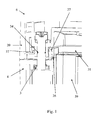
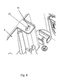
- the subject of the invention is therefore an electrical appliance 1, such as, for example, a switch and / or connection socket for electrical plug, intended to be mounted projecting against or embedded in a wall, comprising at least one electrical functional block, a mounting member 4 for mounting to the wall and fixing said at least one functional block, such as a box for a surface mounting or a flat support for a flush mounting, and a cover 5, defining a main plane 12, forming the front of the electrical apparatus 1 visible after installation, and placed on the mounting element 4.
- the cover 5 may allow the user to interact with the at least one functional block, such as allow him to connect an electrical plug to a power unit of the base type or to switch a function block of the switch type.
- the cover 5 may alternatively completely close the mounting element 4 by making the at least one functional block inaccessible.
- the at least one functional block is then controlled by at least one handle 28 present in the cover 5 and on which a user can act, the functional block can be monostable or bistable, said unless a lever 28 is generally removable.
- the cover 5 can also fulfill a display function, for example by integrating a screen. As will be described later, the cover 5 can also take the form of a plate 20 in which at least one trim 21 is mounted.
- the main plane 12 is parallel to the wall.
- the electrical apparatus 1 comprises an interface joint 26 between the mounting element 4 and the cover 5, as well as at least one cover fixing means 6, capable of fixing said cover 5 directly.
- the mounting element 4 comprising at least one buffer element 3, deformed when the cover 5 is fixed to the mounting element 4 and able to compensate at least partially, by a gradual reduction of its own deformation in time, the aging which takes place in the interface joint 26, this aging being in particular due to a relaxation of stress in the interface joint 26, generally made of polymer.
- the at least one attachment means 6 is masked by a switch lever 28, which allows for a discrete mounting.
- the interface seal 26 makes it possible to guarantee the tightness of the contact zone between the mounting element 4 and the cover 5, and is therefore compressed when the cover 5 is correctly mounted against the mounting element 4 , at least immediately after the first mounting of the cover 5.
- the at least one fastening means 6 directly attaches the cover 5 to the mounting member 4, sufficiently close so that the interface seal 26 is normally compressed. It may, for example, be of a simple screw. An advantageous embodiment of the fastening means 6 is described below.
- the at least one fastening means 6 attach the cover 5 to the mounting member 4 with sufficient force to permanently compress the interface seal 26 between them.
- the fastening means 6 thus exerts on the cover 5 a force sufficient for the interface seal 26 to be compressed, at least after installation.
- the cover 5, once installed remains in its position sufficiently close to the mounting element 4 so that the fastening means 6 is compressed, but is not tightened after installation. The deformation imposed on the interface joint 26 is therefore constant.
- the interface seal 26 is subject to aging, in particular by stress relaxation, which essentially consists of a gradual reduction of the force that the interface seal 26 opposes to its own deformation, the latter resulting in fact from the holding the cover 5 in position against the mounting element 4, under the action of the at least one fastening means 6.
- the aging thus has the effect of reducing the capabilities of the interface seal 26, and therefore also the sealing that it helps to get.
- the buffer element 3 thus has the effect of progressively compensating over time for this aging, and more particularly the relaxation of stresses, by slowing the reduction of the pressure exerted on the interface joint 26, between the cover 5 and the element. 4. To do this, it is the deformation imposed on the interface joint 26 which is gradually increased. In the absence of such a buffer element 3, it is essentially the deformation of the interface joint 26 that the at least one fastening means 6 maintains substantially constant, which leads to the relaxation of stresses described above. As described below, the buffer element 3 progressively reduces the space available for the interface seal 26 as the interface seal 26 reduces its resistance to deformation.
- FIG. 10a illustrates the role of the buffer element 3.
- FIG. figure 10a shows a situation where both the interface joint 26 and the buffer element 3 are deformed.
- the deformation of the interface seal 26 does not change, but the associated pressure on the interface seal 26 decreases gradually over time, which has the effect of damaging the seal .
- the buffer element 3 is less subject to stress relaxation than the interface joint 26, the aging of the latter is compensated for by the reduction, in time, of the deformation by compression of the buffer element 3, figure 10b .
- the buffer element 3 therefore has the effect of gradually reducing the space available for the interface seal 26 in time. This reduction thus tends to compensate for the decrease in the pressure experienced by the interface seal 26.
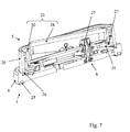
- the cover 5 comprises, firstly, a plate 20 having at least one opening 31, and, d on the other hand, at least one embellisher 21 compatible with the at least one functional block and placed in said at least one opening 31 as well as at least one inner seal 27 installed between said plate 20 and said at least one hubcap 21, the means 6 acting on the at least one trim 21 so that the plate 20 is held between said at least one trim 21 and the mounting element 4, the buffer element 3 being further able to compensate, by a progressive reduction of its deformation, the aging which takes place in the at least one internal seal 27, in particular the relaxation of stresses.
- the plate 20 may be standard, while the hubcap 21 is specific to the functional block.
- the hubcap 21 may be, for example, a hubcap 21 comprising a well 29 for electrical plug or comprising a switch lever 28 and its base 30.
- the compensation for aging in the at least one internal seal 27 is the same as that described for the interface seal 26.
- the cover 5 is thus in at least two parts, namely the plate 20 and at least one trim 21, at least one inner seal 27 must be mounted in the cover 5 to ensure the tightness of the cover 5 itself.
- the inner seal 27 is in the form of a section of material extending along a closed contour, placed around the opening 31, such as an O-ring or a lip seal.
- the at least one internal seal 27 can be obtained by overmoulding on the plate 20, or even the trim 21, or take the form of an independent piece, mounted in the cover 5.
- the aging of the inner seal 27, placed between the hubcap and the plate 20, is, in the same way as for the interface joint, between the plate 20 and the mounting element 4, compensated by the buffer element 3.
- the electrical apparatus 1 has a plurality of functional blocks, possibly different, a single cover 5, comprising a single plate 20 and a plurality of trim 21, each hubcap 21 corresponding to a functional block, each hub cover 21 being held by at least two fastening means 6.
- the cover 5 has a plurality of hubcaps 21 and therefore as many openings 31 and internal seals 27 guaranteeing the seal between the plate 20 and the hubcap 21. In this case, it is particularly interesting to make the internal seals 27 in one piece.
- the at least one cover fixing means 6 is able, on the one hand, in a so-called locked position of a latch 7 that comprises the at least one attachment means 6, to hold the cover 5 directly relative to the mounting element 4, and, secondly, in a so-called free position of said latch 7, not to hold the cover 5 relative to the mounting element 4, the passage of the position locked in the free position by rotating less than a turn of said latch 7 about an axis 8 substantially perpendicular to the main plane 12, in particular a quarter turn, which makes it possible to mount the cover 5 on the particularly ergonomic mounting element 4.
- the transition from the locked position to the free position is done without translation parallel to the axis 8, which allows the installer not to assimilate this locking or unlocking movement to a fixing movement of a screw provided. a thread.
- one end of the latch 7 bears on the cover 5, preferably on the plate 20, in particular on the base 30 for a switch, the other end bearing on the mounting element 4, which therefore allows the at least one fastening means 6 to directly hold the cover 5 to the mounting member 4.
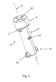
- the latch 7 essentially takes the form of a rod 10, having a body 11 and, on the one hand, a head 9 for its actuation, said body 11 being thinner than said head 9, and on the other hand, a tip 17 having at least one flange 18, projecting from the body 11 of the rod 10, which allows the latch 7 to be retained relative to the mounting element 4 and relative to the lid 5, on the one hand, thanks to said at least one flange 18 resting in the mounting element 4, and, on the other hand, thanks to the head 9 resting in the cover 5.
- the fact of passing from the locking position in the free position has the effect of disengaging from its stop the head 9 and / or the at least one wing 18 of the tip 17.
- grooves 19 for actuation by means of a flat tool type screwdriver are provided on the lock 7, in particular on the or a head 9 of a rod 10 which forms the lock 7. It is thanks to these grooves that the installer can create the rotational movement to move from the locked position to the free position and vice versa.
- the at least one a fixing means 6 comprises at least one locking support surface 13 for the latch 7, against which the latter can rest to hold the cover 5 to the mounting element 4 in the locked position, in particular a surface of locking support 13 arranged on the buffer element 3.
- the lid 5 is thus held against the mounting element 4 by the latch 7, resting, for its head 9, in the lid 5, and for its tip 17 , in particular the flange 18, on the locking bearing surface 13.
- the lid 5 When the latch 7 bears against the locking bearing surface 13, the lid 5 is kept sufficiently close to the mounting element 4 so that the buffer element 3 and 1 interface seal 26 n / a are compressed, in a complementary manner as described above, as well as, in the same way, the at least one possible internal seal 27.
- the at least one fastening means 6 comprises at least one guiding surface 14 in the extension of the at least one locking bearing surface 13, on which the lock 7 can circulate to the at least one locking bearing surface 13 by bringing the cover 5 closer to the mounting element 4.
- the flange circulates on the guiding surface 14, which has a helical shape, which has the effect of bringing the cover 5 of the mounting element 4, and therefore to compress the element buffer 3 and the interface joint 26, as well as the at least one possible internal seal 27. It is therefore not necessary to press the cover 5 against the mounting element 4 before moving from the free position to the locking position, since the circulation on the guide surface 14 has the effect of bringing the cover 5 of the mounting element 4.
- the mounting of the cover is therefore easier for the installer.
- the guide surface 14 thus takes the form of a helix which transforms the rotational movement of the latch 7 into a translation movement.
- the flange 18 is in abutment against the locking bearing surface 13.
- An inverse movement must be made to move from the locking position to the free position.
- the wing 18 then leaves the locking bearing surface 13 and circulates on the guide surface 14, progressively allowing the head 9 to move away from the mounting element 4 and is therefore to the cover 5, taken between them, to move away too.
- the wing 18 then leads to a first clearance 16 arranged in the mounting element 4, which allows to completely detach the cover 5, since the wing 18 is then more restrained against the mounting element 4 but can freely circulate the first clearance 16.
- the buffer element 3 carries the at least one locking support surface 13 as well as the at least one guiding surface 14 and takes the form of an insert 15 placed inside the mounting member 4, and deformed when the latch 7 is in the locking position.
- the use of an insert makes it easier to manufacture the buffer element 4.
- the insert 15 is a metal washer, which guarantees a longer duration of the aging compensation. This metal washer is placed in the mounting element 4, and has a cutout allowing it to be traversed by the tip 17 of the latch 7, in particular a cut in the form of an oblong hole in the case where the tip 17 presents two wings 18.
- the at least one fixing means 6 has, at the level of the mounting element 4, a first orifice 23 in which the body 11 of the rod 10 can slide and pivot, as well as at least a first clearance 16 in which the at least one wing 18 can slide when the latch 7 is in the free position, thus making it possible to disengage the cover 5 and the latch 7 with respect to the mounting element 4 when said latch 7 is in the free position
- the at least one fastening means 6 has a through hole 38, arranged in the cover 5, in particular in the at least one hubcap 21 or a hubcap 21 that includes the cover 5, in which the body 11 of the rod 10 can slide and rotate but in which the head 9 can not circulate, and at least a second clearance 32 in which the at least one wing 18 can slide.
- the passage opening 38 and the second clearance 32 are arranged in a hollow stud 24 of the cover 5 accommodated in a passage 37 in the plate 20 or a plate 20 that includes the cover 5, thus making it possible to disengage the at least a latch 7 of the cover 5 by passing the tip 17. If the at least a second clearance 32 of the cover 5 is located vis-à-vis the first clearance 16 of the mounting member 4 when the cover 5 is mounted on said mounting element 4, the latch 7 can, in its free position, be disengaged from both the cover 5 and the mounting element 4.
- the tip 17 is provided with two wings 18 projecting from the body 11 of the rod 10 and diametrically opposed, the free position and the locked position being separated by a quarter-turn rotation.
- the various other elements of the fastening means 6 and the apparatus 1 itself are adapted to this number of flanges 18: the passage opening 38 is provided with two diametrically opposed second recesses 32, the first orifice 23 is provided with two diametrically opposed first clearances 16 thus making it possible to move from the free position to the locked position independently of the direction of rotation of the at least one lock 7, the fastening means 6 has two diametrically opposite locking bearing surfaces 13 and two adapted guide surfaces 14, the insert 15 having an oblong hole for the simultaneous passage of the two wings 18.
- a different number of wings 18 and different angular differences are possible.
- the at least one fastening means 6 has at least one lug 34 and at least one housing 35 for said lug 34, arranged so as to limit the translation of the latch 7, relative to to the cover 5, parallel to the axis 8, in particular a housing 35 in the form of a circumferential groove, the lug 34 and the housing 35 being, for one, arranged at the latch 7, and for the other, at the cover 5, in particular at the hubcap 21 or at a hubcap 21 that includes the cover 5.
- the at least one lug 34 and the at least one housing 35 are arranged to further limit the rotation of the latch 7 about the axis 8 substantially from the free position.
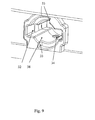
- the Figures 1 to 4 and 9 show that the cover 5, and more precisely the plate 20, has a lug 34 which comes into a housing 35 of the latch 7, of corresponding dimensions, thus making it possible to hold the latch 7 relative to the lid 5, both in a perpendicular axial displacement at the main plane 12, that is to say in axial displacement along the axis 8, only in a rotation about this axis 8.
- the cap lock 7 is therefore guaranteed, since it is held in the cover 5.
- the installer knows that when the latch 7 is stabilized in an angular position, the latter corresponds to the free position.
- the lock 7 can be put in the free position before mounting and maintained until the fixing of the cover 5 on the mounting member 4 by rotation of the lock 7 between the free position and the locking position .
- the figure 1 shows that the lug 34 is mounted in the hollow stud 24. Due to the elasticity of the latter, it remains possible to disengage the lug 34 of the housing 35 by a rotation of the latch 7.
- the at least one attachment means 6 has, on the one hand, at least one stop element 2, arranged at the level of the lock 7, and in particular under the head 9 or a head 9 of a rod 10 includes the lock 7, and, secondly, at least one abutment face 33, arranged in the cover 5 and in contact with which comes the at least one abutment member 2 when the latch 7 is in the locking position or when it undergoes a rotational movement of greater amplitude than that required when moving from the free position to the locking position, which prevents the installer from manipulating the latch 7 like a screw rotating in the vacuum and thus has the impression that the electrical appliance 1 is defective, but also to avoid the degradation of the electrical appliance 1 if the installer makes the latch 7 too large a movement or too much torque .
- the at least one embellisher 21 is held by two fixing means 6, arranged near two opposite edges of said trim 21 and offset with respect to one another, the electrical apparatus 1 comprising in addition, two attachment means 22 of the hubcap 21 to the plate 20, arranged symmetrically to the two locks 7, and consisting essentially each of a tab provided with hooks and extending from the hubcap 21, intended to come cling in a hole provided in the plate 20, thus allowing a good mechanical strength and a good fixing of the cover 5 on the mounting element 4 while limiting the number of operations to be performed by the installer as well the price of such an electric appliance 1.
- the electrical apparatus 1 further comprises a rear seal 25, at the face of the mounting member 4 intended to be in contact with the wall, the interface seal 26 and the at least one internal seal 27 being made in one piece, in particular by overmoulding on the cover 5 or on the plate or plate 20 that includes the cover 5, thereby ensuring additional sealing between the wall and the electrical appliance 1 .
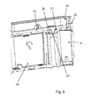
- the mounting element 4 consists of a box for the surface mounting of the electrical apparatus 1, having a receiving cavity 39 for the at least one functional block, the latch 7 terminating, for one of its ends, in particular the or a point 17, within the mounting element 4 in a zone not communicating with the receiving cavity 39, the box including, in addition, hooks for latching the at least one functional block.
- the latch 7 terminates outside the cavity 39 prevents reception that the different orifices designed to accommodate it can bring water or other particles too close to the electrical device 1.
Landscapes
- Engineering & Computer Science (AREA)
- Architecture (AREA)
- Civil Engineering (AREA)
- Structural Engineering (AREA)
- Casings For Electric Apparatus (AREA)
Claims (16)
- Elektrisches Gerät (1), wie beispielsweise ein Schalter und/oder ein Verbindungssockel für elektrische Verbindungsstecker, ausgelegt, vorspringend an oder unter Putz in einer Wand montiert zu werden, umfassend wenigstens einen elektrischen Funktionsblock, ein Montageelement (4) für die Montage an der Wand und zur Befestigung des wenigstens einen Funktionsblocks, wie etwa ein Gehäuse für eine vorspringende Montage oder ein flacher Träger für eine Unterputzmontage, und einen Deckel (5), der eine Hauptebene (12) definiert, die sichtbare Vorderseite des elektrischen Geräts (1) nach der Installation bildet und auf dem Montageelement (4) angeordnet ist, wobei das elektrische Gerät (1) eine Schnittstellendichtung (26) zwischen dem Montageelement (4) und dem Deckel (5) sowie wenigstens ein Fixierungsmittel (6) des Deckels (5), das geeignet ist, den Deckel (5) direkt am Montageelement (4) zu befestigen und wenigstens ein Pufferelement (3) umfasst, das sich verformt, wenn der Deckel (5) an dem Montageelement (4) befestigt ist, und das geeignet ist, durch eine progressive Verringerung der eigenen Deformation wenigstens teilweise die Alterung über die Zeit zu kompensieren, die in der Schnittstellendichtung (26) stattfindet, umfasst, dadurch gekennzeichnet, dass
das wenigstens eine Fixierungsmittel (6) wenigstens eine Führungsfläche (14) umfasst, auf der ein Riegel (7), welcher das Fixierungsmittel (6) umfasst, sich bewegen kann, um von einer freien Position in eine Verriegelungsposition zu gelangen, indem der Deckel (5) sich dem Montageelement (4) nähert. - Elektrisches Gerät (1) nach Anspruch 1, dadurch gekennzeichnet, dass der Deckel (5) einerseits eine Platte (20) umfasst, die wenigstens eine Öffnung (31) aufweist, und andererseits wenigstens eine Blende (21), die mit dem wenigstens einen Funktionsblock kompatibel ist und in der wenigstens einen Öffnung (31) angeordnet ist sowie wenigstens eine innere Dichtung (27), die zwischen der Platte (20) und der wenigstens einen Blende (21) angeordnet ist, wobei das Fixierungsmittel (6) auf die wenigstens eine Blende (21) wirkt, so dass die Platte (20) zwischen der wenigstens eine Blende (21) und dem Montageelement (4) gehalten ist, wobei das Pufferelement (3) darüber hinaus ausgelegt ist, durch eine progressive Reduktion seiner Deformation die Alterung, die in der wenigstens einen internen Dichtung (27) stattfindet, zu kompensieren.
- Elektrisches Gerät (1) nach einem der Ansprüche 1 oder 2, dadurch gekennzeichnet, dass das wenigstens eine Fixierungsmittel (6) des Deckels (5) ausgelegt ist, einerseits in einer geschlossenen Position des Riegels (7), den das wenigstens eine Fixierungsmittel (6) umfasst, den Deckel (5) bezüglich des Montageelements (4) direkt zu halten und andererseits in einer freien Position des Riegels (7) den Deckel (5) bezüglich des Montageelements (4) nicht zu halten, wobei der Übergang von der verriegelten Position in die freie Position durch wenigstens eine volle Umdrehung des Riegels (7) um eine Achse (8) im Wesentlichen senkrecht zur Hauptebene (12) stattfindet.
- Elektrisches Gerät (1) nach Anspruch 3, dadurch gekennzeichnet, dass der Riegel (7) im Wesentlichen die Form eines Stiftes (10) annimmt, welcher einen Körper (11) aufweist sowie einerseits einen Kopf (9) für seine Betätigung, wobei der Körper (11) dünner als der Kopf (9) ist, und andererseits eine Spitze (17), welche wenigstens einen Flügel (18) aufweist, der bezüglich des Körpers (11) des Stiftes (10) vorsteht.
- Elektrisches Gerät (1) nach einem der Ansprüche 3 oder 4, dadurch gekennzeichnet, dass das wenigstens eine Fixierungsmittel (6) wenigstens eine Verriegelungsanschlagsfläche (13) für den Riegel (7) umfasst, gegen den sich letzterer abstützen kann, um den Deckel (5) an dem Montageelement (4) in der verriegelten Position zu halten, insbesondere eine Verriegelungsanschlagsfläche (13), die auf dem Pufferelement (3) vorgesehen ist.
- Elektrisches Gerät (1) nach Anspruch 5, dadurch gekennzeichnet, dass das wenigstens eine Fixierungsmittel (6) wenigstens eine Führungsfläche (14) in der Verlängerung der wenigstens einen Verriegelungsanschlagsfläche (13) aufweist, auf der der Riegel (7) sich bis an die wenigstens eine Verriegelungsanschlagsfläche (13) bewegen kann, indem der Deckel (5) sich dem Montageelement (4) nähert.
- Elektrisches Gerät (1) nach Anspruch 6, dadurch gekennzeichnet, dass das Pufferelement (3) die wenigstens eine Verriegelungsanschlagsfläche (13) sowie die wenigstens eine Führungsfläche (14) trägt und die Form eines Aufsteckteils (15) annimmt, das innerhalb des Montagelements (4) angeordnet ist und sich verformt, wenn der Riegel (7) sich in der Verriegelungsposition befindet.
- Elektrisches Gerät (1) nach Anspruch 7, dadurch gekennzeichnet, dass das Aufsteckteil (15) eine Metallscheibe ist.
- Elektrisches Gerät (1) nach einem der Ansprüche 3 bis 8, dadurch gekennzeichnet, dass das wenigstens eine Fixierungsmittel (6) wenigstens eine Kralle (34) und wenigstens eine Aufnahme (35) für die Kralle (34) aufweist, die so angeordnet sind, um die Bewegungsstrecke des Riegels (7) bezüglich des Deckels (5) parallel zu der Achse (8) zu beschränken, insbesondere eine Aufnahme (35) in Form einer kreisförmigen Nut, wobei die Kralle (34) und die Aufnahme (35) für den einen auf Ebene des Riegels (7) und für den anderen auf Ebene des Deckels (5) angebracht sind, insbesondere auf Ebene der Blende (21) oder einer Blende (21), die der Deckel (5) umfasst.
- Elektrisches Gerät (1) nach Anspruch 9, dadurch gekennzeichnet, dass die wenigstens eine Kralle (34) und die wenigstens eine Aufnahme (35) so angeordnet sind, um darüber hinaus die Rotation des Riegels (7) um die Achse (8) im Wesentlichen aus der freien Position zu beschränken.
- Elektrisches Gerät (1) nach einem der Ansprüche 3 bis 10, dadurch gekennzeichnet, dass das wenigstens eine Fixierungsmittel (6) einerseits wenigstens ein Anschlagselement (2), das im Bereich des Riegels (7) vorgesehen ist, und insbesondere auf dem Kopf (9) oder einem Kopf (9) eines Stiftes (10), den der Riegel (7) umfasst, und andererseits wenigstens eine Anschlagsseite (33), die in dem Deckel (5) angebracht ist und in Kontakt mit dem wenigstens einen Anschlagselement (2) kommt, wenn der Riegel (7) sich in der Verriegelungsposition befindet oder eine Drehbewegung mit einer größeren Amplitude ausführt als die, die vom Übergang von der freien Position in die Verriegelungsposition notwendig wäre, umfasst.
- Elektrisches Gerät (1) nach einem der Ansprüche 3 bis 11, dadurch gekennzeichnet, dass die Nuten (19) für die Betätigung mittels eines flachen Werkzeugs der Art Schraubendreher auf der Verriegelung (7) vorgesehen sind, insbesondere auf dem oder einem Kopf (9) eines Stiftes (10), der den Riegel (7) bildet.
- Elektrisches Gerät (1) nach einem der Ansprüche 2 bis 12, dadurch gekennzeichnet, dass die wenigstens eine Blende (21) mittels zweier Fixierungsmittel (6) gehalten ist, die in der Nähe von zwei gegenüberliegenden Rändern der Blende (21) angeordnet und gegeneinander versetzt sind, wobei das elektrische Gerät (1) darüber hinaus zwei Ankoppelmittel (22) von der Blende (21) an die Platte (20) umfasst, die symmetrisch zu zwei Riegeln (7) angeordnet sind und im Wesentlichen jeweils aus einer Klaue mit einem Haken bestehen und sich von der Blende (21) erstrecken, und die ausgelegt ist, um in eine in der Platte (20) vorgesehen Öffnung einzugreifen.
- Elektrisches Gerät (1) nach einem der Ansprüche 1 bis 13, dadurch gekennzeichnet, dass das elektrische Gerät (1) darüber hinaus eine hintere Dichtung (25) im Bereich der Seite des Montageelements (4) aufweist, die ausgelegt ist, in Kontakt mit der Wand zu kommen, wobei die Schnittstellendichtung (26) und die wenigstens eine innere Dichtung (27) einstückig ausgebildet sind, insbesondere an dem Deckel (5) oder an der oder einer Platte (20), die der Deckel (5) umfasst, angeformt sind.
- Elektrisches Gerät (1) nach einem der Ansprüche 1 bis 14, dadurch gekennzeichnet, dass das Montageelement (4) aus einem Gehäuse für die vorspringende Montage des elektrischen Geräts (1) besteht, wobei es eine Aufnahmevertiefung (39) für den wenigstens einen Funktionsblock aufweist, wobei der Riegel (7) mit einem seiner Enden, nämlich die oder eine Spitze (17) im Inneren des Montageelements (4) an eine Zone anstößt, die nicht mit der Aufnahmevertiefung (39) kommuniziert, wobei das Gehäuse darüber hinaus insbesondere Haken für die Verrastung des wenigstens einen Funktionsblocks aufweist.
- Elektrisches Gerät (1) nach einem der Ansprüche 1 bis 15, dadurch gekennzeichnet, dass es eine Vielzahl von eventuell unterschiedlichen Blöcken aufweist, einen einzigen Deckel (5), der eine einzige Platte (20) und eine Vielzahl von Blenden (21) aufweist, wobei jede Blende (21) mit einem Funktionsblock korrespondiert und wobei jede Blende (21) mittels zweier Fixierungsmittel (6) gehalten ist.
Priority Applications (3)
| Application Number | Priority Date | Filing Date | Title |
|---|---|---|---|
| ES12305204.5T ES2504119T3 (es) | 2012-02-22 | 2012-02-22 | Aparato eléctrico estanco con elemento tampón |
| PT12305204T PT2632002E (pt) | 2012-02-22 | 2012-02-22 | Aparelho eléctrico estanque com elemento tampão |
| EP20120305204 EP2632002B1 (de) | 2012-02-22 | 2012-02-22 | Dichtes elektrisches Gerät mit Pufferelement |
Applications Claiming Priority (1)
| Application Number | Priority Date | Filing Date | Title |
|---|---|---|---|
| EP20120305204 EP2632002B1 (de) | 2012-02-22 | 2012-02-22 | Dichtes elektrisches Gerät mit Pufferelement |
Publications (2)
| Publication Number | Publication Date |
|---|---|
| EP2632002A1 EP2632002A1 (de) | 2013-08-28 |
| EP2632002B1 true EP2632002B1 (de) | 2014-06-18 |
Family
ID=45851446
Family Applications (1)
| Application Number | Title | Priority Date | Filing Date |
|---|---|---|---|
| EP20120305204 Active EP2632002B1 (de) | 2012-02-22 | 2012-02-22 | Dichtes elektrisches Gerät mit Pufferelement |
Country Status (3)
| Country | Link |
|---|---|
| EP (1) | EP2632002B1 (de) |
| ES (1) | ES2504119T3 (de) |
| PT (1) | PT2632002E (de) |
Families Citing this family (2)
| Publication number | Priority date | Publication date | Assignee | Title |
|---|---|---|---|---|
| DE102016014660A1 (de) * | 2016-12-09 | 2018-06-14 | Dürr Systems Ag | Verschluss-Vorrichtung zur Anbringung an einen Roboter |
| IT202300011247A1 (it) * | 2023-06-01 | 2024-12-01 | Bticino Spa | Custodia per il montaggio superficiale a parete di almeno un apparecchio elettrico |
Family Cites Families (4)
| Publication number | Priority date | Publication date | Assignee | Title |
|---|---|---|---|---|
| DE3309593A1 (de) | 1983-03-17 | 1984-09-20 | Brown, Boveri & Cie Ag, 6800 Mannheim | Elektrischer schalter oder taster mit zwei grossflaechigen betaetigungswippen |
| DE9110236U1 (de) * | 1991-08-19 | 1991-12-19 | Hans-Joachim Bernstein Compact-Gehäuse GmbH, 4955 Hille | Klemmengehäuse |
| FR2823905B1 (fr) | 2001-04-23 | 2004-01-30 | Legrand Sa | Dispositif de commande d'appareillages electriques etanche |
| DE10234727A1 (de) | 2002-07-30 | 2003-08-07 | Siemens Ag | Schalter |
-
2012
- 2012-02-22 PT PT12305204T patent/PT2632002E/pt unknown
- 2012-02-22 EP EP20120305204 patent/EP2632002B1/de active Active
- 2012-02-22 ES ES12305204.5T patent/ES2504119T3/es active Active
Also Published As
| Publication number | Publication date |
|---|---|
| EP2632002A1 (de) | 2013-08-28 |
| PT2632002E (pt) | 2014-09-22 |
| ES2504119T3 (es) | 2014-10-08 |
Similar Documents
| Publication | Publication Date | Title |
|---|---|---|
| FR2902394A1 (fr) | Dispositif de fixation d'un balai d'essuie-glace sur un bras | |
| EP0340161A1 (de) | Elastisches Scharnier für ein Brillengestell | |
| FR3087218A1 (fr) | Ensemble de poignee pour ouvrants de type fenetre ou porte | |
| FR2924080A1 (fr) | Plateforme de connexion d'un balai d'essuie-glace pour vehicule automobile | |
| EP1087075B1 (de) | Permanente Verankerungsvorrichtung | |
| EP2632002B1 (de) | Dichtes elektrisches Gerät mit Pufferelement | |
| EP1182522A1 (de) | Befestigungsvorrichtung | |
| FR3060101B1 (fr) | Dispositif de connexion de luminaire | |
| FR2893969A1 (fr) | Dispositif de verrouillage | |
| FR2794787A1 (fr) | Dispositif de renvoi de fouillot | |
| EP2632001B1 (de) | Elektrisches Gerät mit im Montagelement fixiertem Deckel | |
| FR2907080A1 (fr) | Dispositif de fixation d'un bras d'essuie-glace de vehicule automobile | |
| FR2897908A1 (fr) | Agencement de fixation | |
| FR2799805A1 (fr) | Dispositif d'ancrage dit permanent | |
| EP3554872B1 (de) | Fahrzeugschiebetür | |
| FR3057896A1 (fr) | Montage d’une commande d’ouverture de porte du type flush | |
| WO2014060666A1 (fr) | Dispositif de bridage d'un verrou pour une porte d'un véhicule automobile et véhicule automobile comprenant un tel dispositif de bridage | |
| EP2632004A1 (de) | Elektrogerät, das mit einem Einsatz zur Befestigung des Deckels ausgestattet ist | |
| EP2824785B1 (de) | Gelenkeinheit eines Gehäuses für Elektrogerät, und Bodendose, die eine solche Einheit umfasst | |
| FR2990010A1 (fr) | Organe de fixation d'un accessoire sur un support ainsi que du support sur une structure | |
| EP0225222B1 (de) | Elektrisches Gerät mit verbessertem Zusammenbau | |
| FR3040946A1 (fr) | Adaptateur pour bras d'essuyage de vehicule automobile | |
| EP4534781A1 (de) | Verriegelungsbeschlag-steuervorrichtung für tür- oder fensterrahmen | |
| FR3157696A1 (fr) | Bouchon à tige pour assurer une fixation de busbarre électrique et une étanchéité | |
| FR2715428A1 (fr) | Serrure de sûreté pour coffrets d'appareillages techniques. |
Legal Events
| Date | Code | Title | Description |
|---|---|---|---|
| PUAI | Public reference made under article 153(3) epc to a published international application that has entered the european phase |
Free format text: ORIGINAL CODE: 0009012 |
|
| AK | Designated contracting states |
Kind code of ref document: A1 Designated state(s): AL AT BE BG CH CY CZ DE DK EE ES FI FR GB GR HR HU IE IS IT LI LT LU LV MC MK MT NL NO PL PT RO RS SE SI SK SM TR |
|
| AX | Request for extension of the european patent |
Extension state: BA ME |
|
| 17P | Request for examination filed |
Effective date: 20131107 |
|
| RBV | Designated contracting states (corrected) |
Designated state(s): AL AT BE BG CH CY CZ DE DK EE ES FI FR GB GR HR HU IE IS IT LI LT LU LV MC MK MT NL NO PL PT RO RS SE SI SK SM TR |
|
| GRAP | Despatch of communication of intention to grant a patent |
Free format text: ORIGINAL CODE: EPIDOSNIGR1 |
|
| RIC1 | Information provided on ipc code assigned before grant |
Ipc: H02G 3/08 20060101AFI20131210BHEP Ipc: H02G 3/14 20060101ALI20131210BHEP |
|
| INTG | Intention to grant announced |
Effective date: 20140108 |
|
| GRAS | Grant fee paid |
Free format text: ORIGINAL CODE: EPIDOSNIGR3 |
|
| GRAA | (expected) grant |
Free format text: ORIGINAL CODE: 0009210 |
|
| AK | Designated contracting states |
Kind code of ref document: B1 Designated state(s): AL AT BE BG CH CY CZ DE DK EE ES FI FR GB GR HR HU IE IS IT LI LT LU LV MC MK MT NL NO PL PT RO RS SE SI SK SM TR |
|
| REG | Reference to a national code |
Ref country code: GB Ref legal event code: FG4D Free format text: NOT ENGLISH |
|
| REG | Reference to a national code |
Ref country code: CH Ref legal event code: EP |
|
| REG | Reference to a national code |
Ref country code: AT Ref legal event code: REF Ref document number: 673839 Country of ref document: AT Kind code of ref document: T Effective date: 20140715 |
|
| REG | Reference to a national code |
Ref country code: IE Ref legal event code: FG4D Free format text: LANGUAGE OF EP DOCUMENT: FRENCH |
|
| REG | Reference to a national code |
Ref country code: DE Ref legal event code: R096 Ref document number: 602012002155 Country of ref document: DE Effective date: 20140731 |
|
| REG | Reference to a national code |
Ref country code: CH Ref legal event code: NV Representative=s name: DR. GRAF AND PARTNER AG INTELLECTUAL PROPERTY, CH |
|
| REG | Reference to a national code |
Ref country code: PT Ref legal event code: SC4A Free format text: AVAILABILITY OF NATIONAL TRANSLATION Effective date: 20140915 |
|
| REG | Reference to a national code |
Ref country code: ES Ref legal event code: FG2A Ref document number: 2504119 Country of ref document: ES Kind code of ref document: T3 Effective date: 20141008 |
|
| PG25 | Lapsed in a contracting state [announced via postgrant information from national office to epo] |
Ref country code: NO Free format text: LAPSE BECAUSE OF FAILURE TO SUBMIT A TRANSLATION OF THE DESCRIPTION OR TO PAY THE FEE WITHIN THE PRESCRIBED TIME-LIMIT Effective date: 20140918 Ref country code: FI Free format text: LAPSE BECAUSE OF FAILURE TO SUBMIT A TRANSLATION OF THE DESCRIPTION OR TO PAY THE FEE WITHIN THE PRESCRIBED TIME-LIMIT Effective date: 20140618 Ref country code: CY Free format text: LAPSE BECAUSE OF FAILURE TO SUBMIT A TRANSLATION OF THE DESCRIPTION OR TO PAY THE FEE WITHIN THE PRESCRIBED TIME-LIMIT Effective date: 20140618 Ref country code: LT Free format text: LAPSE BECAUSE OF FAILURE TO SUBMIT A TRANSLATION OF THE DESCRIPTION OR TO PAY THE FEE WITHIN THE PRESCRIBED TIME-LIMIT Effective date: 20140618 Ref country code: GR Free format text: LAPSE BECAUSE OF FAILURE TO SUBMIT A TRANSLATION OF THE DESCRIPTION OR TO PAY THE FEE WITHIN THE PRESCRIBED TIME-LIMIT Effective date: 20140919 |
|
| REG | Reference to a national code |
Ref country code: NL Ref legal event code: VDEP Effective date: 20140618 |
|
| REG | Reference to a national code |
Ref country code: AT Ref legal event code: MK05 Ref document number: 673839 Country of ref document: AT Kind code of ref document: T Effective date: 20140618 |
|
| REG | Reference to a national code |
Ref country code: LT Ref legal event code: MG4D |
|
| PG25 | Lapsed in a contracting state [announced via postgrant information from national office to epo] |
Ref country code: HR Free format text: LAPSE BECAUSE OF FAILURE TO SUBMIT A TRANSLATION OF THE DESCRIPTION OR TO PAY THE FEE WITHIN THE PRESCRIBED TIME-LIMIT Effective date: 20140618 Ref country code: RS Free format text: LAPSE BECAUSE OF FAILURE TO SUBMIT A TRANSLATION OF THE DESCRIPTION OR TO PAY THE FEE WITHIN THE PRESCRIBED TIME-LIMIT Effective date: 20140618 Ref country code: SE Free format text: LAPSE BECAUSE OF FAILURE TO SUBMIT A TRANSLATION OF THE DESCRIPTION OR TO PAY THE FEE WITHIN THE PRESCRIBED TIME-LIMIT Effective date: 20140618 Ref country code: LV Free format text: LAPSE BECAUSE OF FAILURE TO SUBMIT A TRANSLATION OF THE DESCRIPTION OR TO PAY THE FEE WITHIN THE PRESCRIBED TIME-LIMIT Effective date: 20140618 |
|
| PG25 | Lapsed in a contracting state [announced via postgrant information from national office to epo] |
Ref country code: EE Free format text: LAPSE BECAUSE OF FAILURE TO SUBMIT A TRANSLATION OF THE DESCRIPTION OR TO PAY THE FEE WITHIN THE PRESCRIBED TIME-LIMIT Effective date: 20140618 Ref country code: SK Free format text: LAPSE BECAUSE OF FAILURE TO SUBMIT A TRANSLATION OF THE DESCRIPTION OR TO PAY THE FEE WITHIN THE PRESCRIBED TIME-LIMIT Effective date: 20140618 Ref country code: CZ Free format text: LAPSE BECAUSE OF FAILURE TO SUBMIT A TRANSLATION OF THE DESCRIPTION OR TO PAY THE FEE WITHIN THE PRESCRIBED TIME-LIMIT Effective date: 20140618 Ref country code: RO Free format text: LAPSE BECAUSE OF FAILURE TO SUBMIT A TRANSLATION OF THE DESCRIPTION OR TO PAY THE FEE WITHIN THE PRESCRIBED TIME-LIMIT Effective date: 20140618 |
|
| PG25 | Lapsed in a contracting state [announced via postgrant information from national office to epo] |
Ref country code: AT Free format text: LAPSE BECAUSE OF FAILURE TO SUBMIT A TRANSLATION OF THE DESCRIPTION OR TO PAY THE FEE WITHIN THE PRESCRIBED TIME-LIMIT Effective date: 20140618 Ref country code: NL Free format text: LAPSE BECAUSE OF FAILURE TO SUBMIT A TRANSLATION OF THE DESCRIPTION OR TO PAY THE FEE WITHIN THE PRESCRIBED TIME-LIMIT Effective date: 20140618 Ref country code: PL Free format text: LAPSE BECAUSE OF FAILURE TO SUBMIT A TRANSLATION OF THE DESCRIPTION OR TO PAY THE FEE WITHIN THE PRESCRIBED TIME-LIMIT Effective date: 20140618 Ref country code: IS Free format text: LAPSE BECAUSE OF FAILURE TO SUBMIT A TRANSLATION OF THE DESCRIPTION OR TO PAY THE FEE WITHIN THE PRESCRIBED TIME-LIMIT Effective date: 20141018 |
|
| REG | Reference to a national code |
Ref country code: DE Ref legal event code: R097 Ref document number: 602012002155 Country of ref document: DE |
|
| PLBE | No opposition filed within time limit |
Free format text: ORIGINAL CODE: 0009261 |
|
| STAA | Information on the status of an ep patent application or granted ep patent |
Free format text: STATUS: NO OPPOSITION FILED WITHIN TIME LIMIT |
|
| PG25 | Lapsed in a contracting state [announced via postgrant information from national office to epo] |
Ref country code: DK Free format text: LAPSE BECAUSE OF FAILURE TO SUBMIT A TRANSLATION OF THE DESCRIPTION OR TO PAY THE FEE WITHIN THE PRESCRIBED TIME-LIMIT Effective date: 20140618 |
|
| 26N | No opposition filed |
Effective date: 20150319 |
|
| PG25 | Lapsed in a contracting state [announced via postgrant information from national office to epo] |
Ref country code: SI Free format text: LAPSE BECAUSE OF FAILURE TO SUBMIT A TRANSLATION OF THE DESCRIPTION OR TO PAY THE FEE WITHIN THE PRESCRIBED TIME-LIMIT Effective date: 20140618 |
|
| REG | Reference to a national code |
Ref country code: FR Ref legal event code: PLFP Year of fee payment: 5 |
|
| PG25 | Lapsed in a contracting state [announced via postgrant information from national office to epo] |
Ref country code: MT Free format text: LAPSE BECAUSE OF FAILURE TO SUBMIT A TRANSLATION OF THE DESCRIPTION OR TO PAY THE FEE WITHIN THE PRESCRIBED TIME-LIMIT Effective date: 20140618 |
|
| REG | Reference to a national code |
Ref country code: FR Ref legal event code: PLFP Year of fee payment: 6 |
|
| PG25 | Lapsed in a contracting state [announced via postgrant information from national office to epo] |
Ref country code: SM Free format text: LAPSE BECAUSE OF FAILURE TO SUBMIT A TRANSLATION OF THE DESCRIPTION OR TO PAY THE FEE WITHIN THE PRESCRIBED TIME-LIMIT Effective date: 20140618 Ref country code: BG Free format text: LAPSE BECAUSE OF FAILURE TO SUBMIT A TRANSLATION OF THE DESCRIPTION OR TO PAY THE FEE WITHIN THE PRESCRIBED TIME-LIMIT Effective date: 20140618 Ref country code: HU Free format text: LAPSE BECAUSE OF FAILURE TO SUBMIT A TRANSLATION OF THE DESCRIPTION OR TO PAY THE FEE WITHIN THE PRESCRIBED TIME-LIMIT; INVALID AB INITIO Effective date: 20120222 |
|
| REG | Reference to a national code |
Ref country code: FR Ref legal event code: PLFP Year of fee payment: 7 |
|
| PG25 | Lapsed in a contracting state [announced via postgrant information from national office to epo] |
Ref country code: MK Free format text: LAPSE BECAUSE OF FAILURE TO SUBMIT A TRANSLATION OF THE DESCRIPTION OR TO PAY THE FEE WITHIN THE PRESCRIBED TIME-LIMIT Effective date: 20140618 |
|
| PG25 | Lapsed in a contracting state [announced via postgrant information from national office to epo] |
Ref country code: AL Free format text: LAPSE BECAUSE OF FAILURE TO SUBMIT A TRANSLATION OF THE DESCRIPTION OR TO PAY THE FEE WITHIN THE PRESCRIBED TIME-LIMIT Effective date: 20140618 |
|
| P01 | Opt-out of the competence of the unified patent court (upc) registered |
Effective date: 20230606 |
|
| REG | Reference to a national code |
Ref country code: CH Ref legal event code: U11 Free format text: ST27 STATUS EVENT CODE: U-0-0-U10-U11 (AS PROVIDED BY THE NATIONAL OFFICE) Effective date: 20260301 |
|
| PGFP | Annual fee paid to national office [announced via postgrant information from national office to epo] |
Ref country code: LU Payment date: 20260227 Year of fee payment: 15 |
|
| PGFP | Annual fee paid to national office [announced via postgrant information from national office to epo] |
Ref country code: GB Payment date: 20260227 Year of fee payment: 15 |
|
| PGFP | Annual fee paid to national office [announced via postgrant information from national office to epo] |
Ref country code: ES Payment date: 20260302 Year of fee payment: 15 Ref country code: MC Payment date: 20260204 Year of fee payment: 15 |
|
| PGFP | Annual fee paid to national office [announced via postgrant information from national office to epo] |
Ref country code: IE Payment date: 20260227 Year of fee payment: 15 Ref country code: DE Payment date: 20260227 Year of fee payment: 15 |
|
| PGFP | Annual fee paid to national office [announced via postgrant information from national office to epo] |
Ref country code: BE Payment date: 20260227 Year of fee payment: 15 Ref country code: IT Payment date: 20260219 Year of fee payment: 15 |
|
| PGFP | Annual fee paid to national office [announced via postgrant information from national office to epo] |
Ref country code: FR Payment date: 20260225 Year of fee payment: 15 |
|
| PGFP | Annual fee paid to national office [announced via postgrant information from national office to epo] |
Ref country code: TR Payment date: 20260206 Year of fee payment: 15 |
|
| PGFP | Annual fee paid to national office [announced via postgrant information from national office to epo] |
Ref country code: PT Payment date: 20260205 Year of fee payment: 15 Ref country code: CH Payment date: 20260301 Year of fee payment: 15 |