EP2632001B1 - Elektrisches Gerät mit im Montagelement fixiertem Deckel - Google Patents
Elektrisches Gerät mit im Montagelement fixiertem Deckel Download PDFInfo
- Publication number
- EP2632001B1 EP2632001B1 EP12305203.7A EP12305203A EP2632001B1 EP 2632001 B1 EP2632001 B1 EP 2632001B1 EP 12305203 A EP12305203 A EP 12305203A EP 2632001 B1 EP2632001 B1 EP 2632001B1
- Authority
- EP
- European Patent Office
- Prior art keywords
- mounting element
- electrical appliance
- trim
- plate
- cover
- Prior art date
- Legal status (The legal status is an assumption and is not a legal conclusion. Google has not performed a legal analysis and makes no representation as to the accuracy of the status listed.)
- Active
Links
Images


Classifications
-
- H—ELECTRICITY
- H02—GENERATION; CONVERSION OR DISTRIBUTION OF ELECTRIC POWER
- H02G—INSTALLATION OF ELECTRIC CABLES OR LINES, OR OF COMBINED OPTICAL AND ELECTRIC CABLES OR LINES
- H02G3/00—Installations of electric cables or lines or protective tubing therefor in or on buildings, equivalent structures or vehicles
- H02G3/02—Details
- H02G3/08—Distribution boxes; Connection or junction boxes
- H02G3/088—Dustproof, splashproof, drip-proof, waterproof, or flameproof casings or inlets
-
- H—ELECTRICITY
- H02—GENERATION; CONVERSION OR DISTRIBUTION OF ELECTRIC POWER
- H02G—INSTALLATION OF ELECTRIC CABLES OR LINES, OR OF COMBINED OPTICAL AND ELECTRIC CABLES OR LINES
- H02G3/00—Installations of electric cables or lines or protective tubing therefor in or on buildings, equivalent structures or vehicles
- H02G3/02—Details
- H02G3/08—Distribution boxes; Connection or junction boxes
- H02G3/10—Distribution boxes; Connection or junction boxes for surface mounting on a wall
-
- H—ELECTRICITY
- H02—GENERATION; CONVERSION OR DISTRIBUTION OF ELECTRIC POWER
- H02G—INSTALLATION OF ELECTRIC CABLES OR LINES, OR OF COMBINED OPTICAL AND ELECTRIC CABLES OR LINES
- H02G3/00—Installations of electric cables or lines or protective tubing therefor in or on buildings, equivalent structures or vehicles
- H02G3/02—Details
- H02G3/08—Distribution boxes; Connection or junction boxes
- H02G3/14—Fastening of cover or lid to box
Definitions
- the present invention relates to the field of electrical installations for the building, and more particularly to a particular electrical device, including a sealed electrical switch device.
- EP 1 860 748 discloses an electrical switch designed to meet enhanced sealing standards, and which includes a mounting member, which may be a mounting box for surface mounting or a flat frame for flush mounting.
- the apparatus also has a lid, essentially made of two pieces, namely, on the one hand, a plate-shaped frame, and, secondly, a hubcap intended to come into the opening of said plate.
- the plate is snapped to the mounting member, the trim being attached to the plate and locking the latching of the plate to the mounting member in a configuration compressing the joints between the plate and, on the one hand, the mounting element, and, secondly, the hubcap.
- the present invention aims to overcome at least this disadvantage and aims in particular to provide an electrical device of the wall switch type, the attachment of the lid is solid, allowing in particular a good seal, and ergonomic mounting.
- the subject of the invention is an electrical apparatus intended to be mounted projecting against or embedded in a wall, comprising at least one electrical function block, of the switching block type, a mounting element for mounting on the wall. and attaching said at least one functional block, such as a box for a surface mounting or a flat support for a flush mounting, and a cover, placed on the mounting member, the cover comprising, on the one hand, a plate having at least one opening, and, on the other hand, a hubcap, compatible with the at least one functional block, placed in said at least one opening, and comprising a base and a handle, the base having a passage for pads that carry the handle and which are intended to act on the at least one functional block, said passage being closed by an elastic membrane carried by said base and traversed by said pads.
- at least one functional block such as a box for a surface mounting or a flat support for a flush mounting
- a cover placed on the mounting member, the cover comprising, on the one hand, a plate having at least one opening, and,
- This electrical apparatus is characterized in that it has at least one fastening means of the hubcap to the mounting element, the plate being held between the at least one trim and the mounting element.
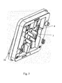
- the invention therefore relates to an electrical apparatus 1 intended to be mounted projecting against or embedded in a wall, comprising at least one electrical function block, of the switching block type, a mounting element 4 for mounting to the wall and fixing said at least one functional block, such as a box for a surface mounting or a flat support for a flush mounting, and a cover 5, placed on the mounting element 4, the cover 5 comprising, on the one hand, a plate 20 having at least one opening 31, and, on the other hand, a hubcap 21, compatible with the at least one functional block, placed in the said at least one opening 31, and comprising a base 30 and a handle 28, the base 30 having a passage 2 for pads 3 that the handle 28 and which are intended to act on the at least one functional block, said passage 2 being closed by an elastic membrane 8 carried by said base 30 and traversed by said pads 3.
- the invention is particularly advantageous in the case where the functional block is a switching block for a switch, but it can also be applied to functional transmission blocks, such as for an electrical base or other types of switchgear. electrical appliances such as radios, domotic control elements, light signals, etc.
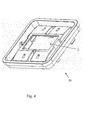
- the latter comprises an interface joint 26, between the mounting element 4 and the cover 5, at least one joint internal 27, between the plate 20 and the at least one hubcap 21, and in particular also a rear seal 25, at the face of the mounting element intended to be in contact with the wall.
- An inner seal 27 is provided for each trim 21, if any.
- the electrical apparatus 1 comprises several hubcaps 21, and therefore as many internal seals 27, they are therefore all in one piece with the interface seal 26.
- the use of a single piece for the various seals present also the advantage, if not overmoulded but simply asked, to simplify the manufacture.
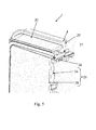
- the electrical apparatus 1 has at least one fastening means 6 of the hubcap 21 to the mounting element 4, the plate 20 being held between the at least one hubcap 21 and the mounting element 4
- the at least one fastening means 6 thus fixes the plate 20 directly to the mounting element 4. It can consist essentially, for example, of a screw, a latching means, an insert to be interposed between the cover and a screw therein, anchored in the mounting member 4, or a latch, in the form of a rod pivoting about its main axis, perpendicular to the mounting wall, between a free position and a locked position.
- the fastening means 6 mechanically holds the cover 5 to the mounting element 4, and is preferentially unlockable, in order to be able to disassemble the cover 5 and access the function block.
- the electrical apparatus 1 is thus formed, in the case of a switch, of a superposition of a mounting element 4, a plate 20, a base 30 and a handle 28, these last three forming the cover 5. These elements are successively supported against each other, and the hubcap 21, essentially formed of a base 30 and a handle 28, is directly attached to the mounting element 4 by at least one fastening means 6.
- the plate 20 is thus caught between, on the one hand, the mounting element 4, and, on the other hand, the hubcap 21 which is anchored to said mounting element 4 by means of the at least one fastening means 6.
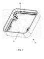
- the handle 28 is, in turn, fixed directly to the base 30, as part of the hubcap 21. It is generally snapped onto the base 30 at the base of the pads 30 for pivoting.
- the plate 20 is taken between, on the one hand, the mounting element 4, and, on the other hand, the hubcap 21 fixed to the mounting element 4 by at least one fastening means 6, makes it possible to ensure that the entire cover 5 is securely held by the mounting element 4, but also to ensure the compression of the joints between the plate 20, which is easily common to different devices of the same range, and, on the one hand, , the mounting element 4, namely an interface joint 26, or, on the other hand, the hubcap 21, namely at least one internal seal 27.
- the handle 28 has, at its rear face, pads 3, in the form of an elongate rib, which act on the switching function block so as to switch the contacts.
- the passage 2 is thus large enough so that the pads 3 are never hindered by the rigid constituent material of the base 30.
- the latter is covered with an elastic membrane 8.
- the membrane 8, covering the passage 2 thus carries orifices at which it is traversed by the pads 3. Given the elasticity of the membrane 8, these holes for stud 3 can easily follow the movement of the pads 3, and the membrane 8 thus ensures the sealing of the passage 2, despite the presence of the pads 3 in the form of movable elements.
- the at least one fixing means 6 fixes the base 30 to the mounting element 4, the plate 20 being held between said base 30 and said mounting member 4.
- the fastening means 6 may indeed be a screw, anchored by its thread in the mounting element 4 and whose head holds the cover 5, and more precisely the base 30 or another part The hub of the screw is then under the handle 28, and is therefore no longer visible.
- the fastening means 6 may alternatively comprise an insert, a quarter-turn key, which is then placed or placed under the handle 28. Since the handle 28 covers a large part of the base 30, the fastening means 6 is invisible when it is under said handle 28.
- the at least one fastening means 6 is operable using a flat tool of the screwdriver type and therefore comprises, for this purpose, a suitable groove.
- the fixing means 6 is preferably actuable from the front face of the electrical appliance 1, at the level of the lid 5. It thus has a groove or a groove clearance which makes it possible to create, using a screwdriver or another flat tool, the movement allowing the fastening means 6 to move from the locked position, in which it holds the cover 5 against the mounting member 4, to the unlocked position, and vice versa.
- the at least one fastening means 6 passes from a locking position, in which it fixes the at least one trim 21 to the mounting element 4, to a free position, in which it does not fix. not the at least one hubcap 21 to the mounting element 4, with a rotation of a portion of a turn, that is to say a rotation of less than one turn.
- the fastening means 6 is therefore preferably locked or unlocked by making a movement of a quarter turn.
- Principles such as quarter-turn or half-turn locks are therefore particularly relevant.
- the rotational movement is around an axis perpendicular to the plane of the cover 5, which corresponds to a rotation movement of the same type as that conventionally used for fixing the mounting element 4 on the wall.
- the rotational movement is around an axis parallel to the plane of the cover 5, which makes it possible to avoid any confusion between the fixing of the cover 5 to the mounting element 4 of any other fastener. . It is indeed important not to confuse the fixing of the cover 5, which has an impact on the seal and must therefore be treated in a particular way, other fasteners.
- This may particularly correspond to an insert, which, in order to lock the fastening means 6, could be slid between, on the one hand, the cover 5, and, more precisely, the hubcap 21, on a surface of support and other on the other hand, the head of a screw anchored in the mounting element 4 and opening beyond said bearing surface of the insert in the cover 5.
- the at least one hubcap 21 is held by two fastening means 6, arranged near two opposite edges of said at least one trim 21 and offset with respect to each other, the electrical apparatus 1 further comprising two hooking means 22 of said at least one trim 21 to the plate 20 , arranged symmetrically to the two fastening means 6, and consisting essentially each of a tab provided with hooks, which extends from said hubcap 21, intended to hook into a hole provided in the plate 20.
Landscapes
- Engineering & Computer Science (AREA)
- Architecture (AREA)
- Civil Engineering (AREA)
- Structural Engineering (AREA)
- Switch Cases, Indication, And Locking (AREA)
- Casings For Electric Apparatus (AREA)
Claims (9)
- Elektrisches Gerät (1), ausgelegt, um vorspringend an oder unter Putz in einer Wand montiert zu werden, umfassend wenigstens einen elektrischen Funktionsblock der Art Umschaltblock, ein Montageelement (4) für die Montage an der Wand und zur Befestigung des wenigstens einen Funktionsblocks, wie etwa ein Gehäuse für eine vorspringende Montage oder ein flacher Träger für eine Unterputzmontage, und einen Deckel (5), der auf dem Montageelement (4) angeordnet ist,
der Deckel (5) umfasst einerseits eine Platte (20), die wenigstens eine Öffnung (31) aufweist und andererseits eine Blende (21), die mit dem wenigstens einen Funktionsblock kompatibel und in die wenigstens eine Öffnung (31) eingesetzt ist und eine Basis (30) und einen Schalthebel (28) umfasst,
die Basis (30) umfasst einen Durchgang (2) für Kontakte (3), welche der Schalthebel (28) trägt und die ausgelegt sind, auf den wenigstens einen Funktionsblock zu wirken, wobei der Durchgang (2) durch eine elastische Membran (8) verschlossen ist, die von der Basis (30) getragen und von den Kontakten (3) durchdrungen ist,
wobei das elektrische Gerät (1) dadurch gekennzeichnet ist, dass es wenigstens ein Fixierungsmittel (6) von der Blende (21) zu dem Montageelement (4) umfasst, wobei die Platte (20) zwischen der wenigstens einen Blende (21) und dem Montageelement (4) gehalten ist. - Elektrisches Gerät (1) nach Anspruch 1, dadurch gekennzeichnet, dass das wenigstens eine Fixierungsmittel (6) die Basis (30) an dem Montageelement (4) befestigt, wobei die Platte (20) zwischen der Basis (30) und dem Montageelement (4) gehalten ist.
- Elektrisches Gerät (1) nach einem der Ansprüche 1 oder 2, dadurch gekennzeichnet, dass das wenigstens eine Fixierungsmittel (6) mittels eines flachen Werkzeugs der Art Schraubendreher betätigbar ist.
- Elektrisches Gerät (1) nach einem der Ansprüche 1 bis 3, dadurch gekennzeichnet, dass das wenigstens eine Fixierungsmittel (6) durch eine Teildrehung von einer Verriegelungsposition, in welcher es die wenigstens eine Blende (21) an dem Montageelement (4) befestigt, in eine freie Position, in der es die wenigstens eine Blende (21) nicht mit dem Montageelement (4) fixiert, übergeht.
- Elektrisches Gerät (1) nach Anspruch 4, dadurch gekennzeichnet, dass die Drehbewegung um eine Achse senkrecht zur Ebene des Deckels (5) durchgeführt wird.
- Elektrisches Gerät (1) nach Anspruch 5, dadurch gekennzeichnet, dass die Drehbewegung um eine Achse parallel zur Ebene des Deckels (5) durchgeführt wird.
- Elektrisches Gerät (1) nach einem der Ansprüche 1 bis 6, dadurch gekennzeichnet, dass es eine Schnittstellendichtung (26) zwischen dem Montageelement (4) und dem Deckel (5), wenigstens eine innere Dichtung (27) zwischen der Platte (20) und der wenigstens einen Blende (21) und insbesondere auch eine hintere Dichtung (25) im Bereich der Seite des Montageelements, die ausgelegt ist, in Kontakt mit der Wand zu stehen, umfasst.
- Elektrisches Gerät (1) nach Anspruch 7, dadurch gekennzeichnet, dass die Schnittstellendichtung (26) und die wenigstens eine innere Dichtung (27) einstückig ausgebildet sind, insbesondere an der Platte (20) angeformt sind.
- Elektrisches Gerät (1) nach einem der Ansprüche 1 bis 8, dadurch gekennzeichnet, dass die wenigstens eine Blende (21) von zwei Fixierungsmitteln (6) gehalten wird, die in der Nähe von zwei gegenüberliegenden Rändern der wenigstens einen Blende (21) angeordnet und gegeneinander versetzt sind, wobei das elektrische Gerät (1) darüber hinaus zwei Ankoppelelemente (22) von der wenigstens einen Blende (21) an die Platte (20) umfasst, die symmetrisch zu den zwei Fixierungsmitteln (6) angeordnet sind und im Wesentlichen jeweils aus einer Kralle mit Haken bestehen, die sich von der Blende (21) erstreckt und die ausgelegt ist, in eine in der Platte (20) vorgesehene Öffnung einzuhaken.
Priority Applications (3)
| Application Number | Priority Date | Filing Date | Title |
|---|---|---|---|
| ES12305203.7T ES2501092T3 (es) | 2012-02-22 | 2012-02-22 | Aparato eléctrico con tapa fijada en el elemento de montaje |
| PT123052037T PT2632001E (pt) | 2012-02-22 | 2012-02-22 | Aparelho eléctrico com tampa fixa no elemento de montagem |
| EP12305203.7A EP2632001B1 (de) | 2012-02-22 | 2012-02-22 | Elektrisches Gerät mit im Montagelement fixiertem Deckel |
Applications Claiming Priority (1)
| Application Number | Priority Date | Filing Date | Title |
|---|---|---|---|
| EP12305203.7A EP2632001B1 (de) | 2012-02-22 | 2012-02-22 | Elektrisches Gerät mit im Montagelement fixiertem Deckel |
Publications (2)
| Publication Number | Publication Date |
|---|---|
| EP2632001A1 EP2632001A1 (de) | 2013-08-28 |
| EP2632001B1 true EP2632001B1 (de) | 2014-06-18 |
Family
ID=45999734
Family Applications (1)
| Application Number | Title | Priority Date | Filing Date |
|---|---|---|---|
| EP12305203.7A Active EP2632001B1 (de) | 2012-02-22 | 2012-02-22 | Elektrisches Gerät mit im Montagelement fixiertem Deckel |
Country Status (3)
| Country | Link |
|---|---|
| EP (1) | EP2632001B1 (de) |
| ES (1) | ES2501092T3 (de) |
| PT (1) | PT2632001E (de) |
Families Citing this family (2)
| Publication number | Priority date | Publication date | Assignee | Title |
|---|---|---|---|---|
| BE1027430B1 (nl) * | 2019-07-16 | 2021-02-15 | Niko Nv | Montagesysteem voor een elektrisch of elektronisch apparaat |
| FR3105559B1 (fr) * | 2019-12-20 | 2023-04-21 | Legrand France | Boîte électrique et appareillage électrique associé |
Family Cites Families (2)
| Publication number | Priority date | Publication date | Assignee | Title |
|---|---|---|---|---|
| CH696899A5 (de) * | 2004-04-05 | 2008-01-15 | Abb Schweiz Ag | Frontplattenbefestigung eines elektrischen Schalters oder Tastensensors. |
| FR2901451B1 (fr) | 2006-05-22 | 2008-07-18 | Legrand France | Appareillage electrique etanche a disposer en saillie ou a encastrer dans une paroi |
-
2012
- 2012-02-22 EP EP12305203.7A patent/EP2632001B1/de active Active
- 2012-02-22 ES ES12305203.7T patent/ES2501092T3/es active Active
- 2012-02-22 PT PT123052037T patent/PT2632001E/pt unknown
Also Published As
| Publication number | Publication date |
|---|---|
| EP2632001A1 (de) | 2013-08-28 |
| ES2501092T3 (es) | 2014-10-01 |
| PT2632001E (pt) | 2014-09-22 |
Similar Documents
| Publication | Publication Date | Title |
|---|---|---|
| FR3042918A1 (fr) | Boite electrique encastrable dans des cloisons d'epaisseurs differentes | |
| EP2632001B1 (de) | Elektrisches Gerät mit im Montagelement fixiertem Deckel | |
| EP1087075B1 (de) | Permanente Verankerungsvorrichtung | |
| EP3172750B1 (de) | Verkleidung für elektrischen schalter und elektrischer schalter mit solch einer verkleidung | |
| EP1149447B1 (de) | Gerätegehalter ,insbesondere für elektrisches gerät und damit ausgerüstetes gehäuse | |
| EP1675236A1 (de) | Halterung für ein elektrisches Gerät | |
| EP1564859A1 (de) | Flanschgehäuse für eine dünne Wand | |
| EP0715383B1 (de) | Anordnung zur Befestigung eines elektrischen Gerätes an einer Tragschiene | |
| EP1675235B1 (de) | Vielfacher Gerätehalter zur horizontalen und vertikalen Montage. | |
| EP3159989B1 (de) | Elektrisches gehäuse zum einbau in eine wand | |
| EP2097960A1 (de) | Träger für ein elektrisches gerät | |
| EP1675240A1 (de) | Halterung für mehrere elektrische Geräte mit indexierten Montage von elektrischen Gerätesockel | |
| EP2632002B1 (de) | Dichtes elektrisches Gerät mit Pufferelement | |
| EP2112734B1 (de) | Elektrogerät zum Aufsetzen auf ein Einbaugehäuse | |
| FR3057715B1 (fr) | Boitier d'appareillage electrique, appareil electrique pour ledit boitier et appareillage electrique comprenant ledit boitier et ledit appareil electrique | |
| FR2999024A1 (fr) | Appareillage electrique et rehausse pour un tel appareillage electrique | |
| CA2914127A1 (fr) | Dispositif d'accouplement de deux demi-cylindres | |
| FR2829781A1 (fr) | Dispositif de mise sous tension d'un faux plafond souple | |
| FR2799805A1 (fr) | Dispositif d'ancrage dit permanent | |
| FR2956259A1 (fr) | Accessoire comportant une griffe de fixation d'un support d'appareillage a une boite murale et appareillage electrique comportant un tel accessoire | |
| CH712040A2 (fr) | Fermoir déployant pour bracelet. | |
| EP1744426B1 (de) | Elektrischer Kasten bestehend aus zwei Elemente die mit einer Zahnstange zusammen befestigt sind | |
| EP2824785B1 (de) | Gelenkeinheit eines Gehäuses für Elektrogerät, und Bodendose, die eine solche Einheit umfasst | |
| EP3644339A1 (de) | Gerät zur unterbrechung eines elektrischen stroms | |
| FR2463514A1 (fr) | Connecteur de batterie |
Legal Events
| Date | Code | Title | Description |
|---|---|---|---|
| PUAI | Public reference made under article 153(3) epc to a published international application that has entered the european phase |
Free format text: ORIGINAL CODE: 0009012 |
|
| AK | Designated contracting states |
Kind code of ref document: A1 Designated state(s): AL AT BE BG CH CY CZ DE DK EE ES FI FR GB GR HR HU IE IS IT LI LT LU LV MC MK MT NL NO PL PT RO RS SE SI SK SM TR |
|
| AX | Request for extension of the european patent |
Extension state: BA ME |
|
| 17P | Request for examination filed |
Effective date: 20131030 |
|
| RBV | Designated contracting states (corrected) |
Designated state(s): AL AT BE BG CH CY CZ DE DK EE ES FI FR GB GR HR HU IE IS IT LI LT LU LV MC MK MT NL NO PL PT RO RS SE SI SK SM TR |
|
| GRAP | Despatch of communication of intention to grant a patent |
Free format text: ORIGINAL CODE: EPIDOSNIGR1 |
|
| RIC1 | Information provided on ipc code assigned before grant |
Ipc: H02G 3/08 20060101AFI20131209BHEP Ipc: H02G 3/14 20060101ALI20131209BHEP |
|
| INTG | Intention to grant announced |
Effective date: 20140109 |
|
| GRAS | Grant fee paid |
Free format text: ORIGINAL CODE: EPIDOSNIGR3 |
|
| GRAA | (expected) grant |
Free format text: ORIGINAL CODE: 0009210 |
|
| AK | Designated contracting states |
Kind code of ref document: B1 Designated state(s): AL AT BE BG CH CY CZ DE DK EE ES FI FR GB GR HR HU IE IS IT LI LT LU LV MC MK MT NL NO PL PT RO RS SE SI SK SM TR |
|
| REG | Reference to a national code |
Ref country code: GB Ref legal event code: FG4D Free format text: NOT ENGLISH |
|
| REG | Reference to a national code |
Ref country code: CH Ref legal event code: EP |
|
| REG | Reference to a national code |
Ref country code: AT Ref legal event code: REF Ref document number: 673838 Country of ref document: AT Kind code of ref document: T Effective date: 20140715 |
|
| REG | Reference to a national code |
Ref country code: IE Ref legal event code: FG4D Free format text: LANGUAGE OF EP DOCUMENT: FRENCH |
|
| REG | Reference to a national code |
Ref country code: DE Ref legal event code: R096 Ref document number: 602012002154 Country of ref document: DE Effective date: 20140731 |
|
| REG | Reference to a national code |
Ref country code: CH Ref legal event code: NV Representative=s name: DR. GRAF AND PARTNER AG INTELLECTUAL PROPERTY, CH |
|
| REG | Reference to a national code |
Ref country code: PT Ref legal event code: SC4A Free format text: AVAILABILITY OF NATIONAL TRANSLATION Effective date: 20140915 |
|
| REG | Reference to a national code |
Ref country code: ES Ref legal event code: FG2A Ref document number: 2501092 Country of ref document: ES Kind code of ref document: T3 Effective date: 20141001 |
|
| PG25 | Lapsed in a contracting state [announced via postgrant information from national office to epo] |
Ref country code: LT Free format text: LAPSE BECAUSE OF FAILURE TO SUBMIT A TRANSLATION OF THE DESCRIPTION OR TO PAY THE FEE WITHIN THE PRESCRIBED TIME-LIMIT Effective date: 20140618 Ref country code: CY Free format text: LAPSE BECAUSE OF FAILURE TO SUBMIT A TRANSLATION OF THE DESCRIPTION OR TO PAY THE FEE WITHIN THE PRESCRIBED TIME-LIMIT Effective date: 20140618 Ref country code: NO Free format text: LAPSE BECAUSE OF FAILURE TO SUBMIT A TRANSLATION OF THE DESCRIPTION OR TO PAY THE FEE WITHIN THE PRESCRIBED TIME-LIMIT Effective date: 20140918 Ref country code: GR Free format text: LAPSE BECAUSE OF FAILURE TO SUBMIT A TRANSLATION OF THE DESCRIPTION OR TO PAY THE FEE WITHIN THE PRESCRIBED TIME-LIMIT Effective date: 20140919 Ref country code: FI Free format text: LAPSE BECAUSE OF FAILURE TO SUBMIT A TRANSLATION OF THE DESCRIPTION OR TO PAY THE FEE WITHIN THE PRESCRIBED TIME-LIMIT Effective date: 20140618 |
|
| REG | Reference to a national code |
Ref country code: NL Ref legal event code: VDEP Effective date: 20140618 |
|
| REG | Reference to a national code |
Ref country code: AT Ref legal event code: MK05 Ref document number: 673838 Country of ref document: AT Kind code of ref document: T Effective date: 20140618 |
|
| REG | Reference to a national code |
Ref country code: LT Ref legal event code: MG4D |
|
| PG25 | Lapsed in a contracting state [announced via postgrant information from national office to epo] |
Ref country code: LV Free format text: LAPSE BECAUSE OF FAILURE TO SUBMIT A TRANSLATION OF THE DESCRIPTION OR TO PAY THE FEE WITHIN THE PRESCRIBED TIME-LIMIT Effective date: 20140618 Ref country code: RS Free format text: LAPSE BECAUSE OF FAILURE TO SUBMIT A TRANSLATION OF THE DESCRIPTION OR TO PAY THE FEE WITHIN THE PRESCRIBED TIME-LIMIT Effective date: 20140618 Ref country code: SE Free format text: LAPSE BECAUSE OF FAILURE TO SUBMIT A TRANSLATION OF THE DESCRIPTION OR TO PAY THE FEE WITHIN THE PRESCRIBED TIME-LIMIT Effective date: 20140618 Ref country code: HR Free format text: LAPSE BECAUSE OF FAILURE TO SUBMIT A TRANSLATION OF THE DESCRIPTION OR TO PAY THE FEE WITHIN THE PRESCRIBED TIME-LIMIT Effective date: 20140618 |
|
| PG25 | Lapsed in a contracting state [announced via postgrant information from national office to epo] |
Ref country code: CZ Free format text: LAPSE BECAUSE OF FAILURE TO SUBMIT A TRANSLATION OF THE DESCRIPTION OR TO PAY THE FEE WITHIN THE PRESCRIBED TIME-LIMIT Effective date: 20140618 Ref country code: EE Free format text: LAPSE BECAUSE OF FAILURE TO SUBMIT A TRANSLATION OF THE DESCRIPTION OR TO PAY THE FEE WITHIN THE PRESCRIBED TIME-LIMIT Effective date: 20140618 Ref country code: RO Free format text: LAPSE BECAUSE OF FAILURE TO SUBMIT A TRANSLATION OF THE DESCRIPTION OR TO PAY THE FEE WITHIN THE PRESCRIBED TIME-LIMIT Effective date: 20140618 Ref country code: SK Free format text: LAPSE BECAUSE OF FAILURE TO SUBMIT A TRANSLATION OF THE DESCRIPTION OR TO PAY THE FEE WITHIN THE PRESCRIBED TIME-LIMIT Effective date: 20140618 |
|
| PG25 | Lapsed in a contracting state [announced via postgrant information from national office to epo] |
Ref country code: IS Free format text: LAPSE BECAUSE OF FAILURE TO SUBMIT A TRANSLATION OF THE DESCRIPTION OR TO PAY THE FEE WITHIN THE PRESCRIBED TIME-LIMIT Effective date: 20141018 Ref country code: PL Free format text: LAPSE BECAUSE OF FAILURE TO SUBMIT A TRANSLATION OF THE DESCRIPTION OR TO PAY THE FEE WITHIN THE PRESCRIBED TIME-LIMIT Effective date: 20140618 Ref country code: AT Free format text: LAPSE BECAUSE OF FAILURE TO SUBMIT A TRANSLATION OF THE DESCRIPTION OR TO PAY THE FEE WITHIN THE PRESCRIBED TIME-LIMIT Effective date: 20140618 Ref country code: NL Free format text: LAPSE BECAUSE OF FAILURE TO SUBMIT A TRANSLATION OF THE DESCRIPTION OR TO PAY THE FEE WITHIN THE PRESCRIBED TIME-LIMIT Effective date: 20140618 |
|
| REG | Reference to a national code |
Ref country code: DE Ref legal event code: R097 Ref document number: 602012002154 Country of ref document: DE |
|
| PLBE | No opposition filed within time limit |
Free format text: ORIGINAL CODE: 0009261 |
|
| STAA | Information on the status of an ep patent application or granted ep patent |
Free format text: STATUS: NO OPPOSITION FILED WITHIN TIME LIMIT |
|
| PG25 | Lapsed in a contracting state [announced via postgrant information from national office to epo] |
Ref country code: DK Free format text: LAPSE BECAUSE OF FAILURE TO SUBMIT A TRANSLATION OF THE DESCRIPTION OR TO PAY THE FEE WITHIN THE PRESCRIBED TIME-LIMIT Effective date: 20140618 |
|
| 26N | No opposition filed |
Effective date: 20150319 |
|
| PG25 | Lapsed in a contracting state [announced via postgrant information from national office to epo] |
Ref country code: SI Free format text: LAPSE BECAUSE OF FAILURE TO SUBMIT A TRANSLATION OF THE DESCRIPTION OR TO PAY THE FEE WITHIN THE PRESCRIBED TIME-LIMIT Effective date: 20140618 |
|
| REG | Reference to a national code |
Ref country code: FR Ref legal event code: PLFP Year of fee payment: 5 |
|
| PG25 | Lapsed in a contracting state [announced via postgrant information from national office to epo] |
Ref country code: MT Free format text: LAPSE BECAUSE OF FAILURE TO SUBMIT A TRANSLATION OF THE DESCRIPTION OR TO PAY THE FEE WITHIN THE PRESCRIBED TIME-LIMIT Effective date: 20140618 |
|
| REG | Reference to a national code |
Ref country code: FR Ref legal event code: PLFP Year of fee payment: 6 |
|
| PG25 | Lapsed in a contracting state [announced via postgrant information from national office to epo] |
Ref country code: BG Free format text: LAPSE BECAUSE OF FAILURE TO SUBMIT A TRANSLATION OF THE DESCRIPTION OR TO PAY THE FEE WITHIN THE PRESCRIBED TIME-LIMIT Effective date: 20140618 Ref country code: SM Free format text: LAPSE BECAUSE OF FAILURE TO SUBMIT A TRANSLATION OF THE DESCRIPTION OR TO PAY THE FEE WITHIN THE PRESCRIBED TIME-LIMIT Effective date: 20140618 Ref country code: HU Free format text: LAPSE BECAUSE OF FAILURE TO SUBMIT A TRANSLATION OF THE DESCRIPTION OR TO PAY THE FEE WITHIN THE PRESCRIBED TIME-LIMIT; INVALID AB INITIO Effective date: 20120222 |
|
| REG | Reference to a national code |
Ref country code: FR Ref legal event code: PLFP Year of fee payment: 7 |
|
| PG25 | Lapsed in a contracting state [announced via postgrant information from national office to epo] |
Ref country code: MK Free format text: LAPSE BECAUSE OF FAILURE TO SUBMIT A TRANSLATION OF THE DESCRIPTION OR TO PAY THE FEE WITHIN THE PRESCRIBED TIME-LIMIT Effective date: 20140618 |
|
| PG25 | Lapsed in a contracting state [announced via postgrant information from national office to epo] |
Ref country code: AL Free format text: LAPSE BECAUSE OF FAILURE TO SUBMIT A TRANSLATION OF THE DESCRIPTION OR TO PAY THE FEE WITHIN THE PRESCRIBED TIME-LIMIT Effective date: 20140618 |
|
| P01 | Opt-out of the competence of the unified patent court (upc) registered |
Effective date: 20230606 |
|
| REG | Reference to a national code |
Ref country code: CH Ref legal event code: U11 Free format text: ST27 STATUS EVENT CODE: U-0-0-U10-U11 (AS PROVIDED BY THE NATIONAL OFFICE) Effective date: 20260301 |
|
| PGFP | Annual fee paid to national office [announced via postgrant information from national office to epo] |
Ref country code: LU Payment date: 20260227 Year of fee payment: 15 |
|
| PGFP | Annual fee paid to national office [announced via postgrant information from national office to epo] |
Ref country code: GB Payment date: 20260227 Year of fee payment: 15 |
|
| PGFP | Annual fee paid to national office [announced via postgrant information from national office to epo] |
Ref country code: ES Payment date: 20260302 Year of fee payment: 15 Ref country code: MC Payment date: 20260204 Year of fee payment: 15 |
|
| PGFP | Annual fee paid to national office [announced via postgrant information from national office to epo] |
Ref country code: IE Payment date: 20260227 Year of fee payment: 15 Ref country code: DE Payment date: 20260227 Year of fee payment: 15 |
|
| PGFP | Annual fee paid to national office [announced via postgrant information from national office to epo] |
Ref country code: BE Payment date: 20260227 Year of fee payment: 15 Ref country code: IT Payment date: 20260219 Year of fee payment: 15 |
|
| PGFP | Annual fee paid to national office [announced via postgrant information from national office to epo] |
Ref country code: FR Payment date: 20260225 Year of fee payment: 15 |
|
| PGFP | Annual fee paid to national office [announced via postgrant information from national office to epo] |
Ref country code: TR Payment date: 20260206 Year of fee payment: 15 |
|
| PGFP | Annual fee paid to national office [announced via postgrant information from national office to epo] |
Ref country code: PT Payment date: 20260205 Year of fee payment: 15 Ref country code: CH Payment date: 20260301 Year of fee payment: 15 |