EP4052984A1 - Traverser, base unit, and mobile unit - Google Patents
Traverser, base unit, and mobile unit Download PDFInfo
- Publication number
- EP4052984A1 EP4052984A1 EP20883125.5A EP20883125A EP4052984A1 EP 4052984 A1 EP4052984 A1 EP 4052984A1 EP 20883125 A EP20883125 A EP 20883125A EP 4052984 A1 EP4052984 A1 EP 4052984A1
- Authority
- EP
- European Patent Office
- Prior art keywords
- travel
- roller
- unit
- moving unit
- drive
- Prior art date
- Legal status (The legal status is an assumption and is not a legal conclusion. Google has not performed a legal analysis and makes no representation as to the accuracy of the status listed.)
- Pending
Links
Images


Classifications
-
- B—PERFORMING OPERATIONS; TRANSPORTING
- B65—CONVEYING; PACKING; STORING; HANDLING THIN OR FILAMENTARY MATERIAL
- B65G—TRANSPORT OR STORAGE DEVICES, e.g. CONVEYORS FOR LOADING OR TIPPING, SHOP CONVEYOR SYSTEMS OR PNEUMATIC TUBE CONVEYORS
- B65G13/00—Roller-ways
- B65G13/02—Roller-ways having driven rollers
- B65G13/06—Roller driving means
- B65G13/07—Roller driving means having endless driving elements
-
- B—PERFORMING OPERATIONS; TRANSPORTING
- B65—CONVEYING; PACKING; STORING; HANDLING THIN OR FILAMENTARY MATERIAL
- B65G—TRANSPORT OR STORAGE DEVICES, e.g. CONVEYORS FOR LOADING OR TIPPING, SHOP CONVEYOR SYSTEMS OR PNEUMATIC TUBE CONVEYORS
- B65G41/00—Supporting frames or bases for conveyors as a whole, e.g. transportable conveyor frames
- B65G41/02—Frames mounted on wheels for movement on rail tracks
-
- B—PERFORMING OPERATIONS; TRANSPORTING
- B65—CONVEYING; PACKING; STORING; HANDLING THIN OR FILAMENTARY MATERIAL
- B65G—TRANSPORT OR STORAGE DEVICES, e.g. CONVEYORS FOR LOADING OR TIPPING, SHOP CONVEYOR SYSTEMS OR PNEUMATIC TUBE CONVEYORS
- B65G43/00—Control devices, e.g. for safety, warning or fault-correcting
- B65G43/04—Control devices, e.g. for safety, warning or fault-correcting detecting slip between driving element and load-carrier, e.g. for interrupting the drive
-
- B—PERFORMING OPERATIONS; TRANSPORTING
- B65—CONVEYING; PACKING; STORING; HANDLING THIN OR FILAMENTARY MATERIAL
- B65G—TRANSPORT OR STORAGE DEVICES, e.g. CONVEYORS FOR LOADING OR TIPPING, SHOP CONVEYOR SYSTEMS OR PNEUMATIC TUBE CONVEYORS
- B65G47/00—Article or material-handling devices associated with conveyors; Methods employing such devices
- B65G47/52—Devices for transferring articles or materials between conveyors i.e. discharging or feeding devices
- B65G47/64—Switching conveyors
- B65G47/641—Switching conveyors by a linear displacement of the switching conveyor
- B65G47/642—Switching conveyors by a linear displacement of the switching conveyor in a horizontal plane
-
- B—PERFORMING OPERATIONS; TRANSPORTING
- B65—CONVEYING; PACKING; STORING; HANDLING THIN OR FILAMENTARY MATERIAL
- B65G—TRANSPORT OR STORAGE DEVICES, e.g. CONVEYORS FOR LOADING OR TIPPING, SHOP CONVEYOR SYSTEMS OR PNEUMATIC TUBE CONVEYORS
- B65G47/00—Article or material-handling devices associated with conveyors; Methods employing such devices
- B65G47/52—Devices for transferring articles or materials between conveyors i.e. discharging or feeding devices
- B65G47/64—Switching conveyors
- B65G47/641—Switching conveyors by a linear displacement of the switching conveyor
- B65G47/643—Switching conveyors by a linear displacement of the switching conveyor in a vertical plane
-
- B—PERFORMING OPERATIONS; TRANSPORTING
- B65—CONVEYING; PACKING; STORING; HANDLING THIN OR FILAMENTARY MATERIAL
- B65G—TRANSPORT OR STORAGE DEVICES, e.g. CONVEYORS FOR LOADING OR TIPPING, SHOP CONVEYOR SYSTEMS OR PNEUMATIC TUBE CONVEYORS
- B65G2203/00—Indexing code relating to control or detection of the articles or the load carriers during conveying
- B65G2203/02—Control or detection
- B65G2203/0266—Control or detection relating to the load carrier(s)
- B65G2203/0291—Speed of the load carrier
Definitions
- the present invention relates to a traverser.
- a traverser that includes a conveyor on a mobile carriage and transfers a work between two points (for example, PTL 1). This traverser moves between two points including the downstream end of the conveyor located at one end portion of a moving path through which the mobile carriage moves and the upstream end of the conveyor located at the other end portion of the moving path and transfers a work.
- a traverser comprising: a base unit including a rail member; a moving unit configured to reciprocally move on the rail member between a first position and a second position; and a conveyance unit mounted on the moving unit and configured to convey a conveyance target object
- the moving unit comprises: a first travel roller that is a drive roller; and a drive mechanism configured to give a rotation driving force to the first travel roller, and the drive mechanism includes: a travel motor configured to supply the rotation driving force; and a friction transmission mechanism configured to transmit the rotation driving force of the travel motor to the first travel roller by a friction force.
- Fig. 1A is a perspective view of a traverser 100 according to an embodiment of the present invention.
- the traverser 100 includes a base unit 1, a moving unit 2, and a conveyance unit 3.
- the moving unit 2 and the conveyance unit 3 constitute a traverser main body T.
- the base unit 1 is extended in the Y direction and includes a travel path (rail member 12) for the traverser main body T (moving unit 2).
- the moving unit 2 is a travel unit that reciprocally moves on the travel path of the base unit 1, and is stopped at stop positions P1 and P2 located at the two end portions of the travel path.
- the conveyance unit 3 is mounted on the moving unit 2 via a plurality of columns 2a, and loads/unloads a conveyance target object W.
- the conveyance unit 3 is a roller conveyor including conveyance rollers 32 and 33.
- the traverser 100 is used to transfer the conveyance target object W between conveyors 61 and 62. More specifically, the stop positions P1 and P2 of the moving unit 2 are provided in correspondence with the positions of the conveyors 61 and 62.
- the conveyor unit (to be described later) of the conveyance unit 3 faces the unload end (downstream end) of one conveyor 61. In this state, delivery (transfer) of the conveyance target object W from the one conveyor 61 to the conveyance unit 3 is performed.
- the traverser main body T to which the conveyance target object W is transferred moves along the travel path and stops at the stop position P2.
- the conveyor unit of the conveyance unit 3 faces the load end (upstream end) of the other conveyor 62. In this state, delivery of the conveyance target object W from the conveyance unit 3 to the other conveyor 62 is performed.
- the conveyance unit 3 conveys the conveyance target object W in the X direction.
- the conveyance target object W may be conveyed in a horizontal direction crossing the X direction.
- the traverser main body T (moving unit 2) may be provided with a turn unit configured to change the direction of the conveyance target object W such that conveyance unit 3 can rotate about the Z-axis. This can change the conveyance direction of the conveyance unit 3 in accordance with the tilt of the conveyance direction of the conveyors 61 and 62 with respect to the travel path.
- the base unit 1 includes a box-shaped frame body 10 opening upward, a cover 11 that covers the opening of the frame body 10 and forms the upper surface of the base unit 1, and a pair of rail members 12 apart in the X direction.
- the base unit 1 also includes passage members 16.
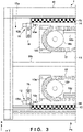
- Fig. 2 is a plan view of the base unit 1 seen through the cover 11 to show an internal space 10a of the frame body 10, and Figs. 3 and 4 are enlarged views of portions 1A and 1B in Fig. 2 .
- the pair of rail members 12 are plate-shaped members, which are extended in the Y direction and in parallel fixed to the frame body 10.
- the pair of rail members 12 form the travel path.
- the upper surface of each rail member 12 is exposed to the upper surface of the base unit 1.
- the moving unit 2 (traverser main body T) travels on the base unit 1.
- a gap 14 extending in the Y direction along the rail member 12 is formed.
- the internal space 10a surrounded by the cover 11 and the frame body 10 communicates with the external space above the base unit 1 via the gap 14.
- the passage members 16 are tilting plates arranged on both sides of the frame body 10 in the X direction.
- the passage members 16 form steps used by an operator to cross the base unit 1.
- the passage members 16 define a passage in the base unit 1, which is used by the operator to cross the base unit 1.
- Fig. 15 is a sectional view taken along a line C - C in Fig. 1B .
- the passage member 16 is extended from an installation surface (the floor surface in the factory) G on which the base unit 1 is installed to the upper surface of the rail member 12.
- the passage member 16 is formed by, for example, a steel plate, and includes a tilting portion 16a and a horizontal portion 16b. Since the tilting portion 16a is provided, the step difference between the frame body 10 and the installation surface G can be eliminated, and a smooth slope can be formed.
- the horizontal portion 16b is fixed to a constituent member 17 of the frame body 10. To fix the horizontal portion 16b to the constituent member 17, a screwing structure may be used, or a structure that engages engaging portions (for example, bent portions or concave and convex portions) provided on these may be employed.
- the frame body 10a defined by the frame body 10 also functions as a storage space for a cable 13 connected the moving unit 2.
- the internal space 10a is divided into two parts by a partition member 18c.
- the cable 13 includes at least a power cable used to supply power from an external electric circuit to a travel motor 271 of the moving unit 2.
- the cable 13 may also include a communication cable used for communication between a host device (not shown) and a control circuit 4.
- the cover 11 is a thin plate member that covers the internal space (storage space) 10a, and the cover 11 suppresses entry of dust and the like into the internal space 10a.
- the cable 13 is supported by a cable protection guide device (cable bear ® ) 17.
- two cable protection guide devices 17 in a laid state are provided in the frame body 10. If the cable 13 includes a power cable and a communication cable, one cable protection guide device 17 may support the power cable, and the other cable protection guide device 17 may support the communication cable. Note that a configuration that does not partition the internal space 10a by the partition member 18c can also be employed. In this case, one cable protection guide device 17 is provided. If the cable 13 includes a power cable and a communication cable, these cables may be supported by the one one cable protection guide device 17.
- Each cable protection guide device 17 is disposed to meander in the internal space 10a, and its movement is guided by a plurality of guides 18a provided in the frame body 10, the partition member 18c, and one roller 18b.
- the plurality of guides 18a include a linear member 18a-1, and an arc member 18a-2 around the roller 18b.
- the partition member 18c functions as a linear guide.
- One end 17a of the cable protection guide device 17 is connected to the moving unit 2 via a connecting tool (not shown) that passes through the gap 14, and the other end 17b is fixed to the frame body 10.
- One end 13a of the cable 13 is extended to the outside of the frame body 10 via the gap 14.
- the one end 13a is connected to the power supply unit (not shown) of the moving unit 2.
- the power supply unit supplies power to the travel motor 271 of a drive unit 25, a conveyance motor 371 of a drive unit 35, and the like.
- the other end 13b is connected to an external electric circuit (for example, a power supply device) (not shown) arranged outside the base unit 1.
- the one end 13a is connected to the control circuit 4 of the moving unit 2 via the gap 14.
- the control circuit 4 controls the travel motor 271 of the drive unit 25 and the conveyance motor 371 of the drive unit 35.
- the other end 13b is connected to a host device (for example, a PLC) (not shown) arranged outside the base unit 1.
- each of the rail members 12 in the frame body 10 are provided with stop members 15 that are brought into contact with the moving unit 2.
- Each stop member 15 is fixed to the frame body 10 via a support member 16.
- four stop members 15 are provided. Of these, the two stop members 15 shown in Fig. 3 stop the moving unit 2 (traverser main body T) at the stop position PI, and the remaining two stop members 15 shown in Fig. 4 stop the moving unit 2 at the stop position P2.
- each stop member 15 is a shock absorber that mitigates an impact when contacting the moving unit 2, and includes a rod 15a, and a cylinder 15b that stores the rod 15a such that it can freely move back and forth.
- the stop members 15 are arranged near the end portions of the rail members 12 while making the rods 15a face each other in the Y direction.
- the distal end of each rod 15a forms a contact portion that comes into contact with the moving unit 2, and is located near the lower portion of the gap 14.
- the cylinder 15b stores, for example, a spring that biases the rod 15a in a forward direction, a piston provided at an end portion of the rod 15a, and a liquid that resists the movement of the piston.
- the rod 15a moves backward in the cylinder 15b and mitigates the impact of contact.
- a solid member may be used.
- a shock absorber including a movable portion is used, as in this embodiment, the durability of the traverser 100 can be improved.
- Fig. 5 is a perspective view of the moving unit 2 viewed from the bottom surface side.
- the moving unit 2 includes two roller units 20 arranged in parallel while being apart in the X direction, and the drive unit 25 that is provided to connect the two roller units 20 and functions as the drive source of the moving unit 2.
- the two roller units 20 are connected by a plurality of connecting members 2b, and this holds the roller units 20 apart in parallel.
- Each roller unit 20 includes a roller array in which the travel roller 22 that is a drive roller and the plurality of travel rollers 23 that are driven rollers are arrayed along the moving direction (Y direction).
- the travel rollers 22 and 23 roll on the rail member 12, and this makes the moving unit 2 travel in the Y direction.
- Each roller unit 20 includes a support body (frame) 21 that supports the travel rollers 22 and 23 and mechanisms to be described later.
- the support body 21 includes a base plate 21a that forms the bottom portion of the roller unit 20 and extends in the Y direction, and support plates 21c provided at the front and rear ends of the base plate 21a in the Y direction.
- Each support plate 21c includes a stopper contact portion 29.
- the stopper contact portion 29 is a portion that contacts the stop member 15 at the stop position P1 or P2.
- the stopper contact portion 29 has an L shape including a support portion 29a extending downward in the Z direction from the lower surface of the support plate 21c, and a contact portion main body 29b extending from the lower end portion of the support portion 29a to the center of the roller unit 20.
- the support portion 29a moves along the gap 14, and the contact portion main body 29b contacts the rod 15a of the stop member 15.
- the lower surface of the support plate 21c also supports a rail contact portion 28 to be described later (see Fig. 6 ).
- Fig. 6 is a plan view of the moving unit 2 whose exterior portion is removed.
- the drive unit 25 includes a drive mechanism 27 supported by a support body (a frame; see Fig. 5 , not shown in Fig. 6 ) 26.
- the drive mechanism 27 is a mechanism configured to give a rotation driving force to the travel rollers 22 and 23, and includes the travel motor 271 that supplies the rotation driving force, a belt transmission mechanism 272, a drive shaft 273, a drive wheel 274, and a friction transmission mechanism FM.
- Fig. 7 is a longitudinal sectional view (a sectional view taken in the direction of arrows B in Fig. 6 ) of the moving unit 2 near the drive shaft 273.
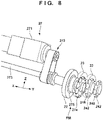
- Fig. 8 is a partial perspective view of the drive mechanism 27.
- the travel motor 271 is, for example, a DC motor, and includes a control board (not shown) configured to control the rotation direction and speed of the rotating shaft.
- the rotating shaft is supported, by the support body 26, above the drive shaft 273 and in parallel to the drive shaft 273.
- the control board includes, for example, a processor represented by a CPU, a storage device such as a RAM or a ROM, an input/output interface that relays between an external device and the processor, and a communication interface that performs communication with a host controller such as a PLC.
- the control board is arranged, for example, inside the housing of the travel motor 271 and connected to a power supply unit that supplies power to the travel motor 271 and the like.
- the control board outputs a control signal representing the rotation direction of the rotating shaft and a PWM (Pulse Width Modulation) signal representing the rotation speed, and controls the rotation of the rotating shaft of the travel motor 271.
- PWM Pulse Width Modulation
- a rotary encoder 41 is attached to the rotating shaft of the travel motor 271.
- the rotation amount of the rotating shaft detected by the rotary encoder 41 is input to the control board.
- control board stops outputting the control signal (CW or CCW signal) for instructing rotation of the travel motor 271. This stops the drive of the travel motor 271.
- the control board of the travel motor 271 stops the drive of the rotating shaft of the travel motor 271.
- the physical stop of the rotation of the rotating shaft of the travel motor 271 is detected using the rotary encoder.
- the physical stop of the rotation of the rotating shaft of the travel motor 271 may be detected using the current value of the control signal (CW or CCW signal) for instructing rotation.
- the current value of the control signal increases when the rotation of the rotating shaft is impeded.
- a current value when a load is applied to the rotating shaft of the rotating travel motor 271, and the rotation of the rotating shaft physically stops is set to a threshold. If it is detected that the current value of the control signal (CW or CCW signal) continuously exceeds the threshold for a predetermined time, the physical stop of the rotating shaft of the travel motor 271 can be detected.
- the travel motor 271 "stops the drive of the rotating shaft of the travel motor 271 if the rotation of the rotating shaft of the travel motor 271 is not detected for a predetermined time", as described above. Hence, even if the rotation of the rotating shaft of the travel motor 271 is physically stopped, the drive of the rotating shaft of the travel motor 271 is stopped upon detecting this.
- the belt transmission mechanism 272 transmits the rotation driving force of the travel motor 271 to the drive shaft 273 and rotates the drive shaft 273.
- the drive shaft 273 is a member extended in the X direction.
- a plurality of shafts are connected via shaft couplings to form one shaft as a whole.
- the support body 21 of each roller unit 20 includes a pair of support plates 21b that rotatably support the rotation center shafts of the travel rollers 22 and 23.
- the pair of support plates 21b are provided apart from each other at an arbitrary interval in the X direction and in parallel stand on the base plate 21a.
- the travel rollers 22 and 23 are arranged between the support plates 21b.
- the drive shaft 273 is rotatably and pivotally supported by the pair of support plates 21b located apart in the X direction.
- the travel roller 22 is provided between the pair of support plates 21b, and each travel roller 22 is attached to the drive shaft 273 via the friction transmission mechanism FM.
- the friction transmission mechanism FM is a mechanism configured to transmit the rotation driving force of the travel motor 271 to the travel roller 22 by a friction force, and includes a friction transmission member 275 in this embodiment.
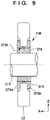
- Fig. 9 is a longitudinal sectional view of the travel roller 22.
- the friction transmission member 275 includes a pair of ring members that are provided on the peripheral surface of the drive shaft 273 and attach the travel roller 22 to the drive shaft 273.
- the friction transmission member 275 is formed by a pair of flanged bushes 275a and 275b fitted in the center hole of the travel roller 22.
- a bush 276 is provided on the peripheral surface of the drive shaft 273.
- the drive shaft 273 is fitted in the hole of the bush 276.
- the portion of the bush 276 on the drive shaft 273 is inserted into a hole 275h at the center of the friction transmission member 275, and the bush 276 is located in the hole 275h of the friction transmission member 275.
- the friction transmission member 275 and the bush 276 are not fixed. Transmission of the rotation driving force from the drive shaft 273 to the friction transmission member 275 is done by friction transmission. Hence, if an excessive load that resists the rotation of the travel roller 22 acts on the travel roller 22, idling (slip) occurs between the bush 276 provided on the drive shaft 273 and the friction transmission member 275.
- the drive shaft 273 continuously rotates, but the travel roller 22 stops rotating.
- the drive wheels 274 are provided at the two end portions of the drive shaft 273.
- the drive wheels 274 are fixed to the drive shaft 273 and rotate integrally with the drive shaft 273.
- the rotation driving force of each drive wheel 274 is transmitted to the travel rollers 23 via a travel transmission mechanism 24 provided in the roller unit 20.
- the travel transmission mechanism 24 includes drive shafts 241 of the travel rollers 23, the drive wheels 242 provided at the outer end portions of the drive shafts 241, and the driving force transmission member 246.
- the drive shafts 241 are provided in parallel to the drive shaft 273 and rotatably supported by the pair of support plates 21b.
- the drive wheel 242 is provided at one end of each drive shaft 241 (the end of the moving unit 2 on the outer side in the widthwise direction).
- one drive wheel 274 provided on the drive shaft 273, and the plurality of drive wheels 242 provided on the drive shafts 241 are arrayed in one line along the Y direction.
- the endless driving force transmission member 246 is wound around the drive wheels 274 and 242. Hence, along with the rotation of the drive shaft 273, the drive wheel 274 rotates, and the drive wheels 242 are rotated by the rotation of the drive wheel 274.
- the driving force transmission member 246 is a chain
- the drive wheels 274 and 242 are sprockets that mesh with the chain. These form a chain transmission mechanism.
- a belt transmission mechanism may be employed in place of the chain transmission mechanism.
- a gear mechanism in which the drive wheels 274 and 242 and the driving force transmission member 246 are made of gears may be employed.
- Fig. 10 is a longitudinal sectional view of the periphery of the travel roller 23.
- the travel roller 23 is formed integrally with the drive shaft 241, and the drive shaft 241 is supported by the pair of support plates 21b via a ball bearing.
- a transmitted portion 249 and a friction transmission member 244 are provided on the peripheral surface of the drive shaft 241.
- the transmitted portion 249 is a disc-shaped member provided in the middle of the drive shaft 241 and extending outward in the radial direction of the drive shaft 241.
- the transmitted portion 249 is fixed to the drive shaft 241 and rotates integrally with the drive shaft 241.
- the transmitted portion 249 and the drive shaft 241 may be formed as one member.
- the friction transmission member 244 is provided on the peripheral surface of the drive shaft 241 and intervenes between the drive wheel 242 and the drive shaft 241.
- the friction transmission member 244 is formed by a pair of flanged bushes.
- the flanged bushes are attached from both sides of the drive wheel 242 to cover both sides of the drive wheel 242 and the inner peripheral surface of the drive wheel 242.
- the friction transmission member 244 forms flange portions 244a whose end portions in the axial direction of the drive shaft 241 project in the radial direction.
- the drive wheel 242 is attached between the flange portions 244a, and the side surfaces of the drive wheel 242 and the flange portions 244a are in contact.
- One flange portion 244a is sandwiched between one side surface of the drive wheel 242 (the side surface on the side of the travel roller 23) and the transmitted portion 249.
- the friction transmission member 244 and the drive shaft 241 are not fixed. Transmission of the rotation driving force from the drive wheel 242 to the drive shaft 241 is done by friction transmission between the one side surface of the drive wheel 242 (the side surface on the side of the travel roller 23 (the left side in Fig. 10 )) and the transmitted portion 249 via the flange portion 244a.
- a biasing member 245 is provided.
- the biasing member 245 is a coil spring.
- another elastic member such as rubber may be used.
- the through hole 241a is a stepped hole whose diameter is small on the side of the drive wheel 242 and large on the opposite side (the side of the travel roller 23).
- a rod 247 is inserted in the through hole 241a.
- a pressing member 248 is fixed to one end portion of the rod 247 (the end portion on the side of the drive wheel 242), and a stopper portion 247a is formed at the other end portion.
- the biasing member 245 is interposed between the stopper portion 247a and the wall surface of the step portion of the through hole 241a.
- the pressing member 248 is a disc-shaped member that contacts the flange portion 244a on the opposite side of the friction transmission member 244 (the side not in contact with the transmitted portion 249).
- the rod 247 and the pressing member 248 are biased to the side of the travel roller 23. Accordingly, a sandwiching force for pressing the flange portion 244a on the side (the left side in Fig. 10 ) in contact with the transmitted portion 249 is generated between the one side surface of the drive wheel 242 (the side surface on the side of the travel roller 23) and the transmitted portion 249. Hence, the rotation driving force of the drive wheel 242 is frictionally transmitted to the drive shaft 241 via the flange portion 244a. If an excessive load that resists the rotation of the travel roller 23 acts on the travel roller 23, idling (slip) occurs between the drive shaft 241 and the friction transmission member 244. The drive wheel 242 continuously rotates, but the travel roller 23 stops rotating.
- the biasing member 245 is incorporated in the drive shaft 241.
- any other structure in which, for example, the biasing member 245 is arranged on the peripheral surface of the drive shaft 241 can also be employed. It is only necessary to bias the sandwiching force between the one side surface of the drive wheel 242 (the side surface on the side of the travel roller 23) and the transmitted portion 249.
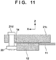
- Fig. 11 is a sectional view taken along a line A - A in Fig. 1A , and shows the arrangement of the rail contact portion 28 and peripheral components in a state in which the moving unit 2 is mounted on the base unit 1.
- the rail contact portion 28 is a roller arranged on the lower side of the support plate 21c.
- the support portion 21d is a shaft member extending in the vertical direction (Z direction). The upper end portion is fixed to the support plate 21c, and the rail contact portion 28 is rotatably supported on the lower end portion.
- the support portion 21d extends up to the lower side of the cover 11 via the gap 14.
- the rail contact portion 28 provided at the lower end of the support portion 21d contacts the side surface of the rail member 12 (in Fig. 11 , the left side surface or the inner side surface of each of the rail members 12 provided in parallel). Hence, the four rail contact portions 28 prevent the moving unit 2 from derailing from the rail members 12 when the moving unit 2 moves on the rail members 12.
- Fig. 12 is a plan view of the conveyance unit 3 whose exterior portion is removed.
- the conveyance unit 3 includes two roller units 30 arranged in parallel while being apart in the Y direction, and the drive unit 35 that is provided to connect the two roller units 30 and functions as the drive source of the conveyance unit 3.
- the two roller units 30 are connected by a plurality of connecting members 3a, and this holds the roller units 30 apart in parallel.
- the roller units 30 and the drive unit 35 have the same structures as the roller units 20 and the drive unit 25 except the number of rollers.
- the travel mechanism of the moving unit 2 and the conveyance mechanism of the conveyance unit 3 have the same structure. Hence, both can be formed using common components. This makes it possible to decrease the number of components of the traverser main body T and reduce the cost, and also facilitates component management.
- Each roller unit 30 includes a roller array in which the conveyance roller 32 that is a drive roller and the plurality of conveyance rollers 33 that are driven rollers are arrayed in one line (X direction). As the conveyance rollers 32 and 33 rotate, the conveyance target object W on these rollers is conveyed in the X direction. As the conveyance roller 32, the same roller as the travel roller 22 can be used. As the conveyance rollers 33, the same roller as the travel roller 23 can be used.
- Each roller unit 30 includes a support body (frame) 31 that supports the conveyance rollers 22 and 23 and mechanisms to be described later.
- the support body 31 has the same configuration as the support body 21 of the moving unit 2, and includes a base plate 31a that forms the bottom portion of the roller unit 30 and extends in the X direction, and a pair of support plates 31b.
- the support body 31 of the conveyance unit 3 does not have a configuration corresponding to the support plate 21c.
- the conveyance unit 3 does not have configurations corresponding to the contact portions 28 and 29 of the moving unit 2.
- the drive unit 35 includes a drive mechanism 37 supported by a support body (frame) 36.
- the drive mechanism 37 is a mechanism configured to give a rotation driving force to the conveyance rollers 32, and includes the conveyance motor 371 that supplies the rotation driving force, a belt transmission mechanism 372, a drive shaft 373, and a drive wheel 374.
- the drive mechanism 37 has the same configuration as the drive mechanism 27 and can use the same components.
- the conveyance motor 371 is, for example, a DC motor, and includes a control board (not shown) configured to control the rotation direction and speed of the rotating shaft.
- the rotating shaft is supported, by the support body 36, above the drive shaft 373 and in parallel to the drive shaft 373.
- the control board has the same configuration as the control board of the drive unit 25. If the rotation of the conveyance motor 371 stops for a predetermined time, the control board stops the conveyance motor 371.
- the belt transmission mechanism 372 transmits the rotation driving force of the conveyance motor 371 to the drive shaft 373 and rotates the drive shaft 373.
- the drive shaft 373 is a member extended in the Y direction. In this embodiment, a plurality of shafts are connected via shaft couplings to form one shaft as a whole.
- the support body 31 of each roller unit 30 includes a pair of support plates 21b that rotatably support the rotation center shafts of the conveyance rollers 22 and 23.
- the pair of support plates 21b are provided apart from each other at an arbitrary interval in the Y direction and in parallel stand on the base plate 31a.
- the conveyance rollers 32 and 33 are arranged between the support plates 31b.
- the drive shaft 373 is rotatably supported by the pair of support plates 21b located apart in the Y direction.
- the conveyance roller 32 is provided between the pair of support plates 21b, and each conveyance roller 32 is attached to the drive shaft 373 via a friction transmission member (not shown).
- the conveyance roller 32 is attached to the drive shaft 373 via a friction transmission member corresponding to the friction transmission member 275 and bushes (neither are shown).
- the drive wheels 374 are provided at the two end portions of the drive shaft 373.
- the drive wheels 374 are fixed to the drive shaft 373 and rotate integrally with the drive shaft 373.
- the rotation driving force of each drive wheel 374 is transmitted to the conveyance rollers 33 via a conveyance transmission mechanism 34 provided in the roller unit 30.
- the conveyance transmission mechanism 34 is the same mechanism as the travel transmission mechanism 24 except the number of rollers, and is a mechanism configured to transmit the rotation driving force of the drive wheels 374 to a drive wheel 342 of each conveyance roller 33 via a driving force transmission member 346.
- the mechanism of each conveyance roller 33 is also the same as the mechanism of each travel roller 23 shown in Fig. 10 .
- the same components can be used here as well.
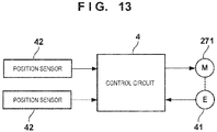
- Fig. 13 is a block diagram of the control system of the moving unit 2.
- the moving unit 2 includes the control circuit 4 that controls the travel motor 271.
- the rotary encoder 41 is attached to the drive shaft of the travel motor 271, and the rotation amount of the drive shaft detected by the rotary encoder 41 is input to the control circuit 4.
- the traverser 100 is provided with position sensors 42 configured to detect the position of the moving unit 2.
- the position sensors 42 according to this embodiment are provided at the two stop positions P1 and P2, respectively.
- One position sensor 42 detects whether the moving unit 2 exists at the stop position PI, and the other position sensor 42 detects whether the moving unit 2 exists at the stop position P2.
- Each position sensor 42 is, for example, a mechanical sensor that is turned on by contact with the moving unit 2 or an optical sensor such as a photointerrupter that optically detects the existence of the moving unit 2.
- the control circuit 4 is a microcomputer including, for example, a processor represented by a CPU, a storage device such as a RAM or a ROM, an input/output interface that relays between an external device and the processor, a communication interface that performs communication with a host controller, and the drive circuit of the travel motor 271.
- the control circuit 4 can be arranged, for example, inside the housing of the drive unit 25. To supply power to the travel motor 271 and the like, the cable 13 wired via the gap 14 is connected to the control circuit 4.
- Control of the conveyance unit 3 may be performed by the control circuit 4 or a control circuit provided in the conveyance unit 3.
- a rotary encoder may be provided on the conveyance motor 371 to detect the rotation amount of the drive shaft of the conveyance motor 371.
- the control circuit provided in the conveyance unit 3 may have the same configuration as the control circuit 4, and may be configured to communicate with the control circuit 4.
- the conveyance rollers and the travel rollers can have the same configuration, and the conveyance transmission mechanism and the travel transmission mechanism can have the same configuration, the manufacturing cost can be suppressed.
- the control circuit 4 moves the moving unit 2 from the stop position P1 to the stop position P2 or from the stop position P2 to the stop position P1 in accordance with an instruction of the host controller. More specifically, the control circuit 4 controls the rotation direction, the start and stop of rotation, and the rotation speed of the travel motor 271.
- the traverser main body T is moved from the stop position P1 to the stop position P2.
- the stopper contact portions 29 mechanically/physically contact the stop members 15. This impedes the movement of the traverser main body T, and the traverser main body T stops at the stop position P2.
- the travel motor 271, the drive shaft 273, the drive wheels 274, the driving force transmission members 246, and the drive wheels 242 continuously rotate, but the rotation of the travel rollers 22 and 23 stops.
- the conveyance target object W is transferred from the conveyor 62 on the unloading side to the conveyance unit 3.
- the traverser main body T moves from the stop position P2 to the stop position P1.
- the stopper contact portions 29 mechanically/physically contact the stop members 15. This impedes the movement of the traverser main body T, and the traverser main body T stops at the stop position P1.
- the travel motor 271, the drive shaft 273, the drive wheels 274, the driving force transmission members 246, and the drive wheels 242 continuously rotate, but the rotation of the travel rollers 22 and 23 stops.
- the conveyance target object W is transferred from the conveyance unit 3 to the conveyor 61 on the loading side.
- the traverser main body T moves from the stop position P1 to the stop position P2.
- the traverser 100 can convey the conveyance target object W between the conveyors 61 and 62.
- the stopper contact portions 29 mechanically/physically contact the stop members 15, thereby impeding the movement of the traverser main body T.
- the rotation driving force of the travel motor 271 is transmitted to the travel rollers 22 and 23 by friction transmission.
- the travel motor 271 continuously rotates, but the rotation of the travel rollers 22 and 23 stops. That is, the travel rollers 22 and 23 have an accumulate function (also called a free flow function).
- the traverser main body T can be stopped while keeping the travel motor 271 rotating, without separately providing a torque limiter or the like on the inverter control of the travel motor 271 or the drive shaft of the travel motor 271.
- the travel rollers 22 and 23 stop, but a force for moving forward continuously acts on the travel rollers 22 and 23.
- the travel rollers 22 and 23 never rotate in the direction (backward direction) opposite to the moving direction. That is, the travel rollers 22 and 23 (traverser main body T) are anti-back rollers and therefore never move backward.
- the traverser main body T continuously stops at the stop position P1 (or P2) where it contacts the stop members 15, and the correct positioning state at the stop position P1 (or P2) is held.
- the traverser main body T and the conveyors 61 and 62 need to be correctly positioned on a millimeter order.
- a positioning device for the traverser main body is prepared, and the traverser main body T is positioned at a stop position.
- a mechanism configured to fix the relative positional relationship between the traverser main body and a conveyor for example, a butting mechanism, a clamp mechanism, or the like is necessary, resulting in a large-scale apparatus configuration.
- the traverser main body T can be positioned at a correct position only by the configuration of the stop members 15 and the stopper contact portions 29. This obviates the necessity of the positioning device that is conventionally essential.
- the stopper contact portions 29 continue pressing the shock absorbers against the push back by the springs of the shock absorbers. For this reason, the traverser main body T is stopped while keeping the stopper contact portions 29 in contact with the shock absorbers. Hence, the traverser main body T can correctly be positioned at the stop position P1 (or P2) only by the shock absorbers.
- the rotation of the travel motor 271 is continued for a predetermined time until loading/unloading of the conveyance target object W ends.
- the travel motor 271 may be stopped.
- the rotation driving force is transmitted to the travel rollers 22 and 23 by friction transmission.
- the traverser main body T contacts an operator or the like halfway through the movement from the stop position P1 to P2 or from the stop position P2 to PI, and an overload more than the friction transmission force acts, the transmission of the rotation driving force to the travel rollers 22 and 23 is cut off, and the rotation of the travel rollers 22 and 23 stops.
- the traverser main body T if an overload more than the friction transmission force acts at the time of movement of the traverser main body T, the traverser main body T can be stopped safely and instantaneously even without providing auxiliary equipment such as a safety fence, a light curtain, or an area sensor.
- wired power supply using the cable 13 is used as power supply equipment to the moving unit 2.
- wireless power supply for supplying power from a unit on a power transmission side to a unit on a power reception side in a noncontact (wireless) state may be used.
- Fig. 14 is a view showing an example of a traverser 100 including a wireless power supply device 5.
- the wireless power supply device 5 includes power transmission units 51 provided on a base unit 1, a power reception unit 52 provided on a moving unit 2, and a power storage device 53 such as a battery or a capacitor.
- Each power transmission unit 51 is connected to an external electric circuit (for example, a power supply device) (not shown) and arranged such that when a traverser main body T stops at a stop position P1 or a stop position P2, the power transmission unit 51 and the power reception unit 52 are close and face each other (to supply power).
- an external electric circuit for example, a power supply device
- the power reception unit 52 is installed on a side surface of the moving unit 2 and electrically connected to the power storage device 53.
- This electrical connection can be either wired power supply or wireless power supply.
- the power storage device 53 may be provided independently of the power reception unit 52 but may be integrated with the power reception unit 52, as a matter of course.
- the power transmission unit 51 provided at the stop position P1 (or P2) supplies power to the power reception unit 52 by wireless power supply.
- the power reception unit 52 stores, in the power storage device 53, the power supplied from the power transmission unit 51. Using the power stored in the power storage device 53, a control circuit 4 drives a travel motor 271.
- the arrangement of the power reception unit 52, the power transmission unit 51, and the power storage device 53 in Fig. 14 is merely an example, and various arrangements can be employed.
- only one power transmission unit 51 may be provided.
- the power transmission unit 51 may be stored in an internal space 10a of the base unit 1.
- an electromagnetic induction method can suitably be used from the viewpoint of the transfer efficiency and the transmission distance.
- any one of a magnetic field resonance method, an electric field coupling method, and a radio wave reception method, which are generally used as a wireless power supply method, can be applied.
- a control circuit 4 may be arranged outside a moving unit 2.
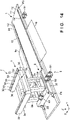
- Fig. 16 is a perspective view of a traverser 100 showing as an example
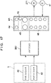
- Fig. 17 is a block diagram of a control system in the example shown in Fig. 16 .
- a communication unit 4A is provided as a control unit in place of the control circuit 4.
- the communication unit 4A includes a display unit 43, and is arranged such that an operator can visually recognize the display unit 43 from outside of the moving unit 2.
- the communication unit 4A is fixed to a support portion 30a on the outer wall portion of a conveyance unit 3 and exposed to the outside as a whole.
- the place to fix the communication unit 4A may be the outer wall portion of the moving unit 2.
- the communication unit 4A includes connectors 44 to 46.
- a communication cable that connects the communication unit 4A and a host device 200 is connected to the connector 44.
- a power supply cable that connects the communication unit 4A and an external power supply is connected to the connector 45.
- a control target device such as a travel motor 271 or a rotary encoder 41 is connected to the connector 46.
- the communication unit 4A includes, for example, a processor represented by a CPU, a storage device such as a RAM or a ROM, an input/output interface that relays between the control target device and the processor, and a communication interface that performs communication with a host controller. Note that the communication unit 4A may communicate with the host device 200 by wireless communication.
- the communication unit 4A receives an instruction from the host device 200 and controls drive of the travel motor 271. Note that the communication unit 4A may also control the conveyance unit 3.
- a detection signal from a position sensor 42 is input to the host device 200 via the communication unit 4A. Based on the detection signal from the position sensor 42, the host device 200 transmits an operation stop instruction or the like to the communication unit 4A. Based on the instruction from the host device 200 and the detection result of the rotary encoder 41, the communication unit 4A controls drive of the travel motor 271.
- the display unit 43 performs display concerning control of the travel motor 271.
- the display unit 43 is formed by a plurality of light-emitting elements. Each light-emitting element is provided, for example, for each connector of the communication unit 4A, and lights during transmission of a control signal from a corresponding connector to the control target device or the host device. Also, each light-emitting element is associated with a type of control signal from the host device 200 and lights during reception of a corresponding control instruction from the host device 200. The operator can confirm the display portion of the display unit 43 and confirm whether the operation of the moving unit 2 or the like is normally being performed.
Abstract
Description
- The present invention relates to a traverser.
- There is known a traverser that includes a conveyor on a mobile carriage and transfers a work between two points (for example, PTL 1). This traverser moves between two points including the downstream end of the conveyor located at one end portion of a moving path through which the mobile carriage moves and the upstream end of the conveyor located at the other end portion of the moving path and transfers a work.
- PTL 1:
Japanese Patent No. 462578 - If an operator or a foreign substance exists on the reciprocal moving path of the traverser, interference with the traverser may occur. At this time, the movement of the traverser may be impeded, and accordingly, an overload may act on the driving system of the traverser, resulting in damage to the traverser or the work. Hence, if such interference occurs, particularly, if contact with the operator occurs, the traverser is required to safely stop without auxiliary equipment as a sensor such as a safety fence or a light curtain.
- It is an object of the present invention to provide a traverser capable of safely stopping without auxiliary equipment at the time of overload action.
- According to the present invention, there is provided a traverser comprising: a base unit including a rail member; a moving unit configured to reciprocally move on the rail member between a first position and a second position; and a conveyance unit mounted on the moving unit and configured to convey a conveyance target object, wherein the moving unit comprises: a first travel roller that is a drive roller; and a drive mechanism configured to give a rotation driving force to the first travel roller, and the drive mechanism includes: a travel motor configured to supply the rotation driving force; and a friction transmission mechanism configured to transmit the rotation driving force of the travel motor to the first travel roller by a friction force.
- According to the present invention, it is possible to provide a traverser capable of safely stopping without auxiliary equipment at the time of overload action during movement.
-
-
Fig. 1A is a perspective view of a traverser according to an embodiment; -
Fig. 1B is a schematic plan view showing the use mode of the traverser according to the embodiment; -
Fig. 2 is a plan view of a base unit; -
Fig. 3 is an enlarged view of aportion 1A inFig. 2 ; -
Fig. 4 is an enlarged view of aportion 1B inFig. 2 ; -
Fig. 5 is a perspective view of a moving unit; -
Fig. 6 is an explanatory view of the drive system of the moving unit; -
Fig. 7 is an explanatory view of the drive system of the moving unit; -
Fig. 8 is a partial perspective view of the drive system of the moving unit; -
Fig. 9 is an explanatory view of the friction transmission structure of a travel roller; -
Fig. 10 is an explanatory view of the friction transmission structure of a travel roller; -
Fig. 11 is an explanatory view of the support structure of a contact portion corresponding to a sectional view taken along a line A - A inFig. 1A ; -
Fig. 12 is an explanatory view of the drive system of a conveyance unit; -
Fig. 13 is a block diagram of a control system; -
Fig. 14 is a view showing an example of wireless power supply; -
Fig. 15 is a sectional view taken along a line C - C inFig. 1B ; -
Fig. 16 is a view showing an example of the arrangement of a communication unit; and -
Fig. 17 is a block diagram of a control system in the example shown inFig. 16 . - Hereinafter, embodiments will be described in detail with reference to the attached drawings. Note that the following embodiments are not intended to limit the scope of the claimed invention, and limitation is not made an invention that requires all combinations of features described in the embodiments. Two or more of the multiple features described in the embodiments may be combined as appropriate. Furthermore, the same reference numerals are given to the same or similar configurations, and redundant description thereof is omitted.
-
Fig. 1A is a perspective view of atraverser 100 according to an embodiment of the present invention. In the drawings, an arrow X and an arrow Y indicate horizontal directions orthogonal to each other, and an arrow Z indicates a vertical direction to an X-Y plane. Thetraverser 100 includes abase unit 1, a movingunit 2, and aconveyance unit 3. The movingunit 2 and theconveyance unit 3 constitute a traverser main body T. Thebase unit 1 is extended in the Y direction and includes a travel path (rail member 12) for the traverser main body T (moving unit 2). The movingunit 2 is a travel unit that reciprocally moves on the travel path of thebase unit 1, and is stopped at stop positions P1 and P2 located at the two end portions of the travel path.Fig. 1 shows a state in which the movingunit 2 is located at the stop position P1. Theconveyance unit 3 is mounted on the movingunit 2 via a plurality ofcolumns 2a, and loads/unloads a conveyance target object W. In this embodiment, theconveyance unit 3 is a roller conveyor includingconveyance rollers - For example, as shown in
Fig. 1B , thetraverser 100 is used to transfer the conveyance target object W betweenconveyors unit 2 are provided in correspondence with the positions of theconveyors unit 2 stops at the stop position PI, the conveyor unit (to be described later) of theconveyance unit 3 faces the unload end (downstream end) of oneconveyor 61. In this state, delivery (transfer) of the conveyance target object W from the oneconveyor 61 to theconveyance unit 3 is performed. The traverser main body T to which the conveyance target object W is transferred moves along the travel path and stops at the stop position P2. At this time, the conveyor unit of theconveyance unit 3 faces the load end (upstream end) of theother conveyor 62. In this state, delivery of the conveyance target object W from theconveyance unit 3 to theother conveyor 62 is performed. Note that in this embodiment, theconveyance unit 3 conveys the conveyance target object W in the X direction. However, the conveyance target object W may be conveyed in a horizontal direction crossing the X direction. For example, the traverser main body T (moving unit 2) may be provided with a turn unit configured to change the direction of the conveyance target object W such thatconveyance unit 3 can rotate about the Z-axis. This can change the conveyance direction of theconveyance unit 3 in accordance with the tilt of the conveyance direction of theconveyors - The
base unit 1 includes a box-shapedframe body 10 opening upward, acover 11 that covers the opening of theframe body 10 and forms the upper surface of thebase unit 1, and a pair ofrail members 12 apart in the X direction. Thebase unit 1 also includespassage members 16.Fig. 2 is a plan view of thebase unit 1 seen through thecover 11 to show aninternal space 10a of theframe body 10, andFigs. 3 and4 are enlarged views ofportions Fig. 2 . - The pair of
rail members 12 are plate-shaped members, which are extended in the Y direction and in parallel fixed to theframe body 10. The pair ofrail members 12 form the travel path. The upper surface of eachrail member 12 is exposed to the upper surface of thebase unit 1. When thetravel rollers 22 and 23 (to be described later) of the movingunit 2 roll in contact with therail members 12, the moving unit 2 (traverser main body T) travels on thebase unit 1. Between thecover 11 and eachrail member 12, agap 14 extending in the Y direction along therail member 12 is formed. Theinternal space 10a surrounded by thecover 11 and theframe body 10 communicates with the external space above thebase unit 1 via thegap 14. - The
passage members 16 are tilting plates arranged on both sides of theframe body 10 in the X direction. Thepassage members 16 form steps used by an operator to cross thebase unit 1. In other words, thepassage members 16 define a passage in thebase unit 1, which is used by the operator to cross thebase unit 1. When thepassage members 16 are provided, an operator or a carriage can cross thebase unit 1 during stop of the movingunit 2, and the mobility of the operator in the factory where thetraverser 100 is installed can be improved. -
Fig. 15 is a sectional view taken along a line C - C inFig. 1B . Thepassage member 16 is extended from an installation surface (the floor surface in the factory) G on which thebase unit 1 is installed to the upper surface of therail member 12. Thepassage member 16 is formed by, for example, a steel plate, and includes a tiltingportion 16a and ahorizontal portion 16b. Since the tiltingportion 16a is provided, the step difference between theframe body 10 and the installation surface G can be eliminated, and a smooth slope can be formed. Thehorizontal portion 16b is fixed to aconstituent member 17 of theframe body 10. To fix thehorizontal portion 16b to theconstituent member 17, a screwing structure may be used, or a structure that engages engaging portions (for example, bent portions or concave and convex portions) provided on these may be employed. - Referring back to
Figs. 3 and4 , theframe body 10a defined by theframe body 10 also functions as a storage space for acable 13 connected the movingunit 2. Theinternal space 10a is divided into two parts by apartition member 18c. - The
cable 13 includes at least a power cable used to supply power from an external electric circuit to atravel motor 271 of the movingunit 2. Thecable 13 may also include a communication cable used for communication between a host device (not shown) and acontrol circuit 4. Thecover 11 is a thin plate member that covers the internal space (storage space) 10a, and thecover 11 suppresses entry of dust and the like into theinternal space 10a. Thecable 13 is supported by a cable protection guide device (cable bear®) 17. - In this embodiment, two cable
protection guide devices 17 in a laid state are provided in theframe body 10. If thecable 13 includes a power cable and a communication cable, one cableprotection guide device 17 may support the power cable, and the other cableprotection guide device 17 may support the communication cable. Note that a configuration that does not partition theinternal space 10a by thepartition member 18c can also be employed. In this case, one cableprotection guide device 17 is provided. If thecable 13 includes a power cable and a communication cable, these cables may be supported by the one one cableprotection guide device 17. - Each cable
protection guide device 17 is disposed to meander in theinternal space 10a, and its movement is guided by a plurality ofguides 18a provided in theframe body 10, thepartition member 18c, and oneroller 18b. The plurality ofguides 18a include alinear member 18a-1, and anarc member 18a-2 around theroller 18b. Thepartition member 18c functions as a linear guide. - One
end 17a of the cableprotection guide device 17 is connected to the movingunit 2 via a connecting tool (not shown) that passes through thegap 14, and theother end 17b is fixed to theframe body 10. Oneend 13a of thecable 13 is extended to the outside of theframe body 10 via thegap 14. - If the
cable 13 is a power cable, the oneend 13a is connected to the power supply unit (not shown) of the movingunit 2. The power supply unit supplies power to thetravel motor 271 of adrive unit 25, aconveyance motor 371 of adrive unit 35, and the like. Theother end 13b is connected to an external electric circuit (for example, a power supply device) (not shown) arranged outside thebase unit 1. - If the
cable 13 is a communication cable, the oneend 13a is connected to thecontrol circuit 4 of the movingunit 2 via thegap 14. Thecontrol circuit 4 controls thetravel motor 271 of thedrive unit 25 and theconveyance motor 371 of thedrive unit 35. Theother end 13b is connected to a host device (for example, a PLC) (not shown) arranged outside thebase unit 1. - When the
gap 14 is provided, it is possible to connect the movingunit 2 and theinternal space 10a of thebase unit 1 while arranging the movingunit 2 on thebase unit 1. - The two end portions of each of the
rail members 12 in theframe body 10 are provided withstop members 15 that are brought into contact with the movingunit 2. Eachstop member 15 is fixed to theframe body 10 via asupport member 16. In this embodiment, fourstop members 15 are provided. Of these, the twostop members 15 shown inFig. 3 stop the moving unit 2 (traverser main body T) at the stop position PI, and the remaining twostop members 15 shown inFig. 4 stop the movingunit 2 at the stop position P2. - In this embodiment, each
stop member 15 is a shock absorber that mitigates an impact when contacting the movingunit 2, and includes arod 15a, and acylinder 15b that stores therod 15a such that it can freely move back and forth. Thestop members 15 are arranged near the end portions of therail members 12 while making therods 15a face each other in the Y direction. The distal end of eachrod 15a forms a contact portion that comes into contact with the movingunit 2, and is located near the lower portion of thegap 14. Thecylinder 15b stores, for example, a spring that biases therod 15a in a forward direction, a piston provided at an end portion of therod 15a, and a liquid that resists the movement of the piston. When the movingunit 2 contacts therod 15a, therod 15a moves backward in thecylinder 15b and mitigates the impact of contact. As thestop member 15, a solid member may be used. However, when a shock absorber including a movable portion is used, as in this embodiment, the durability of thetraverser 100 can be improved. - The outline of the moving
unit 2 will be described with reference toFigs. 1A and5. Fig. 5 is a perspective view of the movingunit 2 viewed from the bottom surface side. The movingunit 2 includes tworoller units 20 arranged in parallel while being apart in the X direction, and thedrive unit 25 that is provided to connect the tworoller units 20 and functions as the drive source of the movingunit 2. The tworoller units 20 are connected by a plurality of connectingmembers 2b, and this holds theroller units 20 apart in parallel. - Each
roller unit 20 includes a roller array in which thetravel roller 22 that is a drive roller and the plurality oftravel rollers 23 that are driven rollers are arrayed along the moving direction (Y direction). Thetravel rollers rail member 12, and this makes the movingunit 2 travel in the Y direction. Eachroller unit 20 includes a support body (frame) 21 that supports thetravel rollers support body 21 includes abase plate 21a that forms the bottom portion of theroller unit 20 and extends in the Y direction, andsupport plates 21c provided at the front and rear ends of thebase plate 21a in the Y direction. - Each
support plate 21c includes astopper contact portion 29. Thestopper contact portion 29 is a portion that contacts thestop member 15 at the stop position P1 or P2. Thestopper contact portion 29 has an L shape including asupport portion 29a extending downward in the Z direction from the lower surface of thesupport plate 21c, and a contact portionmain body 29b extending from the lower end portion of thesupport portion 29a to the center of theroller unit 20. Along with the travel of the movingunit 2, thesupport portion 29a moves along thegap 14, and the contact portionmain body 29b contacts therod 15a of thestop member 15. In addition, the lower surface of thesupport plate 21c also supports arail contact portion 28 to be described later (seeFig. 6 ). - The configuration of the drive system of the moving
unit 2 will be described with reference toFigs. 5 to 8 .Fig. 6 is a plan view of the movingunit 2 whose exterior portion is removed. Thedrive unit 25 includes adrive mechanism 27 supported by a support body (a frame; seeFig. 5 , not shown inFig. 6 ) 26. Thedrive mechanism 27 is a mechanism configured to give a rotation driving force to thetravel rollers travel motor 271 that supplies the rotation driving force, abelt transmission mechanism 272, adrive shaft 273, adrive wheel 274, and a friction transmission mechanism FM.Fig. 7 is a longitudinal sectional view (a sectional view taken in the direction of arrows B inFig. 6 ) of the movingunit 2 near thedrive shaft 273.Fig. 8 is a partial perspective view of thedrive mechanism 27. - The
travel motor 271 is, for example, a DC motor, and includes a control board (not shown) configured to control the rotation direction and speed of the rotating shaft. The rotating shaft is supported, by thesupport body 26, above thedrive shaft 273 and in parallel to thedrive shaft 273. - The control board includes, for example, a processor represented by a CPU, a storage device such as a RAM or a ROM, an input/output interface that relays between an external device and the processor, and a communication interface that performs communication with a host controller such as a PLC. The control board is arranged, for example, inside the housing of the
travel motor 271 and connected to a power supply unit that supplies power to thetravel motor 271 and the like. - The control board outputs a control signal representing the rotation direction of the rotating shaft and a PWM (Pulse Width Modulation) signal representing the rotation speed, and controls the rotation of the rotating shaft of the
travel motor 271. - In addition, a
rotary encoder 41 is attached to the rotating shaft of thetravel motor 271. The rotation amount of the rotating shaft detected by therotary encoder 41 is input to the control board. - If the output signal of the
rotary encoder 41 does not change for a predetermined time, the control board stops outputting the control signal (CW or CCW signal) for instructing rotation of thetravel motor 271. This stops the drive of thetravel motor 271. - In this way, if the rotation of the rotating shaft of the
travel motor 271 is not detected for a predetermined time, the control board of thetravel motor 271 stops the drive of the rotating shaft of thetravel motor 271. - In the above-described method, the physical stop of the rotation of the rotating shaft of the
travel motor 271 is detected using the rotary encoder. However, the physical stop of the rotation of the rotating shaft of thetravel motor 271 may be detected using the current value of the control signal (CW or CCW signal) for instructing rotation. - For example, the current value of the control signal (CW or CCW signal) increases when the rotation of the rotating shaft is impeded. Hence, a current value when a load is applied to the rotating shaft of the
rotating travel motor 271, and the rotation of the rotating shaft physically stops is set to a threshold. If it is detected that the current value of the control signal (CW or CCW signal) continuously exceeds the threshold for a predetermined time, the physical stop of the rotating shaft of thetravel motor 271 can be detected. - When the rotation of the rotating shaft of the
travel motor 271 is physically stopped, the drive of the rotating shaft is stopped. The rotation of the rotating shaft is physically stopped when, for example, a foreign substance such as a bolt or a screw is fallen in thegap 14 and caught between adrive wheel drive transmission member 246 or between thedrive wheel support plate 21b. At this time, the rotation of thedrive wheel drive transmission member 246 is impeded. - Here, in a case in which a general-purpose motor is used as the
travel motor 271, even if the rotation of thedrive wheel drive transmission member 246 is impeded, and the rotating shaft of the motor physically stops, the motor continuously rotates. As a result, the rotating shaft that cannot physically rotate is forcibly continuously rotated by the motor. In the worst case, the motor fails or breaks. - On the other hand, in the
traverser 100 according to this embodiment, if the rotation of thedrive wheel drive transmission member 246 is impeded by a foreign substance, the rotation of thedrive shaft 273 and the travel of thebelt transmission mechanism 272 stop. However, in thetraverser 100 according to this embodiment, thetravel motor 271 "stops the drive of the rotating shaft of thetravel motor 271 if the rotation of the rotating shaft of thetravel motor 271 is not detected for a predetermined time", as described above. Hence, even if the rotation of the rotating shaft of thetravel motor 271 is physically stopped, the drive of the rotating shaft of thetravel motor 271 is stopped upon detecting this. That is, if the rotating shaft of thetravel motor 271 is physically stopped, the drive of the] rotating shaft of thetravel motor 271 is stopped upon detecting this. For this reason, thetravel motor 271 never forcibly continuously rotates the rotating shaft that cannot rotate. As a result, a failure or breakage of thetravel motor 271 never occurs due to the foreign substance, and the drive of the rotating shaft of thetravel motor 271 is safely stopped. - The
belt transmission mechanism 272 transmits the rotation driving force of thetravel motor 271 to thedrive shaft 273 and rotates thedrive shaft 273. Thedrive shaft 273 is a member extended in the X direction. In this embodiment, a plurality of shafts are connected via shaft couplings to form one shaft as a whole. Thesupport body 21 of eachroller unit 20 includes a pair ofsupport plates 21b that rotatably support the rotation center shafts of thetravel rollers support plates 21b are provided apart from each other at an arbitrary interval in the X direction and in parallel stand on thebase plate 21a. Thetravel rollers support plates 21b. - The
drive shaft 273 is rotatably and pivotally supported by the pair ofsupport plates 21b located apart in the X direction. Thetravel roller 22 is provided between the pair ofsupport plates 21b, and eachtravel roller 22 is attached to thedrive shaft 273 via the friction transmission mechanism FM. The friction transmission mechanism FM is a mechanism configured to transmit the rotation driving force of thetravel motor 271 to thetravel roller 22 by a friction force, and includes afriction transmission member 275 in this embodiment. -
Fig. 9 is a longitudinal sectional view of thetravel roller 22. Thefriction transmission member 275 includes a pair of ring members that are provided on the peripheral surface of thedrive shaft 273 and attach thetravel roller 22 to thedrive shaft 273. In this embodiment, thefriction transmission member 275 is formed by a pair offlanged bushes travel roller 22. In the contact portion between thedrive shaft 273 and thefriction transmission member 275, abush 276 is provided on the peripheral surface of thedrive shaft 273. For example, thedrive shaft 273 is fitted in the hole of thebush 276. The portion of thebush 276 on thedrive shaft 273 is inserted into ahole 275h at the center of thefriction transmission member 275, and thebush 276 is located in thehole 275h of thefriction transmission member 275. Thefriction transmission member 275 and thebush 276 are not fixed. Transmission of the rotation driving force from thedrive shaft 273 to thefriction transmission member 275 is done by friction transmission. Hence, if an excessive load that resists the rotation of thetravel roller 22 acts on thetravel roller 22, idling (slip) occurs between thebush 276 provided on thedrive shaft 273 and thefriction transmission member 275. Thedrive shaft 273 continuously rotates, but thetravel roller 22 stops rotating. - Referring back to
Figs. 5 to 8 , thedrive wheels 274 are provided at the two end portions of thedrive shaft 273. Thedrive wheels 274 are fixed to thedrive shaft 273 and rotate integrally with thedrive shaft 273. The rotation driving force of eachdrive wheel 274 is transmitted to thetravel rollers 23 via atravel transmission mechanism 24 provided in theroller unit 20. - The
travel transmission mechanism 24 includesdrive shafts 241 of thetravel rollers 23, thedrive wheels 242 provided at the outer end portions of thedrive shafts 241, and the drivingforce transmission member 246. Thedrive shafts 241 are provided in parallel to thedrive shaft 273 and rotatably supported by the pair ofsupport plates 21b. Thedrive wheel 242 is provided at one end of each drive shaft 241 (the end of the movingunit 2 on the outer side in the widthwise direction). In eachroller unit 20, onedrive wheel 274 provided on thedrive shaft 273, and the plurality ofdrive wheels 242 provided on thedrive shafts 241 are arrayed in one line along the Y direction. The endless drivingforce transmission member 246 is wound around thedrive wheels drive shaft 273, thedrive wheel 274 rotates, and thedrive wheels 242 are rotated by the rotation of thedrive wheel 274. - In this embodiment, the driving
force transmission member 246 is a chain, and thedrive wheels drive wheels force transmission member 246 are made of gears may be employed. - Of the configuration of the
travel transmission mechanism 24, the configuration for eachtravel roller 23 will further be described with reference toFig. 10. Fig. 10 is a longitudinal sectional view of the periphery of thetravel roller 23. In this embodiment, thetravel roller 23 is formed integrally with thedrive shaft 241, and thedrive shaft 241 is supported by the pair ofsupport plates 21b via a ball bearing. - A transmitted
portion 249 and afriction transmission member 244 are provided on the peripheral surface of thedrive shaft 241. The transmittedportion 249 is a disc-shaped member provided in the middle of thedrive shaft 241 and extending outward in the radial direction of thedrive shaft 241. The transmittedportion 249 is fixed to thedrive shaft 241 and rotates integrally with thedrive shaft 241. The transmittedportion 249 and thedrive shaft 241 may be formed as one member. - The
friction transmission member 244 is provided on the peripheral surface of thedrive shaft 241 and intervenes between thedrive wheel 242 and thedrive shaft 241. Thefriction transmission member 244 is formed by a pair of flanged bushes. The flanged bushes are attached from both sides of thedrive wheel 242 to cover both sides of thedrive wheel 242 and the inner peripheral surface of thedrive wheel 242. In this embodiment, thefriction transmission member 244 forms flangeportions 244a whose end portions in the axial direction of thedrive shaft 241 project in the radial direction. Thedrive wheel 242 is attached between theflange portions 244a, and the side surfaces of thedrive wheel 242 and theflange portions 244a are in contact. Oneflange portion 244a is sandwiched between one side surface of the drive wheel 242 (the side surface on the side of the travel roller 23) and the transmittedportion 249. Thefriction transmission member 244 and thedrive shaft 241 are not fixed. Transmission of the rotation driving force from thedrive wheel 242 to thedrive shaft 241 is done by friction transmission between the one side surface of the drive wheel 242 (the side surface on the side of the travel roller 23 (the left side inFig. 10 )) and the transmittedportion 249 via theflange portion 244a. - To bias the sandwiching force of the
flange portion 244a between the one side surface of the drive wheel 242 (the side surface on the side of the travel roller 23) and the transmittedportion 249, a biasingmember 245 is provided. In this embodiment, the biasingmember 245 is a coil spring. However, another elastic member such as rubber may be used. In thedrive shaft 241, a through hole 241a that is concentric with thedrive shaft 241 and extends through thedrive shaft 241 in the axial direction is formed. The through hole 241a is a stepped hole whose diameter is small on the side of thedrive wheel 242 and large on the opposite side (the side of the travel roller 23). - A
rod 247 is inserted in the through hole 241a. Apressing member 248 is fixed to one end portion of the rod 247 (the end portion on the side of the drive wheel 242), and astopper portion 247a is formed at the other end portion. The biasingmember 245 is interposed between thestopper portion 247a and the wall surface of the step portion of the through hole 241a. The pressingmember 248 is a disc-shaped member that contacts theflange portion 244a on the opposite side of the friction transmission member 244 (the side not in contact with the transmitted portion 249). - By biasing of the biasing
member 245, therod 247 and thepressing member 248 are biased to the side of thetravel roller 23. Accordingly, a sandwiching force for pressing theflange portion 244a on the side (the left side inFig. 10 ) in contact with the transmittedportion 249 is generated between the one side surface of the drive wheel 242 (the side surface on the side of the travel roller 23) and the transmittedportion 249. Hence, the rotation driving force of thedrive wheel 242 is frictionally transmitted to thedrive shaft 241 via theflange portion 244a. If an excessive load that resists the rotation of thetravel roller 23 acts on thetravel roller 23, idling (slip) occurs between thedrive shaft 241 and thefriction transmission member 244. Thedrive wheel 242 continuously rotates, but thetravel roller 23 stops rotating. - Note that in this embodiment, the biasing
member 245 is incorporated in thedrive shaft 241. However, any other structure in which, for example, the biasingmember 245 is arranged on the peripheral surface of thedrive shaft 241 can also be employed. It is only necessary to bias the sandwiching force between the one side surface of the drive wheel 242 (the side surface on the side of the travel roller 23) and the transmittedportion 249. - Referring to
Fig. 6 , therail contact portion 28 is supported on eachsupport plate 21c via asupport portion 21d.Fig. 11 is a sectional view taken along a line A - A inFig. 1A , and shows the arrangement of therail contact portion 28 and peripheral components in a state in which the movingunit 2 is mounted on thebase unit 1. Therail contact portion 28 is a roller arranged on the lower side of thesupport plate 21c. Thesupport portion 21d is a shaft member extending in the vertical direction (Z direction). The upper end portion is fixed to thesupport plate 21c, and therail contact portion 28 is rotatably supported on the lower end portion. Thesupport portion 21d extends up to the lower side of thecover 11 via thegap 14. Therail contact portion 28 provided at the lower end of thesupport portion 21d contacts the side surface of the rail member 12 (inFig. 11 , the left side surface or the inner side surface of each of therail members 12 provided in parallel). Hence, the fourrail contact portions 28 prevent the movingunit 2 from derailing from therail members 12 when the movingunit 2 moves on therail members 12. - The configuration of the
conveyance unit 3 will be described with reference toFigs. 1A and12. Fig. 12 is a plan view of theconveyance unit 3 whose exterior portion is removed. Theconveyance unit 3 includes tworoller units 30 arranged in parallel while being apart in the Y direction, and thedrive unit 35 that is provided to connect the tworoller units 30 and functions as the drive source of theconveyance unit 3. The tworoller units 30 are connected by a plurality of connectingmembers 3a, and this holds theroller units 30 apart in parallel. - Concerning the drive mechanism, the
roller units 30 and thedrive unit 35 have the same structures as theroller units 20 and thedrive unit 25 except the number of rollers. In other words, the travel mechanism of the movingunit 2 and the conveyance mechanism of theconveyance unit 3 have the same structure. Hence, both can be formed using common components. This makes it possible to decrease the number of components of the traverser main body T and reduce the cost, and also facilitates component management. - Each
roller unit 30 includes a roller array in which theconveyance roller 32 that is a drive roller and the plurality ofconveyance rollers 33 that are driven rollers are arrayed in one line (X direction). As theconveyance rollers conveyance roller 32, the same roller as thetravel roller 22 can be used. As theconveyance rollers 33, the same roller as thetravel roller 23 can be used. - Each
roller unit 30 includes a support body (frame) 31 that supports theconveyance rollers support body 31 has the same configuration as thesupport body 21 of the movingunit 2, and includes abase plate 31a that forms the bottom portion of theroller unit 30 and extends in the X direction, and a pair ofsupport plates 31b. On the other hand, unlike thesupport body 21 of the moving unit, thesupport body 31 of theconveyance unit 3 does not have a configuration corresponding to thesupport plate 21c. Also, theconveyance unit 3 does not have configurations corresponding to thecontact portions unit 2. - The
drive unit 35 includes adrive mechanism 37 supported by a support body (frame) 36. Thedrive mechanism 37 is a mechanism configured to give a rotation driving force to theconveyance rollers 32, and includes theconveyance motor 371 that supplies the rotation driving force, abelt transmission mechanism 372, adrive shaft 373, and adrive wheel 374. Thedrive mechanism 37 has the same configuration as thedrive mechanism 27 and can use the same components. - The
conveyance motor 371 is, for example, a DC motor, and includes a control board (not shown) configured to control the rotation direction and speed of the rotating shaft. The rotating shaft is supported, by thesupport body 36, above thedrive shaft 373 and in parallel to thedrive shaft 373. Here, the control board has the same configuration as the control board of thedrive unit 25. If the rotation of theconveyance motor 371 stops for a predetermined time, the control board stops theconveyance motor 371. Thebelt transmission mechanism 372 transmits the rotation driving force of theconveyance motor 371 to thedrive shaft 373 and rotates thedrive shaft 373. Thedrive shaft 373 is a member extended in the Y direction. In this embodiment, a plurality of shafts are connected via shaft couplings to form one shaft as a whole. Thesupport body 31 of eachroller unit 30 includes a pair ofsupport plates 21b that rotatably support the rotation center shafts of theconveyance rollers support plates 21b are provided apart from each other at an arbitrary interval in the Y direction and in parallel stand on thebase plate 31a. Theconveyance rollers support plates 31b. - The
drive shaft 373 is rotatably supported by the pair ofsupport plates 21b located apart in the Y direction. Theconveyance roller 32 is provided between the pair ofsupport plates 21b, and eachconveyance roller 32 is attached to thedrive shaft 373 via a friction transmission member (not shown). Like thetravel roller 22 of the movingunit 2, theconveyance roller 32 is attached to thedrive shaft 373 via a friction transmission member corresponding to thefriction transmission member 275 and bushes (neither are shown). Hence, if an excessive load that resists the rotation of theconveyance roller 32 acts on theconveyance roller 32, idling (slip) occurs between the bushes provided on thedrive shaft 373 and the friction transmission member. Thedrive shaft 373 continuously rotates, but theconveyance roller 32 stops rotating. - The
drive wheels 374 are provided at the two end portions of thedrive shaft 373. Thedrive wheels 374 are fixed to thedrive shaft 373 and rotate integrally with thedrive shaft 373. The rotation driving force of eachdrive wheel 374 is transmitted to theconveyance rollers 33 via aconveyance transmission mechanism 34 provided in theroller unit 30. - The
conveyance transmission mechanism 34 is the same mechanism as thetravel transmission mechanism 24 except the number of rollers, and is a mechanism configured to transmit the rotation driving force of thedrive wheels 374 to adrive wheel 342 of eachconveyance roller 33 via a drivingforce transmission member 346. The mechanism of eachconveyance roller 33 is also the same as the mechanism of eachtravel roller 23 shown inFig. 10 . The same components can be used here as well. -
Fig. 13 is a block diagram of the control system of the movingunit 2. The movingunit 2 includes thecontrol circuit 4 that controls thetravel motor 271. Therotary encoder 41 is attached to the drive shaft of thetravel motor 271, and the rotation amount of the drive shaft detected by therotary encoder 41 is input to thecontrol circuit 4. Also, thetraverser 100 is provided withposition sensors 42 configured to detect the position of the movingunit 2. Theposition sensors 42 according to this embodiment are provided at the two stop positions P1 and P2, respectively. Oneposition sensor 42 detects whether the movingunit 2 exists at the stop position PI, and theother position sensor 42 detects whether the movingunit 2 exists at the stop position P2. Eachposition sensor 42 is, for example, a mechanical sensor that is turned on by contact with the movingunit 2 or an optical sensor such as a photointerrupter that optically detects the existence of the movingunit 2. - The
control circuit 4 is a microcomputer including, for example, a processor represented by a CPU, a storage device such as a RAM or a ROM, an input/output interface that relays between an external device and the processor, a communication interface that performs communication with a host controller, and the drive circuit of thetravel motor 271. Thecontrol circuit 4 can be arranged, for example, inside the housing of thedrive unit 25. To supply power to thetravel motor 271 and the like, thecable 13 wired via thegap 14 is connected to thecontrol circuit 4. - Control of the
conveyance unit 3 may be performed by thecontrol circuit 4 or a control circuit provided in theconveyance unit 3. Like thetravel motor 271, a rotary encoder may be provided on theconveyance motor 371 to detect the rotation amount of the drive shaft of theconveyance motor 371. The control circuit provided in theconveyance unit 3 may have the same configuration as thecontrol circuit 4, and may be configured to communicate with thecontrol circuit 4. - As described above, since the conveyance rollers and the travel rollers can have the same configuration, and the conveyance transmission mechanism and the travel transmission mechanism can have the same configuration, the manufacturing cost can be suppressed.
- An example of control of the moving
unit 2 by thecontrol circuit 4 will be described. Thecontrol circuit 4 moves the movingunit 2 from the stop position P1 to the stop position P2 or from the stop position P2 to the stop position P1 in accordance with an instruction of the host controller. More specifically, thecontrol circuit 4 controls the rotation direction, the start and stop of rotation, and the rotation speed of thetravel motor 271. - First, the traverser main body T is moved from the stop position P1 to the stop position P2. When the traverser main body T reaches the stop position P2, the
stopper contact portions 29 mechanically/physically contact thestop members 15. This impedes the movement of the traverser main body T, and the traverser main body T stops at the stop position P2. - At this time, the
travel motor 271, thedrive shaft 273, thedrive wheels 274, the drivingforce transmission members 246, and thedrive wheels 242 continuously rotate, but the rotation of thetravel rollers - After the
position sensor 42 detects that the movingunit 2 reaches the stop position P2, the conveyance target object W is transferred from theconveyor 62 on the unloading side to theconveyance unit 3. - After a predetermined time elapses from the start of the movement of the traverser main body T from the stop position P1 to the stop position P2, and it is confirmed that the
conveyance unit 3 is not performing the transfer operation of the conveyance target object W, the traverser main body T moves from the stop position P2 to the stop position P1. - When the traverser main body T reaches the stop position PI, the
stopper contact portions 29 mechanically/physically contact thestop members 15. This impedes the movement of the traverser main body T, and the traverser main body T stops at the stop position P1. - At this time, the
travel motor 271, thedrive shaft 273, thedrive wheels 274, the drivingforce transmission members 246, and thedrive wheels 242 continuously rotate, but the rotation of thetravel rollers - After the
position sensor 42 detects that the movingunit 2 reaches the stop position PI, the conveyance target object W is transferred from theconveyance unit 3 to theconveyor 61 on the loading side. - After a predetermined time elapses from the start of the movement of the traverser main body T from the stop position P2 to the stop position PI, and it is confirmed that the
conveyance unit 3 is not performing the transfer operation of the conveyance target object W, the traverser main body T moves from the stop position P1 to the stop position P2. - By repeating these operations, the
traverser 100 can convey the conveyance target object W between theconveyors - In addition, when stopping the traverser main body T at the stop position P1 or P2, the
stopper contact portions 29 mechanically/physically contact thestop members 15, thereby impeding the movement of the traverser main body T. - Here, the rotation driving force of the
travel motor 271 is transmitted to thetravel rollers unit 2 is impeded by the mechanical/physical contact between thestop members 15 and thestopper contact portions 29, and an overload more than the friction transmission force acts, slip occurs between thefriction transmission member 275 and thebush 276 and between thefriction transmission member 244 and thetravel rollers 23. Hence, thetravel motor 271 continuously rotates, but the rotation of thetravel rollers travel rollers - For this reason, in the
traverser 100 according to this embodiment, the traverser main body T can be stopped while keeping thetravel motor 271 rotating, without separately providing a torque limiter or the like on the inverter control of thetravel motor 271 or the drive shaft of thetravel motor 271. - Even during the occurrence of the above-described slip, the friction between the
friction transmission member 275 and thebush 276 and between thefriction transmission member 244 and thetravel roller 23 is not zero, and friction occurs. - Hence, even during the occurrence of the slip, by friction, a force for rotating in the moving direction (forward direction) of the traverser main body T acts on the
travel rollers friction transmission member 275 and thebush 276 and between thefriction transmission member 244 and thetravel roller 23. - For this reason, the apparent rotation of the
travel rollers travel rollers travel rollers travel rollers 22 and 23 (traverser main body T) are anti-back rollers and therefore never move backward. Hence, the traverser main body T continuously stops at the stop position P1 (or P2) where it contacts thestop members 15, and the correct positioning state at the stop position P1 (or P2) is held. - When loading/unloading the conveyance target object W, the traverser main body T and the
conveyors - On the other hand, in the
traverser 100 according to this embodiment, using thetravel rollers stop members 15 and thestopper contact portions 29. This obviates the necessity of the positioning device that is conventionally essential. - Also, even if shock absorbers are used as the
stop members 15, when thetravel rollers stopper contact portions 29 continue pressing the shock absorbers against the push back by the springs of the shock absorbers. For this reason, the traverser main body T is stopped while keeping thestopper contact portions 29 in contact with the shock absorbers. Hence, the traverser main body T can correctly be positioned at the stop position P1 (or P2) only by the shock absorbers. - Also, after the
position sensor 42 detects that the movingunit 2 reaches the stop position P1 (or P2), the rotation of thetravel motor 271 is continued for a predetermined time until loading/unloading of the conveyance target object W ends. When it is confirmed that theconveyance unit 3 is not performing the conveyance operation of transfer of the conveyance target object W, thetravel motor 271 may be stopped. - The rotation driving force is transmitted to the
travel rollers travel rollers travel rollers traverser 100 according to this embodiment, if an overload more than the friction transmission force acts at the time of movement of the traverser main body T, the traverser main body T can be stopped safely and instantaneously even without providing auxiliary equipment such as a safety fence, a light curtain, or an area sensor. - In the above-described embodiment, wired power supply using the
cable 13 is used as power supply equipment to the movingunit 2. However, wireless power supply for supplying power from a unit on a power transmission side to a unit on a power reception side in a noncontact (wireless) state may be used. -
Fig. 14 is a view showing an example of atraverser 100 including a wirelesspower supply device 5. As shown inFig. 14 , the wirelesspower supply device 5 includespower transmission units 51 provided on abase unit 1, apower reception unit 52 provided on a movingunit 2, and apower storage device 53 such as a battery or a capacitor. - Each
power transmission unit 51 is connected to an external electric circuit (for example, a power supply device) (not shown) and arranged such that when a traverser main body T stops at a stop position P1 or a stop position P2, thepower transmission unit 51 and thepower reception unit 52 are close and face each other (to supply power). - The
power reception unit 52 is installed on a side surface of the movingunit 2 and electrically connected to thepower storage device 53. This electrical connection can be either wired power supply or wireless power supply. Also, thepower storage device 53 may be provided independently of thepower reception unit 52 but may be integrated with thepower reception unit 52, as a matter of course. - In the wireless
power supply device 5, when the traverser main body T stops at the stop position P1 (or P2), thepower transmission unit 51 provided at the stop position P1 (or P2) supplies power to thepower reception unit 52 by wireless power supply. - The
power reception unit 52 stores, in thepower storage device 53, the power supplied from thepower transmission unit 51. Using the power stored in thepower storage device 53, acontrol circuit 4 drives atravel motor 271. - According to this embodiment, since a configuration associated with a
cable 13 is unnecessary, wiring and handling of a cable and the like are unnecessary, and the apparatus configuration becomes simple. - Note that the arrangement of the
power reception unit 52, thepower transmission unit 51, and thepower storage device 53 inFig. 14 is merely an example, and various arrangements can be employed. For example, only onepower transmission unit 51 may be provided. Also, thepower transmission unit 51 may be stored in aninternal space 10a of thebase unit 1. - As the wireless power supply method according to this embodiment, for example, an electromagnetic induction method can suitably be used from the viewpoint of the transfer efficiency and the transmission distance. In addition, any one of a magnetic field resonance method, an electric field coupling method, and a radio wave reception method, which are generally used as a wireless power supply method, can be applied.
- A
control circuit 4 may be arranged outside a movingunit 2.Fig. 16 is a perspective view of atraverser 100 showing as an example, andFig. 17 is a block diagram of a control system in the example shown inFig. 16 . - In the example shown in
Fig. 16 , acommunication unit 4A is provided as a control unit in place of thecontrol circuit 4. Thecommunication unit 4A includes adisplay unit 43, and is arranged such that an operator can visually recognize thedisplay unit 43 from outside of the movingunit 2. In the example shown inFig. 16 , thecommunication unit 4A is fixed to asupport portion 30a on the outer wall portion of aconveyance unit 3 and exposed to the outside as a whole. The place to fix thecommunication unit 4A may be the outer wall portion of the movingunit 2. - The
communication unit 4A includesconnectors 44 to 46. A communication cable that connects thecommunication unit 4A and ahost device 200 is connected to theconnector 44. A power supply cable that connects thecommunication unit 4A and an external power supply is connected to theconnector 45. A control target device such as atravel motor 271 or arotary encoder 41 is connected to theconnector 46. - The
communication unit 4A includes, for example, a processor represented by a CPU, a storage device such as a RAM or a ROM, an input/output interface that relays between the control target device and the processor, and a communication interface that performs communication with a host controller. Note that thecommunication unit 4A may communicate with thehost device 200 by wireless communication. - The
communication unit 4A receives an instruction from thehost device 200 and controls drive of thetravel motor 271. Note that thecommunication unit 4A may also control theconveyance unit 3. - In this embodiment, a detection signal from a
position sensor 42 is input to thehost device 200 via thecommunication unit 4A. Based on the detection signal from theposition sensor 42, thehost device 200 transmits an operation stop instruction or the like to thecommunication unit 4A. Based on the instruction from thehost device 200 and the detection result of therotary encoder 41, thecommunication unit 4A controls drive of thetravel motor 271. - The
display unit 43 performs display concerning control of thetravel motor 271. Thedisplay unit 43 is formed by a plurality of light-emitting elements. Each light-emitting element is provided, for example, for each connector of thecommunication unit 4A, and lights during transmission of a control signal from a corresponding connector to the control target device or the host device. Also, each light-emitting element is associated with a type of control signal from thehost device 200 and lights during reception of a corresponding control instruction from thehost device 200. The operator can confirm the display portion of thedisplay unit 43 and confirm whether the operation of the movingunit 2 or the like is normally being performed. - The invention is not limited to the foregoing embodiments, and various variations/changes are possible within the spirit of the invention.
- 1 base unit, 2 moving unit, 3 conveyance unit, 100 traverser
Claims (24)
- A traverser comprising:a base unit including a rail member;a moving unit configured to reciprocally move on the rail member between a first position and a second position; anda conveyance unit mounted on the moving unit and configured to convey a conveyance target object, whereinthe moving unit comprises:a first travel roller that is a drive roller; anda drive mechanism configured to give a rotation driving force to the first travel roller, andthe drive mechanism includes:a travel motor configured to supply the rotation driving force; anda friction transmission mechanism configured to transmit the rotation driving force of the travel motor to the first travel roller by a friction force.
- The traverser according to claim 1, wherein
the drive mechanism comprises:a first drive shaft rotated by the travel motor; anda first drive wheel provided at an end portion of the first drive shaft and rotated integrally with the first drive shaft, andthe friction transmission mechanism comprisesa first friction transmission member provided on a peripheral surface of the first drive shaft and configured to attach the first travel roller to the first drive shaft. - The traverser according to claim 2, wherein
the moving unit comprises:a plurality of second travel rollers that are driven rollers; anda travel transmission mechanism configured to transmit the rotation driving force of the first travel roller to the plurality of second travel rollers. - The traverser according to claim 3, wherein
the travel transmission mechanism comprises:a plurality of second drive shafts;a second drive wheel provided at an end portion of each of the plurality of second drive shafts;a transmitted portion integrally provided in a middle of each of the plurality of second drive shafts;a second friction transmission member sandwiched between the second drive wheel and the transmitted portion of each second drive shaft;biasing means, provided on each second drive shaft, for biasing a driving force between the transmitted portion and the second drive wheel; anda driving force transmission member configured to transmit the rotation driving force of the first drive wheel to each second drive wheel. - The traverser according to claim 3 or 4, wherein
the conveyance unit comprises:a plurality of conveyance rollers; anda conveyance transmission mechanism configured to rotate the plurality of conveyance rollers,the conveyance roller is the same roller as the second travel roller, andthe conveyance transmission mechanism is the same mechanism as the travel transmission mechanism. - The traverser according to any one of claims 3 to 5, wherein
the moving unit comprises:a first roller array formed by arraying the plurality of second travel rollers in a moving direction of the moving unit; anda second roller array arranged apart from the first roller array in an orthogonal direction orthogonal to the moving direction and formed by arraying the plurality of second travel rollers along the moving direction,the first drive shaft is extended in the orthogonal direction, andthe first drive wheel is provided at each of one end and the other end of the first drive shaft. - The traverser according to any one of claims 1 to 6, comprising:a rotary encoder configured to detect rotation of the travel motor; anda control circuit configured to control drive of the travel motor,wherein the control circuit stops the drive of the travel motor if the moving unit is located at a middle position between the first position and the second position, and an output signal of the rotary encoder does not change for a predetermined time.
- The traverser according to any one of claims 3 to 6, wherein
the moving unit comprises:a support body configured to support the travel transmission mechanism; anda contact portion supported by the support body and configured to contact a side surface of the rail member during travel of the moving unit. - The traverser according to any one of claims 1 to 8, comprising
a wireless power supply device including a power transmission unit provided on the base unit, and a power reception unit provided on the moving unit. - The traverser according to any one of claims 1 to 9, wherein
the base unit comprises:a frame body configured to define a storage space for a cable configured to supply power to the travel motor;a cover configured to cover the storage space;a first stop member configured to contact the moving unit and stop the moving unit at the first position; anda second stop member configured to contact the moving unit and stop the moving unit at the second position. - The traverser according to claim 10, comprisinga passage member installed on a side of the frame body and serving as a step used by an operator to cross the base unit,wherein the passage member is extended from an installation surface on which the base unit is installed to an upper surface of the rail member.
- The traverser according to claim 3, wherein
the base unit comprises:a frame body configured to define a storage space for a cable configured to supply power to the travel motor;a cover configured to cover the storage space;a first stop member configured to contact the moving unit and stop the moving unit at the first position; anda second stop member configured to contact the moving unit and stop the moving unit at the second position,the moving unit comprises:a control circuit configured to control drive of the travel motor;a support body configured to support the travel transmission mechanism; anda contact portion supported by the support body and configured to contact a side surface of the rail member during travel of the moving unit,a gap along the rail member is formed between the cover and the rail member,the travel transmission mechanism and the control circuit are located on an upper side of the cover;the contact portion is located on a lower side of the cover, andthe support body comprises a support portion configured to support the contact portion via the gap. - The traverser according to claim 12, whereinthe base unit comprises first and second cable support portions configured to support the cable, andthe cable is connected to the control circuit via the gap.
- The traverser according to claim 6, wherein
the conveyance unit comprises:a third roller array formed by arraying the plurality of conveyance rollers in the orthogonal direction orthogonal to the moving direction;a fourth roller array arranged apart from the third roller array in the moving direction and formed by arraying the plurality of conveyance rollers along the orthogonal direction;a conveyance motor configured to supply the rotation driving force;a third drive shaft rotated by the conveyance motor; anda third drive wheel provided at each of one end and the other end of the third drive shaft. - A base unit that constitutes a traverser, the traverser including: a moving unit configured to reciprocally move on a rail member between a first position and a second position; and a conveyance unit mounted on the moving unit and configured to convey a conveyance target object, the moving unit including: a first travel roller that is a drive roller; and a drive mechanism configured to give a rotation driving force to the first travel roller, the drive mechanism including: a travel motor configured to supply the rotation driving force; and a friction transmission mechanism configured to transmit the rotation driving force of the travel motor to the first travel roller by a friction force,
the base unit comprising:the rail member;a frame body configured to define a storage space for a cable configured to supply power to the travel motor;a cover configured to cover the storage space;a first stop member configured to contact the moving unit and stop the moving unit at the first position; anda second stop member configured to contact the moving unit and stop the moving unit at the second position. - The base unit according to claim 15, further comprisinga guide device extended in the storage space and configured to support the cable,wherein one end of the guide device is fixed to the frame body.
- The base unit according to claim 16, whereinthe guide device is arranged to meander in the storage space, andthe frame body comprises a guide portion configured to guide movement of the guide device.
- The base unit according to any one of claims 15 to 17, comprisinga passage member installed on a side of the frame body and serving as a step used by an operator to cross the base unit,wherein the passage member is extended from an installation surface on which the base unit is installed to an upper surface of the rail member.
- A moving unit configured to constitute a traverser, the traverser including: a base unit including a rail member; and a conveyance unit configured to convey a conveyance target object and reciprocally move, with the conveyance unit mounted, on the rail member between a first position and a second position,
the moving unit comprising:a first travel roller that is a drive roller; anda drive mechanism configured to give a rotation driving force to the first travel roller,wherein the drive mechanism includes:a travel motor configured to supply the rotation driving force; anda friction transmission mechanism configured to transmit the rotation driving force of the travel motor to the first travel roller by a friction force, andthe moving unit comprises:a support body configured to support the drive mechanism;a contact portion supported by the support body and configured to contact a side surface of the rail member during travel of the moving unit; anda conveyance support portion provided on the support body and configured to support the conveyance unit. - A moving unit configured to constitute a traverser, the traverser including: a base unit including a rail member; and a conveyance unit configured to convey a conveyance target object and reciprocally move, with the conveyance unit mounted, on the rail member between a first position and a second position,
the moving unit comprising:a first travel roller that is a drive roller;a drive mechanism configured to give a rotation driving force to the first travel roller; anda support body configured to support the first travel roller and the drive mechanism,wherein the drive mechanism includes:a travel motor configured to supply the rotation driving force; anda friction transmission mechanism configured to transmit the rotation driving force of the travel motor to the first travel roller by a friction force, andthe support body includes a conveyance support portion configured to support the conveyance unit. - The moving unit according to claim 19 or 20, wherein
the drive mechanism comprises:a first drive shaft rotated by the travel motor; anda first drive wheel provided at an end portion of the first drive shaft and rotated integrally with the first drive shaft, andthe friction transmission mechanism comprisesa first friction transmission member provided on a peripheral surface of the first drive shaft and configured to attach the first travel roller to the first drive shaft. - The moving unit according to claim 21, comprising:a plurality of second travel rollers that are driven rollers; anda travel transmission mechanism configured to transmit the rotation driving force of the first travel roller to the plurality of second travel rollers.
- The moving unit according to claim 22, comprising:a first roller array formed by arraying the plurality of second travel rollers in a moving direction of the moving unit; anda second roller array arranged apart from the first roller array in an orthogonal direction orthogonal to the moving direction and formed by arraying the plurality of second travel rollers along the moving direction,wherein the first drive shaft is extended in the orthogonal direction, andthe first drive wheel is provided at each of one end and the other end of the first drive shaft.
- The moving unit according to claim 20, comprisinga communication device configured to receive an instruction from a host device and control drive of the travel motor,wherein the communication device comprises a display unit configured to perform display concerning control of the travel motor, and is arranged such that the display unit can visually be recognized from outside of the moving unit.
Applications Claiming Priority (2)
| Application Number | Priority Date | Filing Date | Title |
|---|---|---|---|
| JP2019200206 | 2019-11-01 | ||
| PCT/JP2020/038343 WO2021085090A1 (en) | 2019-11-01 | 2020-10-09 | Traverser, base unit, and mobile unit |
Publications (2)
| Publication Number | Publication Date |
|---|---|
| EP4052984A1 true EP4052984A1 (en) | 2022-09-07 |
| EP4052984A4 EP4052984A4 (en) | 2023-03-29 |
Family
ID=75715224
Family Applications (1)
| Application Number | Title | Priority Date | Filing Date |
|---|---|---|---|
| EP20883125.5A Pending EP4052984A4 (en) | 2019-11-01 | 2020-10-09 | Traverser, base unit, and mobile unit |
Country Status (5)
| Country | Link |
|---|---|
| US (1) | US20220250847A1 (en) |
| EP (1) | EP4052984A4 (en) |
| JP (1) | JP7284827B2 (en) |
| CN (1) | CN114641441B (en) |
| WO (1) | WO2021085090A1 (en) |
Families Citing this family (4)
| Publication number | Priority date | Publication date | Assignee | Title |
|---|---|---|---|---|
| CN113981201B (en) * | 2021-10-28 | 2023-06-23 | 中冶南方工程技术有限公司 | Stacked steel plate conveying system and continuous heat treatment method for hot rolled plates |
| CN115092449B (en) * | 2022-07-22 | 2024-04-12 | 湖南楠海科技有限公司 | Intelligent dispatching transfer machine and transportation method |
| CN116161412B (en) * | 2023-04-26 | 2023-07-11 | 成都正恒动力股份有限公司 | Automatic transfer roller way and method for engine cylinder block machining cross-production line |
| CN117416747B (en) * | 2023-11-10 | 2024-04-19 | 常熟耀皮汽车玻璃有限公司 | Laminated glass trademark printing detects reposition of redundant personnel conveyor |
Family Cites Families (32)
| Publication number | Priority date | Publication date | Assignee | Title |
|---|---|---|---|---|
| DE3002978A1 (en) * | 1980-01-29 | 1981-07-30 | Koukal, Anton, 7326 Heinigen | Guideway for machine tool - has rotary cylindrical guide driven at speed that keeps sliding friction low |
| DE3930626A1 (en) * | 1989-09-13 | 1991-03-14 | Schmidt Irmgart | Vehicle with moving belt loading surface - has loading belt in several parallel sections, with chassis members between adjacent sections |
| JPH04107163U (en) * | 1991-02-28 | 1992-09-16 | 株式会社椿本チエイン | Carrier with guide rollers |
| JP3112200B2 (en) * | 1992-04-21 | 2000-11-27 | オークラ輸送機株式会社 | Roller drive unit, roller braking unit and roller conveyor |
| JPH0665330U (en) * | 1993-02-24 | 1994-09-16 | 村田機械株式会社 | Stopping device for bogies traveling along guide rails |
| JP2548562Y2 (en) * | 1993-02-26 | 1997-09-24 | 昭和アルミニウム株式会社 | Gutters in assembled buildings such as approaches |
| JP3742162B2 (en) * | 1996-11-26 | 2006-02-01 | 新日本製鐵株式会社 | Rail joint device for parent-child cart |
| JP2000136093A (en) * | 1998-10-30 | 2000-05-16 | Baitaru Kogyo Kk | Overload preventing device for winding machine |
| JP2000168548A (en) * | 1998-12-09 | 2000-06-20 | Tsubakimoto Chain Co | Mobile truck device |
| DE10034756C2 (en) * | 2000-07-18 | 2002-09-19 | Ssi Schaefer Noell Gmbh | Roller conveyor for the transport of lumpy goods |
| US6837364B2 (en) * | 2003-02-25 | 2005-01-04 | Van Der Graaf Inc. | Clutch and brake for a conveyor drive roll |
| JP4625782B2 (en) * | 2006-03-31 | 2011-02-02 | アイシン・エィ・ダブリュ株式会社 | Dolly moving device |
| CN201305319Y (en) * | 2008-12-03 | 2009-09-09 | 大连现代辅机开发制造有限公司 | Conical gear longitudinal single-spring friction transmission device |
| KR101356150B1 (en) * | 2009-01-09 | 2014-01-24 | 히라따기꼬오 가부시키가이샤 | Roller assembly, roller unit, and conveyor device |
| JP5155230B2 (en) * | 2009-03-30 | 2013-03-06 | 平田機工株式会社 | Work assembly apparatus and control method thereof |
| JP5639486B2 (en) * | 2010-02-23 | 2014-12-10 | コマツNtc株式会社 | Transport cart and transport method |
| JP5273564B2 (en) * | 2010-03-26 | 2013-08-28 | 株式会社ダイフク | Work transfer equipment |
| CN102060172A (en) * | 2010-11-18 | 2011-05-18 | 苏州工业园区热处理设备厂有限公司 | Roller overload protection device |
| JP5941155B2 (en) * | 2012-10-04 | 2016-06-29 | 平田機工株式会社 | Transport system and control method |
| CN203127595U (en) * | 2013-03-01 | 2013-08-14 | 青岛诺力达智能科技有限公司 | Automatic dual-main-line dual-output stacking system with pallet magazine |
| CN103231888B (en) * | 2013-05-02 | 2015-07-29 | 宁夏巨能机器人系统有限公司 | The power roller material road that a kind of friction force is adjustable |
| US9809308B2 (en) * | 2015-10-06 | 2017-11-07 | General Electric Company | Load transport and restraining devices and methods for restraining loads |
| CN105564906A (en) * | 2016-02-22 | 2016-05-11 | 佛山科学技术学院 | Low-speed heavy-load anti-blocking overload protection chain wheel transmission device |
| US10351353B1 (en) * | 2017-09-28 | 2019-07-16 | Skarlupka Mfg., Inc. | Narrow belt conveyor with 90 degree cross transfer |
| CN207604451U (en) * | 2017-12-28 | 2018-07-13 | 广东顺德凯雷机械有限公司 | A kind of novel chilled fish pelleter |
| CN207890470U (en) * | 2018-01-31 | 2018-09-21 | 重庆奔飞机电设备有限公司 | A kind of friction component for the conveying of engine assembly line pallet |
| EP3539904B1 (en) * | 2018-03-12 | 2023-08-02 | Interroll Holding AG | Driving device for a roller conveyor |
| US11439921B2 (en) * | 2018-06-25 | 2022-09-13 | Universal City Studios Llc | Multi-dimensional bogie and track system |
| CN108923581A (en) * | 2018-07-11 | 2018-11-30 | 上海新世纪机器人有限公司 | The overload protection arrangement of miniature DC geared motor |
| CN109625819A (en) * | 2019-01-09 | 2019-04-16 | 南阳柯丽尔科技有限公司 | The automatic transferring system of automatic moving loader and film aging line |
| US10882703B2 (en) * | 2019-06-06 | 2021-01-05 | Intelligrated Headquarters, Llc | Methods, systems, and apparatuses, for operating a material handling system |
| US11117752B2 (en) * | 2019-11-19 | 2021-09-14 | Toyota Motor Engineering & Manufacturing North America, Inc. | Automated dolly assemblies with loading and unloading racks |
-
2020
- 2020-10-09 WO PCT/JP2020/038343 patent/WO2021085090A1/en unknown
- 2020-10-09 EP EP20883125.5A patent/EP4052984A4/en active Pending
- 2020-10-09 JP JP2021554276A patent/JP7284827B2/en active Active
- 2020-10-09 CN CN202080075823.4A patent/CN114641441B/en active Active
-
2022
- 2022-04-26 US US17/729,349 patent/US20220250847A1/en active Pending
Also Published As
| Publication number | Publication date |
|---|---|
| CN114641441A (en) | 2022-06-17 |
| CN114641441B (en) | 2024-04-09 |
| US20220250847A1 (en) | 2022-08-11 |
| JPWO2021085090A1 (en) | 2021-05-06 |
| JP7284827B2 (en) | 2023-05-31 |
| EP4052984A4 (en) | 2023-03-29 |
| WO2021085090A1 (en) | 2021-05-06 |
Similar Documents
| Publication | Publication Date | Title |
|---|---|---|
| EP4052984A1 (en) | Traverser, base unit, and mobile unit | |
| US20100032247A1 (en) | Stacker crane | |
| CN116101745B (en) | Rotary transfer machine | |
| KR101918187B1 (en) | Trolly hoist | |
| US6415721B1 (en) | Storage conveyor for hybrid carrying truck | |
| CN215796648U (en) | Part blanking device | |
| US7191874B2 (en) | Carrying apparatus | |
| KR102197322B1 (en) | Hoist unit and vehicle having the same | |
| US20230166910A1 (en) | Pallet Lifting Rack and Pallet Handling System | |
| KR101614316B1 (en) | Battery Charging Unit for Automatic Guided Vehicles and Automatic Battery Replacement Apparatus for Automatic Guided Vehicles Having the Same | |
| CN214988231U (en) | Be applied to AGV material transfer device | |
| JP2008246557A (en) | Conveying device | |
| CN211393742U (en) | Unmanned carrying vehicle | |
| KR100725726B1 (en) | Glass transfer system | |
| CN214751523U (en) | Rotary jacking integrated device and automatic guided vehicle | |
| CN220765628U (en) | Conveying device | |
| KR101346670B1 (en) | Device using the vehicle belt pully | |
| CN114260667B (en) | Automatic butt joint device with AGV tray | |
| CN219383811U (en) | Substrate conveying device | |
| CN219488687U (en) | Conveying line body | |
| CN216071912U (en) | Tray positioning device | |
| JP2769674B2 (en) | Traveling trolley for mechanical parking equipment | |
| KR102223088B1 (en) | Mast for Gantry | |
| CN219078357U (en) | Article bearing and conveying device and mobile robot | |
| TWI810874B (en) | Battery replacement device and method, and power supply device |
Legal Events
| Date | Code | Title | Description |
|---|---|---|---|
| STAA | Information on the status of an ep patent application or granted ep patent |
Free format text: STATUS: THE INTERNATIONAL PUBLICATION HAS BEEN MADE |
|
| PUAI | Public reference made under article 153(3) epc to a published international application that has entered the european phase |
Free format text: ORIGINAL CODE: 0009012 |
|
| STAA | Information on the status of an ep patent application or granted ep patent |
Free format text: STATUS: REQUEST FOR EXAMINATION WAS MADE |
|
| 17P | Request for examination filed |
Effective date: 20220525 |
|
| AK | Designated contracting states |
Kind code of ref document: A1 Designated state(s): AL AT BE BG CH CY CZ DE DK EE ES FI FR GB GR HR HU IE IS IT LI LT LU LV MC MK MT NL NO PL PT RO RS SE SI SK SM TR |
|
| RIC1 | Information provided on ipc code assigned before grant |
Ipc: B65G 47/64 20060101ALI20221122BHEP Ipc: B65G 41/02 20060101ALI20221122BHEP Ipc: B65G 47/52 20060101ALI20221122BHEP Ipc: B61B 13/00 20060101AFI20221122BHEP |
|
| DAV | Request for validation of the european patent (deleted) | ||
| DAX | Request for extension of the european patent (deleted) | ||
| A4 | Supplementary search report drawn up and despatched |
Effective date: 20230301 |
|
| RIC1 | Information provided on ipc code assigned before grant |
Ipc: B65G 47/64 20060101ALI20230223BHEP Ipc: B65G 41/02 20060101ALI20230223BHEP Ipc: B65G 47/52 20060101ALI20230223BHEP Ipc: B61B 13/00 20060101AFI20230223BHEP |