EP4049818A1 - System zur bildung von indexlaschen - Google Patents
System zur bildung von indexlaschen Download PDFInfo
- Publication number
- EP4049818A1 EP4049818A1 EP19950206.3A EP19950206A EP4049818A1 EP 4049818 A1 EP4049818 A1 EP 4049818A1 EP 19950206 A EP19950206 A EP 19950206A EP 4049818 A1 EP4049818 A1 EP 4049818A1
- Authority
- EP
- European Patent Office
- Prior art keywords
- sheet
- index
- index tab
- unit
- conveyance
- Prior art date
- Legal status (The legal status is an assumption and is not a legal conclusion. Google has not performed a legal analysis and makes no representation as to the accuracy of the status listed.)
- Withdrawn
Links
Images

Classifications
-
- B—PERFORMING OPERATIONS; TRANSPORTING
- B65—CONVEYING; PACKING; STORING; HANDLING THIN OR FILAMENTARY MATERIAL
- B65H—HANDLING THIN OR FILAMENTARY MATERIAL, e.g. SHEETS, WEBS, CABLES
- B65H7/00—Controlling article feeding, separating, pile-advancing, or associated apparatus, to take account of incorrect feeding, absence of articles, or presence of faulty articles
- B65H7/02—Controlling article feeding, separating, pile-advancing, or associated apparatus, to take account of incorrect feeding, absence of articles, or presence of faulty articles by feelers or detectors
-
- B—PERFORMING OPERATIONS; TRANSPORTING
- B26—HAND CUTTING TOOLS; CUTTING; SEVERING
- B26D—CUTTING; DETAILS COMMON TO MACHINES FOR PERFORATING, PUNCHING, CUTTING-OUT, STAMPING-OUT OR SEVERING
- B26D3/00—Cutting work characterised by the nature of the cut made; Apparatus therefor
- B26D3/10—Making cuts of other than simple rectilinear form
-
- B—PERFORMING OPERATIONS; TRANSPORTING
- B26—HAND CUTTING TOOLS; CUTTING; SEVERING
- B26D—CUTTING; DETAILS COMMON TO MACHINES FOR PERFORATING, PUNCHING, CUTTING-OUT, STAMPING-OUT OR SEVERING
- B26D5/00—Arrangements for operating and controlling machines or devices for cutting, cutting-out, stamping-out, punching, perforating, or severing by means other than cutting
-
- B—PERFORMING OPERATIONS; TRANSPORTING
- B26—HAND CUTTING TOOLS; CUTTING; SEVERING
- B26D—CUTTING; DETAILS COMMON TO MACHINES FOR PERFORATING, PUNCHING, CUTTING-OUT, STAMPING-OUT OR SEVERING
- B26D5/00—Arrangements for operating and controlling machines or devices for cutting, cutting-out, stamping-out, punching, perforating, or severing by means other than cutting
- B26D5/007—Control means comprising cameras, vision or image processing systems
-
- B—PERFORMING OPERATIONS; TRANSPORTING
- B26—HAND CUTTING TOOLS; CUTTING; SEVERING
- B26D—CUTTING; DETAILS COMMON TO MACHINES FOR PERFORATING, PUNCHING, CUTTING-OUT, STAMPING-OUT OR SEVERING
- B26D5/00—Arrangements for operating and controlling machines or devices for cutting, cutting-out, stamping-out, punching, perforating, or severing by means other than cutting
- B26D5/20—Arrangements for operating and controlling machines or devices for cutting, cutting-out, stamping-out, punching, perforating, or severing by means other than cutting with interrelated action between the cutting member and work feed
- B26D5/26—Arrangements for operating and controlling machines or devices for cutting, cutting-out, stamping-out, punching, perforating, or severing by means other than cutting with interrelated action between the cutting member and work feed wherein control means on the work feed means renders the cutting member operative
- B26D5/28—Arrangements for operating and controlling machines or devices for cutting, cutting-out, stamping-out, punching, perforating, or severing by means other than cutting with interrelated action between the cutting member and work feed wherein control means on the work feed means renders the cutting member operative the control means being responsive to presence or absence of work
-
- B—PERFORMING OPERATIONS; TRANSPORTING
- B26—HAND CUTTING TOOLS; CUTTING; SEVERING
- B26D—CUTTING; DETAILS COMMON TO MACHINES FOR PERFORATING, PUNCHING, CUTTING-OUT, STAMPING-OUT OR SEVERING
- B26D5/00—Arrangements for operating and controlling machines or devices for cutting, cutting-out, stamping-out, punching, perforating, or severing by means other than cutting
- B26D5/20—Arrangements for operating and controlling machines or devices for cutting, cutting-out, stamping-out, punching, perforating, or severing by means other than cutting with interrelated action between the cutting member and work feed
- B26D5/30—Arrangements for operating and controlling machines or devices for cutting, cutting-out, stamping-out, punching, perforating, or severing by means other than cutting with interrelated action between the cutting member and work feed having the cutting member controlled by scanning a record carrier
- B26D5/32—Arrangements for operating and controlling machines or devices for cutting, cutting-out, stamping-out, punching, perforating, or severing by means other than cutting with interrelated action between the cutting member and work feed having the cutting member controlled by scanning a record carrier with the record carrier formed by the work itself
-
- B—PERFORMING OPERATIONS; TRANSPORTING
- B26—HAND CUTTING TOOLS; CUTTING; SEVERING
- B26D—CUTTING; DETAILS COMMON TO MACHINES FOR PERFORATING, PUNCHING, CUTTING-OUT, STAMPING-OUT OR SEVERING
- B26D7/00—Details of apparatus for cutting, cutting-out, stamping-out, punching, perforating, or severing by means other than cutting
- B26D7/06—Arrangements for feeding or delivering work of other than sheet, web, or filamentary form
- B26D7/0625—Arrangements for feeding or delivering work of other than sheet, web, or filamentary form by endless conveyors, e.g. belts
-
- B—PERFORMING OPERATIONS; TRANSPORTING
- B26—HAND CUTTING TOOLS; CUTTING; SEVERING
- B26F—PERFORATING; PUNCHING; CUTTING-OUT; STAMPING-OUT; SEVERING BY MEANS OTHER THAN CUTTING
- B26F1/00—Perforating; Punching; Cutting-out; Stamping-out; Apparatus therefor
- B26F1/38—Cutting-out; Stamping-out
- B26F1/384—Cutting-out; Stamping-out using rotating drums
-
- B—PERFORMING OPERATIONS; TRANSPORTING
- B65—CONVEYING; PACKING; STORING; HANDLING THIN OR FILAMENTARY MATERIAL
- B65H—HANDLING THIN OR FILAMENTARY MATERIAL, e.g. SHEETS, WEBS, CABLES
- B65H5/00—Feeding articles separated from piles; Feeding articles to machines
- B65H5/06—Feeding articles separated from piles; Feeding articles to machines by rollers or balls, e.g. between rollers
- B65H5/062—Feeding articles separated from piles; Feeding articles to machines by rollers or balls, e.g. between rollers between rollers or balls
-
- B—PERFORMING OPERATIONS; TRANSPORTING
- B65—CONVEYING; PACKING; STORING; HANDLING THIN OR FILAMENTARY MATERIAL
- B65H—HANDLING THIN OR FILAMENTARY MATERIAL, e.g. SHEETS, WEBS, CABLES
- B65H7/00—Controlling article feeding, separating, pile-advancing, or associated apparatus, to take account of incorrect feeding, absence of articles, or presence of faulty articles
- B65H7/18—Modifying or stopping actuation of separators
-
- B—PERFORMING OPERATIONS; TRANSPORTING
- B65—CONVEYING; PACKING; STORING; HANDLING THIN OR FILAMENTARY MATERIAL
- B65H—HANDLING THIN OR FILAMENTARY MATERIAL, e.g. SHEETS, WEBS, CABLES
- B65H2513/00—Dynamic entities; Timing aspects
- B65H2513/10—Speed
-
- Y—GENERAL TAGGING OF NEW TECHNOLOGICAL DEVELOPMENTS; GENERAL TAGGING OF CROSS-SECTIONAL TECHNOLOGIES SPANNING OVER SEVERAL SECTIONS OF THE IPC; TECHNICAL SUBJECTS COVERED BY FORMER USPC CROSS-REFERENCE ART COLLECTIONS [XRACs] AND DIGESTS
- Y02—TECHNOLOGIES OR APPLICATIONS FOR MITIGATION OR ADAPTATION AGAINST CLIMATE CHANGE
- Y02E—REDUCTION OF GREENHOUSE GAS [GHG] EMISSIONS, RELATED TO ENERGY GENERATION, TRANSMISSION OR DISTRIBUTION
- Y02E60/00—Enabling technologies; Technologies with a potential or indirect contribution to GHG emissions mitigation
- Y02E60/10—Energy storage using batteries
Definitions
- the present invention relates to an index tab forming system that forms index tabs on sheets, in particular, to an index tab forming system including a rotary die cutter.
- a rotary die cutter system that punches a desired die out of a sheet while conveying the sheet.
- a rotary die cutter system disclosed in Patent Literature 1 includes a sheet feeding unit configured to feed a sheet, a conveyance unit configured to convey the sheet to a rotary die cutter, and a rotary die cutter having a die cut roller and a receiving roller arranged parallel to the die cut roller.
- This rotary die cutter system further includes a detection unit configured to detect a rotational position of the die cut roller, which conveys the sheet to the rotary die cutter at a predetermined timing based on the detected rotational position of the die cut roller.
- the die cut roller has a magnet roller and a blade die detachably wound around the magnet roller. With a desired punching blade die being wound around the magnet roller, the rotary die cutter system can punch a desired die.
- an object to be achieved by the present invention is to provide an index tab forming system that can sequentially form index tabs on a plurality of sheets without replacing a blade die.
- an index tab forming system configured to sequentially form index tabs to a plurality of sheets, and the index tab forming system includes:
- the conveyance count unit resets a count of the number of times that the sheet is conveyed to the die cut roller.
- the index tab forming system described above preferably further includes:
- the sheet feeding count unit resets a count of the number of times of sheet feeding.
- the index tab forming system described above preferably further includes:
- the index tab forming system of the present invention can sequentially form index tabs on a plurality of sheets without replacing a blade die. Accordingly, the index tab forming system of the present invention can reduce the cost associated with blade dies and omit collation operation after the index tabs are formed.
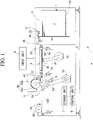
- Fig. 1 is a schematic diagram of the overall index tab forming system according to one embodiment of the present invention.
- the arrow X represents a conveyance direction of a sheet S.
- the index tab forming system includes a sheet stack unit 1, a sheet feeding unit 2, a conveyance unit 3, a rotary die cutter 5, an input unit 6, a storage unit 7, a rotational position detection unit 8, a control unit 9, and a discharge unit 10.
- the sheet stack unit 1 has a horizontal sheet loading shelf 1a arranged movably to be lifted and lowered and a perpendicular sheet alignment plate 1b arranged in front of the sheet loading shelf 1a and configured to align front ends of respective sheets S of a sheet stack P.
- the sheet stack P is placed on the sheet loading shelf 1a.
- the sheet feeding unit 2 has a suction belt conveyor 20, a suction duct 22, and a sheet feeding roller pair 24 on the upper front side of the sheet stack unit 1.
- the suction duct 22 is arranged on the upper side of the lower belt of the suction belt conveyor 20 and sucks and holds the uppermost sheet S of the sheet stack P.
- the suction belt conveyor 20 feeds the sucked and held sheet S out to the sheet feeding roller pair 24.
- the sheet feeding roller pair 24 rotates in the direction in which the sheet S is taken in from the suction belt conveyor 20, and the suction belt conveyor 20 stops the operation thereof when the sheet S is taken in the sheet feeding roller pair 24.
- the conveyance unit 3 has a suction belt conveyor 30, a timing belt 32, a motor 34, a suction duct 35, an intake pump 36, a conveyance roller pair 37, a timing belt 38, a motor 39, and a sheet detection sensor 40.
- the suction belt conveyor 30 is arranged downstream of the sheet feeding roller pair 24 and driven by the motor 34, to convey a sheet S fed from the sheet feeding unit 2 to the rotary die cutter 5 side.
- the suction duct 35 is arranged on the underside of the upper belt that forms a conveyance surface of the suction belt conveyor 30.
- the suction duct 35 has an intake port in the upper surface and is connected to the intake pump 36.
- the conveyance roller pair 37 is arranged in downstream of the suction belt conveyor 30 and driven by the motor 39 to convey the sheet S conveyed from the suction belt conveyor 30 to the rotary die cutter 5.
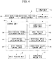
- the sheet detection sensor 40 is arranged downstream of the conveyance roller pair 37, detects a predetermined position of the conveyed sheet S, and transmits a detection signal to the control unit 9 (see Fig. 4 ).
- the sheet detection sensor 40 is an infrared sensor, an image reader that reads a mark printed on a predetermined portion of a sheet S, or the like and detects the front end of the sheet S, a mark on the sheet S, or the like.
- the sheet detection sensor 40 is an infrared sensor and detects the front end of a sheet S.
- the rotary die cutter 5 has a die cut roller 50, a receiving roller 52, a timing belt 54, and a motor 55.
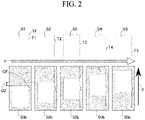
- the die cut roller 50 has a magnet roller 50a and a sheet-like blade die 50b used for index tab forming mounted on the magnet roller 50a.
- the blade die 50b is formed such that the circumferential length is sufficiently longer than the length of a sheet S so that index tabs T can be formed sequentially on sheets S1 to S5.
- the arrow Y represents the processing order of sheets S.
- An index tab T1 of the sheet S1 corresponds to "top index tab” of the present invention.
- the distance between a front end TF of the index tab T1 of the sheet S1 and a front end TF of an index tab T2 of the sheet S2 corresponds to "shift distance between respective index tabs" of the present invention.
- the index tabs T are formed to the sheets S1 to S5 sequentially at different positions, respectively.
- the number of index tabs T (five in the present embodiment) corresponds to "the total number of index tabs" of the present invention.
- the receiving roller 52 is arranged parallel to the die cut roller 50 with a predetermined spacing thereto.
- the motor 55 is an induction motor, which is only an example and is not limited thereto.
- the receiving roller 52 is connected to the motor 55 via the timing belt 54 and is driven by the motor 55.
- the die cut roller 50 is coupled to the receiving roller 52 via a gear (not illustrated) and thereby rotates in synchronization with the receiving roller 52.
- the die cut roller 50 and the receiving roller 52 continually rotate at a constant speed in the direction in which a sheet S is introduced from the conveyance roller pair 37.
- the rotary die cutter 5 is configured such that a sheet S is conveyed by the conveyance roller pair 37 through a gap between the die cut roller 50 and the receiving roller 52, and an index tab T is formed by the blade die 50b during the conveyance.
- the rotational position detection unit 8 is a rotary encoder, which is only an example and is not limited thereto.
- the rotational position detection unit 8 is configured to come into contact with the timing belt 54 from the outside and rotate in synchronization with driving of the timing belt 54. Accordingly, the rotational position detection unit 8 detects the rotational position of the receiving roller 52, detects the rotational position of the die cut roller 50 that rotates in synchronization with the receiving roller 52, and as a result, detects the rotational position of the front end CF (see Fig. 2 ) of an index tab portion of the blade die 50b.
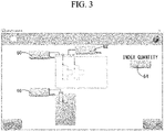
- the input unit 6 is a touch panel, which is only an example and is not limited thereto.
- the input unit 6 has a sheet tab position input unit 60 that receives input of a distance from the front end of the sheet S1 to the front end TF (see Fig.
- index tab the index tab T1 to be formed
- shift distance input unit 62 that receives input of a shift distance (d2) that is the distance from the front end TF of the index tab T1 to the front end TF of the next index tab T2
- tab quantity input unit 64 that receives input of the total number of index tabs T
- blade die tab position input unit 66 that receives input of a position of the front end CF of the index tab portion of the blade die 50b.
- the input values are stored in the storage unit 7, respectively.
- the control unit 9 has a sheet feeding timing determination unit 90, a sheet feeding count unit 92, a shift period calculation unit 93, a sheet feeding control unit 94, a rotational speed calculation unit 95, a conveyance roller control unit 96, and a conveyance count unit 97.
- the sheet feeding timing determination unit 90 determines a sheet feeding timing of the sheet S1 on which the index tab T1 is formed. How to find a sheet feeding timing will be described with reference to Fig. 5 .
- the correspondence relationship between each symbol in Fig. 5 and an element denoted by each symbol is as follows.
- t 1 L 1 + L 2 + d 1 / v 2 .
- the sheet feeding count unit 92 counts the number of times n1 that the sheet feeding unit 2 feeds a sheet.
- the shift period calculation unit 93 calculates a period to shift sheet feeding timings of the sheets S other than the sheet S1 based on the shift distance d2 input to the shift distance input unit 62 and the number of times n1 of sheet feeding counted by the sheet feeding count unit 92. That is, since the sheets S2 to S5 other than the sheet S1 are required to be fed with a predetermined period shifted from the timing when the sheet S1 is fed by the sheet feeding unit 2 based on the positions of the index tabs T2 to T5, the shift period calculation unit 93 calculates a period st to be shifted.
- t2 L 1 + L 2 + d 1 + d 2 / v 2 .
- the sheet feeding control unit 94 controls, based on a rotational position of the die cut roller 50, the sheet feeding unit 2 to feed the sheet S1 to which the index tab T1 is formed at the sheet feeding timing determined by the sheet feeding timing determination unit 90. Further, the sheet feeding control unit 94 controls the sheet feeding unit 2 so as to feed the sheets S2 to S5, to which other index tabs T2 to T5 are formed, at timings shifted forward from the sheet feeding timing by the shift period st calculated by the shift period calculation unit 93.
- the sheet feeding count unit 92 may reset the count of the number of times n1 of sheet feeding every time the sheet S5 to which the last index tab T5 is formed is fed by the sheet feeding unit 2. Accordingly, the operation in which the sheet feeding unit 2 feeds the sheets S1 to S5 is repeated.
- the conveyance count unit 97 counts the number of times n2 that the conveyance unit 3 conveys a sheet S to the rotary die cutter 5.
- the rotational speed calculation unit 95 calculates a rotational speed of the conveyance roller pair 37 that causes the front end CF of the index tab portion of the blade die 50b and the front end TF of the index tab T of the sheet S to match at the lowermost point of the die cut roller 50 based on the rotational position of the die cut roller 50, a detection signal generated when the sheet detection sensor 40 detects the front end of the sheet S, the number of times n2 that the conveyance unit 3 conveys the sheet S to the rotary die cutter 5, and the shift distance d2 between index tabs.
- the rotational speed calculation unit 95 calculates the rotational speed of the conveyance roller pair 37 that can obtain the conveyance speed v.
- the conveyance roller control unit 96 controls the rotation of the conveyance roller pair 37 based on the rotational speed calculated by the rotational speed calculation unit 95. Accordingly, the timing of the sheet S introduced into the rotary die cutter 5 is corrected, and the index tab T is formed at a suitable position of the sheet S.
- the conveyance count unit 97 may reset the count of the number of times n2 of conveyance every time the sheet S5 to which the last index tab T5 is formed is conveyed to the rotary die cutter 5 by the conveyance unit 3. Accordingly, the operation in which the conveyance unit 3 conveys the sheets S1 to S5 is repeated. That is, counts counted by the sheet feeding count unit 92 and the conveyance count unit 97 are reset at a predetermined timing, and thereby the operation in which the index tabs T1 to T5 are formed in the index tab forming system is repeated.
- the conveyance roller control unit 96 controls the rotational speed of the conveyance roller pair 37 so that the conveyance speed v of the sheet S matches the circumferential speed v1 of the blade die 50b before the sheet S5 leaves the blade die 50b after the front end TF of the index tab T of the sheet S matches the front end CF of the index tab portion of the blade die 50b at the point Q.
- the discharge unit 10 has a conveyor belt 100 extending from the exit of the die cut roller 50 and the receiving roller 52 to the discharge port of the index tab forming system and a conveyance roller 101 arranged near the downstream end of the conveyor belt 100.
- the discharge unit 10 uses the conveyor belt 100 and the conveyance roller 101 to convey the sheet S to which the index tab T has been formed and discharge the sheet S from the discharge port of the index tab forming system.
- the index tab forming system can sequentially form the index tabs T1 to T5 to the plurality of sheets S1 to S5 without replacing the blade die 50b.
- the index tab forming system can form the index tab T at a suitable position of the sheet S by correcting the timing of the sheet S introduced into the rotary die cutter 5 by the conveyance roller pair 37.
- the index tab forming system feeds the sheet S while shifting the sheet feeding timing in accordance with the position of the index tab T to be formed and thus can convey the sheet S to the rotary die cutter 5 without suspending the conveyance of the sheet S in front of the rotary die cutter 5 or slowing down the drive speed of the suction belt conveyor 30 to be lower than a normal drive speed.
Landscapes
- Engineering & Computer Science (AREA)
- Mechanical Engineering (AREA)
- Life Sciences & Earth Sciences (AREA)
- Forests & Forestry (AREA)
- Computer Vision & Pattern Recognition (AREA)
- Perforating, Stamping-Out Or Severing By Means Other Than Cutting (AREA)
- Control Of Cutting Processes (AREA)
- Making Paper Articles (AREA)
- Labeling Devices (AREA)
Applications Claiming Priority (1)
| Application Number | Priority Date | Filing Date | Title |
|---|---|---|---|
| PCT/JP2019/042033 WO2021079519A1 (ja) | 2019-10-25 | 2019-10-25 | インデックスタブ形成システム |
Publications (2)
| Publication Number | Publication Date |
|---|---|
| EP4049818A1 true EP4049818A1 (de) | 2022-08-31 |
| EP4049818A4 EP4049818A4 (de) | 2023-08-02 |
Family
ID=75620608
Family Applications (1)
| Application Number | Title | Priority Date | Filing Date |
|---|---|---|---|
| EP19950206.3A Withdrawn EP4049818A4 (de) | 2019-10-25 | 2019-10-25 | System zur bildung von indexlaschen |
Country Status (5)
| Country | Link |
|---|---|
| US (1) | US12344502B2 (de) |
| EP (1) | EP4049818A4 (de) |
| JP (1) | JP7218964B2 (de) |
| CN (1) | CN114585488B (de) |
| WO (1) | WO2021079519A1 (de) |
Families Citing this family (1)
| Publication number | Priority date | Publication date | Assignee | Title |
|---|---|---|---|---|
| US9201420B2 (en) | 2005-04-08 | 2015-12-01 | Rosemount, Inc. | Method and apparatus for performing a function in a process plant using monitoring data with criticality evaluation data |
Family Cites Families (8)
| Publication number | Priority date | Publication date | Assignee | Title |
|---|---|---|---|---|
| JP2943105B2 (ja) * | 1998-01-09 | 1999-08-30 | 株式会社ミヤコシ | インデックス作成装置 |
| JP4188516B2 (ja) * | 1999-10-08 | 2008-11-26 | 三菱重工食品包装機械株式会社 | トレイ容器打抜装置 |
| JP6011120B2 (ja) * | 2012-08-01 | 2016-10-19 | セイコーエプソン株式会社 | シートカートリッジ、ラベル作成装置およびラベル作成装置の制御方法 |
| JP5815493B2 (ja) * | 2012-10-15 | 2015-11-17 | 京セラドキュメントソリューションズ株式会社 | シート搬送装置、原稿搬送装置および画像形成装置 |
| JP5804582B2 (ja) | 2013-04-26 | 2015-11-04 | ホリゾン・インターナショナル株式会社 | 回転式打抜機 |
| JP5554861B1 (ja) * | 2013-05-07 | 2014-07-23 | ホリゾン・インターナショナル株式会社 | 回転式打抜機 |
| JP2015006702A (ja) * | 2013-06-24 | 2015-01-15 | 株式会社ユウコス | ロータリーダイカッターシステム |
| CN208246992U (zh) * | 2018-05-22 | 2018-12-18 | 珠海天达电子有限公司 | 一种全自动模切机 |
-
2019
- 2019-10-25 EP EP19950206.3A patent/EP4049818A4/de not_active Withdrawn
- 2019-10-25 WO PCT/JP2019/042033 patent/WO2021079519A1/ja not_active Ceased
- 2019-10-25 US US17/771,323 patent/US12344502B2/en active Active
- 2019-10-25 JP JP2021553881A patent/JP7218964B2/ja active Active
- 2019-10-25 CN CN201980101588.0A patent/CN114585488B/zh active Active
Also Published As
| Publication number | Publication date |
|---|---|
| US20220371840A1 (en) | 2022-11-24 |
| CN114585488B (zh) | 2024-02-06 |
| JPWO2021079519A1 (de) | 2021-04-29 |
| CN114585488A (zh) | 2022-06-03 |
| WO2021079519A1 (ja) | 2021-04-29 |
| JP7218964B2 (ja) | 2023-02-07 |
| US12344502B2 (en) | 2025-07-01 |
| EP4049818A4 (de) | 2023-08-02 |
Similar Documents
| Publication | Publication Date | Title |
|---|---|---|
| CN103213410B (zh) | 票据纸切纸控制装置和出票机 | |
| JP5578830B2 (ja) | シート処理装置、画像形成装置及び画像形成システムの制御方法 | |
| CA2768784C (en) | Device and method for placing plate-like elements in a processing machine | |
| EP2871146B1 (de) | Blattzufuhrvorrichtung | |
| EP2796253A2 (de) | Stanzmaschine | |
| JP2011090093A5 (ja) | シート処理装置、画像形成装置及び画像形成システムの制御方法 | |
| EP3326945A1 (de) | Folienschneidvorrichtung | |
| EP3453658B1 (de) | Zuführvorrichtung und blattverarbeitungsvorrichtung damit | |
| JPH092704A (ja) | 斜行検出機能を有する媒体搬送装置 | |
| EP4049818A1 (de) | System zur bildung von indexlaschen | |
| EP2402271A2 (de) | Blatthandhabungsvorrichtung und Blatthandhabungsverfahren | |
| EP4032838A1 (de) | Vorrichtung und verfahren zur förderungssteuerung | |
| EP3770090B1 (de) | Steuerungsvorrichtung und zuführvorrichtung | |
| JP5554861B1 (ja) | 回転式打抜機 | |
| JP2014201441A (ja) | シート裁断及び丁合装置 | |
| US10611183B2 (en) | Saddle-stitch book binding system | |
| JP6032814B2 (ja) | 丁合機 | |
| JPS631668A (ja) | 紙葉類集積装置 | |
| US20250243017A1 (en) | Stacking device and machining processing device including the same | |
| EP2409786B1 (de) | Vereinzelervorrichtung für mit Transparentfolie beschichtete Postsendungen | |
| US20250361108A1 (en) | Stacker and machining processing device | |
| JPH0711073Y2 (ja) | マークテープ自動挿入装置 | |
| JPH0742022B2 (ja) | 紙葉類集積装置 | |
| JP2025052715A (ja) | 積載装置 | |
| JP5512015B1 (ja) | ローラー式打抜き機 |
Legal Events
| Date | Code | Title | Description |
|---|---|---|---|
| STAA | Information on the status of an ep patent application or granted ep patent |
Free format text: STATUS: THE INTERNATIONAL PUBLICATION HAS BEEN MADE |
|
| PUAI | Public reference made under article 153(3) epc to a published international application that has entered the european phase |
Free format text: ORIGINAL CODE: 0009012 |
|
| STAA | Information on the status of an ep patent application or granted ep patent |
Free format text: STATUS: REQUEST FOR EXAMINATION WAS MADE |
|
| 17P | Request for examination filed |
Effective date: 20220421 |
|
| AK | Designated contracting states |
Kind code of ref document: A1 Designated state(s): AL AT BE BG CH CY CZ DE DK EE ES FI FR GB GR HR HU IE IS IT LI LT LU LV MC MK MT NL NO PL PT RO RS SE SI SK SM TR |
|
| DAV | Request for validation of the european patent (deleted) | ||
| DAX | Request for extension of the european patent (deleted) | ||
| A4 | Supplementary search report drawn up and despatched |
Effective date: 20230629 |
|
| RIC1 | Information provided on ipc code assigned before grant |
Ipc: B26D 7/06 20060101ALI20230623BHEP Ipc: B26D 5/32 20060101ALI20230623BHEP Ipc: B26D 5/28 20060101ALI20230623BHEP Ipc: B26D 5/00 20060101ALI20230623BHEP Ipc: B26D 3/10 20060101ALI20230623BHEP Ipc: B26F 1/38 20060101ALI20230623BHEP Ipc: B26D 5/20 20060101ALI20230623BHEP Ipc: B26D 1/40 20060101AFI20230623BHEP |
|
| STAA | Information on the status of an ep patent application or granted ep patent |
Free format text: STATUS: THE APPLICATION HAS BEEN WITHDRAWN |
|
| 18W | Application withdrawn |
Effective date: 20251016 |