EP4049599B1 - Behandlungsvorrichtung mit dämpfungsfunktion - Google Patents
Behandlungsvorrichtung mit dämpfungsfunktion Download PDFInfo
- Publication number
- EP4049599B1 EP4049599B1 EP22155755.6A EP22155755A EP4049599B1 EP 4049599 B1 EP4049599 B1 EP 4049599B1 EP 22155755 A EP22155755 A EP 22155755A EP 4049599 B1 EP4049599 B1 EP 4049599B1
- Authority
- EP
- European Patent Office
- Prior art keywords
- transmission rod
- probe
- treatment device
- jaw
- surgical treatment
- Prior art date
- Legal status (The legal status is an assumption and is not a legal conclusion. Google has not performed a legal analysis and makes no representation as to the accuracy of the status listed.)
- Active
Links
Images


Classifications
-
- A—HUMAN NECESSITIES
- A61—MEDICAL OR VETERINARY SCIENCE; HYGIENE
- A61B—DIAGNOSIS; SURGERY; IDENTIFICATION
- A61B17/00—Surgical instruments, devices or methods
- A61B17/32—Surgical cutting instruments
- A61B17/320068—Surgical cutting instruments using mechanical vibrations, e.g. ultrasonic
-
- A—HUMAN NECESSITIES
- A61—MEDICAL OR VETERINARY SCIENCE; HYGIENE
- A61B—DIAGNOSIS; SURGERY; IDENTIFICATION
- A61B17/00—Surgical instruments, devices or methods
- A61B17/32—Surgical cutting instruments
- A61B17/320068—Surgical cutting instruments using mechanical vibrations, e.g. ultrasonic
- A61B17/320092—Surgical cutting instruments using mechanical vibrations, e.g. ultrasonic with additional movable means for clamping or cutting tissue, e.g. with a pivoting jaw
-
- A—HUMAN NECESSITIES
- A61—MEDICAL OR VETERINARY SCIENCE; HYGIENE
- A61N—ELECTROTHERAPY; MAGNETOTHERAPY; RADIATION THERAPY; ULTRASOUND THERAPY
- A61N7/00—Ultrasound therapy
-
- A—HUMAN NECESSITIES
- A61—MEDICAL OR VETERINARY SCIENCE; HYGIENE
- A61B—DIAGNOSIS; SURGERY; IDENTIFICATION
- A61B17/00—Surgical instruments, devices or methods
- A61B17/32—Surgical cutting instruments
- A61B17/320068—Surgical cutting instruments using mechanical vibrations, e.g. ultrasonic
- A61B2017/320069—Surgical cutting instruments using mechanical vibrations, e.g. ultrasonic for ablating tissue
-
- A—HUMAN NECESSITIES
- A61—MEDICAL OR VETERINARY SCIENCE; HYGIENE
- A61B—DIAGNOSIS; SURGERY; IDENTIFICATION
- A61B17/00—Surgical instruments, devices or methods
- A61B17/32—Surgical cutting instruments
- A61B17/320068—Surgical cutting instruments using mechanical vibrations, e.g. ultrasonic
- A61B2017/320071—Surgical cutting instruments using mechanical vibrations, e.g. ultrasonic with articulating means for working tip
-
- A—HUMAN NECESSITIES
- A61—MEDICAL OR VETERINARY SCIENCE; HYGIENE
- A61B—DIAGNOSIS; SURGERY; IDENTIFICATION
- A61B17/00—Surgical instruments, devices or methods
- A61B17/32—Surgical cutting instruments
- A61B17/320068—Surgical cutting instruments using mechanical vibrations, e.g. ultrasonic
- A61B2017/320072—Working tips with special features, e.g. extending parts
-
- A—HUMAN NECESSITIES
- A61—MEDICAL OR VETERINARY SCIENCE; HYGIENE
- A61B—DIAGNOSIS; SURGERY; IDENTIFICATION
- A61B17/00—Surgical instruments, devices or methods
- A61B17/32—Surgical cutting instruments
- A61B17/320068—Surgical cutting instruments using mechanical vibrations, e.g. ultrasonic
- A61B2017/320082—Surgical cutting instruments using mechanical vibrations, e.g. ultrasonic for incising tissue
-
- A—HUMAN NECESSITIES
- A61—MEDICAL OR VETERINARY SCIENCE; HYGIENE
- A61B—DIAGNOSIS; SURGERY; IDENTIFICATION
- A61B17/00—Surgical instruments, devices or methods
- A61B17/32—Surgical cutting instruments
- A61B17/320068—Surgical cutting instruments using mechanical vibrations, e.g. ultrasonic
- A61B2017/320088—Surgical cutting instruments using mechanical vibrations, e.g. ultrasonic with acoustic insulation, e.g. elements for damping vibrations between horn and surrounding sheath
-
- A—HUMAN NECESSITIES
- A61—MEDICAL OR VETERINARY SCIENCE; HYGIENE
- A61B—DIAGNOSIS; SURGERY; IDENTIFICATION
- A61B17/00—Surgical instruments, devices or methods
- A61B17/32—Surgical cutting instruments
- A61B17/320068—Surgical cutting instruments using mechanical vibrations, e.g. ultrasonic
- A61B17/320092—Surgical cutting instruments using mechanical vibrations, e.g. ultrasonic with additional movable means for clamping or cutting tissue, e.g. with a pivoting jaw
- A61B2017/320094—Surgical cutting instruments using mechanical vibrations, e.g. ultrasonic with additional movable means for clamping or cutting tissue, e.g. with a pivoting jaw additional movable means performing clamping operation
Definitions
- the present disclosure relates to an ultrasonic treatment device used for dissecting and coagulating tissues.
- the ultrasonic treatment device is equipped with an ultrasonic transducer including piezoelectric elements converting electrical power into ultrasonic vibrations.
- the ultrasonic vibrations are transmitted along the transmission member to a probe that serves to clasp objects together with a jaw for the performance of treatment procedures on biological tissue of patients, such as blood vessel sealing.
- the transmission member may create undesired transverse vibration that causes problems such as deterioration of blood vessel sealing performance, heat generation, abnormal stress, and abnormal noise.
- FIG. 12 is a figure of an ultrasonic treatment device in the related art ( U.S. Pat. No. 8,696,666 ).
- the related art surgical operation system 1 consists of a handpiece 2, a main body apparatus 3 which is an output control apparatus, a foot switch 4 and a counter electrode plate 5.
- the handpiece 2 is a surgical treatment instrument capable of treatment using both ultrasonic and high-frequency current.
- the handpiece 2 is connected to the main body apparatus 3 via a cable 2 a which is attachable and detachable.
- the handpiece 2 has an insertion portion 2b and a handle portion 2c.
- the connector portion 3a connects the handpiece to the main body apparatus 3, which controls the output of the ultrasonic vibration and/or high-frequency current.
- the main body apparatus 3 has a plurality of displays 3b and a plurality of various operation buttons 3c for controlling the performance of handpiece 2.
- the foot switch 4 is connected to the main body apparatus 3 through a cable 4 a, and switches the mode from treatment using ultrasonic vibration, treatment using high-frequency current, or treatment using both.
- the counter electrode plate 5 is connected to the main body apparatus 3 through a cable 5 a.
- the counter electrode plate 5 is a return electrode for returning a current which passes through a subject at the time of monopolar output of a high-frequency current.
- FIG. 13 is a figure of a portion of an ultrasonic treatment device in the related art ( U.S. Pat. No. 5,989,275 ).
- the related art ultrasonic treatment device includes a transmission rod 86 used for transmitting ultrasonic vibrations to the ultrasonic probe.
- the transmission rod 86 is covered by a damping sheath 160, which is further covered by the elongated tubular member 174.
- Diametrically opposed openings 162b and 162c, as well as longitudinal slit 164 are formed on the damping sheath 160.
- Compliant members 190b and 190c are disposed around the periphery of the damping sheath 160, which are preferably disposed around the nodes to minimize damping of the desired longitudinal vibration.
- the damping sheath 160 is constructed of a polymeric material, preferably with a low coefficient of friction to minimize dissipation of energy from the axial motion or longitudinal vibration of the transmission rod 86.
- the damping sheath 160 is preferably in light contact with the transmission rod 86 to dampen or limit non-axial or transverse side-to-side vibration of the transmission rod 86.
- the damping sheath 160 can dampen transverse motion of the unwanted vibration which are located randomly along the length of the transmission rod 86 relative to the nodes and antinodes of the desired longitudinal vibration.
- the need for damping the transverse vibrations occurring at the ultrasonic probe decreases since the direct contact made between the ultrasonic probe and the human tissue or the other clasping feature results in damping of the transverse vibration.
- the contacting of the damping sheath 160 and the ultrasonic probe causes rise in the electric power and frictional heat during the treatment procedure using the longitudinal vibration. Therefore, a configuration is preferred in which damping occurs when the ultrasonic probe is not used for clasping but does not occur when the ultrasonic probe is used for clasping human tissues.
- US 2016/0278804 A1 refers to a treatment device that includes a treatment unit and a probe.
- the treatment device has an insertion section and an operation section.
- the insertion section includes a sheath and an action portion.
- a treatment section of the probe projects toward a distal end of the sheath on a distal end side.
- a support section which is made of a metallic material is arranged on an inner circumferential surface of or near the distal end of the sheath. The support section is arranged opposite to the action portion with respect to the probe.
- WO 2016/163450 A1 relates to a medical device which treats body tissue with ultrasonic vibration and includes a cover for preventing body tissue from being erroneously cauterized.
- the cover is arranged so that the vibration transmitting member is interposed between the cover and the jaw.
- the cover is connected to the jaw through a driving pin of a driving pipe so that the movement of the driving pipe actuates the opening/closing of the jaw and the rotation of the cover relative to the vibration transmitting member.
- Claim 1 defines the invention and dependent claims disclose embodiments. No surgical methods are claimed per se. Accordingly, there is a need for designing an ultrasonic treatment device with an efficient structure in view of the practical usage, which would substantially obviate one or more of the issues due to limitations and disadvantages of related art treatment devices.
- the invention is directed to the object to provide an improved surgical treatment device having an efficient structure and practical administration of the associated medical procedure. Further, the invention is directed to the object of controlling such a surgical treatment device.
- a surgical treatment device is provided, having the features defined in claim 1.
- Preferred embodiments are defined by the dependent claims. For example, there is a need to provide improved damping solutions that, for example, minimize the contact between a transmission rod and a damping structure, so as to minimize or prevent heat generation, abnormal noise, or other issues to arise.
- a surgical treatment device is equipped with an ultrasonic transducer transmitting ultrasonic vibration generated by the transducer to the treatment probe located at a distal end of the transmission rod.
- the treatment probe includes a treatment surface and a jaw moveable relative to the transmission rod from an open position to a closed position.
- the jaw may be movable relative to the treatment probe.
- the jaw may be movable relative to the treatment surface of the treatment probe.
- the treatment probe may be configured to clasp objects, such as biological tissue of a patient.
- the surgical treatment device further comprises a damping feature which is configured to contact the transmission rod configured to generate ultrasonic vibrations.
- the transducer may include piezoelectric elements converting electrical power into ultrasonic vibrations.
- the surgical treatment device further includes a transmission rod with a treatment probe, wherein a proximal end of the transmission rod is operatively connected to the transducer for transmitting ultrasonic vibration generated by the transducer to the treatment probe located at a distal end of the transmission rod.
- the treatment probe includes a treatment surface and a jaw moveable relative to the transmission rod from an open position to a closed position.
- the jaw may be movable relative to the treatment probe.
- the jaw may be movable relative to the treatment surface of the treatment probe.
- the treatment probe may be configured to clasp objects, such as biological tissue of a patient.
- the surgical treatment device further comprises a damping feature which is configured to contact the transmission rod when the jaw is in the open position, and to be spaced apart from the transmission rod when the jaw is in the closed position.
- the surgical treatment device may comprise a single damping feature. It is, however, also conceivable that the surgical treatment device comprises more than one damping features.
- the damping feature includes a probe holder and serves for damping transverse vibrations associated with the ultrasonic vibrations and may comprise a sheath on a portion of the transmission rod or treatment probe, an outer surface of the treatment probe configured to contact an inner surface of a surrounding structure, an outer surface of the transmission rod configured to contact an inner surface of a surrounding structure (such as the sheath of the surgical treatment device), or combinations of such features. Damping transverse vibrations minimizes or prevents excess vibrations and, among other things, decreases frictional heat caused by the damping features attenuating the ultrasonic vibrations.
- the damping feature includes the probe holder, which is a structure that at least partially circumscribes the outer circumference surface of the treatment probe and through which the treatment probe can slidably move. Movement of the jaw between an open position (when the jaw is not in contact with a surface of the treatment probe) and a closed position (when the jaw is in contact with a surface of the treatment probe) causes the outer circumference surface of the treatment probe to move from a first position in which the treatment probe is in contact with the damping feature (namely, contacting a surface of the probe holder) and a second position in which the treatment probe is spaced apart from the damping feature (namely, spaced apart from surfaces of the probe holder).
- the damping feature By being in contact with the damping feature when the jaw is in the open position (which is otherwise an unloaded condition of the treatment probe), the damping feature suppresses transverse vibration of the treatment probe.
- the jaw when the treatment probe is in a loaded condition by being in-use during a procedure, the jaw is in the closed position and the treatment probe is not in contact with the damping feature associated with the probe holder, for example, by the treatment probe being biased away from contacting a surface of the probe holder.
- the damping feature may also be associated with a drive member, which is a structure that slidably moves within the sheath of the treatment device to extend and retract the treatment probe and to actuate movement of the jaw. Movement of the drive member may cause the treatment probe to move and also for the jaw to move between an open position (when the jaw is not in contact with a surface of the treatment probe) and a closed position (when the jaw is in contact with a surface of the treatment probe).
- the treatment probe may be attached to the transmission rod at a transition region and, with rearward movement of treatment probe (i.e., in the retracting direction), a proximal end of the drive member may move toward and contact the surface of the transition region of the transmission rod.
- a damping feature may be located at the portion of the drive member that contacts the transition region.
- the damping feature of the drive member may be caused to contact the surface of the transition region of the transmission rod.
- movement of the drive member and the operation of the jaw can also be coordinated so that, when the treatment probe is in a loaded condition by being in-use during a procedure, the jaw is in the closed position and the damping feature of the drive member is not in contact with the surface of the transition region of the transmission rod, for example, by the drive member being slidably moved toward a distal end to separate the damping feature of the drive member from the surface of the transition region of the transmission rod.
- the damping feature may be provided integrally with the structure that opens and closes the jaw, and thereby switches the state of contact and separation between the damping feature and the transmission rod and/or treatment probe as the jaw is opened and closed. Still further, the damping features can be placed at either the antinode or the node of the ultrasonic vibrations.
- the damping feature may be made of insulate material.
- the damping feature may be made of resin.
- the damping feature may be made of rubber.
- the damping feature may have a square or rectangular shape.
- the damping feature may have a triangular shape.
- the probe holder may be configured to contact the transmission rod applying force in a radial direction.
- the probe holder may cover the transmission rod perpendicularly as to the treatment surface.
- the damping feature may be placed within half wavelength of the ultrasonic vibration from the distal end of the treatment probe in the axial proximal direction.
- the damping feature may be placed near a fulcrum of the jaw.
- the transmission rod may be displacable towards the direction the jaw closes in the closed position.
- the damping feature may be configured such that the contact between the damping feature and the transmission rod does not occur at a node of a transverse vibration of the ultrasonic vibration.
- the damping feature may be configured such that the contact between the damping feature and the transmission rod does not occur at an antinode of a longitudinal vibration of the ultrasonic vibration.
- the damping feature may be configured such that the contact between the damping feature and the transmission rod occurs at an antinode of a transverse vibration of the ultrasonic vibration.
- the treatment probe may be configured to treat biological tissue.
- the treatment probe may be configured as an electrode for treatment using high frequency currents.
- the treatment probe may include a curved shape.
- the damping feature may be configured to prevent short circuit between the transmission rod and other parts of the surgical treatment device.
- the surgical treatment device may further comprise a slider configured to move in a direction parallel with the transmission rod.
- the slider and the jaw may be configured so that, when the slider moves towards the proximal end of the transmission rod the jaw moves in the opening direction and, when the slider moves towards the distal end of the transmission rod the jaw moves in the closing direction.
- the damping feature may further include an elastic cushion and the slider may include the elastic cushion.
- the elastic cushion may be configured to move integrally with the slider.
- the transmission rod may includes a portion having a larger diameter compared to the other portions of the transmission rod.
- the diameter of the portion having a larger diameter may gradually increase.
- a surgical treatment device comprises a transducer generating ultrasonic vibrations and a transmission rod including a treatment probe.
- a proximal end of the transmission rod is operatively connected to the transducer for transmitting ultrasonic vibration generated by the transducer to the treatment probe located at a distal end of the transmission probe.
- the treatment probe includes a treatment surface and a jaw moveable relative to the transmission rod from an open position to a closed position.
- the jaw may be movable relative to the treatment probe.
- the jaw may be movable relative to the treatment surface of the treatment probe.
- the surgical treatment device comprises a slider configured to move in a direction parallel with the transmission rod.
- the slider and the jaw are configured so that, when the slider moves towards the proximal end of the transmission rod the jaw moves in the opening direction and, when the slider moves towards the distal end of the transmission rod the jaw moves in the closing direction.
- the slider includes a damping feature that is configured to contact the transmission rod when the jaw is in the open position and to be spaced apart from the transmission rod when the jaw is in the closed position.
- the slider may comprise a single damping feature. It is, however, also conceivable that the slider comprises more than one damping features.
- the surgical treatment device according to the second aspect may comprise features discussed above with reference to the surgical treatment device according to the second first aspect.
- the damping feature may be made of insulate material.
- the damping feature may be made of resin.
- the damping feature may be made of rubber.
- the damping feature may have a square or rectangular shape.
- the damping feature may have a triangular shape.
- the damping feature may be configured to contact the transmission rod applying force in the radial direction.
- the damping feature may be configured to move integrally with the slider.
- the damping feature may be configured such that the contact between the damping feature and the transmission rod does not occur at a node of a transverse vibration of the ultrasonic vibration.
- the damping feature may be configured such that the contact between the damping feature and the transmission rod does not occur at an antinode of a longitudinal vibration of the ultrasonic vibration.
- the damping feature may be configured such that the contact between the damping feature and the transmission rod occurs at an antinode of the transverse vibration of the ultrasonic vibration.
- the treatment probe may be configured to treat biological tissue.
- the treatment probe may be configured as an electrode for treatment using high frequency currents.
- the damping feature may be configured to prevent short circuit between the transmission rod and other parts of the treatment device.
- the treatment probe may include a curved shape.
- the transmission rod may includes a portion having a larger diameter compared to the other portions of the transmission rod.
- the diameter of the portion having a larger diameter may gradually increase.
- a method for controlling a surgical treatment device comprises operating a transducer so as to generate ultrasonic vibrations, and connecting a transmission rod including a treatment probe to the transducer for transmitting ultrasonic vibration generated by the transducer to the treatment probe.
- the method further comprises moving a jaw relative to a treatment surface of the transmission rod for opening and closing.
- the a jaw may be moved relative to a treatment surface of the treatment probe provided on the transmission rod.
- a damping feature contacts the transmission rod when the jaw is in the open position, and the damping feature is spaced apart from the transmission rod when the jaw is in the closed position.
- the method according to the third aspect may comprise anyone of the features described above with reference to the surgical treatment device of the first or the second aspect.
- a method for controlling a surgical treatment device comprises operating a transducer so as to generate ultrasonic vibrations, and connecting a transmission rod including a treatment probe to the transducer for transmitting ultrasonic vibration generated by the transducer to the treatment probe.
- the method further comprises moving a slider in a direction parallel with the transmission rod for opening and closing a jaw movable relative to a treatment surface of the transmission rod.
- a damping feature of the slider contacts the transmission rod when the jaw is in the open position and is spaced apart from the transmission rod when the jaw is in the closed position.
- the method according to the fourth aspect may comprise anyone of the features described above with reference to the surgical treatment device of the first or the second aspect.
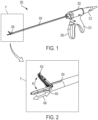
- FIG. 1 is an illustration of a surgical treatment device 300 including a body 302, a sheath 304, and a treatment end 306.
- the body 302 includes a moving arm 308, a grip 310, and a transducer 312.
- the moving arm 308 is used together with grip 310 to actuate and operate the functions of treatment end 306.
- the transducer 312 includes an ultrasonic transducer which is connected to a power source supplying power used for ultrasonic treatment and/or high-frequency treatment using surgical treatment device 300.
- the power source can be a wired or wireless power source.
- the sheath 304 protects the wires and members contained therein, such as those used for operating the functions of treatment end 306.
- FIG. 2 is the magnified view of the treatment end 306 of the surgical treatment device 300.
- the treatment end 306 consists of a jaw 402 and an ultrasonic probe 404.
- the jaw 402 moves (indicated by arrow M) relative to the ultrasonic probe 404 to open and close in the vertical direction through the manipulation of the movable handle 308 in order to clasp biological tissues and other objects for treatment.
- the ultrasonic probe 404 vibrates at an ultrasonic frequency transmitted through the transmission member within sheath 304.
- a longitudinal vibration, an ultrasonic vibration of the ultrasonic probe 404 made in the direction 406, creates frictional heat used for treatment purposes such as dissection of tissues, as well as frictional heat caused through contacting objects such as damping members.
- the ultrasonic probe 404 may have a curved shape and may also serves as an electrode for treatment using high frequency currents.
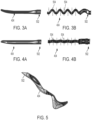
- FIG. 3A illustrates the ultrasonic probe 404 viewed from the vertical direction, the direction the jaw 402 opens and closes.
- FIG. 3A also illustrates the transmission member 502 extending in a distal direction from the ultrasonic probe 404, and which, within the arrangement of the treatment device, extends within the sheath 304 and connects to the transducer 312.
- the transmission member 502 is configured to transmit ultrasonic energy and/or high frequency energy from the transducer to the ultrasonic probe 404, which has a curved shape.
- the ultrasonic probe 404 and transmission member 502 are in a stationary state, i.e., a state where neither the ultrasonic vibration nor the high frequency current is applied to the ultrasonic probe 404 and transmission member 502.
- ultrasonic probe 404 in treatment procedures, longitudinal vibration would be the desirable ultrasonic vibration.
- transverse vibrations and torsional vibrations would be undesirable ultrasonic vibrations that may cause issues during the treatment procedures.
- the longitudinal vibration occurs in parallel to the center axis of the ultrasonic probe 404 and the undesired transverse vibration occurs in the direction perpendicular to the center axis of the ultrasonic probe and the longitudinal vibration. Because the ultrasonic probe 404 is curved in the horizontal direction with an aim to improve the visibility during the treatment procedure, the axial unbalance of the ultrasonic probe 404 in the horizontal direction may create substantial transverse vibrations when the ultrasonic vibration is applied to the ultrasonic probe 404. In the case shown in FIG.
- the ultrasonic vibration has caused a transverse vibration that includes antinodes (indicated in FIG. 3B by dashed lines 504 at the local maxima and minima) periodically along the length of the ultrasonic probe 404.
- the transverse vibration at the antinode 504 of the transverse vibration leads to problems such as heat generation, abnormal stress, and abnormal noise, and thus need to be attenuated.
- FIG. 4A illustrates the ultrasonic probe 404 viewed from the horizontal direction, the direction perpendicular to the vertical direction referred to in FIGS. 3A and 3B.
- FIG. 4A also illustrates the transmission member 502 extending from the ultrasonic probe 404, extending within the sheath 304, and connecting to the transducer 312.
- the ultrasonic probe 404 and transmission member 502 are in its stationary state, a state where neither the ultrasonic vibration nor the high frequency current is applied to the ultrasonic probe 404 and transmission member 502.
- FIG. 4B also illustrates the ultrasonic probe 404 viewed from the horizontal direction.
- FIG. 4A illustrates the ultrasonic probe 404 viewed from the horizontal direction, the direction perpendicular to the vertical direction referred to in FIGS. 3A and 3B.
- FIG. 4A also illustrates the transmission member 502 extending from the ultrasonic probe 404, extending within the sheath 304, and connecting to the transducer 312.
- FIG. 4B illustrates an exaggerated representation of the ultrasonic probe 404 and the transmission member 502 in an oscillating state, i.e., a state where the ultrasonic vibration is applied. Because the ultrasonic probe 404 is not curved in the vertical direction, axial unbalance in the vertical direction is minimal compared to the axial unbalance due to the curved ultrasonic probe 404 curving in the horizontal direction. Thus, the undesired transverse vibrations that may occur at the antinode 504 at the time of application of ultrasonic vibration is weak compared to the transverse vibrations in the horizontal direction as disclosed in FIG. 3B.
- FIG. 5 also illustrates an exaggerated representation of the ultrasonic probe 404 and the transmission member 502 in its perspective view. FIG. 5 illustrates the ultrasonic probe 404 and transmission member 502 in its oscillated state, showing the occurrence of undesired transverse vibration created due to the curve of the ultrasonic probe 404.
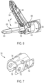
- FIG. 6 is a perspective view of the treatment end 306 of the surgical treatment device 300 in an open jaw state and showing aspects of a probe holder 700.
- the jaw 402 includes an upper clasping surface 604 facing the ultrasonic probe 404 and the ultrasonic probe 404 includes a lower clasping surface 606 facing the jaw 402.
- the upper clasping surface 604 and the lower clasping surface 606 move relative to each other, typically by having jaw 402 pivot about an axis located at fulcrum 610, in order to clasp biological tissues for treatment, such as dissection and/or coagulation.
- the relative movement M is actuated through the operation of the moving handle 308 and a motion mechanism, such as slider 608 embedded within the sheath 304.
- the jaw 402 is rotatably joined to the probe holder 700 and to a sheath 304, rotatable together with sheath 304.
- the probe holder 700 may be made from electrically insulated materials such as resin or rubber and the inner surfaces of the probe holder 700 at least partially circumscribe the outer circumference surface of the ultrasonic probe 404.
- the probe holder 700 slidably holds the ultrasonic probe 404 and, as described herein, with coordinated movement of the jaw 402 in the open direction, a region 706 (also called herein an upper holding portion) of the probe holder 700 contacts a surface of the ultrasonic probe 404, either with line contact or area contact, to attenuate ultrasonic vibration including transverse vibration that causes abnormal noise and other undesirable effects, particularly when the ultrasonic probe 404 is in an unloaded state, i.e., not in contact with biological tissue and/or not in contact with the jaw 402, particularly not in contact with the upper clasping surface 604 of the jaw 402.
- a base end 618 of the sheath 304 is connect to or otherwise interfaces with the sheath 304.
- FIG. 7 illustrates the probe holder 700 unaccompanied by other portions of the treatment end 306 of the surgical treatment device 300.
- the hole 702 in the probe holder 700 receives the fulcrum 610 or other structure in the base section of the jaw 402.
- the protrusion 704 provides a structure by which to connect the probe holder 700 to the sheath 304.
- protrusion 704 can be snap-fit into a corresponding recess or hole on the inner surface of the sheath 304, particularly located in intermediate region 616 of the sheath 304
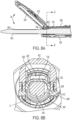
- FIG. 8A is a cross-sectional side view of the treatment end 306 of the surgical treatment device 300 in an open jaw state.
- the ultrasonic probe 404 extends through the probe holder 700 and sheath 304.
- the jaw 402 is opened using the slider 608, which acts on fulcrum 802 to pivotably move jaw 402 about fulcrum 610 (not shown).
- the region 706, e.g., the upper holding portion, of the probe holder 700 is in direct contact with the surface of ultrasonic probe 404, perpendicularly as to the treatment surface, and the direct contact serving to attenuate ultrasonic vibration including transverse vibrations when the ultrasonic probe 404 is in an oscillated state.
- the electrical insulation of the probe holder 700 prevents electrical currents to short circuit between the ultrasonic probe 404 to the other parts of the treatment end 306, such as fulcrum 802, jaw 402, slider 608, or sheath 304 during the high-frequency current treatment procedure.
- FIG. 8B is a cross-sectional axial view of the treatment end 306 of the surgical treatment device 300 in an open jaw state, viewed at the location A-A' indicated in FIG. 8A .
- the ultrasonic probe 404 extends through the probe holder 700 and sheath 304, which are joined together by the detents 804 and 806 on the jaw 402 at fulcrum 610.
- First detent 804 and second detent 806 can be integrally formed with the jaw 402 as shown in FIG. 8B , or can be separate structures affixed to the jaw 402.
- FIG. 8B also shows the slider 608 and fulcrum 802 that are used to open and close upper jaw 402.
- the ultrasonic probe 404 is biased toward and contacts the region 706, e.g., the upper holding portion, of the probe holder 700, serving to attenuate ultrasonic vibration including transverse vibrations when the ultrasonic probe 404 is in an oscillated state.
- the ultrasonic probe 404 is spaced apart from the probe holder 700 and sheath 304 at a circumferential location of the ultrasonic probe 404 that is 180 degrees from the location where the ultrasonic probe 404 is contacts the region 706, e.g., there is a space between the outer circumference surface of the ultrasonic probe 404 and the probe holder 700 and sheath 304 in region indicated by S in FIG. 8B .
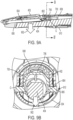
- FIG. 9A is a cross-sectional side view of the treatment end 306 of the surgical treatment device 300 in a close jaw state.
- the jaw 402 is closed using the slider 608, which acts on fulcrum 802 to pivotably move jaw 402 about fulcrum 610 (not shown).
- the upper clasping surface 604 contacts the lower clasping surface 606 of the ultrasonic probe 404 and applies a force in the downward direction 902. Due to the downward force 902 applied to the ultrasonic probe 404 by the jaw 402, the entirety of the ultrasonic probe 404 is displaced and pushed in the downward direction towards the space indicated by S in FIG.
- the surface of the ultrasonic probe 404 no longer contacts the region 706, e.g. the upper holding portion 706, of the probe holder 700. Since the region 706 is not in direct contact with ultrasonic probe 404 (and in contrast to the arrangement of these features in the open jaw state illustrated in FIGS. 8A-B ), the attenuation of the ultrasonic vibration using the probe holder 700 does not take place. However, through direct contact of the upper clasping surface 604 and the lower clasping surface 606 or direct contact of the lower clasping surface 606 with the biological tissue(s) to be treated, attenuation of the ultrasonic probe 404 would still occur.
- FIG. 9B is a cross-sectional axial view of the treatment end 306 of the surgical treatment device 300 in a closed jaw state, viewed at the location B-B' indicated in FIG. 9A .
- the jaw 402 is closed using the slider 608 acting on fulcrum 802 (not shown) to pivotably move jaw 402 about fulcrum 610.
- the gap G resulting from the downward force 902 discussed above is illustrated between the ultrasonic probe 404 and probe holder 700, in particular between the surface of the ultrasonic probe 404 and the region 702 (i.e. upper holding portion) of the probe holder 700.
- the attenuation of the ultrasonic vibration using the probe holder 700 does not take place. However, through direct contact of the upper clasping surface 604 and the lower clasping surface 606 or direct contact of the lower clasping surface 606 with the biological tissue(s) to be treated, attenuation of the ultrasonic probe 404 still occurs.
- FIG. 10A schematically illustrates the internal arrangement of the slider 608 and ultrasonic probe 404 of the surgical treatment device 300 in an open jaw state.
- the slider 608 is moved towards the proximal direction (i.e., in the direction indicated by arrow 1002) relative to the ultrasonic probe 404.
- the slider 608 includes a damping feature 1004, such as an elastic cushion made from insulation materials such as rubber and resin that moves together with the slider 608.
- the electrical insulation of the damping feature 1004 prevents electrical currents to short circuit between the ultrasonic probe 404 to the other parts of the treatment end 306 during the high-frequency current treatment procedure.
- FIG. 10B schematically illustrates the internal arrangement of the slider 608 and ultrasonic probe 404 of the surgical treatment device 300 in a closed jaw state.
- the slider 608 is moved towards the distal direction (i.e., in the direction indicated by arrow 1006) relative to the ultrasonic probe 404. Since the damping feature 1004 moves away from the thickened portion of the ultrasonic probe 404 or the transmission member 502 accompanying slider 608, the damping feature 1004 is spaced apart from and no longer directly contacts the ultrasonic probe 404 or the transmission member 502 and will no longer attenuate the transverse vibrations causing noise when the ultrasonic probe is at an oscillated state. However, as shown in FIGS.
- the attenuation of the ultrasonic probe 404 would, in this closed jaw state, be achieved through direct contact of the upper clasping surface 604 and the lower clasping surface 606 or direct contact of the lower clasping surface 606 with the biological tissue(s) to be treated.
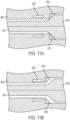
- FIG. 11A schematically illustrates the internal arrangement of the slider 608 and ultrasonic probe 404 of the surgical treatment device 300 in an open jaw state.
- the slider 608 is moved towards the proximal direction (i.e., in the direction indicated by arrow 1002) relative to the ultrasonic probe 404.
- the slider 608 includes a damping feature 1004, such as an elastic cushion, that moves together with the slider 608.
- the damping feature 1004 may have a triangular shape and can be affixed to the slider 608 or can be integrally formed with the slider 608. This configuration allows the damping feature to contact the transmission rod and apply force in the radial direction, which may effectively attenuate transverse vibrations.
- FIG. 11B schematically illustrates the internal arrangement of the slider 608 and ultrasonic probe 404 of the surgical treatment device 300 in a closed jaw state.
- the slider 608 is moved towards the distal direction (i.e., in the direction indicated by arrow 1006) relative to the ultrasonic probe 404. Since the damping feature 1004 moves away from the ultrasonic probe 404 or the included portion of the transmission member 502 accompanying slider 608, the damping feature 1004 is spaced apart from and no longer directly contacts the ultrasonic probe 404 or the transmission member 502 and will no longer attenuate the transverse vibrations causing noise when the ultrasonic probe is at an oscillated state. However, as shown in FIGS.
- the attenuation of the ultrasonic probe 404 would, in this closed jaw state, be achieved through direct contact of the upper clasping surface 604 and the lower clasping surface 606 or direct contact of the lower clasping surface 606 with the biological tissue(s) to be treated.
Landscapes
- Health & Medical Sciences (AREA)
- Life Sciences & Earth Sciences (AREA)
- Engineering & Computer Science (AREA)
- Surgery (AREA)
- Public Health (AREA)
- Biomedical Technology (AREA)
- Animal Behavior & Ethology (AREA)
- General Health & Medical Sciences (AREA)
- Nuclear Medicine, Radiotherapy & Molecular Imaging (AREA)
- Veterinary Medicine (AREA)
- Mechanical Engineering (AREA)
- Dentistry (AREA)
- Heart & Thoracic Surgery (AREA)
- Medical Informatics (AREA)
- Molecular Biology (AREA)
- Radiology & Medical Imaging (AREA)
- Surgical Instruments (AREA)
- Heat Treatment Of Articles (AREA)
- Heat Treatments In General, Especially Conveying And Cooling (AREA)
Claims (13)
- Chirurgische Behandlungsvorrichtung (300), die umfasst:einen Wandler (312), der konfiguriert ist, um Ultraschallschwingungen zu erzeugen; undeinen Übertragungsstab (502), der eine Behandlungssonde (404) umfasst, wobei ein proximales Ende des Übertragungsstabs (502) operativ mit dem Wandler (312) verbunden ist, um von dem Wandler (312) erzeugte Ultraschallschwingungen an die Behandlungssonde (404) zu übertragen, die sich an einem distalen Ende des Übertragungsstabs (502) befindet, und wobei die Behandlungssonde (404) eine Behandlungsfläche (606) und eine Klemmbacke (402) umfasst, die relativ zu dem Übertragungsstab (502) von einer offenen Position in eine geschlossene Position bewegbar ist,wobei die chirurgische Behandlungsvorrichtung (300) ein Dämpfungselement (700, 1004) umfasst, das so konfiguriert ist, dass es den Übertragungsstab (502) berührt, wenn sich die Klemmbacke (402) in der offenen Position befindet, und von dem Übertragungsstab (502) beabstandet ist, wenn sich die Klemmbacke (402) in der geschlossenen Position befindet,dadurch gekennzeichnet, dassdas Dämpfungselement (700, 1004) einen Sondenhalter (700) umfasst, der eine Außenumfangsfläche der Behandlungssonde (404) zumindest teilweise umgibt und durch den die Behandlungssonde (404) verschiebbar bewegbar ist,der Sondenhalter (700) einen Bereich (706) umfasst, der die Ultraschallschwingungen durch Kontakt mit dem Übertragungsstab (502) dämpft, undder Sondenhalter (700) so konfiguriert ist, dass er den Übertragungsstab (502) berührt, wenn sich die Klemmbacke (402) in der offenen Position befindet, und von dem Übertragungsstab (502) beabstandet ist, wenn sich die Klemmbacke (402) in der geschlossenen Position befindet.
- Chirurgische Behandlungsvorrichtung (300) nach Anspruch 1,- wobei das Dämpfungselement (700, 1004) aus Isoliermaterial besteht; und/oder- wobei das Dämpfungselement (700, 1004) aus Harz besteht; und/oder- wobei das Dämpfungselement (700, 1004) aus Gummi besteht; und/oder- wobei das Dämpfungselement (700, 1004) eine quadratische, rechteckige und/oder dreieckige Form aufweist.
- Chirurgische Behandlungsvorrichtung (300) nach Anspruch 1, wobei das Dämpfungselement (700, 1004) so konfiguriert ist, dass es den Übertragungsstab (502) berührt und eine Kraft in einer radialen Richtung aufbringt.
- Chirurgische Behandlungsvorrichtung (300) nach Anspruch 1, wobei der Sondenhalter (700) den Übertragungsstab (502) senkrecht zu der Behandlungsoberfläche (606) abdeckt.
- Chirurgische Behandlungsvorrichtung (300) nach Anspruch 1,- wobei das Dämpfungselement (700, 1004) innerhalb einer halben Wellenlänge der Ultraschallschwingungen von dem distalen Ende der Behandlungssonde (502) in der axialen proximalen Richtung angeordnet ist; und/oder- wobei das Dämpfungselement (700, 1004) in der Nähe eines Drehpunkts (610) der Klemmbacke (402) angeordnet ist.
- Chirurgische Behandlungsvorrichtung (300) nach Anspruch 1, wobei der Übertragungsstab (502) in die Richtung verschiebbar ist, in der sich die Klemmbacke (402) in die geschlossene Position schließt.
- Chirurgische Behandlungsvorrichtung (300) nach Anspruch 1,- wobei die Behandlungssonde (502) zur Behandlung von biologischem Gewebe konfiguriert ist; und/oder- wobei die Behandlungssonde (502) als Elektrode zur Behandlung unter Verwendung von Hochfrequenzströmen konfiguriert ist; und/oder- wobei die Behandlungssonde (502) eine gekrümmte Form umfasst.
- Chirurgische Behandlungsvorrichtung (300) nach Anspruch 1, wobei das Dämpfungselement (700, 1004) so konfiguriert ist, dass es einen Kurzschluss zwischen dem Übertragungsstab (502) und anderen Teilen der chirurgischen Behandlungsvorrichtung (300) verhindert.
- Chirurgische Behandlungsvorrichtung (300) nach Anspruch 1,
die ferner einen Gleiter (608) umfasst, der so konfiguriert ist, dass er sich in einer Richtung parallel zu dem Übertragungsstab (502) bewegt. - Chirurgische Behandlungsvorrichtung (300) nach Anspruch 9, wobei der Gleiter (608) und die Klemmbacke (402) so konfiguriert sind, dass sich die Klemmbacke proximalen Endes des Übertragungsstabs(502) bewegt, und sich die Klemmbacke (402) in der Schließrichtung bewegt, wenn sich der Gleiter (608) in Richtung des distalen Endes des Übertragungsstabs (502) bewegt.
- Chirurgische Behandlungsvorrichtung (300) nach Anspruch 9, wobei das Dämpfungselement (700, 1004) ferner ein elastisches Kissen (1004) umfasst und der Gleiter (608) das elastische Kissen (1004) umfasst.
- Chirurgische Behandlungsvorrichtung (300) nach Anspruch 11, wobei das elastische Kissen (1004) so konfiguriert ist, dass es sich integral mit dem Gleiter (608) bewegt.
- Chirurgische Behandlungsvorrichtung (300) nach Anspruch 1, wobei der Übertragungsstab (502) einen Abschnitt umfasst, der einen größeren Durchmesser im Vergleich zu den anderen Abschnitten des Übertragungsstabs (502) aufweist, wobei der Durchmesser des Abschnitts mit einem größeren Durchmesser insbesondere graduell zunimmt.
Priority Applications (1)
| Application Number | Priority Date | Filing Date | Title |
|---|---|---|---|
| EP24206050.7A EP4467088B1 (de) | 2021-02-24 | 2022-02-09 | Behandlungsvorrichtung mit dämpfungsfunktion |
Applications Claiming Priority (2)
| Application Number | Priority Date | Filing Date | Title |
|---|---|---|---|
| US202163152899P | 2021-02-24 | 2021-02-24 | |
| US17/558,665 US12239338B2 (en) | 2021-02-24 | 2021-12-22 | Treatment device with damping feature |
Related Child Applications (2)
| Application Number | Title | Priority Date | Filing Date |
|---|---|---|---|
| EP24206050.7A Division EP4467088B1 (de) | 2021-02-24 | 2022-02-09 | Behandlungsvorrichtung mit dämpfungsfunktion |
| EP24206050.7A Division-Into EP4467088B1 (de) | 2021-02-24 | 2022-02-09 | Behandlungsvorrichtung mit dämpfungsfunktion |
Publications (2)
| Publication Number | Publication Date |
|---|---|
| EP4049599A1 EP4049599A1 (de) | 2022-08-31 |
| EP4049599B1 true EP4049599B1 (de) | 2024-12-11 |
Family
ID=80446323
Family Applications (2)
| Application Number | Title | Priority Date | Filing Date |
|---|---|---|---|
| EP24206050.7A Active EP4467088B1 (de) | 2021-02-24 | 2022-02-09 | Behandlungsvorrichtung mit dämpfungsfunktion |
| EP22155755.6A Active EP4049599B1 (de) | 2021-02-24 | 2022-02-09 | Behandlungsvorrichtung mit dämpfungsfunktion |
Family Applications Before (1)
| Application Number | Title | Priority Date | Filing Date |
|---|---|---|---|
| EP24206050.7A Active EP4467088B1 (de) | 2021-02-24 | 2022-02-09 | Behandlungsvorrichtung mit dämpfungsfunktion |
Country Status (4)
| Country | Link |
|---|---|
| US (2) | US12239338B2 (de) |
| EP (2) | EP4467088B1 (de) |
| JP (1) | JP7331170B2 (de) |
| CN (1) | CN114948098B (de) |
Families Citing this family (1)
| Publication number | Priority date | Publication date | Assignee | Title |
|---|---|---|---|---|
| JP1702878S (de) * | 2021-04-09 | 2021-12-20 |
Citations (1)
| Publication number | Priority date | Publication date | Assignee | Title |
|---|---|---|---|---|
| WO2016163450A1 (ja) * | 2015-04-10 | 2016-10-13 | オリンパス株式会社 | 医療機器 |
Family Cites Families (16)
| Publication number | Priority date | Publication date | Assignee | Title |
|---|---|---|---|---|
| US5397293A (en) * | 1992-11-25 | 1995-03-14 | Misonix, Inc. | Ultrasonic device with sheath and transverse motion damping |
| US5989275A (en) | 1997-02-28 | 1999-11-23 | Ethicon Endo-Surgery, Inc. | Damping ultrasonic transmission components |
| US20040024393A1 (en) * | 2002-08-02 | 2004-02-05 | Henry Nita | Therapeutic ultrasound system |
| JP2001087274A (ja) * | 1999-09-24 | 2001-04-03 | Olympus Optical Co Ltd | 超音波処置具 |
| DE10141385B4 (de) * | 2000-08-25 | 2015-05-13 | Ethicon Endo-Surgery, Inc. | Chirurgisches Ultraschall-Instrurnent mit einem Dämpfungselement sowie Ultraschall-Übertragungsstab |
| JP4472395B2 (ja) * | 2003-08-07 | 2010-06-02 | オリンパス株式会社 | 超音波手術システム |
| JP4343778B2 (ja) * | 2004-06-16 | 2009-10-14 | オリンパス株式会社 | 超音波手術装置 |
| JP4856290B2 (ja) | 2010-03-31 | 2012-01-18 | オリンパスメディカルシステムズ株式会社 | 医療装置 |
| US20120109184A1 (en) * | 2010-11-01 | 2012-05-03 | Ethicon Endo-Surgery, Inc. | Vibratory motor use |
| WO2012081337A1 (ja) * | 2010-12-17 | 2012-06-21 | オリンパスメディカルシステムズ株式会社 | 生体組織を処置するプローブ及び生体組織の処置方法 |
| EP2898845B1 (de) * | 2012-09-24 | 2017-05-10 | Olympus Corporation | Betriebene ultraschalleinheit und ultraschallvorrichtung zur behandlung |
| EP3081183A4 (de) | 2013-12-13 | 2017-08-02 | Olympus Corporation | Behandlungsinstrument und behandlungssystem |
| WO2015088014A1 (ja) * | 2013-12-13 | 2015-06-18 | オリンパス株式会社 | 処置具、処置具ユニット及び処置システム |
| WO2016181970A1 (ja) | 2015-05-12 | 2016-11-17 | オリンパス株式会社 | 超音波処置具 |
| US10206691B2 (en) * | 2015-10-29 | 2019-02-19 | Medtronic Xomed, Inc. | Method and apparatus to select vibration |
| US10028765B2 (en) | 2015-10-30 | 2018-07-24 | Ethicon Llc | Ultrasonic surgical instrument clamp arm with proximal nodal pad |
-
2021
- 2021-12-22 US US17/558,665 patent/US12239338B2/en active Active
-
2022
- 2022-02-03 JP JP2022015785A patent/JP7331170B2/ja active Active
- 2022-02-09 EP EP24206050.7A patent/EP4467088B1/de active Active
- 2022-02-09 EP EP22155755.6A patent/EP4049599B1/de active Active
- 2022-02-11 CN CN202210128697.5A patent/CN114948098B/zh active Active
-
2025
- 2025-01-29 US US19/040,095 patent/US20250169845A1/en active Pending
Patent Citations (1)
| Publication number | Priority date | Publication date | Assignee | Title |
|---|---|---|---|---|
| WO2016163450A1 (ja) * | 2015-04-10 | 2016-10-13 | オリンパス株式会社 | 医療機器 |
Also Published As
| Publication number | Publication date |
|---|---|
| CN114948098B (zh) | 2025-08-08 |
| CN114948098A (zh) | 2022-08-30 |
| US20220265306A1 (en) | 2022-08-25 |
| EP4467088A2 (de) | 2024-11-27 |
| US20250169845A1 (en) | 2025-05-29 |
| US12239338B2 (en) | 2025-03-04 |
| EP4467088B1 (de) | 2026-08-05 |
| EP4049599A1 (de) | 2022-08-31 |
| JP2022129374A (ja) | 2022-09-05 |
| EP4467088A3 (de) | 2025-02-19 |
| JP7331170B2 (ja) | 2023-08-22 |
Similar Documents
| Publication | Publication Date | Title |
|---|---|---|
| CN110650697B (zh) | 具有包括共享返回路径的电路的组合超声和电外科器械 | |
| US6090120A (en) | Articulating ultrasonic surgical instrument | |
| EP3073939B1 (de) | Chirurgisches ultraschallinstrument mit gestufter klemme | |
| US20040186463A1 (en) | Ultrasonic treatment apparatus | |
| WO2016163450A1 (ja) | 医療機器 | |
| JPWO2011099571A1 (ja) | 超音波処置具 | |
| JP2001008943A (ja) | 超音波処置具 | |
| US10813661B2 (en) | Ultrasonic treatment devices and systems | |
| BR112017001211B1 (pt) | Instrumento ultrassônico e método para montagem de um instrumento ultrassônico | |
| JP3354032B2 (ja) | 外科用鉗子及び超音波凝固切開装置 | |
| JP6211228B2 (ja) | 医療機器 | |
| CN105142550A (zh) | 具有夹持结构的超声外科剪 | |
| US20250169845A1 (en) | Treatment device with damping feature | |
| JP6147449B2 (ja) | 医療機器及び超音波手術装置 | |
| JP2022532504A (ja) | ブレード接地機構及び代替ピン設計 | |
| CN100522086C (zh) | 超声波处置装置 | |
| US20220265342A1 (en) | Treatment device with damping feature | |
| US20220265308A1 (en) | Treatment device with damping feature | |
| JP4436556B2 (ja) | 外科手術用超音波処置具 | |
| JP5188661B2 (ja) | 超音波外科器具用の減衰装置 | |
| WO2016075745A1 (ja) | 医療用処置装置 |
Legal Events
| Date | Code | Title | Description |
|---|---|---|---|
| PUAI | Public reference made under article 153(3) epc to a published international application that has entered the european phase |
Free format text: ORIGINAL CODE: 0009012 |
|
| STAA | Information on the status of an ep patent application or granted ep patent |
Free format text: STATUS: REQUEST FOR EXAMINATION WAS MADE |
|
| 17P | Request for examination filed |
Effective date: 20220209 |
|
| AK | Designated contracting states |
Kind code of ref document: A1 Designated state(s): AL AT BE BG CH CY CZ DE DK EE ES FI FR GB GR HR HU IE IS IT LI LT LU LV MC MK MT NL NO PL PT RO RS SE SI SK SM TR |
|
| P01 | Opt-out of the competence of the unified patent court (upc) registered |
Effective date: 20230528 |
|
| STAA | Information on the status of an ep patent application or granted ep patent |
Free format text: STATUS: EXAMINATION IS IN PROGRESS |
|
| 17Q | First examination report despatched |
Effective date: 20230721 |
|
| GRAP | Despatch of communication of intention to grant a patent |
Free format text: ORIGINAL CODE: EPIDOSNIGR1 |
|
| STAA | Information on the status of an ep patent application or granted ep patent |
Free format text: STATUS: GRANT OF PATENT IS INTENDED |
|
| INTG | Intention to grant announced |
Effective date: 20240612 |
|
| GRAJ | Information related to disapproval of communication of intention to grant by the applicant or resumption of examination proceedings by the epo deleted |
Free format text: ORIGINAL CODE: EPIDOSDIGR1 |
|
| STAA | Information on the status of an ep patent application or granted ep patent |
Free format text: STATUS: EXAMINATION IS IN PROGRESS |
|
| GRAS | Grant fee paid |
Free format text: ORIGINAL CODE: EPIDOSNIGR3 |
|
| STAA | Information on the status of an ep patent application or granted ep patent |
Free format text: STATUS: GRANT OF PATENT IS INTENDED |
|
| GRAP | Despatch of communication of intention to grant a patent |
Free format text: ORIGINAL CODE: EPIDOSNIGR1 |
|
| GRAA | (expected) grant |
Free format text: ORIGINAL CODE: 0009210 |
|
| STAA | Information on the status of an ep patent application or granted ep patent |
Free format text: STATUS: THE PATENT HAS BEEN GRANTED |
|
| INTC | Intention to grant announced (deleted) | ||
| INTG | Intention to grant announced |
Effective date: 20241030 |
|
| AK | Designated contracting states |
Kind code of ref document: B1 Designated state(s): AL AT BE BG CH CY CZ DE DK EE ES FI FR GB GR HR HU IE IS IT LI LT LU LV MC MK MT NL NO PL PT RO RS SE SI SK SM TR |
|
| REG | Reference to a national code |
Ref country code: GB Ref legal event code: FG4D |
|
| REG | Reference to a national code |
Ref country code: CH Ref legal event code: EP |
|
| REG | Reference to a national code |
Ref country code: IE Ref legal event code: FG4D |
|
| REG | Reference to a national code |
Ref country code: DE Ref legal event code: R096 Ref document number: 602022008507 Country of ref document: DE |
|
| REG | Reference to a national code |
Ref country code: LT Ref legal event code: MG9D |
|
| PG25 | Lapsed in a contracting state [announced via postgrant information from national office to epo] |
Ref country code: HR Free format text: LAPSE BECAUSE OF FAILURE TO SUBMIT A TRANSLATION OF THE DESCRIPTION OR TO PAY THE FEE WITHIN THE PRESCRIBED TIME-LIMIT Effective date: 20241211 |
|
| PG25 | Lapsed in a contracting state [announced via postgrant information from national office to epo] |
Ref country code: FI Free format text: LAPSE BECAUSE OF FAILURE TO SUBMIT A TRANSLATION OF THE DESCRIPTION OR TO PAY THE FEE WITHIN THE PRESCRIBED TIME-LIMIT Effective date: 20241211 |
|
| PG25 | Lapsed in a contracting state [announced via postgrant information from national office to epo] |
Ref country code: BG Free format text: LAPSE BECAUSE OF FAILURE TO SUBMIT A TRANSLATION OF THE DESCRIPTION OR TO PAY THE FEE WITHIN THE PRESCRIBED TIME-LIMIT Effective date: 20241211 |
|
| REG | Reference to a national code |
Ref country code: NL Ref legal event code: MP Effective date: 20241211 |
|
| PG25 | Lapsed in a contracting state [announced via postgrant information from national office to epo] |
Ref country code: ES Free format text: LAPSE BECAUSE OF FAILURE TO SUBMIT A TRANSLATION OF THE DESCRIPTION OR TO PAY THE FEE WITHIN THE PRESCRIBED TIME-LIMIT Effective date: 20241211 |
|
| PG25 | Lapsed in a contracting state [announced via postgrant information from national office to epo] |
Ref country code: NO Free format text: LAPSE BECAUSE OF FAILURE TO SUBMIT A TRANSLATION OF THE DESCRIPTION OR TO PAY THE FEE WITHIN THE PRESCRIBED TIME-LIMIT Effective date: 20250311 |
|
| PG25 | Lapsed in a contracting state [announced via postgrant information from national office to epo] |
Ref country code: LV Free format text: LAPSE BECAUSE OF FAILURE TO SUBMIT A TRANSLATION OF THE DESCRIPTION OR TO PAY THE FEE WITHIN THE PRESCRIBED TIME-LIMIT Effective date: 20241211 Ref country code: GR Free format text: LAPSE BECAUSE OF FAILURE TO SUBMIT A TRANSLATION OF THE DESCRIPTION OR TO PAY THE FEE WITHIN THE PRESCRIBED TIME-LIMIT Effective date: 20250312 |
|
| PG25 | Lapsed in a contracting state [announced via postgrant information from national office to epo] |
Ref country code: RS Free format text: LAPSE BECAUSE OF FAILURE TO SUBMIT A TRANSLATION OF THE DESCRIPTION OR TO PAY THE FEE WITHIN THE PRESCRIBED TIME-LIMIT Effective date: 20250311 |
|
| PG25 | Lapsed in a contracting state [announced via postgrant information from national office to epo] |
Ref country code: NL Free format text: LAPSE BECAUSE OF FAILURE TO SUBMIT A TRANSLATION OF THE DESCRIPTION OR TO PAY THE FEE WITHIN THE PRESCRIBED TIME-LIMIT Effective date: 20241211 |
|
| REG | Reference to a national code |
Ref country code: AT Ref legal event code: MK05 Ref document number: 1749735 Country of ref document: AT Kind code of ref document: T Effective date: 20241211 |
|
| PG25 | Lapsed in a contracting state [announced via postgrant information from national office to epo] |
Ref country code: SM Free format text: LAPSE BECAUSE OF FAILURE TO SUBMIT A TRANSLATION OF THE DESCRIPTION OR TO PAY THE FEE WITHIN THE PRESCRIBED TIME-LIMIT Effective date: 20241211 |
|
| PG25 | Lapsed in a contracting state [announced via postgrant information from national office to epo] |
Ref country code: PL Free format text: LAPSE BECAUSE OF FAILURE TO SUBMIT A TRANSLATION OF THE DESCRIPTION OR TO PAY THE FEE WITHIN THE PRESCRIBED TIME-LIMIT Effective date: 20241211 |
|
| PG25 | Lapsed in a contracting state [announced via postgrant information from national office to epo] |
Ref country code: IS Free format text: LAPSE BECAUSE OF FAILURE TO SUBMIT A TRANSLATION OF THE DESCRIPTION OR TO PAY THE FEE WITHIN THE PRESCRIBED TIME-LIMIT Effective date: 20250411 |
|
| PG25 | Lapsed in a contracting state [announced via postgrant information from national office to epo] |
Ref country code: PT Free format text: LAPSE BECAUSE OF FAILURE TO SUBMIT A TRANSLATION OF THE DESCRIPTION OR TO PAY THE FEE WITHIN THE PRESCRIBED TIME-LIMIT Effective date: 20250411 |
|
| PG25 | Lapsed in a contracting state [announced via postgrant information from national office to epo] |
Ref country code: EE Free format text: LAPSE BECAUSE OF FAILURE TO SUBMIT A TRANSLATION OF THE DESCRIPTION OR TO PAY THE FEE WITHIN THE PRESCRIBED TIME-LIMIT Effective date: 20241211 |
|
| PG25 | Lapsed in a contracting state [announced via postgrant information from national office to epo] |
Ref country code: AT Free format text: LAPSE BECAUSE OF FAILURE TO SUBMIT A TRANSLATION OF THE DESCRIPTION OR TO PAY THE FEE WITHIN THE PRESCRIBED TIME-LIMIT Effective date: 20241211 Ref country code: RO Free format text: LAPSE BECAUSE OF FAILURE TO SUBMIT A TRANSLATION OF THE DESCRIPTION OR TO PAY THE FEE WITHIN THE PRESCRIBED TIME-LIMIT Effective date: 20241211 |
|
| PG25 | Lapsed in a contracting state [announced via postgrant information from national office to epo] |
Ref country code: SK Free format text: LAPSE BECAUSE OF FAILURE TO SUBMIT A TRANSLATION OF THE DESCRIPTION OR TO PAY THE FEE WITHIN THE PRESCRIBED TIME-LIMIT Effective date: 20241211 |
|
| PG25 | Lapsed in a contracting state [announced via postgrant information from national office to epo] |
Ref country code: CZ Free format text: LAPSE BECAUSE OF FAILURE TO SUBMIT A TRANSLATION OF THE DESCRIPTION OR TO PAY THE FEE WITHIN THE PRESCRIBED TIME-LIMIT Effective date: 20241211 |
|
| PG25 | Lapsed in a contracting state [announced via postgrant information from national office to epo] |
Ref country code: IT Free format text: LAPSE BECAUSE OF FAILURE TO SUBMIT A TRANSLATION OF THE DESCRIPTION OR TO PAY THE FEE WITHIN THE PRESCRIBED TIME-LIMIT Effective date: 20241211 |
|
| PG25 | Lapsed in a contracting state [announced via postgrant information from national office to epo] |
Ref country code: SE Free format text: LAPSE BECAUSE OF FAILURE TO SUBMIT A TRANSLATION OF THE DESCRIPTION OR TO PAY THE FEE WITHIN THE PRESCRIBED TIME-LIMIT Effective date: 20241211 |
|
| REG | Reference to a national code |
Ref country code: DE Ref legal event code: R097 Ref document number: 602022008507 Country of ref document: DE |
|
| PG25 | Lapsed in a contracting state [announced via postgrant information from national office to epo] |
Ref country code: MC Free format text: LAPSE BECAUSE OF FAILURE TO SUBMIT A TRANSLATION OF THE DESCRIPTION OR TO PAY THE FEE WITHIN THE PRESCRIBED TIME-LIMIT Effective date: 20241211 |
|
| REG | Reference to a national code |
Ref country code: CH Ref legal event code: PL |
|
| PG25 | Lapsed in a contracting state [announced via postgrant information from national office to epo] |
Ref country code: DK Free format text: LAPSE BECAUSE OF FAILURE TO SUBMIT A TRANSLATION OF THE DESCRIPTION OR TO PAY THE FEE WITHIN THE PRESCRIBED TIME-LIMIT Effective date: 20241211 |
|
| PG25 | Lapsed in a contracting state [announced via postgrant information from national office to epo] |
Ref country code: LU Free format text: LAPSE BECAUSE OF NON-PAYMENT OF DUE FEES Effective date: 20250209 |
|
| PLBE | No opposition filed within time limit |
Free format text: ORIGINAL CODE: 0009261 |
|
| STAA | Information on the status of an ep patent application or granted ep patent |
Free format text: STATUS: NO OPPOSITION FILED WITHIN TIME LIMIT |
|
| PG25 | Lapsed in a contracting state [announced via postgrant information from national office to epo] |
Ref country code: CH Free format text: LAPSE BECAUSE OF NON-PAYMENT OF DUE FEES Effective date: 20250228 |
|
| 26N | No opposition filed |
Effective date: 20250912 |
|
| REG | Reference to a national code |
Ref country code: BE Ref legal event code: MM Effective date: 20250228 |
|
| PG25 | Lapsed in a contracting state [announced via postgrant information from national office to epo] |
Ref country code: FR Free format text: LAPSE BECAUSE OF NON-PAYMENT OF DUE FEES Effective date: 20250211 |
|
| PG25 | Lapsed in a contracting state [announced via postgrant information from national office to epo] |
Ref country code: BE Free format text: LAPSE BECAUSE OF NON-PAYMENT OF DUE FEES Effective date: 20250228 |
|
| PG25 | Lapsed in a contracting state [announced via postgrant information from national office to epo] |
Ref country code: IE Free format text: LAPSE BECAUSE OF NON-PAYMENT OF DUE FEES Effective date: 20250209 |
|
| PGFP | Annual fee paid to national office [announced via postgrant information from national office to epo] |
Ref country code: DE Payment date: 20260218 Year of fee payment: 5 |
|
| PG25 | Lapsed in a contracting state [announced via postgrant information from national office to epo] |
Ref country code: CY Free format text: LAPSE BECAUSE OF FAILURE TO SUBMIT A TRANSLATION OF THE DESCRIPTION OR TO PAY THE FEE WITHIN THE PRESCRIBED TIME-LIMIT Effective date: 20241211 |
|
| PG25 | Lapsed in a contracting state [announced via postgrant information from national office to epo] |
Ref country code: LT Free format text: LAPSE BECAUSE OF FAILURE TO SUBMIT A TRANSLATION OF THE DESCRIPTION OR TO PAY THE FEE WITHIN THE PRESCRIBED TIME-LIMIT Effective date: 20241211 |
|
| PG25 | Lapsed in a contracting state [announced via postgrant information from national office to epo] |
Ref country code: TR Free format text: LAPSE BECAUSE OF FAILURE TO SUBMIT A TRANSLATION OF THE DESCRIPTION OR TO PAY THE FEE WITHIN THE PRESCRIBED TIME-LIMIT Effective date: 20241211 |