EP4048455B1 - Abkantpresse und verfahren zum betreiben davon - Google Patents
Abkantpresse und verfahren zum betreiben davon Download PDFInfo
- Publication number
- EP4048455B1 EP4048455B1 EP20799851.9A EP20799851A EP4048455B1 EP 4048455 B1 EP4048455 B1 EP 4048455B1 EP 20799851 A EP20799851 A EP 20799851A EP 4048455 B1 EP4048455 B1 EP 4048455B1
- Authority
- EP
- European Patent Office
- Prior art keywords
- lever
- frame
- press brake
- pulleys
- press
- Prior art date
- Legal status (The legal status is an assumption and is not a legal conclusion. Google has not performed a legal analysis and makes no representation as to the accuracy of the status listed.)
- Active
Links
Images


Classifications
-
- B—PERFORMING OPERATIONS; TRANSPORTING
- B21—MECHANICAL METAL-WORKING WITHOUT ESSENTIALLY REMOVING MATERIAL; PUNCHING METAL
- B21D—WORKING OR PROCESSING OF SHEET METAL OR METAL TUBES, RODS OR PROFILES WITHOUT ESSENTIALLY REMOVING MATERIAL; PUNCHING METAL
- B21D5/00—Bending sheet metal along straight lines, e.g. to form simple curves
- B21D5/02—Bending sheet metal along straight lines, e.g. to form simple curves on press brakes without making use of clamping means
-
- B—PERFORMING OPERATIONS; TRANSPORTING
- B30—PRESSES
- B30B—PRESSES IN GENERAL
- B30B1/00—Presses, using a press ram, characterised by the features of the drive therefor, pressure being transmitted directly, or through simple thrust or tension members only, to the press ram or platen
- B30B1/02—Presses, using a press ram, characterised by the features of the drive therefor, pressure being transmitted directly, or through simple thrust or tension members only, to the press ram or platen by lever mechanism
-
- B—PERFORMING OPERATIONS; TRANSPORTING
- B30—PRESSES
- B30B—PRESSES IN GENERAL
- B30B1/00—Presses, using a press ram, characterised by the features of the drive therefor, pressure being transmitted directly, or through simple thrust or tension members only, to the press ram or platen
- B30B1/30—Presses, using a press ram, characterised by the features of the drive therefor, pressure being transmitted directly, or through simple thrust or tension members only, to the press ram or platen by the pull of chains or ropes
Definitions
- the present invention relates to a press brake that is also referred to as a bending machine.
- the invention further relates to a method for operating such a press brake.
- Press brakes are known from practice and have a frame that is provided with a pressing element.
- the pressing element comprises a bottom pressing part, also known as a die, and a top pressing part, also known as a punch.
- the bottom pressing part is fixed, while, during a press cycle, the top pressing part moves down towards the bottom pressing element to exert a force on a product to be formed.
- a plate for example a steel plate, is placed between the top pressing part and the bottom pressing part, the press brake bends the plate to create an angled profile in the plate.
- One conventional option comprises a pulley assembly having a number pulleys that is positioned in a line on a front side of the frame near the bottom element, and a number of pulleys that are fixed on the top pressing element, such that they are positioned above the frame-connected pulleys.
- the pulleys are connected with a belt and driven by an electric motor. By pulling the belt the motor brings the pulleys fixed on the top pressing element to the pulleys fixed on the frame, thereby moving the top pressing element down.
- CN 110280635 A on which the preamble of claim 1 is based, relates to a torsion axis structure-based multi-connecting rod all-electric servo synchronous bending machine which comprises a rack, a lower mold fixedly connected to the rack for bending, a slide block capable of moving up and down along the rack and an upper mold fixedly connected to the slide block and matched with the lower mold to bend.
- SE 448 686 B relates to an eccentric plate press drive.
- US 2,461,034 A relates to a press brake drive.
- a disadvantage of such a pulley-driven press brake is that the press brake does not have sufficient pressing power at the (end) sides of the top pressing element, because the force is highest near the center of the pulley assembly. This may lead to uneven or distorted bending of the plate material.
- a motor that drives a spindle that is attached to the top pressing element.
- a gearbox is often placed between the motor and the spindle. By driving the motor, the top pressing element is moved down- and/or upwardly to respectively press and unlock the press brake.
- a disadvantage of such a spindle configuration is that the spindles are expensive. Furthermore, a press brake with a spindle configuration produces a lot of noise, which can be a hindrance to the people operating the press brake. Another disadvantage is that the spindles need to be oiled, which can leak during operation resulting in high maintenance time and costs.
- a lever is moveably attached to the frame.
- the lever is hingedly connected to the frame.
- By moving the lever its position switches between the release position, wherein a plate can be provided to and/or removed from the opening between the top and bottom pressing parts of the press brake for example, and the press position, wherein a plate can be pressed or bended for example.
- An advantage of the press brake that is also referred to as a bending machine, is that due to the fact that the driving of the top pressing part is done by the lever, the press brake produces less noise when going from the release position to the press position and back compared to the spindle configuration from the prior art.
- Another advantage of the press brake according to the invention is that the top pressing part is able to move faster from the release position to the press position and back. This speeds up the pressing process, thereby reducing the costs for pressing plates.
- Another advantage of using a lever is that the power that needs to be supplied by the motor for achieving a certain pressing power from the top pressing part is reduced.
- a low-power motor compared to the prior art can be used to still achieve a sufficient pressing power. This achieves a more energy efficient system, reducing costs of operating the press brake.
- a low-power motor will also produce less noise, thus providing that people operating the press brake will be less hindered by noise pollution.
- the frame of the press preferably comprises a longitudinal axis.
- the longitudinal axis preferably extends substantially parallel with a contact line of the top pressing part and the bottom pressing part.
- the top pressing part and the bottom pressing part are preferably substantially plate shaped, wherein one of both may have a sharp edge and the other may have an opening configured to receive the sharp edge to allow the press brake to bend the plate material.
- a longitudinal axis of the top pressing part and bottom pressing part are substantially aligned with the longitudinal axis.
- the frame preferably comprises two longitudinal sides or ends that extend substantially parallel to each other and perpendicular to the longitudinal axis.
- the top pressing part When the lever is in the release position, the top pressing part is positioned at a first distance above the bottom pressing part. When the lever is in the press position, the top pressing part is positioned substantially against the bottom pressing part. It may be apparent for the skilled person that in a press position of the lever the top pressing part could also be positioned at a second distance above the bottom pressing part, wherein the second distance is much smaller than the first distance.
- the top pressing part is operatively connected to the lever such that, when the lever is moved from the release position to the press position, the top pressing part preferably makes a substantially linear downward movement towards the bottom pressing part, such that plate material, for example a steel plate, that is placed on the bottom pressing part is bend into an angle under pressure of the pressing element.
- the lever preferably is positioned at, on or near a longitudinal side of the frame and preferably extends in a plane perpendicular to the longitudinal axis and substantially parallel to the side of the frame.
- the motor is preferably operatively connected to a gearbox.
- the motor is operatively connected to the lever such that by operation of the motor the lever can be moved from the release position to the press position and vice versa.
- the gear box is positioned between the motor and the lever.
- the motor and/or the gearbox (if present) is preferably positioned in the plane perpendicular to the longitudinal axis such that a force provided at a motor end of the lever can be adequately transferred to a press end of the lever to the top pressing part. It is noted however that the motor can also be positioned in a plane that extends parallel to, or even includes, the longitudinal axis.
- the top pressing part and bottom pressing part are configured to cooperate, or substantially mate, when the lever is in the press position.
- the top pressing part could be a male part while the bottom pressing part could be a female part.
- the male and female part could for example be substantially V-shaped, such that when the top pressing part moves closer to the bottom pressing part a steel plate to be pressed forms according to the substantial V-shape and acquires a bend or angle.
- the shape may however also have another form, such as a substantially straight angle.
- the top pressing part has a female part and the bottom pressing part has a male part.
- the top pressing part and the bottom pressing part may have complementary shapes.
- the lever is pivotably connected to the frame.
- the lever By being pivotably connected to the frame the lever is pivotable around an axis. This axis preferably is parallel to or coincident with the longitudinal axis of the frame.
- the lever could for example be pivotably connected to the frame by having a pivot connection to the frame, which may for example be formed by the lever being positioned on an axle or shaft, yet may also be formed by a rotatable (gear) transmission or any other type of suitable connection.
- An advantage of being pivotably connected is that a force provided by the motor on the motor end of the lever can be easily transferred to the press end of the lever. Furthermore, the direction of the force applied by the motor can be redirected such that it effectively moves the top pressing part downwards in a substantially linear direction when the lever moves from the release position to the press position. This ascertains that the top pressing part is (during pressing) in line with the bottom pressing part.
- linear movement of pressing end of the lever is achieved by hingedly providing a connecting element between the pressing end of the lever and the top pressing part.
- the lever can be designed such that it provides more or less force to the top pressing part, according to the desires of the operators operating the pressing system. It is for example possible that an arm of the lever from the motor end to the pivot connection is larger than an arm of the lever from the lever end to the pivot connection, thereby providing a larger force to the top pressing part.
- the positioning of the lever and/or the relative lengths of the lever parts with regard to the connection point may (additionally) be used to determine the force exerted on the plate material to be pressed.
- the arm of the lever from the motor end to the pivot connection is smaller than the arm of the lever from the lever end to the pivot connection, thereby providing a smaller force to the top pressing part, but a higher speed.
- a higher speed can increase the amount of plates to be pressed per time unit.
- the arms of the lever are adjustable, thereby creating a press brake which can give the desired ratio between the force and speed provided by the lever by a simple adjustment of the length of one or both arms of the lever. This provides the operators of the press brake with a more versatile press brake.
- the motor comprises an electric motor.
- an electric motor is that the press brake produces less noise compared to using hydraulic motor. Furthermore, an electric motor is less susceptible to wear, thus reducing maintenance costs of the press brake.
- the press brake further comprises a pulley assembly that is operatively connected to and positioned between the motor and the lever.
- the pulley assembly comprises at least one pulley.
- the pulley assembly further comprises a connecting element that preferably is an elongated flexible element, such as a belt, a string, a chain or any other suitable means.
- the pulley assembly could comprise multiple pulleys. It may be that at least one of the pulleys is attached to the frame.
- the pulley assembly can in such case be operatively connected to the motor and lever by connecting a motor end of the connecting element to the motor and a second end of the connecting element to the lever, while the connecting element is placed around a pulley attached to the frame. It may also be that at least one pulley is attached to the lever.
- the pulley assembly can then be operatively connected to the motor and lever by connecting a motor end of the connecting element to the motor and a second end of the connecting element to the frame, while the connecting element is placed around a pulley attached to the frame and a pulley attached to the lever.
- a force applied on the connecting element by the motor moves the pulley attached to the lever to the pulley attached to the frame, thereby pivoting the lever from a release position to a press position. It may further be, with multiple pulleys, that some of the pulleys are connected to the frame and others are connected to the lever.
- An advantage of having a pulley assembly operatively connected to and positioned between the motor and the lever is that a force supplied by the motor is amplified at the lever.
- the force supplied by the motor can be 20 kN, while the resulting power at the lever, through the enhancement of the pulley assembly, is then 100 kN.
- the same motor a stronger pressing force can be applied.
- a lower-powered motor the same pressing force can be applied compared to configurations from the prior art. This provides a more energy-efficient press brake, or alternatively, a stronger press brake.
- the pulley assembly comprises 2-12 pulleys, preferably 4-10 pulleys, and most preferably 8 pulleys.
- the pulley assembly comprises a plurality of frame pulleys that is fixed to the frame and a plurality of lever pulleys that is operatively connected to the lever, wherein a connecting element is alternately placed around a frame pulley and a lever pulley, and wherein the elongated flexible element is connected to the motor at a first end of the connecting element and fixed to the frame at a second end of the connecting element.
- An advantage of the connecting element being alternatively placed around a frame pulley and a lever pulley is that it provides an easy way to operatively connect the motor to the lever via the pulley assembly.
- Another advantage is that it provides a compact design of the press brake, thereby providing the ability to have a smaller press brake. This can be advantageous for example during transport of the press break. Furthermore this can be advantageous for placement of the press brake in for example factories.
- the press brake further comprises a pulley carrier element that is operatively connected to the plurality of lever pulleys and the lever, wherein the plurality of lever pulleys are positioned on the pulley carrier element.
- the plurality of pulleys is preferably fixedly connected to the pulley carrier element.
- the pulley carrier element can for example have a triangular shape, wherein the plurality of pulleys is positioned on one side, and wherein the opposite corner of that side is operatively attached to the lever. It may be apparent to the skilled person that a T-shaped pulley carrier element is also possible.
- Another advantage of using a pulley carrier element is that the force on the plurality of lever pulleys can be effectively concentrated and transmitted to the lever.
- the motor comprises a high-speed motor operatively connected to a shaft, wherein the shaft is operatively connected to the lever for moving the lever, wherein the motor further comprises a low-speed motor that is operatively connected to the shaft via a one-way bearing.
- the movement of the lever from its release position to its press position, and thus the movement of the pressing part is divided into two separate stages, namely a high-speed stage and a low-speed stage.
- the high-speed stage is driven by the high-speed motor and the low-speed stage is driven by the low-speed motor.
- the low-speed motor is also known as the power motor.
- the shaft is connected to a pulley whereon the connecting element is fixedly connected.
- An advantage of the two stages is that the movement of the pressing part towards the plate to be pressed can be high at first instance, while being low speed with a high force at the moment the pressing part presses the plate to be pressed.
- An advantage of the combination of a high-speed motor with a low-speed motor is that the energy consumption of the motor as a whole is lower, as both motors are optimally adjusted to their function.
- An advantage of the one-way bearing is that when the low-speed motor takes over from the high-speed motor, this will occur in a smooth, uninterrupted movement. Smooth in this case means that there is flawless transition from the high-speed stage to the low-speed stage. This increases the handling of the press brake and furthermore reduces the chance of erroneous pressing.
- a disconnectable coupling is provided for coupling the low-speed motor to the shaft.
- the low-speed motor can be uncoupled and/or disengaged from the shaft.
- the high-speed motor can be used for moving the lever from its pressing position to its release position without interference from the low speed motor.
- the advantage hereof is that the time between two pressing cycles is greatly reduced.
- the high speed motor is used for transferring the lever over the larger part of its movement from the press position to the release position and vice versa.
- the low speed motor is especially configured for providing the force required for the pressing movement that brings the press in the press position.
- the disconnectable coupling is a magnetic coupling.
- magnetic coupling does not comprise mechanical coupling, thereby reducing the chance of wear.
- magnetic coupling is configured to withstand large amounts of force without adverse effects on the construction.
- At least one side of the frame that is perpendicular to a longitudinal axis of the press brake has an access opening for accessing a plate to be pressed to and/or for replacing of tools of the press brake.
- the side of the frame that is perpendicular to a longitudinal axis of the press brake is in the present invention the same as the longitudinal side of the frame.
- the access opening comprises an opening at or in at least one longitudinal side by or through which the plate to be pressed can be reached, for example when the plate to be pressed is positioned on the bottom pressing part.
- the access opening preferably has a size of substantially the distance the top pressing part moves when the lever goes from its release position to the press position.
- An advantage of the access opening is that the plate to be pressed can be accessed from the side. This is for example advantageous when the plate to be pressed is to be pressed in a box-shape. When the plate to be pressed is substantially in a box-shape, it can be slid sideways out of the press brake via the access opening. This provides an easier handling of the press brake. Furthermore, the handling of the press brake is quicker. Another advantage of the access openings is that handling of the press brake is safer, as the operators does not have to take away the pressed plate from under the top pressing part, but take the pressed plate away with a sideways movement while accessing it from the access opening. Alternatively or additionally, through the access opening tools can be provided to the press brake.
- the access opening provides that the sides of press brake are substantially c-shaped. Thereby the access opening is easily accessible, while at the same time the rest of the press brake side is protected by a cover.
- the access opening provides the possibility to more easily access the inner side of the press brake, for example for the replacement of tools when some parts of the press brake have been worn out.
- the press brake comprises two levers that are positioned substantially at opposite longitudinal sides of the frame.
- the levers are positioned in the plane parallel to the longitudinal sides. Both levers are operatively connected to the top pressing part of the pressing element. By placing two levers each at opposite longitudinal sides, the press brake provides an evenly distributed force over the top pressing part, thereby (further) improving the functioning of the press brake.
- the press brake further comprises one or more levers that, when viewed along the longitudinal axis, are positioned substantially in between the longitudinal sides of the frame.
- the lever is positioned in the plane parallel to the longitudinal sides.
- the advantage of one or more levers that, when viewed along the longitudinal axis, are positioned substantially in between the longitudinal sides of the frame is that extra pressing power is provided in the middle of the top pressing part.
- Another advantage is, especially with larger press brakes, that an even distribution of the force is achieved over the length of the plate material.
- levers may be positioned along the length of the press brake, with the levers all being positioned substantially parallel to each other.
- the lever comprises an angle and/or an angled profile.
- the angle in the lever is provided near the point where the lever is pivotably connected to the frame or near the pivot connection.
- Another advantage is that the movement of the top pressing part may be more easily controlled in both direction and amount of force that is exerted by the top pressing element on the plate material.
- the angle is in the range of 70° - 135°, preferably in the range of 80° - 100°, and most preferably is about 90°.
- the lever occupies the least amount of space, thereby providing the most compact press brake.
- the abovementioned angles provide a stronger lever, thereby improving the durability of the press brake.
- the press brake further comprises a return element configured to return the lever system from the press position to the rest position.
- the return element is connected to the frame and the lever, although an operative connection having multiple elements may be envisioned as well.
- the return element could for example be a tension spring or a compression spring, depending on the location at which the spring is connected to the frame and the lever.
- the return element could be another pulley system connected to the motor.
- An advantage of the return element is that the lever will, after moving to the press position, automatically move back to its release position. This makes the operation of the press brake easier, reduces user actions and increases safety.
- the return element could comprise an actuator. This has the advantage that the energy used for moving from the release position to the press position is, at least partly, used to move the lever back to its release position. This has as its advantage that the return element is subjected to a lower amount of force.
- the return element is a spring element.
- An advantage of the spring element is that it provides an efficient and cost-effective return element that can be easily replaced when worn.
- a spring element provides a bias to the top press element, which ascertains that the lever and therewith the pressing elements return to the release position if the motor is switched off and/or disconnected, for example due to a power outage. This improves safety of the press brake according to the invention.
- the press brake further comprises a load that at or near a first end thereof is pivotably connected to the frame and that at or near a second end thereof is operatively connected to the lever, wherein the weight of the load at least partially counteracts the weight of the top pressing part, and wherein the load in the press position acts on the spring element.
- the load is preferably connected via a load connecting element, for example a band or a string, to the lever.
- a load connecting element for example a band or a string
- the load connecting element is guided by pulleys such that when the lever is moved from the release position to the press position the direction of the force on the load is opposite to the force of gravity acting on the pressing part.
- An advantage of having a load is that less force is needed to bring back the lever from the press position to the release position, as the load at least partially counteracts the weight of the top pressing part. Additionally or alternatively, the lever is able to move faster from the press position to the release position. This provides a faster operation of the press brake.
- Another advantage is that, by providing that the load acts in the press position on the spring element, an effective design of the press brake is achieved. Furthermore, by using a load, the press brake can obtain a compact design, as the spring element can be made smaller, that is with a lighter, less strong spring, because a smaller force is needed to bring the press brake from the press position to the release position.
- the return element comprises a first end and a second end, wherein the first end is hingeably connected to the frame and a second end is connected to two support hinge elements, wherein a first support hinge element is hingably connected to the lever and a second support hinge element is connected to the frame.
- the return element and the two support hinge elements are positioned in a Y-configuration, wherein the return element is rotatably connected to each of the support hinge elements.
- the support hinge elements are preferably the arms of the Y-configuration.
- the return element is provided above the support hinge elements, thereby achieving an "upside-down" Y-configuration.
- the press brake further comprises a front motor attached to the frame, and a second pulley assembly that is operatively connected to the front motor and wherein the second pulley assembly comprises a plurality of front frame pulleys attached to the frame, a plurality of pressing pulleys that are provided substantially inside the top pressing part, wherein the pressing pulleys, at least in the release position, are positioned substantially above the front frame pulleys, and a front connecting element alternately placed around a front frame pulley and a pressing pulley, and wherein the front connecting element is connected to the front motor at a first end and fixed to the frame at a second end of the front connecting element.
- a stronger force can be applied to the top pressing part, which stronger force is subsequently transferred to the plate to be pressed, such that it is possible to bend stronger and/or thicker plates.
- This configuration is only possible due to the fact that the pressing pulleys are provided at least partially inside the top pressing part. This particular feature allows the force exerted by the motor to be applied evenly and substantially directly to the top pressing part, therewith obviating a skewed distribution of the pressing force over the length of the pressing part.
- An alternative or additional advantage is that a more compact design of the press brake is obtained.
- Providing the pressing pulleys substantially inside the top pressing part is for example possible by attaching the pressing pulleys in holes or openings provided in the top pressing part.
- the plurality of pressing pulleys and front frame pulleys are provided at an angle ⁇ to a plane perpendicular to a longitudinal axis of the press brake.
- the mentioned angle is in fact an angle with both the mentioned plane as well as the longitudinal axis, such that the angle with the longitudinal axis is 90° - ⁇ .
- the plurality of front frame pulleys are also positioned in holes provided in the top pressing part. These holes substantially have a vertical length of the path length which the top pressing part makes when going from the release position to the press position.
- a front press brake not part of the claimed invention having a particular configuration may be provided.
- a front press brake not part of the claimed invention may comprise:
- An advantage of the front press brake not part of the claimed invention is that, due to the position of the plurality of pressing pulleys (at least partially) inside the top pressing part, the clamping force provided by means of the motor is distributed more evenly along the top pressing part and, consequently, the plate to be bend or pressed. Therewith, a more even and precise angle can be provided to the plate to be pressed or bend.
- a further advantage of the front press brake not part of the claimed invention is that it is applicable to multiple press brakes, as it is not limited to use in press brake with a lever.
- the present invention further relates to a method for operating a press brake according to the features of claim 15.
- the method provides the same effects and advantages as for the press brake according to the invention.
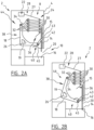
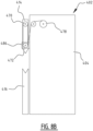
- Press brake 2 ( figure 1 ) comprises press brake frame 4.
- Press brake frame 4 has a longitudinal axis 6, which stretches out between longitudinal sides 8. Longitudinal sides 8 are substantially perpendicular to longitudinal axis 6.
- Press brake frame 4 further has front 10 where pressing element 12 is positioned.
- Pressing element 12 comprises top pressing part 14 and bottom pressing part 16.
- Top pressing part 14 and bottom pressing part 16 are both plate shaped in the press brake frame 4.
- Bottom pressing part 16 is fixed to the frame and top pressing part 14 is operatively connected to lever 18.
- Lever 18 is positioned such that the plane in which it transfers forces is substantially parallel to the plane of longitudinal sides 8.
- Lever 18 is pivotably connected to press brake frame 4 via pivot connection 26, in this example embodied as a hinge. Near pivot connection 26 lever 18 has a substantially perpendicular angle, such that a compact press brake 2 is obtained.
- Longitudinal axis 6 stretches out along the contact line between top pressing part 14 and bottom pressing part 16 when lever 18 is in press position 46.
- Height L of press brake 2 in this example is 2.5 meters.
- Longitudinal sides 8 further comprise access openings 20, such that a plate to be bent can be slid out of press brake 2 in a sideways direction.
- Electric motor 22 is operatively connected to lever 18 via pulley assembly 24.
- Pulley assembly 24 is also positioned such that it transfers forces in a substantially parallel plane of longitudinal sides 8.
- electric motor 22 is positioned in a plane substantially perpendicular to the plane of longitudinal sides 8.
- Pulley assembly 24 comprises in this example frame pulleys 30 attached to press brake frame 4, lever pulleys 32 attached to pulley carrier element 34 and connecting element 27, in this example a belt. Frame pulleys 30 and lever pulleys 32 are both placed in a line. Pulley carrier element 34 is operatively connected to first end 38 of lever 18. Lever 18 in this example further comprises support bar 19 to provide extra stability to lever 18. Connecting element 27 has been connected to electric motor 22 at motor end 28 of connecting element 27. At frame end 36 connecting element 27 has been attached to press brake frame 4.
- Connecting element 27 is alternately placed around frame pulleys 30 and lever pulleys 32, thereby providing an operative connection between electric motor 22 and lever 18 via pulley assembly 24 and pulley carrier element 34.
- lever 18 is connected via press connection 42 to top pressing part 14.
- Press connection 42 is operatively connected to second end 40 of lever 18 with first hinge connection 45 and operatively connected to top pressing part 14 with second hinge connection 43. Further shown is bottom pressing part 16.
- Lever 18 is in release position 44.
- lever pulleys 32 are positioned substantially away from frame pulleys 30.
- top pressing part 14 is therefore positioned at distance D from bottom pressing part 16. This provides the ability to position for example a steel plate on bottom pressing part 16.
- Lever 18 is positioned in press position 46 ( figure 2B ). In press position 46 of lever 18 top pressing part 14 is substantially pressed against bottom pressing part 16. In press position 46 electric motor 22 has pulled in connecting element 27 such that lever pulleys 32 have been brought towards frame pulleys 30. By pulling lever pulleys 32 towards frame pulleys 30 first end 38 of lever 18 is pulled towards frame pulleys 30, as first end 38 is operatively connected to lever pulleys 32 via pulley carrier element 34. Through pivot connection 26 and press connection 42 the movement of first end 38 of lever 18 is transferred to a substantially linear downwards movement of top pressing part 14. When for example a steel plate is placed on bottom pressing part 16, the top pressing part 14 will bend the steel plate such that it obtains a desired angle. Further provided in press brake frame 4 is guide 15 for guiding top pressing part 14 in a substantial linear downwards movement to bottom pressing part 16.
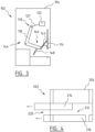
- Press brake 102 ( figure 3 ) comprises electric motor 122 attached to press brake frame 104 and operatively connected via connecting element 127 to lever 118 at first end 138 of lever 118.
- Lever 118 is pivotably connected to press brake frame 104 and at second end 140 of lever 118 operatively connected with top pressing part 114 via press connection 142.
- Press brake 102 further comprises return element 148, in this example an actuator, that is connected to second end 140 of lever 118. By providing return element 148 lever 118 will automatically return to release position 144 when it is has been brought in press position 46.
- Return element 148 could also be embodied as a spring element.
- Press brake 202 ( figure 4 ) comprises press brake frame 204 and pressing element 212.
- Pressing element 212 comprises top pressing part 214 and bottom pressing part 216.
- Top pressing part 214 and bottom pressing part 216 can be easily removed sideways through access opening 220. This provides the ability to easily replace one or more parts from pressing element 212.
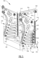
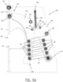
- Press brake 302 ( figure 5 ) also comprises press brake frame 304 and top pressing part 314 and bottom pressing part 316.
- motor 322 is placed substantially closer to the ground on press brake frame 304.
- frame pulleys 330 are attached to the frame and are connected via connecting element 327 to lever pulleys 332 which are attached to first end 338 of lever 318.
- Lever 318 pivots around pivot connection 326.
- Second end 340 of lever 318 is via first hinge connection 345 to press connection 342. Because press connection 342 is connected via second hinge connection 343 to top pressing part 314, by use of motor 322 first end 338 of lever 318 can be brought closer to frame pulleys 330, thereby moving top pressing part 314 down to bottom pressing element 316.
- load or weight 350 that is pivotely connected to press brake frame 304 by load pivot connection 352.
- load 350 is connected with load connecting element 356, via first load pulley 358 and second load pulley 360 to second end 340 of lever 318.
- load end 354 is moved upwards in direction D towards return element 348, which in this embodiment is spring 348.
- load 350 which in this example is counterweight 350, forms a counterweight for the top pressing part.
- return element 348 is compressed, thereby providing the counterforce to move press brake 302 back from press position 346 to release position 344.
- press brake 302 is able to move faster from press position 346 to release position 344.
- lever 18 is in release position 44.
- Electric motor 22 pulls in connecting element 27 which is alternately placed around frame pulleys 30 and lever pulleys 32. Because connecting element 27 is connected to press brake frame 4 at frame end 36, the pulling in of connecting element 27 by electric motor 22 causes lever pulleys 32 to move towards frame pulleys 30, because frame pulleys 30 are fixed on press brake frame 4.
- the movement of the lever pulleys causes first end 38 of lever 18 to move towards frame pulleys 30, because first end 38 is operatively connected to lever pulleys 32 via pulley carrier element 34. This moves lever 18 from release position 44 to press position 46.
- lever 18 transfers the movement of first end 38 to second end 40 of lever 18.
- Second end 18 transfers the movement via press connection 46 to top pressing part 14, causing top pressing part 14 to make a substantially linear downwards movement towards bottom pressing part 16, hereby bending a plate to be bend and that is placed on bottom pressing part 16.
- return element 148 provides a force on second end 40 of lever 18 such that lever 18 returns to its release position 44.
- the plate can be removed from press brake and a new plate can be provided in the opening between the pressing parts. Then a new pressing cycle of going from release position 44 to press position 46 could be started.
- Front press brake 402 ( figure 6A ) comprises front press brake frame 404.
- front press brake frame 404 front frame pulleys 472 are attached.
- pressing pulleys 470 and front frame pulleys 472 are perpendicular to the longitudinal axis 406 of front press brake 402.
- These pressing pulleys 470 are substantially provided inside top pressing part 414 and thus are at least partially positioned therein.
- front connecting element 476 which can for example be a band, a chain, a belt or a string.
- a first end 480 front connecting element 476 is connected to front motor 478, wherein front motor 478 is attached to front press brake frame 404. At second end 482 front connecting element 476 is connected to frame 404.
- Front press brake 404 in figure 6A is shown in its release position 444.
- front motor 478 is activated and shortens front connecting element 476
- front press brake 402 is brought in its press position 446 ( figure 6B ).
- By shortening front connecting element 476 pressing pulleys 470 attached on top pressing part 414 is brought towards front frame pulleys 472, thereby bringing top pressing part 414 towards bottom pressing part 416.
- FIG. 7 is a top schematic top view of front press brake 402.
- top pressing part 414 wherein holes 474 are provided such that pressing pulleys 470 can be attached substantially inside top pressing part 414.
- front frame pulleys 472 are attached on front press brake frame 404 and front connecting element 476 is alternately placed around a pressing pulley 470 and a front frame pulley 472.
- Pressing pulleys 470 and front frame pulleys 472 are provided at an angle ⁇ relative to plane P being perpendicular to longitudinal axis 406 of front press brake 402, such that a compact design of the pulley assembly is achieved.
- front frame pulleys 472 are therewith also at an angle with longitudinal axis 406, which angle is related to angle ⁇ in that the angle with longitudinal axis 406 is 90° - ⁇ .
- a design shown in figures 6A-B and figure 7 can be used as a stand alone drive of a press brake not part of the claimed invention. Furthermore, this design can also be applied on a press brake according to the figures 1 - 5 . However, the application of the design of figures 6A-B and figure 7 is not limited thereto, as it could also be used as an extra drive for any of the prior art press brakes. For example, it could be applied to a press brake making use of a hydraulic drive or with a spindle configuration.
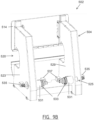
- FIGS 8A-B an alternative front press brake 402, not part of the claimed invention, is shown.
- front frame pulleys 472 provided in holes 484, which have substantially a vertical size of the path length which top pressing part 414 makes when moving from the release position to the press position.
- Having front frame pulleys 472 provided in holes 484 assures that front frame pulleys 472 are positioned substantially in the same vertical plane as pressing pulleys 470. This has the advantage that an effective and compact front press brake 402 is obtained, as the force exerted on front connecting element 476 is substantially in the same direction as the direction of front connecting element 476.
- Attached to support frame 486 ( figure 8B ) are front frame pulleys 472, wherein support frame 486 is provided in holes 484.
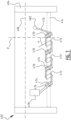
- Press brake 502 also comprises press brake frame 504 wherein top pressing part 514 and bottom pressing part 516 are provided.
- motor 522 is placed substantially closer to the ground on press brake frame 504 similar to the embodiment of figure 5 .
- frame pulleys 530 are attached to the frame and are connected via connecting element 527 to lever pulleys 532 which are attached to first end 538 of lever 518.
- Lever 518 pivots around pivot connection 526.
- Second end 540 of lever 518 is via first hinge connection 545 connected to press connection 542. Because press connection 542 is connected via second hinge connection 543 to top pressing part 514, by use of motor 522 first end 538 of lever 518 can be brought closer to frame pulleys 530, thereby moving top pressing part 514 down to bottom pressing element 516.
- return element 548 in this example embodied as a spring element.
- Return element 548 has a first end 588 that is hingeably connected to frame 504.
- Second end 590 of return element 548 is hingably connected to two support hinge elements 592 and 594.
- Support hinge element 592 is hingably connected to lever 518 through connection 593, while support hinge element 594 is hingably connected to press brake frame 504 through connection 595.
- Return element 548 and support hinge elements 592 and 594 are positioned in (an inverse) Y-shaped configuration, wherein support hinge elements 592 and 594 are the arms of the Y-shape.
- return element 548 will contract when lever 518 is brought from the release position to the press position. In the (unlikely) situation that connecting element 527 breaks, configuration lever 518 will automatically return to its release position , thereby further increasing the safety of press break 502.
- return element 548 is positioned such that the force applied on connecting element 527 is substantially constant.
- Motor 522 comprises high-speed motor 535 and low speed motor 537.
- High-speed motor 535 is in this example provided on the outer side 523 of press break frame 504.
- High-speed motor 535 is operatively connected to shaft 525 (schematically shown in figure 9b ) on which connecting element 527 is attached (not shown).
- On the inner side 529 of press break frame 504 low-speed motor 537 is attached .
- High-speed motor 535 and low-speed motor 537 are connected with each other through a magnetic coupling 531 and one-way bearing 533 as well as shaft 525.
- High-speed motor 535 and low-speed motor 537 are in this stage coupled through magnetic coupling 531.
- low-speed motor 537 takes over the drive of the downward movement of top pressing part 514. Due to the one-way bearing provided between shaft 525 and low-speed motor 537, the overtake from high-speed motor 535 to low-speed motor 537 is flawless, which means the transition occurs stop or sudden change in speed.
- Low-speed motor 537 then drives top pressing part 514 with enough force to bend metal sheets that are provided through opening 520.
- magnetic coupling 531 is uncoupled such that high-speed motor 535 moves top pressing part 514 upwards with a high speed. Due to this configuration of the drive a fast and sufficiently powerful press brake is obtained.
Landscapes
- Engineering & Computer Science (AREA)
- Mechanical Engineering (AREA)
- Bending Of Plates, Rods, And Pipes (AREA)
- Press Drives And Press Lines (AREA)
Claims (15)
- Abkantpresse (2), umfassend:- einen Abkantpressenrahmen (4);- einen Hebel (18), der an dem Rahmen (4) bewegbar angebracht ist und der zwischen einer Pressposition (46) und einer Freigabeposition (44) bewegbar ist;- einen Motor (22), der an dem Rahmen (4) und dem Hebel (18) wirkangebracht ist, wobei der Motor (22) konfiguriert ist, um den Hebel (18) zwischen der Pressposition (46) und der Freigabeposition (44) zu bewegen; und- ein pressendes Element (12), umfassend einen oberen pressenden Teil (14) und einen unteren pressenden Teil (16),wobei einer des unteren pressenden Teils (16) und des oberen pressenden Teils (14) mit dem Rahmen (4) wirkverbunden ist, wobei der andere des oberen pressenden Teils (14) und des unteren pressenden Teils (16) mit dem Hebel (18) wirkverbunden ist, und wobei der obere pressende Teil (14) und der untere pressende Teil (16) konfiguriert sind, um zusammenzupassen, wenn sich der Hebel (18) in der Pressposition (46) befindet, wobei die Abkantpresse (2) ferner eine Rollenanordnung (24) umfasst, die mit dem Motor (22) und dem Hebel (18) wirkverbunden und dazwischen positioniert ist, dadurch gekennzeichnet, dass die Rollenanordnung (24) eine Vielzahl von Rahmenrollen (30), die an dem Rahmen (4) befestigt ist, und eine Vielzahl von Hebelrollen (32) umfasst, die mit dem Hebel (18) wirkverbunden ist, wobei ein Verbindungselement (27) abwechselnd um eine Rahmenrolle (30) und eine Hebelrolle (32) herum platziert ist, und wobei das Verbindungselement (27) an einem ersten Ende des Verbindungselements (27) mit dem Motor (22) verbunden ist und an einem zweiten Ende des Verbindungselements (27) an dem Rahmen (4) befestigt ist.
- Abkantpresse (2) nach Anspruch 1, wobei der Hebel (18) mit dem Rahmen (4) schwenkbar verbunden ist und/oder wobei der Motor (22) einen Elektromotor (22) umfasst.
- Abkantpresse (2) nach Anspruch 2, wobei die Rollenanordnung (24) 2-20 Rollen, vorzugsweise 2-12 Rollen und am stärksten bevorzugt 8-10 Rollen, umfasst.
- Abkantpresse (2) nach Anspruch 3, wobei die Abkantpresse (2) ferner ein Rollenträgerelement (34) umfasst, das mit der Vielzahl von Hebelrollen (32) und dem Hebel (18) wirkverbunden ist, wobei die Hebelrollen (32) auf dem Rollenträgerelement (34) positioniert sind.
- Abkantpresse (2) nach einem der vorstehenden Ansprüche, wobei der Motor (22) einen Hochgeschwindigkeitsmotor (535) umfasst, der mit einer Welle (525) wirkverbunden ist, wobei die Welle (525) mit dem Hebel (18) zum Bewegen des Hebels (18) wirkverbunden ist, wobei der Motor (22) ferner einen Niedriggeschwindigkeitsmotor (537) umfasst, der über ein Einweglager mit der Welle (525) wirkverbunden ist.
- Abkantpresse (2) nach Anspruch 5, wobei eine lösbare Kopplung zum Koppeln des Niedriggeschwindigkeitsmotors (537) mit der Welle bereitgestellt ist, wobei vorzugsweise die lösbare Kopplung eine Magnetkopplung (531) ist.
- Abkantpresse (2) nach einem der vorstehenden Ansprüche, wobei mindestens eine Seite des Rahmens (4), die senkrecht zu einer Längsachse (6) der Abkantpresse (2) steht, eine Zugriffsöffnung zum Zugreifen auf eine zu verpressende Platte und/oder zum Ersetzen von Werkzeugen der Abkantpresse (2) aufweist.
- Abkantpresse (2) nach einem der vorstehenden Ansprüche, umfassend zwei Hebel (18), die im Wesentlichen an gegenüberliegenden Längsseiten des Rahmens (4) positioniert sind.
- Abkantpresse (2) nach Anspruch 7 oder 8, ferner umfassend einen oder mehrere Hebel (18), die bei einer Betrachtung entlang der Längsachse (6) im Wesentlichen zwischen den Längsseiten des Rahmens (4) positioniert sind.
- Abkantpresse (2) nach einem der vorstehenden Ansprüche, wobei der Hebel (18) einen Winkel umfasst, wobei der Winkel vorzugsweise in dem Bereich von 70°-135°, stärker bevorzugt in dem Bereich von 80°-135°, liegt und am stärksten bevorzugt etwa 90° beträgt.
- Abkantpresse (2) nach einem der vorstehenden Ansprüche, ferner umfassend ein Rückstellelement (148), das konfiguriert ist, um den Hebel (18) von der Pressposition in die Ruheposition zurückzustellen, wobei das Rückstellelement (148) vorzugsweise ein Federelement ist, ferner vorzugsweise umfassend eine Last (350), die an oder nahe einem ersten Ende mit dem Rahmen (4) schwenkbar verbunden ist, und die an oder nahe einem zweiten Ende davon mit dem Hebel (18) wirkverbunden ist, wobei das Gewicht der Last (350) mindestens teilweise dem Gewicht des oberen pressenden Teils (14) entgegenwirkt, und wobei die Last (350) in der Pressposition (46) auf das Federelement wirkt.
- Abkantpresse (2) nach Anspruch 11, wobei das Rückstellelement (148) ein erstes Ende und ein zweites Ende umfasst, wobei das erste Ende mit dem Rahmen (4) schwenkbar verbunden ist und ein zweites Ende mit zwei Stützscharnierelementen verbunden ist, wobei ein erstes Stützscharnierelement mit dem Hebel (18) schwenkbar verbunden ist und ein zweites Stützscharnierelement mit dem Rahmen (4) verbunden ist, wobei vorzugsweise das Rückstellelement (148) und die zwei Stützscharnierelemente in einer Y-Konfiguration positioniert sind.
- Abkantpresse (2) nach einem der vorstehenden Ansprüche, ferner umfassend:- einen Frontmotor (478), der an dem Rahmen (404) angebracht ist, vorzugsweise nahe einer Vorderseite davon; und- eine zweite Rollenanordnung, die mit dem Frontmotor wirkverbunden ist und wobei die zweite Rollenanordnung umfasst:- eine Vielzahl von vorderen Rahmenrollen (472), die an dem Rahmen (404) angebracht ist;- eine Vielzahl von pressenden Rollen (470), die mindestens teilweise innerhalb des oberen pressenden Teils (414) bereitgestellt sind, wobei die pressenden Rollen (470) mindestens in der Freigabeposition (44) im Wesentlichen über den vorderen Rahmenrollen (472) positioniert sind; und- ein vorderes Verbindungselement (476), das abwechselnd um eine vordere Rahmenrolle (472) und eine pressende Rolle (470) herum platziert ist, und wobei das vordere Verbindungselement (476) an einem ersten Ende des vorderen Verbindungselements (476) mit dem Frontmotor (478) verbunden und an einem zweiten Ende des vorderen Verbindungselements (476) an dem Rahmen (404) befestigt ist.
- Abkantpresse (2) nach Anspruch 13, wobei die Vielzahl von pressenden Rollen (470) und vordere Rahmenrollen (472) in einem Winkel relativ zu einer Ebene senkrecht zu einer Längsachse (6) der Abkantpresse (2) bereitgestellt ist.
- Verfahren zum Betreiben einer Abkantpresse (2), umfassend:- Bereitstellen einer Abkantpresse (2) nach einem der vorstehenden Ansprüche;- Bewegen des Hebels (18) von der Freigabeposition (44) in die Pressposition (46); und- Pressen einer Platte mit dem pressenden Element (12), ferner vorzugsweise umfassend:- Zurückstellen des Hebels (18) in die Freigabeposition (44), vorzugsweise unter Verwendung des Rückstellelements (148).
Applications Claiming Priority (2)
| Application Number | Priority Date | Filing Date | Title |
|---|---|---|---|
| NL2024104A NL2024104B1 (en) | 2019-10-25 | 2019-10-25 | Press brake and method for operating therefor |
| PCT/NL2020/050657 WO2021080429A1 (en) | 2019-10-25 | 2020-10-23 | Press brake and method for operating therefor |
Publications (3)
| Publication Number | Publication Date |
|---|---|
| EP4048455A1 EP4048455A1 (de) | 2022-08-31 |
| EP4048455B1 true EP4048455B1 (de) | 2024-03-20 |
| EP4048455C0 EP4048455C0 (de) | 2024-03-20 |
Family
ID=69570788
Family Applications (1)
| Application Number | Title | Priority Date | Filing Date |
|---|---|---|---|
| EP20799851.9A Active EP4048455B1 (de) | 2019-10-25 | 2020-10-23 | Abkantpresse und verfahren zum betreiben davon |
Country Status (4)
| Country | Link |
|---|---|
| US (1) | US12208437B2 (de) |
| EP (1) | EP4048455B1 (de) |
| NL (1) | NL2024104B1 (de) |
| WO (1) | WO2021080429A1 (de) |
Families Citing this family (2)
| Publication number | Priority date | Publication date | Assignee | Title |
|---|---|---|---|---|
| IT202100006950A1 (it) * | 2021-03-23 | 2022-09-23 | Exon S R L | Pressa piegatrice. |
| CN113546991A (zh) * | 2021-07-27 | 2021-10-26 | 湖北誉江船舶制造有限公司 | 一种船舶制造用折弯机 |
Family Cites Families (10)
| Publication number | Priority date | Publication date | Assignee | Title |
|---|---|---|---|---|
| US2461034A (en) * | 1945-08-29 | 1949-02-08 | Reconstruction Finance Corp | Press brake drive |
| US3719445A (en) * | 1971-05-10 | 1973-03-06 | Danly Machine Corp | Use of metal working press for plastic compression molding |
| US4030364A (en) * | 1976-05-20 | 1977-06-21 | Square D Company | Safety guard for press brakes |
| SE448686B (sv) * | 1984-07-12 | 1987-03-16 | Dahlstrom Claes Inge Sigfrid | Platpress |
| NL8900429A (nl) * | 1989-02-22 | 1990-09-17 | Safan Bv | Inrichting voor het bewerken van plaatvormig materiaal. |
| EP1203625A4 (de) * | 1999-07-13 | 2008-10-22 | Amada Co Ltd | Metallplattenbiegesystem mit biegepresse und metallplattenstützvorrichtung, kontrolldatenerzeugungsverfahren und computerlesbares speichermedium zum speichern der kontrolldaten |
| ITMI20110977A1 (it) * | 2011-05-30 | 2012-12-01 | Finn Power Italia S R L | Pressa piegatrice |
| AT514929B1 (de) * | 2013-11-26 | 2015-05-15 | Trumpf Maschinen Austria Gmbh | Werkzeugrüstsystem für Biegepresse |
| KR101738463B1 (ko) * | 2016-11-03 | 2017-05-22 | 김정환 | 전기식 절곡기 |
| CN110280635A (zh) * | 2019-07-22 | 2019-09-27 | 南京邮电大学 | 基于扭轴结构的多连杆全电伺服同步折弯机 |
-
2019
- 2019-10-25 NL NL2024104A patent/NL2024104B1/en active
-
2020
- 2020-10-23 WO PCT/NL2020/050657 patent/WO2021080429A1/en not_active Ceased
- 2020-10-23 US US17/921,584 patent/US12208437B2/en active Active
- 2020-10-23 EP EP20799851.9A patent/EP4048455B1/de active Active
Also Published As
| Publication number | Publication date |
|---|---|
| NL2024104B1 (en) | 2021-02-23 |
| US20230347399A1 (en) | 2023-11-02 |
| EP4048455A1 (de) | 2022-08-31 |
| WO2021080429A1 (en) | 2021-04-29 |
| EP4048455C0 (de) | 2024-03-20 |
| US12208437B2 (en) | 2025-01-28 |
Similar Documents
| Publication | Publication Date | Title |
|---|---|---|
| EP4048455B1 (de) | Abkantpresse und verfahren zum betreiben davon | |
| CN101367098A (zh) | 一种金属板件弯曲成型机 | |
| CA2705649A1 (en) | Mechanical press for fine blanking, forming and/or stamping of work pieces | |
| CN201324778Y (zh) | 一种金属板件弯曲成型机 | |
| CN216911599U (zh) | 偏心压紧式精密整平送料机 | |
| SK279575B6 (sk) | Ohýbací stroj na ohýbanie plechov | |
| CN211413339U (zh) | 径向热冲压成球机的成型钢球逐出装置 | |
| CN211564137U (zh) | 左右弯管机的伺服夹紧机构 | |
| CN112659377A (zh) | 夹紧装置及玻璃加工系统 | |
| CN216097332U (zh) | 立式接骨机构 | |
| CN211993594U (zh) | 夹紧装置及玻璃加工系统 | |
| CN110153301A (zh) | 一种自动缩径机 | |
| CN109500300A (zh) | 钢筋调直切断机和钢筋调直切断的方法 | |
| CN214325452U (zh) | 一种捆扎带的夹紧与切断装置 | |
| CN214720211U (zh) | 钢筋牵引机构及钢筋弯箍机 | |
| CN210098618U (zh) | 一种可调节式扁钢水平弯曲机 | |
| CN211757797U (zh) | 卡箍卷圆机 | |
| CN218224073U (zh) | 一种支撑架冷弯成型机 | |
| CN209367543U (zh) | 一种便于固定的钢材用牵引装置 | |
| CN220131600U (zh) | 一种特种合金精线加工过程中的张力调节装置 | |
| CN221312149U (zh) | 一种多冲头双连杆精密整形机台装置 | |
| CN220392449U (zh) | 一种角钢进料机构 | |
| CN220092643U (zh) | 一种钣金加工机床的预弯曲半径自动控制调节机构 | |
| CN205915032U (zh) | 直线送料杠杆压紧弯箍机 | |
| CN120394724B (zh) | 一种用于盘条加工的调直切断装置 |
Legal Events
| Date | Code | Title | Description |
|---|---|---|---|
| STAA | Information on the status of an ep patent application or granted ep patent |
Free format text: STATUS: UNKNOWN |
|
| STAA | Information on the status of an ep patent application or granted ep patent |
Free format text: STATUS: THE INTERNATIONAL PUBLICATION HAS BEEN MADE |
|
| PUAI | Public reference made under article 153(3) epc to a published international application that has entered the european phase |
Free format text: ORIGINAL CODE: 0009012 |
|
| STAA | Information on the status of an ep patent application or granted ep patent |
Free format text: STATUS: REQUEST FOR EXAMINATION WAS MADE |
|
| 17P | Request for examination filed |
Effective date: 20220524 |
|
| AK | Designated contracting states |
Kind code of ref document: A1 Designated state(s): AL AT BE BG CH CY CZ DE DK EE ES FI FR GB GR HR HU IE IS IT LI LT LU LV MC MK MT NL NO PL PT RO RS SE SI SK SM TR |
|
| DAV | Request for validation of the european patent (deleted) | ||
| DAX | Request for extension of the european patent (deleted) | ||
| GRAP | Despatch of communication of intention to grant a patent |
Free format text: ORIGINAL CODE: EPIDOSNIGR1 |
|
| STAA | Information on the status of an ep patent application or granted ep patent |
Free format text: STATUS: GRANT OF PATENT IS INTENDED |
|
| INTG | Intention to grant announced |
Effective date: 20230510 |
|
| GRAJ | Information related to disapproval of communication of intention to grant by the applicant or resumption of examination proceedings by the epo deleted |
Free format text: ORIGINAL CODE: EPIDOSDIGR1 |
|
| STAA | Information on the status of an ep patent application or granted ep patent |
Free format text: STATUS: REQUEST FOR EXAMINATION WAS MADE |
|
| INTC | Intention to grant announced (deleted) | ||
| GRAP | Despatch of communication of intention to grant a patent |
Free format text: ORIGINAL CODE: EPIDOSNIGR1 |
|
| STAA | Information on the status of an ep patent application or granted ep patent |
Free format text: STATUS: GRANT OF PATENT IS INTENDED |
|
| INTG | Intention to grant announced |
Effective date: 20231017 |
|
| GRAS | Grant fee paid |
Free format text: ORIGINAL CODE: EPIDOSNIGR3 |
|
| GRAA | (expected) grant |
Free format text: ORIGINAL CODE: 0009210 |
|
| STAA | Information on the status of an ep patent application or granted ep patent |
Free format text: STATUS: THE PATENT HAS BEEN GRANTED |
|
| AK | Designated contracting states |
Kind code of ref document: B1 Designated state(s): AL AT BE BG CH CY CZ DE DK EE ES FI FR GB GR HR HU IE IS IT LI LT LU LV MC MK MT NL NO PL PT RO RS SE SI SK SM TR |
|
| REG | Reference to a national code |
Ref country code: GB Ref legal event code: FG4D |
|
| REG | Reference to a national code |
Ref country code: CH Ref legal event code: EP |
|
| REG | Reference to a national code |
Ref country code: DE Ref legal event code: R096 Ref document number: 602020027607 Country of ref document: DE |
|
| REG | Reference to a national code |
Ref country code: IE Ref legal event code: FG4D |
|
| U01 | Request for unitary effect filed |
Effective date: 20240327 |
|
| U07 | Unitary effect registered |
Designated state(s): AT BE BG DE DK EE FI FR IT LT LU LV MT NL PT SE SI Effective date: 20240408 |
|
| PG25 | Lapsed in a contracting state [announced via postgrant information from national office to epo] |
Ref country code: GR Free format text: LAPSE BECAUSE OF FAILURE TO SUBMIT A TRANSLATION OF THE DESCRIPTION OR TO PAY THE FEE WITHIN THE PRESCRIBED TIME-LIMIT Effective date: 20240621 |
|
| PG25 | Lapsed in a contracting state [announced via postgrant information from national office to epo] |
Ref country code: HR Free format text: LAPSE BECAUSE OF FAILURE TO SUBMIT A TRANSLATION OF THE DESCRIPTION OR TO PAY THE FEE WITHIN THE PRESCRIBED TIME-LIMIT Effective date: 20240320 Ref country code: RS Free format text: LAPSE BECAUSE OF FAILURE TO SUBMIT A TRANSLATION OF THE DESCRIPTION OR TO PAY THE FEE WITHIN THE PRESCRIBED TIME-LIMIT Effective date: 20240620 |
|
| PG25 | Lapsed in a contracting state [announced via postgrant information from national office to epo] |
Ref country code: RS Free format text: LAPSE BECAUSE OF FAILURE TO SUBMIT A TRANSLATION OF THE DESCRIPTION OR TO PAY THE FEE WITHIN THE PRESCRIBED TIME-LIMIT Effective date: 20240620 Ref country code: NO Free format text: LAPSE BECAUSE OF FAILURE TO SUBMIT A TRANSLATION OF THE DESCRIPTION OR TO PAY THE FEE WITHIN THE PRESCRIBED TIME-LIMIT Effective date: 20240620 Ref country code: HR Free format text: LAPSE BECAUSE OF FAILURE TO SUBMIT A TRANSLATION OF THE DESCRIPTION OR TO PAY THE FEE WITHIN THE PRESCRIBED TIME-LIMIT Effective date: 20240320 Ref country code: GR Free format text: LAPSE BECAUSE OF FAILURE TO SUBMIT A TRANSLATION OF THE DESCRIPTION OR TO PAY THE FEE WITHIN THE PRESCRIBED TIME-LIMIT Effective date: 20240621 |
|
| PG25 | Lapsed in a contracting state [announced via postgrant information from national office to epo] |
Ref country code: IS Free format text: LAPSE BECAUSE OF FAILURE TO SUBMIT A TRANSLATION OF THE DESCRIPTION OR TO PAY THE FEE WITHIN THE PRESCRIBED TIME-LIMIT Effective date: 20240720 |
|
| PG25 | Lapsed in a contracting state [announced via postgrant information from national office to epo] |
Ref country code: SM Free format text: LAPSE BECAUSE OF FAILURE TO SUBMIT A TRANSLATION OF THE DESCRIPTION OR TO PAY THE FEE WITHIN THE PRESCRIBED TIME-LIMIT Effective date: 20240320 |
|
| PG25 | Lapsed in a contracting state [announced via postgrant information from national office to epo] |
Ref country code: ES Free format text: LAPSE BECAUSE OF FAILURE TO SUBMIT A TRANSLATION OF THE DESCRIPTION OR TO PAY THE FEE WITHIN THE PRESCRIBED TIME-LIMIT Effective date: 20240320 |
|
| PG25 | Lapsed in a contracting state [announced via postgrant information from national office to epo] |
Ref country code: CZ Free format text: LAPSE BECAUSE OF FAILURE TO SUBMIT A TRANSLATION OF THE DESCRIPTION OR TO PAY THE FEE WITHIN THE PRESCRIBED TIME-LIMIT Effective date: 20240320 |
|
| PG25 | Lapsed in a contracting state [announced via postgrant information from national office to epo] |
Ref country code: PL Free format text: LAPSE BECAUSE OF FAILURE TO SUBMIT A TRANSLATION OF THE DESCRIPTION OR TO PAY THE FEE WITHIN THE PRESCRIBED TIME-LIMIT Effective date: 20240320 |
|
| PG25 | Lapsed in a contracting state [announced via postgrant information from national office to epo] |
Ref country code: SK Free format text: LAPSE BECAUSE OF FAILURE TO SUBMIT A TRANSLATION OF THE DESCRIPTION OR TO PAY THE FEE WITHIN THE PRESCRIBED TIME-LIMIT Effective date: 20240320 |
|
| PG25 | Lapsed in a contracting state [announced via postgrant information from national office to epo] |
Ref country code: SM Free format text: LAPSE BECAUSE OF FAILURE TO SUBMIT A TRANSLATION OF THE DESCRIPTION OR TO PAY THE FEE WITHIN THE PRESCRIBED TIME-LIMIT Effective date: 20240320 Ref country code: SK Free format text: LAPSE BECAUSE OF FAILURE TO SUBMIT A TRANSLATION OF THE DESCRIPTION OR TO PAY THE FEE WITHIN THE PRESCRIBED TIME-LIMIT Effective date: 20240320 Ref country code: RO Free format text: LAPSE BECAUSE OF FAILURE TO SUBMIT A TRANSLATION OF THE DESCRIPTION OR TO PAY THE FEE WITHIN THE PRESCRIBED TIME-LIMIT Effective date: 20240320 Ref country code: PL Free format text: LAPSE BECAUSE OF FAILURE TO SUBMIT A TRANSLATION OF THE DESCRIPTION OR TO PAY THE FEE WITHIN THE PRESCRIBED TIME-LIMIT Effective date: 20240320 Ref country code: IS Free format text: LAPSE BECAUSE OF FAILURE TO SUBMIT A TRANSLATION OF THE DESCRIPTION OR TO PAY THE FEE WITHIN THE PRESCRIBED TIME-LIMIT Effective date: 20240720 Ref country code: ES Free format text: LAPSE BECAUSE OF FAILURE TO SUBMIT A TRANSLATION OF THE DESCRIPTION OR TO PAY THE FEE WITHIN THE PRESCRIBED TIME-LIMIT Effective date: 20240320 Ref country code: CZ Free format text: LAPSE BECAUSE OF FAILURE TO SUBMIT A TRANSLATION OF THE DESCRIPTION OR TO PAY THE FEE WITHIN THE PRESCRIBED TIME-LIMIT Effective date: 20240320 |
|
| U20 | Renewal fee for the european patent with unitary effect paid |
Year of fee payment: 5 Effective date: 20241028 |
|
| REG | Reference to a national code |
Ref country code: DE Ref legal event code: R097 Ref document number: 602020027607 Country of ref document: DE |
|
| PLBE | No opposition filed within time limit |
Free format text: ORIGINAL CODE: 0009261 |
|
| STAA | Information on the status of an ep patent application or granted ep patent |
Free format text: STATUS: NO OPPOSITION FILED WITHIN TIME LIMIT |
|
| 26N | No opposition filed |
Effective date: 20241223 |
|
| REG | Reference to a national code |
Ref country code: CH Ref legal event code: PL |
|
| GBPC | Gb: european patent ceased through non-payment of renewal fee |
Effective date: 20241023 |
|
| PG25 | Lapsed in a contracting state [announced via postgrant information from national office to epo] |
Ref country code: MC Free format text: LAPSE BECAUSE OF FAILURE TO SUBMIT A TRANSLATION OF THE DESCRIPTION OR TO PAY THE FEE WITHIN THE PRESCRIBED TIME-LIMIT Effective date: 20240320 |
|
| PG25 | Lapsed in a contracting state [announced via postgrant information from national office to epo] |
Ref country code: GB Free format text: LAPSE BECAUSE OF NON-PAYMENT OF DUE FEES Effective date: 20241023 |
|
| PG25 | Lapsed in a contracting state [announced via postgrant information from national office to epo] |
Ref country code: CH Free format text: LAPSE BECAUSE OF NON-PAYMENT OF DUE FEES Effective date: 20241031 |
|
| PG25 | Lapsed in a contracting state [announced via postgrant information from national office to epo] |
Ref country code: IE Free format text: LAPSE BECAUSE OF NON-PAYMENT OF DUE FEES Effective date: 20241023 |
|
| U20 | Renewal fee for the european patent with unitary effect paid |
Year of fee payment: 6 Effective date: 20251027 |
|
| PG25 | Lapsed in a contracting state [announced via postgrant information from national office to epo] |
Ref country code: CY Free format text: LAPSE BECAUSE OF FAILURE TO SUBMIT A TRANSLATION OF THE DESCRIPTION OR TO PAY THE FEE WITHIN THE PRESCRIBED TIME-LIMIT; INVALID AB INITIO Effective date: 20201023 |