EP4047276B1 - Halteschiene für flächenheizungsrohre - Google Patents
Halteschiene für flächenheizungsrohre Download PDFInfo
- Publication number
- EP4047276B1 EP4047276B1 EP22154498.4A EP22154498A EP4047276B1 EP 4047276 B1 EP4047276 B1 EP 4047276B1 EP 22154498 A EP22154498 A EP 22154498A EP 4047276 B1 EP4047276 B1 EP 4047276B1
- Authority
- EP
- European Patent Office
- Prior art keywords
- rail
- holding rail
- pipe
- longitudinal direction
- heating pipes
- Prior art date
- Legal status (The legal status is an assumption and is not a legal conclusion. Google has not performed a legal analysis and makes no representation as to the accuracy of the status listed.)
- Active
Links
Images


Classifications
-
- F—MECHANICAL ENGINEERING; LIGHTING; HEATING; WEAPONS; BLASTING
- F24—HEATING; RANGES; VENTILATING
- F24D—DOMESTIC- OR SPACE-HEATING SYSTEMS, e.g. CENTRAL HEATING SYSTEMS; DOMESTIC HOT-WATER SUPPLY SYSTEMS; ELEMENTS OR COMPONENTS THEREFOR
- F24D3/00—Hot-water central heating systems
- F24D3/12—Tube and panel arrangements for ceiling, wall, or underfloor heating
- F24D3/14—Tube and panel arrangements for ceiling, wall, or underfloor heating incorporated in a ceiling, wall or floor
- F24D3/141—Tube mountings specially adapted therefor
- F24D3/142—Tube mountings specially adapted therefor integrated in prefab construction elements
-
- F—MECHANICAL ENGINEERING; LIGHTING; HEATING; WEAPONS; BLASTING
- F24—HEATING; RANGES; VENTILATING
- F24D—DOMESTIC- OR SPACE-HEATING SYSTEMS, e.g. CENTRAL HEATING SYSTEMS; DOMESTIC HOT-WATER SUPPLY SYSTEMS; ELEMENTS OR COMPONENTS THEREFOR
- F24D3/00—Hot-water central heating systems
- F24D3/12—Tube and panel arrangements for ceiling, wall, or underfloor heating
- F24D3/14—Tube and panel arrangements for ceiling, wall, or underfloor heating incorporated in a ceiling, wall or floor
- F24D3/141—Tube mountings specially adapted therefor
-
- F—MECHANICAL ENGINEERING; LIGHTING; HEATING; WEAPONS; BLASTING
- F24—HEATING; RANGES; VENTILATING
- F24D—DOMESTIC- OR SPACE-HEATING SYSTEMS, e.g. CENTRAL HEATING SYSTEMS; DOMESTIC HOT-WATER SUPPLY SYSTEMS; ELEMENTS OR COMPONENTS THEREFOR
- F24D13/00—Electric heating systems
- F24D13/02—Electric heating systems solely using resistance heating, e.g. underfloor heating
- F24D13/022—Electric heating systems solely using resistance heating, e.g. underfloor heating resistances incorporated in construction elements
- F24D13/024—Electric heating systems solely using resistance heating, e.g. underfloor heating resistances incorporated in construction elements in walls, floors, ceilings
-
- Y—GENERAL TAGGING OF NEW TECHNOLOGICAL DEVELOPMENTS; GENERAL TAGGING OF CROSS-SECTIONAL TECHNOLOGIES SPANNING OVER SEVERAL SECTIONS OF THE IPC; TECHNICAL SUBJECTS COVERED BY FORMER USPC CROSS-REFERENCE ART COLLECTIONS [XRACs] AND DIGESTS
- Y02—TECHNOLOGIES OR APPLICATIONS FOR MITIGATION OR ADAPTATION AGAINST CLIMATE CHANGE
- Y02B—CLIMATE CHANGE MITIGATION TECHNOLOGIES RELATED TO BUILDINGS, e.g. HOUSING, HOUSE APPLIANCES OR RELATED END-USER APPLICATIONS
- Y02B30/00—Energy efficient heating, ventilation or air conditioning [HVAC]
Definitions
- the invention relates to a retaining rail for surface heating pipes according to the preamble of claim 1.
- a retaining rail is for example in EN 31 01 717 A1 disclosed.
- various support rails for the pipes carrying the heat transfer fluid are known, whereby the support rails and the pipe are embedded in a concrete casting compound that is to be hardened.
- the EP2679923B1 Support rails that comprise two longitudinal profiles that run parallel to the longitudinal direction of the rail and are spaced apart from one another and that together form several pipe holders that extend transversely to the longitudinal direction of the rail and are open at the top.
- the disadvantage of such support rails is that an even distribution of the liquid concrete casting compound is hardly achieved during embedding due to the specified rail geometry, which can lead to the formation of cavities or, in the worst case, stress cracks in the hardened concrete.
- the invention is therefore based on the object of designing a retaining rail of the type described above in such a way that, despite simple manufacturing and assembly conditions, the formation of cavities and stress cracks in the hardened concrete are largely avoided.
- the invention solves the problem with the features of claim 1.
- the invention is based on the knowledge that the flow behavior of the poured concrete can be influenced in an advantageous manner if the profile section of the holding rail assigned to the spacers runs continuously in a wave-like manner, i.e. assumes a continuous wave shape with wave humps and wave troughs, so that corners or tapered contours in particular are avoided.
- the improved flow behavior when pouring the holding rails leads to a more homogeneous distribution of the concrete casting compound in the formwork used for pouring, so that ultimately stress cracks in the hardened concrete can be largely avoided.
- the wave humps form the spacers, with the wave humps resting on the formwork in the area of the corresponding wave hump crests during the pouring process.
- the holding rail according to the invention is preferably manufactured as a one-piece plastic component.
- the distribution of the concrete casting compound is achieved while simultaneously saving rail material by limiting each pipe holder in the longitudinal direction of the rail by exactly two profile cross connectors, which each have a spring-loaded locking lug that protrudes inwards into the pipe holders.
- the profile cross connectors are preferably designed in such a way that the formation of a support surface beneath a pipe held by the pipe holder is avoided, ie that the area beneath the pipe remains free and the concrete casting compound can also flow into this free space.
- it can be provided in particular that the two longitudinal profiles running parallel in the longitudinal direction of the rail at a distance from one another are connected exclusively via the profile cross connectors, i.e. that the two longitudinal profiles are not connected via an additional longitudinal profile.
- the spacers formed by the wave humps each have a preferably cylindrical support body in the area of the wave hump crest.
- the support body can also have other cross-sectional shapes.
- the support body essentially forms a support disk. This means that the diameter of the spacer is large in comparison to its height.
- the longitudinal profiles have several fastening holes for fastening devices on the pipe support side in the longitudinal direction of the rail, in particular for fastening the retaining rail to a formwork.
- the hole axis of the fastening holes preferably runs both orthogonal to the longitudinal direction of the rail and orthogonal to the longitudinal direction of the pipe support.
- a locking connector for positively and non-positively engaging behind a locking receptacle of an adjacent holding rail can be provided at a free end of the holding rail, whereas a locking receptacle that can be positively and non-positively engaged behind by a locking connector of an adjacent holding rail is provided at the opposite free end.
- the locking connector preferably has a substantially T-shaped head, with the locking receptacle forming a corresponding T-profile.
- Holding rails according to the invention can thus be connected to one another in a simple manner by pushing them onto one another transversely to the longitudinal direction of the rail and transversely to the longitudinal direction of the pipe receptacle.
- the retaining rails according to the invention can also be used in conjunction with exposed concrete, it is proposed that the retaining rail be made of a translucent plastic. The retaining rail therefore has no inherent color and is therefore no longer visible when the concrete has hardened.
- the functionality of the holding rail according to the invention can be further increased if the longitudinal profiles on their side opposite the pipe holders comprise additional pipe holders that are open at the bottom, for example for capillary tubes, capillary tube mats and/or heating pipes equipped with an electric heater.
- additional pipe holders are preferably arranged in a trough of the wave-shaped profile section.
- the pipe holders can be formed by clamping arms attached to the longitudinal profiles and pointing downwards between two spacers.
- a support rail according to the invention can be equipped in particular with core heating pipes inserted in pipe receptacles and with surface heating pipes inserted in pipe receptacles that are open at the bottom.
- the core heating pipes are used to control the temperature of a concrete core into which the support rail is cast, in particular for heating in cold seasons and for cooling in warm seasons. In the transition period between summer and winter, when the core heating is ineffective or too slow, low-energy radiant heat can be emitted using the surface heating pipes, which are arranged particularly close to the surface.
- the surface heating pipes inserted into pipe holders that are open at the bottom can be capillary tubes, capillary tube mats and/or heating pipes equipped with an electric heater.
- the advantage of heating pipes equipped with an electric heater is that they can be operated directly with solar power if necessary.
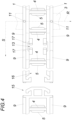
- a holding rail according to the invention comprises two longitudinal profiles 1 running parallel in the longitudinal direction S of the rail at a distance from one another.
- the longitudinal profiles 1 together form a plurality of pipe receptacles 2 which each extend transversely to the longitudinal direction S of the rail in a pipe receptacle longitudinal direction R and are open at the top for receiving, for example, surface heating pipes 3.
- each pipe receptacle 2 is delimited in the longitudinal direction S of the rail by exactly two profile cross connectors 4, each of which has a resilient locking lug 5 protruding inwards into the pipe receptacles 2.
- Each pipe receptacle 2 is thus delimited in the longitudinal direction S of the rail by locking lugs 5 protruding inwards into the pipe receptacles 2.
- the two longitudinal profiles 1 running parallel in the longitudinal direction S of the rail at a distance from one another are connected transversely to the longitudinal direction S of the rail exclusively via the profile cross connectors 4.
- the longitudinal profiles 1 each have, on their side opposite the pipe holders 2, a profile section 6 which runs uniformly undulating in the longitudinal direction S of the rail and has several wave humps 7 and several wave troughs 8.
- the wave humps 7 each form spacers 9 for specifying a distance between the pipe holders 2 and a spatial surface or a formwork 10.
- the spacers 9 formed by the wave bosses 7 each have a preferably cylindrical support body 11 in the area of the wave boss crest.
- the longitudinal profiles 1 comprise several fastening holes 12 for fastening means on the pipe receiving side in the longitudinal direction S of the rail.
- the hole axis of the fastening holes 12 runs both orthogonal to the longitudinal direction S of the rail and orthogonal to the pipe receiving longitudinal direction R.
- the longitudinal profiles also have, on their side opposite the pipe holders 2, additional pipe holders 13, which are open at the bottom, for capillary tube mats, which Fig. 2 by surface heating tubes 14, in particular a tubular capillary or the like.
- FIG.2 A retaining rail is shown schematically, which is embedded in a concrete mass of a ceiling, a wall or similar, indicated by crossed hatching. Any concrete reinforcement is obligatory, but not shown.
- the retaining rails each have a T-shaped locking connector 15 at a free end for positively and non-positively engaging behind a locking receptacle 16 of an adjacent retaining rail.
- the retaining rails each have a locking receptacle 16 at the opposite free end that can be positively and non-positively engaged behind by a locking connector 15 of an adjacent retaining rail.
- the locking connectors 15 have a substantially T-shaped head, with the locking receptacle 16 accordingly forming a corresponding T-profile. Retaining rails according to the invention can thus be connected to one another in a simple manner by pushing them onto one another transversely to the longitudinal direction S of the rail and transversely to the longitudinal direction R of the pipe receptacle.
- the pipe holders 13 are formed by clamping arms 17 attached to the longitudinal profiles 1 and pointing downwards between two spacers 9.
- the clamping arms 17 are formed on the inside or bottom of the longitudinal profiles 1 and each form a support clamped on one side.
- Each pair of these clamping arms 17 in turn forms a pipe holder 13, with the two clamping arm ends of each pipe holder 13 being bent towards each other.
- Core heating pipes namely the surface heating pipes 3, are inserted into the pipe holders 2 of the support rail, and surface heating pipes 14 are inserted into the pipe holders 13 that are open at the bottom.
- the surface heating pipes 14 used in pipe holders 13 are in particular capillary tubes, capillary tube mats ( Fig. 2 and 3 right) and/or with an electric heater ( Fig. 2 and 3 left) equipped heating pipes.
Landscapes
- Engineering & Computer Science (AREA)
- Physics & Mathematics (AREA)
- Thermal Sciences (AREA)
- Chemical & Material Sciences (AREA)
- Combustion & Propulsion (AREA)
- Mechanical Engineering (AREA)
- General Engineering & Computer Science (AREA)
- Forms Removed On Construction Sites Or Auxiliary Members Thereof (AREA)
- Railway Tracks (AREA)
- Moulds, Cores, Or Mandrels (AREA)
- Supports For Pipes And Cables (AREA)
Priority Applications (1)
| Application Number | Priority Date | Filing Date | Title |
|---|---|---|---|
| HUU2300196U HU5930U (hu) | 2021-02-22 | 2022-02-01 | Tartósín felületfûtési csövekhez |
Applications Claiming Priority (1)
| Application Number | Priority Date | Filing Date | Title |
|---|---|---|---|
| ATGM50026/2021U AT17539U1 (de) | 2021-02-22 | 2021-02-22 | Halteschiene |
Publications (2)
| Publication Number | Publication Date |
|---|---|
| EP4047276A1 EP4047276A1 (de) | 2022-08-24 |
| EP4047276B1 true EP4047276B1 (de) | 2024-05-29 |
Family
ID=80221926
Family Applications (1)
| Application Number | Title | Priority Date | Filing Date |
|---|---|---|---|
| EP22154498.4A Active EP4047276B1 (de) | 2021-02-22 | 2022-02-01 | Halteschiene für flächenheizungsrohre |
Country Status (5)
| Country | Link |
|---|---|
| EP (1) | EP4047276B1 (pl) |
| AT (1) | AT17539U1 (pl) |
| DE (1) | DE202021106881U1 (pl) |
| HU (2) | HUE067845T2 (pl) |
| PL (1) | PL4047276T3 (pl) |
Families Citing this family (2)
| Publication number | Priority date | Publication date | Assignee | Title |
|---|---|---|---|---|
| AT526536B1 (de) | 2023-07-06 | 2024-04-15 | Ke Kelit Gmbh | Halteschiene für Flächenheizungs- und/oder Flächenkühlungsrohre |
| AT527203B1 (de) | 2024-03-27 | 2024-12-15 | Ke Kelit Gmbh | Vorrichtung zum Verbinden von Halteschienen |
Family Cites Families (8)
| Publication number | Priority date | Publication date | Assignee | Title |
|---|---|---|---|---|
| DE3101717A1 (de) * | 1981-01-21 | 1982-08-26 | Artus 5060 Bergisch Gladbach Feist | Aus metallischem flachmaterial bestehende schiene zum fixieren der heizrohre einer flaechenheizung |
| DE3108573A1 (de) * | 1981-03-06 | 1982-10-28 | Risse, Ernst, 4620 Castrop-Rauxel | Kunststoffprofilleiste mit an der oberseite befestigten rohraufnahmeelementen zum verlegen und fixieren des heizungsrohres einer fussbodenheizung |
| DE50009278D1 (de) * | 2000-01-19 | 2005-02-24 | Sager Ag Duerrenaesch | Armierungs-Distanzhalter zum Verlegen einer Lage von Armierungseisen gegenüber einer Schalung für die Herstellung einer Betonkonstruktion |
| DE102004035580A1 (de) * | 2004-07-22 | 2006-02-16 | Rehau Ag + Co. | Verfahren zur Herstellung eines vorgefertigten mit Stabstahl bewehrten Bauelements, insbesondere eines Decken- oder Wandelements, mit wenigstens einer Rohrleitung zur Raumtemperierung und Halteschiene zur Verwendung bei diesem Verfahren |
| DE102005039648A1 (de) * | 2004-08-18 | 2006-03-02 | BeKa-Heiz- und Kühlmatten GmbH | Positioniermittel, Verfahren zur Herstellung und zur Einbringung eines Positioniermittels |
| AT502685B1 (de) * | 2005-11-16 | 2007-05-15 | Wavin Bv | Deckensystem zur aufnahme von kühl- oder heizrohren |
| US8695943B2 (en) * | 2009-10-29 | 2014-04-15 | Flextherm Inc. | Wire installation tool for heating wire support meshing |
| AT513069B1 (de) | 2012-06-27 | 2014-08-15 | Ke Kelit Kunststoffwerk Gmbh | Vorrichtung zum Klimatisieren eines Raumes |
-
2021
- 2021-02-22 AT ATGM50026/2021U patent/AT17539U1/de unknown
- 2021-12-17 DE DE202021106881.7U patent/DE202021106881U1/de active Active
-
2022
- 2022-02-01 HU HUE22154498A patent/HUE067845T2/hu unknown
- 2022-02-01 EP EP22154498.4A patent/EP4047276B1/de active Active
- 2022-02-01 HU HUU2300196U patent/HU5930U/hu unknown
- 2022-02-01 PL PL22154498.4T patent/PL4047276T3/pl unknown
Also Published As
| Publication number | Publication date |
|---|---|
| EP4047276A1 (de) | 2022-08-24 |
| HUE067845T2 (hu) | 2024-11-28 |
| PL4047276T3 (pl) | 2024-09-30 |
| AT17539U1 (de) | 2022-07-15 |
| DE202021106881U1 (de) | 2022-01-20 |
| HU5930U (hu) | 2025-09-28 |
Similar Documents
| Publication | Publication Date | Title |
|---|---|---|
| EP1770337A1 (de) | Noppenplatte mit Zwischennoppen | |
| EP4047276A1 (de) | Halteschiene für flächenheizungsrohre | |
| EP2466028B1 (de) | Bauelement mit Rohrleitungen und Verfahren zur Herstellung eines Bauelementes | |
| DE3109866C2 (de) | Verlegeplatte zum flächigen Verlegen von Rohrleitungen, insbesondere bei einer Fußbodenheizung | |
| EP0074490A2 (de) | Fussboden mit integrierter Warmwasser-Fussbodenheizung | |
| DE102007055134A1 (de) | Baufertigelement mit Kühl-/Heizfunktion sowie Decken-Kühl-/Heizsystem | |
| DE4108524A1 (de) | Vorrichtung zur installation von rohren oder schlaeuchen | |
| AT513069A1 (de) | Vorrichtung zum Klimatisieren eines Raumes | |
| DE3425019A1 (de) | Bodenplatte fuer einen aufgestaenderten boden und aus solchen bodenplatten gebildeter boden | |
| DE102014110843B4 (de) | Flächentemperierungselement sowie aus mehreren Flächentemperierungselementen bestehender Flächentemperierungsaufbau | |
| WO1983000544A1 (en) | Installation for tempering a room | |
| DE4201552A1 (de) | Wandverkleidungselement | |
| DE102011114684B4 (de) | Rohrträger für ein Flächentemperiersystem in Betonböden, -wänden und -decken | |
| DE10060971C1 (de) | Deckenelement | |
| EP1719852B1 (de) | Abstandshalter für ein Bewehrungselement eines Stahlbeton-Bauteils, insbesondere einer Stahlbetondecke | |
| EP3869108B1 (de) | Fussbodenheizungssystem | |
| EP0267146B1 (de) | Armierungskorb | |
| DE10253867A1 (de) | Vorrichtung zum Austausch von Wärme und/oder Kälte mit Feststoffen oder Feststoffgemischen und Verfahren zur Herstellung eines Beton- oder Ortbetonteils | |
| CH665667A5 (de) | Isolierplattenanordnung. | |
| DE19735258C2 (de) | Haltegitter zum Halten eines Rohres für eine Flächenheizung oder Flächenkühlung mit gebogenen und geradlinigen Abschnitten | |
| DE102009037064B4 (de) | Absorber zum Erwärmen eines Fluids | |
| AT13655U1 (de) | Kühldeckenelement | |
| DE10259961A1 (de) | Vorgefertigtes Bauelement, insbesondere Decken- oder Wandbauelement aus einem ausgehärteten Material sowie Verfahren zur Herstellung eines solchen Bauelements | |
| AT411914B (de) | Belagsplatte | |
| DE202004015984U1 (de) | Gittermatte und Fertigelementdecke mit einer Gittermatte |
Legal Events
| Date | Code | Title | Description |
|---|---|---|---|
| PUAI | Public reference made under article 153(3) epc to a published international application that has entered the european phase |
Free format text: ORIGINAL CODE: 0009012 |
|
| STAA | Information on the status of an ep patent application or granted ep patent |
Free format text: STATUS: THE APPLICATION HAS BEEN PUBLISHED |
|
| AK | Designated contracting states |
Kind code of ref document: A1 Designated state(s): AL AT BE BG CH CY CZ DE DK EE ES FI FR GB GR HR HU IE IS IT LI LT LU LV MC MK MT NL NO PL PT RO RS SE SI SK SM TR |
|
| STAA | Information on the status of an ep patent application or granted ep patent |
Free format text: STATUS: REQUEST FOR EXAMINATION WAS MADE |
|
| 17P | Request for examination filed |
Effective date: 20230123 |
|
| RBV | Designated contracting states (corrected) |
Designated state(s): AL AT BE BG CH CY CZ DE DK EE ES FI FR GB GR HR HU IE IS IT LI LT LU LV MC MK MT NL NO PL PT RO RS SE SI SK SM TR |
|
| GRAP | Despatch of communication of intention to grant a patent |
Free format text: ORIGINAL CODE: EPIDOSNIGR1 |
|
| STAA | Information on the status of an ep patent application or granted ep patent |
Free format text: STATUS: GRANT OF PATENT IS INTENDED |
|
| INTG | Intention to grant announced |
Effective date: 20240306 |
|
| GRAS | Grant fee paid |
Free format text: ORIGINAL CODE: EPIDOSNIGR3 |
|
| GRAA | (expected) grant |
Free format text: ORIGINAL CODE: 0009210 |
|
| STAA | Information on the status of an ep patent application or granted ep patent |
Free format text: STATUS: THE PATENT HAS BEEN GRANTED |
|
| AK | Designated contracting states |
Kind code of ref document: B1 Designated state(s): AL AT BE BG CH CY CZ DE DK EE ES FI FR GB GR HR HU IE IS IT LI LT LU LV MC MK MT NL NO PL PT RO RS SE SI SK SM TR |
|
| REG | Reference to a national code |
Ref country code: CH Ref legal event code: EP |
|
| REG | Reference to a national code |
Ref country code: IE Ref legal event code: FG4D Free format text: LANGUAGE OF EP DOCUMENT: GERMAN |
|
| REG | Reference to a national code |
Ref country code: DE Ref legal event code: R096 Ref document number: 502022000940 Country of ref document: DE |
|
| REG | Reference to a national code |
Ref country code: NL Ref legal event code: FP |
|
| REG | Reference to a national code |
Ref country code: LT Ref legal event code: MG9D |
|
| PG25 | Lapsed in a contracting state [announced via postgrant information from national office to epo] |
Ref country code: IS Free format text: LAPSE BECAUSE OF FAILURE TO SUBMIT A TRANSLATION OF THE DESCRIPTION OR TO PAY THE FEE WITHIN THE PRESCRIBED TIME-LIMIT Effective date: 20240929 |
|
| PG25 | Lapsed in a contracting state [announced via postgrant information from national office to epo] |
Ref country code: BG Free format text: LAPSE BECAUSE OF FAILURE TO SUBMIT A TRANSLATION OF THE DESCRIPTION OR TO PAY THE FEE WITHIN THE PRESCRIBED TIME-LIMIT Effective date: 20240529 |
|
| REG | Reference to a national code |
Ref country code: SK Ref legal event code: T3 Ref document number: E 44726 Country of ref document: SK |
|
| PG25 | Lapsed in a contracting state [announced via postgrant information from national office to epo] |
Ref country code: HR Free format text: LAPSE BECAUSE OF FAILURE TO SUBMIT A TRANSLATION OF THE DESCRIPTION OR TO PAY THE FEE WITHIN THE PRESCRIBED TIME-LIMIT Effective date: 20240529 Ref country code: FI Free format text: LAPSE BECAUSE OF FAILURE TO SUBMIT A TRANSLATION OF THE DESCRIPTION OR TO PAY THE FEE WITHIN THE PRESCRIBED TIME-LIMIT Effective date: 20240529 |
|
| PG25 | Lapsed in a contracting state [announced via postgrant information from national office to epo] |
Ref country code: GR Free format text: LAPSE BECAUSE OF FAILURE TO SUBMIT A TRANSLATION OF THE DESCRIPTION OR TO PAY THE FEE WITHIN THE PRESCRIBED TIME-LIMIT Effective date: 20240830 |
|
| PG25 | Lapsed in a contracting state [announced via postgrant information from national office to epo] |
Ref country code: ES Free format text: LAPSE BECAUSE OF FAILURE TO SUBMIT A TRANSLATION OF THE DESCRIPTION OR TO PAY THE FEE WITHIN THE PRESCRIBED TIME-LIMIT Effective date: 20240529 |
|
| PG25 | Lapsed in a contracting state [announced via postgrant information from national office to epo] |
Ref country code: LV Free format text: LAPSE BECAUSE OF FAILURE TO SUBMIT A TRANSLATION OF THE DESCRIPTION OR TO PAY THE FEE WITHIN THE PRESCRIBED TIME-LIMIT Effective date: 20240529 |
|
| PG25 | Lapsed in a contracting state [announced via postgrant information from national office to epo] |
Ref country code: NO Free format text: LAPSE BECAUSE OF FAILURE TO SUBMIT A TRANSLATION OF THE DESCRIPTION OR TO PAY THE FEE WITHIN THE PRESCRIBED TIME-LIMIT Effective date: 20240829 Ref country code: LV Free format text: LAPSE BECAUSE OF FAILURE TO SUBMIT A TRANSLATION OF THE DESCRIPTION OR TO PAY THE FEE WITHIN THE PRESCRIBED TIME-LIMIT Effective date: 20240529 Ref country code: IS Free format text: LAPSE BECAUSE OF FAILURE TO SUBMIT A TRANSLATION OF THE DESCRIPTION OR TO PAY THE FEE WITHIN THE PRESCRIBED TIME-LIMIT Effective date: 20240929 Ref country code: HR Free format text: LAPSE BECAUSE OF FAILURE TO SUBMIT A TRANSLATION OF THE DESCRIPTION OR TO PAY THE FEE WITHIN THE PRESCRIBED TIME-LIMIT Effective date: 20240529 Ref country code: GR Free format text: LAPSE BECAUSE OF FAILURE TO SUBMIT A TRANSLATION OF THE DESCRIPTION OR TO PAY THE FEE WITHIN THE PRESCRIBED TIME-LIMIT Effective date: 20240830 Ref country code: FI Free format text: LAPSE BECAUSE OF FAILURE TO SUBMIT A TRANSLATION OF THE DESCRIPTION OR TO PAY THE FEE WITHIN THE PRESCRIBED TIME-LIMIT Effective date: 20240529 Ref country code: ES Free format text: LAPSE BECAUSE OF FAILURE TO SUBMIT A TRANSLATION OF THE DESCRIPTION OR TO PAY THE FEE WITHIN THE PRESCRIBED TIME-LIMIT Effective date: 20240529 Ref country code: BG Free format text: LAPSE BECAUSE OF FAILURE TO SUBMIT A TRANSLATION OF THE DESCRIPTION OR TO PAY THE FEE WITHIN THE PRESCRIBED TIME-LIMIT Effective date: 20240529 Ref country code: RS Free format text: LAPSE BECAUSE OF FAILURE TO SUBMIT A TRANSLATION OF THE DESCRIPTION OR TO PAY THE FEE WITHIN THE PRESCRIBED TIME-LIMIT Effective date: 20240829 |
|
| REG | Reference to a national code |
Ref country code: HU Ref legal event code: AG4A Ref document number: E067845 Country of ref document: HU |
|
| PG25 | Lapsed in a contracting state [announced via postgrant information from national office to epo] |
Ref country code: DK Free format text: LAPSE BECAUSE OF FAILURE TO SUBMIT A TRANSLATION OF THE DESCRIPTION OR TO PAY THE FEE WITHIN THE PRESCRIBED TIME-LIMIT Effective date: 20240529 |
|
| PG25 | Lapsed in a contracting state [announced via postgrant information from national office to epo] |
Ref country code: EE Free format text: LAPSE BECAUSE OF FAILURE TO SUBMIT A TRANSLATION OF THE DESCRIPTION OR TO PAY THE FEE WITHIN THE PRESCRIBED TIME-LIMIT Effective date: 20240529 |
|
| PG25 | Lapsed in a contracting state [announced via postgrant information from national office to epo] |
Ref country code: CZ Free format text: LAPSE BECAUSE OF FAILURE TO SUBMIT A TRANSLATION OF THE DESCRIPTION OR TO PAY THE FEE WITHIN THE PRESCRIBED TIME-LIMIT Effective date: 20240529 |
|
| PG25 | Lapsed in a contracting state [announced via postgrant information from national office to epo] |
Ref country code: RO Free format text: LAPSE BECAUSE OF FAILURE TO SUBMIT A TRANSLATION OF THE DESCRIPTION OR TO PAY THE FEE WITHIN THE PRESCRIBED TIME-LIMIT Effective date: 20240529 |
|
| PG25 | Lapsed in a contracting state [announced via postgrant information from national office to epo] |
Ref country code: SM Free format text: LAPSE BECAUSE OF FAILURE TO SUBMIT A TRANSLATION OF THE DESCRIPTION OR TO PAY THE FEE WITHIN THE PRESCRIBED TIME-LIMIT Effective date: 20240529 |
|
| PG25 | Lapsed in a contracting state [announced via postgrant information from national office to epo] |
Ref country code: SM Free format text: LAPSE BECAUSE OF FAILURE TO SUBMIT A TRANSLATION OF THE DESCRIPTION OR TO PAY THE FEE WITHIN THE PRESCRIBED TIME-LIMIT Effective date: 20240529 Ref country code: RO Free format text: LAPSE BECAUSE OF FAILURE TO SUBMIT A TRANSLATION OF THE DESCRIPTION OR TO PAY THE FEE WITHIN THE PRESCRIBED TIME-LIMIT Effective date: 20240529 Ref country code: EE Free format text: LAPSE BECAUSE OF FAILURE TO SUBMIT A TRANSLATION OF THE DESCRIPTION OR TO PAY THE FEE WITHIN THE PRESCRIBED TIME-LIMIT Effective date: 20240529 Ref country code: DK Free format text: LAPSE BECAUSE OF FAILURE TO SUBMIT A TRANSLATION OF THE DESCRIPTION OR TO PAY THE FEE WITHIN THE PRESCRIBED TIME-LIMIT Effective date: 20240529 Ref country code: CZ Free format text: LAPSE BECAUSE OF FAILURE TO SUBMIT A TRANSLATION OF THE DESCRIPTION OR TO PAY THE FEE WITHIN THE PRESCRIBED TIME-LIMIT Effective date: 20240529 |
|
| REG | Reference to a national code |
Ref country code: DE Ref legal event code: R097 Ref document number: 502022000940 Country of ref document: DE |
|
| PLBE | No opposition filed within time limit |
Free format text: ORIGINAL CODE: 0009261 |
|
| STAA | Information on the status of an ep patent application or granted ep patent |
Free format text: STATUS: NO OPPOSITION FILED WITHIN TIME LIMIT |
|
| PG25 | Lapsed in a contracting state [announced via postgrant information from national office to epo] |
Ref country code: SI Free format text: LAPSE BECAUSE OF FAILURE TO SUBMIT A TRANSLATION OF THE DESCRIPTION OR TO PAY THE FEE WITHIN THE PRESCRIBED TIME-LIMIT Effective date: 20240529 |
|
| 26N | No opposition filed |
Effective date: 20250303 |
|
| P01 | Opt-out of the competence of the unified patent court (upc) registered |
Free format text: CASE NUMBER: APP_17217/2025 Effective date: 20250409 |
|
| PG25 | Lapsed in a contracting state [announced via postgrant information from national office to epo] |
Ref country code: SE Free format text: LAPSE BECAUSE OF FAILURE TO SUBMIT A TRANSLATION OF THE DESCRIPTION OR TO PAY THE FEE WITHIN THE PRESCRIBED TIME-LIMIT Effective date: 20240529 |
|
| PG25 | Lapsed in a contracting state [announced via postgrant information from national office to epo] |
Ref country code: MC Free format text: LAPSE BECAUSE OF FAILURE TO SUBMIT A TRANSLATION OF THE DESCRIPTION OR TO PAY THE FEE WITHIN THE PRESCRIBED TIME-LIMIT Effective date: 20240529 |
|
| PG25 | Lapsed in a contracting state [announced via postgrant information from national office to epo] |
Ref country code: LU Free format text: LAPSE BECAUSE OF NON-PAYMENT OF DUE FEES Effective date: 20250201 |
|
| REG | Reference to a national code |
Ref country code: BE Ref legal event code: MM Effective date: 20250228 |
|
| PG25 | Lapsed in a contracting state [announced via postgrant information from national office to epo] |
Ref country code: BE Free format text: LAPSE BECAUSE OF NON-PAYMENT OF DUE FEES Effective date: 20250228 |
|
| PG25 | Lapsed in a contracting state [announced via postgrant information from national office to epo] |
Ref country code: IE Free format text: LAPSE BECAUSE OF NON-PAYMENT OF DUE FEES Effective date: 20250201 |
|
| REG | Reference to a national code |
Ref country code: CH Ref legal event code: U11 Free format text: ST27 STATUS EVENT CODE: U-0-0-U10-U11 (AS PROVIDED BY THE NATIONAL OFFICE) Effective date: 20260301 |
|
| PGFP | Annual fee paid to national office [announced via postgrant information from national office to epo] |
Ref country code: NL Payment date: 20260220 Year of fee payment: 5 |
|
| PGFP | Annual fee paid to national office [announced via postgrant information from national office to epo] |
Ref country code: HU Payment date: 20260211 Year of fee payment: 5 |
|
| PGFP | Annual fee paid to national office [announced via postgrant information from national office to epo] |
Ref country code: DE Payment date: 20260213 Year of fee payment: 5 |
|
| PGFP | Annual fee paid to national office [announced via postgrant information from national office to epo] |
Ref country code: AT Payment date: 20260301 Year of fee payment: 5 |
|
| PGFP | Annual fee paid to national office [announced via postgrant information from national office to epo] |
Ref country code: IT Payment date: 20260220 Year of fee payment: 5 |
|
| PGFP | Annual fee paid to national office [announced via postgrant information from national office to epo] |
Ref country code: FR Payment date: 20260224 Year of fee payment: 5 |
|
| PGFP | Annual fee paid to national office [announced via postgrant information from national office to epo] |
Ref country code: CH Payment date: 20260301 Year of fee payment: 5 |
|
| PGFP | Annual fee paid to national office [announced via postgrant information from national office to epo] |
Ref country code: PL Payment date: 20260122 Year of fee payment: 5 |
|
| PGFP | Annual fee paid to national office [announced via postgrant information from national office to epo] |
Ref country code: SK Payment date: 20260123 Year of fee payment: 5 |