EP4047237B1 - Kupplungsstruktur - Google Patents
Kupplungsstruktur Download PDFInfo
- Publication number
- EP4047237B1 EP4047237B1 EP22156244.0A EP22156244A EP4047237B1 EP 4047237 B1 EP4047237 B1 EP 4047237B1 EP 22156244 A EP22156244 A EP 22156244A EP 4047237 B1 EP4047237 B1 EP 4047237B1
- Authority
- EP
- European Patent Office
- Prior art keywords
- push
- unit
- clutch structure
- structure according
- input shaft
- Prior art date
- Legal status (The legal status is an assumption and is not a legal conclusion. Google has not performed a legal analysis and makes no representation as to the accuracy of the status listed.)
- Active
Links
Images


Classifications
-
- F—MECHANICAL ENGINEERING; LIGHTING; HEATING; WEAPONS; BLASTING
- F16—ENGINEERING ELEMENTS AND UNITS; GENERAL MEASURES FOR PRODUCING AND MAINTAINING EFFECTIVE FUNCTIONING OF MACHINES OR INSTALLATIONS; THERMAL INSULATION IN GENERAL
- F16D—COUPLINGS FOR TRANSMITTING ROTATION; CLUTCHES; BRAKES
- F16D23/00—Details of mechanically-actuated clutches not specific for one distinct type
- F16D23/12—Mechanical clutch-actuating mechanisms arranged outside the clutch as such
-
- F—MECHANICAL ENGINEERING; LIGHTING; HEATING; WEAPONS; BLASTING
- F16—ENGINEERING ELEMENTS AND UNITS; GENERAL MEASURES FOR PRODUCING AND MAINTAINING EFFECTIVE FUNCTIONING OF MACHINES OR INSTALLATIONS; THERMAL INSULATION IN GENERAL
- F16D—COUPLINGS FOR TRANSMITTING ROTATION; CLUTCHES; BRAKES
- F16D13/00—Friction clutches
- F16D13/22—Friction clutches with axially-movable clutching members
- F16D13/38—Friction clutches with axially-movable clutching members with flat clutching surfaces, e.g. discs
- F16D13/52—Clutches with multiple lamellae ; Clutches in which three or more axially moveable members are fixed alternately to the shafts to be coupled and are pressed from one side towards an axially-located member
-
- F—MECHANICAL ENGINEERING; LIGHTING; HEATING; WEAPONS; BLASTING
- F16—ENGINEERING ELEMENTS AND UNITS; GENERAL MEASURES FOR PRODUCING AND MAINTAINING EFFECTIVE FUNCTIONING OF MACHINES OR INSTALLATIONS; THERMAL INSULATION IN GENERAL
- F16D—COUPLINGS FOR TRANSMITTING ROTATION; CLUTCHES; BRAKES
- F16D13/00—Friction clutches
- F16D13/58—Details
- F16D13/60—Clutching elements
- F16D13/64—Clutch-plates; Clutch-lamellae
- F16D13/648—Clutch-plates; Clutch-lamellae for clutches with multiple lamellae
-
- F—MECHANICAL ENGINEERING; LIGHTING; HEATING; WEAPONS; BLASTING
- F16—ENGINEERING ELEMENTS AND UNITS; GENERAL MEASURES FOR PRODUCING AND MAINTAINING EFFECTIVE FUNCTIONING OF MACHINES OR INSTALLATIONS; THERMAL INSULATION IN GENERAL
- F16D—COUPLINGS FOR TRANSMITTING ROTATION; CLUTCHES; BRAKES
- F16D13/00—Friction clutches
- F16D13/58—Details
- F16D13/70—Pressure members, e.g. pressure plates, for clutch-plates or lamellae; Guiding arrangements for pressure members
-
- F—MECHANICAL ENGINEERING; LIGHTING; HEATING; WEAPONS; BLASTING
- F16—ENGINEERING ELEMENTS AND UNITS; GENERAL MEASURES FOR PRODUCING AND MAINTAINING EFFECTIVE FUNCTIONING OF MACHINES OR INSTALLATIONS; THERMAL INSULATION IN GENERAL
- F16D—COUPLINGS FOR TRANSMITTING ROTATION; CLUTCHES; BRAKES
- F16D28/00—Electrically-actuated clutches
-
- F—MECHANICAL ENGINEERING; LIGHTING; HEATING; WEAPONS; BLASTING
- F16—ENGINEERING ELEMENTS AND UNITS; GENERAL MEASURES FOR PRODUCING AND MAINTAINING EFFECTIVE FUNCTIONING OF MACHINES OR INSTALLATIONS; THERMAL INSULATION IN GENERAL
- F16D—COUPLINGS FOR TRANSMITTING ROTATION; CLUTCHES; BRAKES
- F16D13/00—Friction clutches
- F16D13/58—Details
- F16D13/70—Pressure members, e.g. pressure plates, for clutch-plates or lamellae; Guiding arrangements for pressure members
- F16D2013/706—Pressure members, e.g. pressure plates, for clutch-plates or lamellae; Guiding arrangements for pressure members the axially movable pressure plate is supported by leaf springs
-
- F—MECHANICAL ENGINEERING; LIGHTING; HEATING; WEAPONS; BLASTING
- F16—ENGINEERING ELEMENTS AND UNITS; GENERAL MEASURES FOR PRODUCING AND MAINTAINING EFFECTIVE FUNCTIONING OF MACHINES OR INSTALLATIONS; THERMAL INSULATION IN GENERAL
- F16D—COUPLINGS FOR TRANSMITTING ROTATION; CLUTCHES; BRAKES
- F16D23/00—Details of mechanically-actuated clutches not specific for one distinct type
- F16D23/12—Mechanical clutch-actuating mechanisms arranged outside the clutch as such
- F16D2023/123—Clutch actuation by cams, ramps or ball-screw mechanisms
-
- F—MECHANICAL ENGINEERING; LIGHTING; HEATING; WEAPONS; BLASTING
- F16—ENGINEERING ELEMENTS AND UNITS; GENERAL MEASURES FOR PRODUCING AND MAINTAINING EFFECTIVE FUNCTIONING OF MACHINES OR INSTALLATIONS; THERMAL INSULATION IN GENERAL
- F16D—COUPLINGS FOR TRANSMITTING ROTATION; CLUTCHES; BRAKES
- F16D2125/00—Components of actuators
- F16D2125/18—Mechanical mechanisms
- F16D2125/20—Mechanical mechanisms converting rotation to linear movement or vice versa
- F16D2125/34—Mechanical mechanisms converting rotation to linear movement or vice versa acting in the direction of the axis of rotation
- F16D2125/36—Helical cams, Ball-rotating ramps
-
- F—MECHANICAL ENGINEERING; LIGHTING; HEATING; WEAPONS; BLASTING
- F16—ENGINEERING ELEMENTS AND UNITS; GENERAL MEASURES FOR PRODUCING AND MAINTAINING EFFECTIVE FUNCTIONING OF MACHINES OR INSTALLATIONS; THERMAL INSULATION IN GENERAL
- F16D—COUPLINGS FOR TRANSMITTING ROTATION; CLUTCHES; BRAKES
- F16D2125/00—Components of actuators
- F16D2125/18—Mechanical mechanisms
- F16D2125/44—Mechanical mechanisms transmitting rotation
- F16D2125/46—Rotating members in mutual engagement
- F16D2125/52—Rotating members in mutual engagement with non-parallel stationary axes, e.g. worm or bevel gears
Definitions
- the present invention relates generally to a clutch, and more particularly to a clutch that has a simplified structure and thus a reduced size for easy installation in a narrow space.
- Existing frictional clutches involve various different designs of actuation members, among which the most commonly seen are electromagnetic type and hydraulic type.
- the electromagnetic type needs to arrange an electromagnetic valve, electrical components, and electrical wires inside the clutch, such that the structure is complicated and the widthwise dimension is large.
- the clutching power is essentially induced by an electromagnetic force, so that the force acting on clutch plates is limited and thus the clutching power of the clutch plates is relatively weak.
- the hydraulic type it needs to arrange hydraulic fluid channels in the clutch, such as hydraulic fluid passages formed in a rotary shaft. This not only makes the structure extremely sophisticated but also suffers hydraulic fluid related deficiencies in relation to compression ratio and quality deterioration, and would result in issues of instability of pressing force.
- Taiwan Patent Application No. 105129499 which includes an external drive assembly that drives a driving disc and a driven disc to move, in a radial direction, a pushing member, so that the pushing member causes lining plates to combine together for moving a driven member on a driven side.
- the size is affected by the external drive assembly to have an enlarged overall width, and this is disadvantageous for installation and application in a narrow space.
- contact engagement induced between the pushing member and the lining plates that are rotated in unison with a transmission shaft may easily experience pause and setback, leading to a delay of transmission and thus affecting operability and reliability thereof.
- Further exemplary clutch constructions can be seen in US 2018/073573 A1 and US 6988604 B2 .
- the primary objective of the present invention is to realize structure simplification and effective reduction of size so as to be easily installed and applied in a narrow space.
- a second objective of the present invention is to effectively reduce pause and setback in coupling and connection and also to efficiently establish a transmission clutching force so as not have the operability affected by pause and setback.
- an additional objective of the present invention is to provide an acting force for pushing that is realized through mechanical direct pushing, so that the torque is made large and positive drivability and reliability are enhanced.
- the present invention relates to a clutch structure that functions to transmit a rotation driving power to a driven side.
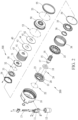
- the clutch structure comprises a stationary casing 10, an input shaft 15, an actuation unit 200, a push unit 300, a clutching unit 40, and an output casing 50 that serves as the driven side.
- the input shaft 15 is driven by the rotation driving power and is rotatably mounted inside the stationary casing 10 by means of the actuation unit 200.
- the push unit 300, the clutching unit 40, and the output casing 50 are arranged, in sequence, on the input shaft 15 so that the push unit 300 that is mounted on the input shaft 15 is operable to selectively drive the clutching unit 40 to realize a clutching operation thereby allowing the input shaft 15 to selectively transmit the rotation driving power to the output casing 50.
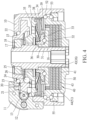
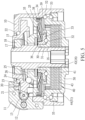
- FIGS. 2 , 3 , and 4 Details of the clutch structure are shown in FIGS. 2 , 3 , and 4 , wherein the stationary casing 10 is provided with a through opening 101 formed in an outer circumference thereof and communicating between inside and outside, for receiving a motor 12 of which an output shaft is connected to a worm 13 to mount thereto to have the worm 13 engage with the actuation unit 200 arranged in the interior of the casing.
- the stationary casing 10 is provided with a protection lid 11 mounted thereto at a location corresponding to the through opening 101.
- the input shaft 15 is formed, in an end thereof corresponding to an open end of the stationary casing 10, with a plurality of external spline teeth 16 that extend in an axial direction, and the input shaft 15 is provided, on an opposite end thereof, with a shaft coupling section 17, which is extended into and arranged, as being rotatably supported by a bearing 18, in a center of the actuation unit 200 inside the stationary casing 10.
- the actuation unit 200 comprises a rotary disc 20 that is rotatably mounted on the bearing 18 of the input shaft 15 and a push disc 25.
- a group of balls 22 is interposed between the rotary disc 20 and the stationary casing 10, so that the rotary disc 20 is rotatable, in a stable and smooth manner, inside the stationary casing 10 and relative to the input shaft 15 and the stationary casing 10.
- the rotary disc 20 has a circumference that is formed with a worm gear 21 engageable with the worm 13 of the motor 12, so that the motor 12 is operable to selectively drive the rotary disc 20 to rotate clockwise or counterclockwise.
- the rotary disc 20 is formed, in a side surface thereof corresponding to the push disc 25, with at least two roller channels 23 that are equally spaced, and the push disc 25 is also formed, in a surface thereof, with at least two corresponding roller channels 26, wherein each pair of corresponding roller channels 23, 26 interpose a roller 24 therebetween so that the rotary disc 20, when set in rotation, may selectively cause the push disc 25 to move away or to retract backward.
- the push unit 300 is arranged on the input shaft 15, and the push unit 300 comprises a push bracket 30, a spring holder 33, and a bowl-shaped spring plate 35, wherein the push bracket 30 has a central inner circumference that is formed with a plurality of internal spline teeth 31 corresponding to the external spline teeth 16 of the input shaft 15, to allow the push bracket 30 to selectively contact and push against the clutching unit 40 and also to rotate in unison with the input shaft 15.
- the spring holder 33 is arranged on an axle part of the push bracket 30, and a group of balls 32 is interposed between the spring holder 33 and the push bracket 30 to keep smooth rotation of the push bracket 30.
- a constraint ring 34 that has an inside diameter smaller than an outside diameter of the spring holder 33 is fixed to the push bracket 30 to constrain the spring holder 33 on the push bracket 30 for not detaching therefrom.
- the bowl-shaped spring plate 35 is mounted by a nut 36 to have an inner circumference fixed to the spring holder 33, while an outer circumference of the bowl-shaped spring plate 35 is retained on the push disc 25 arranged on an opposite side, so that the bowl-shaped spring plate 35 may provide a restoration preloading force when the push unit 300 is subjected to pushing by the push disc 25 of the actuation unit 200.
- the push unit 300 includes a compression spring 38 of which an end is supported on one side of the push disc 25 that corresponds to the bowl-shaped spring plate 35, and a stop ring 39 is arranged in the interior of the stationary casing 10 to support an opposite end of the compression spring 38 in order to generate, with respect to the push disc 25, a spare restoration preloading force and also to help overcome tolerance of assembly to make the movement or operation of the push disc 25 smoother.
- the clutching unit 40 is formed a plurality of first lining plates 41 and a plurality of second lining plates 43 that are alternately arranged in a spaced manner, wherein the first lining plates 41 have a central inner circumference that is formed with internal spline teeth 42 corresponding to the external spline teeth 16 of the input shaft 15; the first lining plates 41 are set in free rotation relative to the output casing 50; central inner circumferences of the second lining plates 43 are set in free rotation relative to the input shaft 15; and outer circumferences of the second lining plates 43 are formed with a plurality of external spline teeth 44 in mating engagement with the output casing 50.
- the output casing 50 is rotatably mounted to the stationary casing 10 by means of groups of balls 52, 53 respectively arranged on two sides thereof and is restrained on the stationary casing 10 by means of a lock ring cover 55. Further, the output casing 50 is formed, in an inner circumference thereof, with a plurality of internal spline teeth 51 corresponding to the external spline teeth 44 of the second lining plates 43, so that the output casing 50 is drivable by the second lining plates 43 of the clutching unit 40 to rotate relative to the stationary casing 10.
- FIG. 4 An actual application of the present invention is illustrated in FIG. 4 .
- the motor 12 drives, by means of the worm 13, the rotary disc 20 of the actuation unit 200 to an inactive position, where the rollers 24 are caused to deeply move into the interior of the roller channels 23, 26 between the rotary disc 20 and the push disc 25 to allow the push disc 25 to be forced backward simultaneously by the bowl-shaped spring plate 35 and the compression spring 38 of the push unit 300, so that the clutching unit 40 is not pushed by the push bracket 30 of the push unit 300, and consequently, adjacent ones of the first and second lining plates 41, 43 of the clutching unit 40 are not kept in frictional engagement with each other and the rotation driving power is not transmitted through the input shaft 15 and the clutching unit 40 to the output casing 50, and therefore, the output casing 50 remains fixed.
- the clutching unit 40 is thus subjected to pressing by the spring holder 33 and the push bracket 30 of the push unit 300, and adjacent ones of the first and second lining plates 41, 43 of the clutching unit 40 are set in contact and engagement with each other so that a frictional force induced between the two achieves coupling therebetween to allow the rotation driving power to transmit through the input shaft 15 and the clutching unit 40 to the output casing 50, and consequently, the output casing 50 is thus driven.
- the present invention provides an arrangement in which the clutch structure directly drives, by means of the motor 12, the rotary disc 20 of the actuation unit 200, and the actuation unit 200 is further allowed to directly drive or act on the push unit 300, so that the structure is effectively simplified and the size is reduced, allowing for easy installation and application in a narrow space.
- the spring holder 33 of the push unit 300 drives the push bracket 30 to press against the clutching unit 40, the push bracket 30 and the clutching unit 40 are set in synchronous rotation with respect to each other, and the push bracket 30 and the spring holder 33 are provided therebetween with the group of balls 32, so that the rotation can be kept smooth even during the process of pressing.
- the clutch structure of the present invention uses a driving action force that is provided as mechanical direct pushing, so that the torque is made large and positive drivability and reliability are enhanced.
Landscapes
- Engineering & Computer Science (AREA)
- General Engineering & Computer Science (AREA)
- Mechanical Engineering (AREA)
- Physics & Mathematics (AREA)
- Electromagnetism (AREA)
- Mechanical Operated Clutches (AREA)
- Braking Arrangements (AREA)
- Friction Gearing (AREA)
- One-Way And Automatic Clutches, And Combinations Of Different Clutches (AREA)
Claims (12)
- Kupplungsstruktur, die Folgendes umfasst:ein stationäres Gehäuse (10), das einen Außenumfang aufweist, an dem ein Motor (12) montiert wird, wobei der Motor (12) eine Schnecke (13) umfasst, die sich in ein Inneres des stationären Gehäuses (10) erstreckt;eine Betätigungseinheit (200), die im Inneren des stationären Gehäuses (10) angebracht ist, wobei die Betätigungseinheit (200) eine Drehscheibe (20) und eine Schubscheibe (25) umfasst, wobei die Drehscheibe (20) einen Umfang aufweist, der mit einem Schneckengetriebe (21) in passendem Eingriff mit der Schnecke (13) ausgebildet ist, wobei mindestens zwei Rollen (24) zwischen der Drehscheibe (20) und der Schubscheibe (25) angeordnet sind und gleichmäßig voneinander beabstandet sind;eine Eingangswelle (15), die sich drehbar in eine Mitte der Drehscheibe (20) der Betätigungseinheit (200) erstreckt;eine Schiebeeinheit (300), die an der Eingangswelle (15) montiert ist, wobei die Schiebeeinheit (300) einen Schiebebügel (30), einen Federhalter (33), und eine napfförmige Federplatte (35) umfasst, wobei der Schiebebügel (30) mit der Eingangswelle (15) in einer Weise verbunden ist, dass er in Bezug auf diese parallel verschiebbar und synchron drehbar ist, wobei die Federplatte (33) drehbar auf dem Schiebebügel (30) angeordnet ist, wobei die napfförmige Federplatte (35) zwischen dem Federhalter (33) und der Schubscheibe (25) getragen wird;eine Kupplungseinheit (40), die auf der Eingangswelle (15) an einer Seite derselben angeordnet ist, die an die Schiebeeinheit (300) angrenzt, wobei die Kupplungseinheit (40) eine Vielzahl von ersten Belagplatten (41) und eine Vielzahl von zweiten Belagplatten (43) umfasst, die abwechselnd in einer beabstandeten Weise angeordnet sind, wobei die ersten Belagplatten (41) mit der Eingangswelle (15) derart gekoppelt sind, dass sie parallel verschiebbar und synchron dazu drehbar sind, und die zweiten Belagplatten (43) so angeordnet sind, dass sie in Bezug auf die Eingangswelle (15) drehbar sind; undein Ausgabegehäuse (50), das drehbar im Inneren des stationären Gehäuses (10) an einer Seite desselben montiert ist, die an die Kupplungseinheit (40) angrenzt, wobei das Ausgabegehäuse (50) mit den zweiten Belagplatten (43) in einer Weise gekoppelt ist, dass es parallel verschiebbar und synchron dazu drehbar ist.
- Kupplungsstruktur nach Anspruch 1, wobei das stationäre Gehäuse (10) einen Außenumfang aufweist, in dem eine mit dem Inneren und dem Äußeren kommunizierende Durchgangsöffnung (101) gebildet wird, um die Schnecke (13) des Motors (12) zu empfangen, die dadurch verläuft, und das stationäre Gehäuse (10) mit einem Schutzdeckel (11) versehen ist, der auf einer der Durchgangsöffnung (101) entsprechenden Position darauf montiert ist.
- Kupplungsstruktur nach Anspruch 1, wobei eine Gruppe von Kugeln (22) zwischen der Drehscheibe (20) und dem stationären Gehäuse (10) der Betätigungseinheit (200) eingefügt ist.
- Kupplungsstruktur nach Anspruch 1, wobei die Drehscheibe (20) und die Schubscheibe (25) der Betätigungseinheit (200) aneinander gewandte Oberflächen aufweisen und mit mindestens zwei Rollenkanälen (23, 26) gebildet werden, die, zum jeweiligen Empfangen der dazwischen einzufügenden Rollen (24) gleichmäßig beabstandet sind.
- Kupplungsstruktur nach Anspruch 1, wobei die Eingangswelle (15) ein Ende aufweist, das der Drehscheibe (20) der Betätigungseinheit (200) entspricht und mit einem Wellenkupplungsquerschnitt (17) gebildet ist, der durch ein Lager (18) gestützt ist, um sich in eine Mitte der Drehscheibe (20) zu erstrecken.
- Kupplungsstruktur nach Anspruch 1 oder 5, wobei die Eingangswelle (15) einen Außenumfang aufweist, der, in einem Teil entsprechend der Schiebeeinheit (300) und der Kupplungseinheit (40) gebildet ist, mit einer Vielzahl von sich in axialer Richtung Außenverzahnungen (16) ausgebildet ist, und ein zentraler Innenumfang des Schiebebügels (30) der Schiebeeinheit (300) mit einer Vielzahl von damit korrespondierenden inneren Keilverzahnungen (31) ausgebildet ist, und ein zentraler Innenumfang der ersten Belagplatten (41) der Kupplungseinheit (40) auch mit einer Vielzahl von damit korrespondierenden inneren Keilverzahnungen (42) ausgebildet ist.
- Kupplungsstruktur nach Anspruch 6, wobei ein Außenumfang der zweiten Belagplatten (43) der Kupplungseinheit (40) mit einer Vielzahl von äußeren Keilverzahnungen (44) ausgebildet ist, und ein Innenumfang des Ausgabegehäuses (50) mit einer Vielzahl von damit korrespondierenden inneren Keilverzahnungen (51) ausgebildet ist.
- Kupplungsstruktur nach Anspruch 1, wobei eine Gruppe von Kugeln (32) zwischen dem Federhalter (33) und dem Schiebebügel (30) eingefügt ist.
- Kupplungsstruktur nach Anspruch 1, wobei ein Beschränkungsring (34) von welchem ein Innendurchmesser kleiner als ein Außendurchmesser des Federhalters (33) ist, an dem Schiebebügel (30) der Schiebeeinheit (300) befestigt ist.
- Kupplungsstruktur nach Anspruch 1, wobei die napfförmige Federplatte (35) der Schiebeeinheit (300) durch eine Mutter (36) montiert wird, indem ein Innenumfang an dem Federhalter (33) befestigt ist, und ein Außenumfang der napfförmigen Federplatte (35) auf der Schubscheibe (25) an einer gegenüberliegenden Seite festgelegt ist.
- Kupplungsstruktur nach Anspruch 1 oder 10, wobei die Schiebeeinheit (300) eine Druckfeder (38) umfasst, von welcher ein Ende an einer Seite der Schubscheibe (25) gestützt wird, die der napfförmigen Federplatte (35) entspricht, und ein Anschlagring (39) im Inneren des stationären Gehäuses (10) angebracht ist, um ein gegenüberliegendes Ende der Druckfeder (38) abzustützen.
- Kupplungsstruktur nach Anspruch 1, wobei das Ausgabegehäuse (50) drehbar an dem stationären Gehäuse (10) mittels Gruppen von Kugeln (52, 53) montiert ist, die auf zwei Seiten davon angebracht sind, und auf dem stationären Gehäuse (10) mittels eines Verschlussringdeckels (55) gehalten wird.
Applications Claiming Priority (1)
| Application Number | Priority Date | Filing Date | Title |
|---|---|---|---|
| TW110106140A TWI757100B (zh) | 2021-02-22 | 2021-02-22 | 離合器結構 |
Publications (3)
| Publication Number | Publication Date |
|---|---|
| EP4047237A1 EP4047237A1 (de) | 2022-08-24 |
| EP4047237B1 true EP4047237B1 (de) | 2024-03-27 |
| EP4047237C0 EP4047237C0 (de) | 2024-03-27 |
Family
ID=80447620
Family Applications (1)
| Application Number | Title | Priority Date | Filing Date |
|---|---|---|---|
| EP22156244.0A Active EP4047237B1 (de) | 2021-02-22 | 2022-02-11 | Kupplungsstruktur |
Country Status (5)
| Country | Link |
|---|---|
| US (1) | US11614128B2 (de) |
| EP (1) | EP4047237B1 (de) |
| JP (2) | JP3237187U (de) |
| CN (2) | CN114962480A (de) |
| TW (1) | TWI757100B (de) |
Families Citing this family (1)
| Publication number | Priority date | Publication date | Assignee | Title |
|---|---|---|---|---|
| TWI757100B (zh) * | 2021-02-22 | 2022-03-01 | 姚立和 | 離合器結構 |
Family Cites Families (15)
| Publication number | Priority date | Publication date | Assignee | Title |
|---|---|---|---|---|
| US6874609B2 (en) * | 2002-11-25 | 2005-04-05 | General Motors Corporation | Rotary-to-linear transfer device |
| US6988604B2 (en) * | 2004-04-19 | 2006-01-24 | Borgwarner Inc. | Friction clutch pack having a motor driven ball ramp operator |
| JP2005351463A (ja) * | 2004-06-14 | 2005-12-22 | Tochigi Fuji Ind Co Ltd | 加圧アクチュエータ、トルク伝達カップリング、四輪駆動車 |
| JP2007170632A (ja) * | 2005-12-26 | 2007-07-05 | Hitachi Ltd | 回転軸の軸方向位置の変動に非干渉のクラッチ機構 |
| US8231492B2 (en) * | 2009-04-16 | 2012-07-31 | GM Global Technology Operations LLC | Torque transmitting device |
| DE102011077748A1 (de) * | 2011-06-17 | 2012-12-20 | Zf Friedrichshafen Ag | Verbindungsvorrichtung für außerhalb eines Zahnräderwechselgetriebes |
| KR20140147439A (ko) * | 2013-06-20 | 2014-12-30 | 현경열 | 다판 클러치 |
| CN107636353B (zh) * | 2015-10-06 | 2020-06-09 | 吉凯恩传动系统日本株式会社 | 末级驱动器 |
| WO2017081749A1 (ja) * | 2015-11-10 | 2017-05-18 | Gkn ドライブライン ジャパン株式会社 | 脱連結可能なパワートランスファユニット |
| TWI632306B (zh) * | 2016-09-10 | 2018-08-11 | 本土股份有限公司 | Clutch structure |
| JP6418218B2 (ja) * | 2016-10-06 | 2018-11-07 | トヨタ自動車株式会社 | 車両用差動制限装置 |
| KR102020104B1 (ko) * | 2017-05-10 | 2019-11-05 | 이티알 주식회사 | 클리어런스 제어 사판 장치 및 마찰 클러치 적용 단일 축 2속 구동 시스템 |
| WO2020009192A1 (ja) * | 2018-07-06 | 2020-01-09 | 株式会社デンソー | クラッチ装置 |
| JP2020193696A (ja) | 2019-05-30 | 2020-12-03 | 株式会社Ijtt | トランスファー |
| TWI757100B (zh) * | 2021-02-22 | 2022-03-01 | 姚立和 | 離合器結構 |
-
2021
- 2021-02-22 TW TW110106140A patent/TWI757100B/zh active
-
2022
- 2022-01-24 CN CN202210078212.6A patent/CN114962480A/zh active Pending
- 2022-01-24 CN CN202220182879.6U patent/CN217401489U/zh active Active
- 2022-01-26 US US17/585,488 patent/US11614128B2/en active Active
- 2022-02-11 EP EP22156244.0A patent/EP4047237B1/de active Active
- 2022-02-19 JP JP2022000504U patent/JP3237187U/ja active Active
- 2022-02-19 JP JP2022024343A patent/JP7450952B2/ja active Active
Also Published As
| Publication number | Publication date |
|---|---|
| US11614128B2 (en) | 2023-03-28 |
| TWI757100B (zh) | 2022-03-01 |
| CN217401489U (zh) | 2022-09-09 |
| JP7450952B2 (ja) | 2024-03-18 |
| JP3237187U (ja) | 2022-04-19 |
| US20220268322A1 (en) | 2022-08-25 |
| TW202233975A (zh) | 2022-09-01 |
| EP4047237A1 (de) | 2022-08-24 |
| CN114962480A (zh) | 2022-08-30 |
| EP4047237C0 (de) | 2024-03-27 |
| JP2022128433A (ja) | 2022-09-01 |
Similar Documents
| Publication | Publication Date | Title |
|---|---|---|
| JP4372997B2 (ja) | バリエータ変速装置 | |
| CN106715944B (zh) | 动力传递装置 | |
| US10670085B2 (en) | Automatic clutch device | |
| US20070144861A1 (en) | Clutch mechanism free from influence of axial displacement of rotary member | |
| CN103975172B (zh) | 离合器驱动器 | |
| CN101865218B (zh) | 扭矩传递装置 | |
| EP3099953A1 (de) | Reibungskupplung mit doppelverstärkung | |
| EP4047237B1 (de) | Kupplungsstruktur | |
| CN110864079B (zh) | 一种平地机用蜗轮箱及平地机 | |
| JP5097932B2 (ja) | 密閉式混練機のシール構造 | |
| JPH08226451A (ja) | 軸連結機構 | |
| US12390916B2 (en) | Power tool and clutch assembly thereof | |
| JP2017057872A (ja) | 自動クラッチ装置 | |
| CN216045100U (zh) | 串联式湿式双离合器 | |
| JP4513158B2 (ja) | 摩擦ローラ式変速機 | |
| CN108775347A (zh) | 一种组合式离合器 | |
| CN221145094U (zh) | 新能源汽车用离合器 | |
| CN113700769B (zh) | 串联式湿式双离合器 | |
| CN220764354U (zh) | 进给机构周向限位的电子机械制动装置和车辆 | |
| JP2554096Y2 (ja) | クラッチ装置 | |
| JP4839553B2 (ja) | 摩擦ローラ式変速機及び原動機付摩擦ローラ式変速機 | |
| JP2025064510A (ja) | クラッチユニット | |
| JP2003176856A (ja) | 電動減速機 | |
| KR20050047982A (ko) | 자동 변속기의 클러치 장치 | |
| KR20250074118A (ko) | 전자기계 브레이크 액추에이터 |
Legal Events
| Date | Code | Title | Description |
|---|---|---|---|
| PUAI | Public reference made under article 153(3) epc to a published international application that has entered the european phase |
Free format text: ORIGINAL CODE: 0009012 |
|
| STAA | Information on the status of an ep patent application or granted ep patent |
Free format text: STATUS: THE APPLICATION HAS BEEN PUBLISHED |
|
| AK | Designated contracting states |
Kind code of ref document: A1 Designated state(s): AL AT BE BG CH CY CZ DE DK EE ES FI FR GB GR HR HU IE IS IT LI LT LU LV MC MK MT NL NO PL PT RO RS SE SI SK SM TR |
|
| STAA | Information on the status of an ep patent application or granted ep patent |
Free format text: STATUS: REQUEST FOR EXAMINATION WAS MADE |
|
| 17P | Request for examination filed |
Effective date: 20230202 |
|
| RBV | Designated contracting states (corrected) |
Designated state(s): AL AT BE BG CH CY CZ DE DK EE ES FI FR GB GR HR HU IE IS IT LI LT LU LV MC MK MT NL NO PL PT RO RS SE SI SK SM TR |
|
| GRAP | Despatch of communication of intention to grant a patent |
Free format text: ORIGINAL CODE: EPIDOSNIGR1 |
|
| RIC1 | Information provided on ipc code assigned before grant |
Ipc: F16D 23/12 20060101ALI20230728BHEP Ipc: F16D 28/00 20060101AFI20230728BHEP |
|
| STAA | Information on the status of an ep patent application or granted ep patent |
Free format text: STATUS: GRANT OF PATENT IS INTENDED |
|
| INTG | Intention to grant announced |
Effective date: 20230907 |
|
| GRAS | Grant fee paid |
Free format text: ORIGINAL CODE: EPIDOSNIGR3 |
|
| GRAA | (expected) grant |
Free format text: ORIGINAL CODE: 0009210 |
|
| STAA | Information on the status of an ep patent application or granted ep patent |
Free format text: STATUS: THE PATENT HAS BEEN GRANTED |
|
| AK | Designated contracting states |
Kind code of ref document: B1 Designated state(s): AL AT BE BG CH CY CZ DE DK EE ES FI FR GB GR HR HU IE IS IT LI LT LU LV MC MK MT NL NO PL PT RO RS SE SI SK SM TR |
|
| REG | Reference to a national code |
Ref country code: GB Ref legal event code: FG4D |
|
| REG | Reference to a national code |
Ref country code: CH Ref legal event code: EP |
|
| REG | Reference to a national code |
Ref country code: DE Ref legal event code: R096 Ref document number: 602022002489 Country of ref document: DE |
|
| REG | Reference to a national code |
Ref country code: IE Ref legal event code: FG4D |
|
| U01 | Request for unitary effect filed |
Effective date: 20240422 |
|
| U07 | Unitary effect registered |
Designated state(s): AT BE BG DE DK EE FI FR IT LT LU LV MT NL PT SE SI Effective date: 20240527 |
|
| PG25 | Lapsed in a contracting state [announced via postgrant information from national office to epo] |
Ref country code: GR Free format text: LAPSE BECAUSE OF FAILURE TO SUBMIT A TRANSLATION OF THE DESCRIPTION OR TO PAY THE FEE WITHIN THE PRESCRIBED TIME-LIMIT Effective date: 20240628 |
|
| PG25 | Lapsed in a contracting state [announced via postgrant information from national office to epo] |
Ref country code: HR Free format text: LAPSE BECAUSE OF FAILURE TO SUBMIT A TRANSLATION OF THE DESCRIPTION OR TO PAY THE FEE WITHIN THE PRESCRIBED TIME-LIMIT Effective date: 20240327 Ref country code: RS Free format text: LAPSE BECAUSE OF FAILURE TO SUBMIT A TRANSLATION OF THE DESCRIPTION OR TO PAY THE FEE WITHIN THE PRESCRIBED TIME-LIMIT Effective date: 20240627 |
|
| PG25 | Lapsed in a contracting state [announced via postgrant information from national office to epo] |
Ref country code: RS Free format text: LAPSE BECAUSE OF FAILURE TO SUBMIT A TRANSLATION OF THE DESCRIPTION OR TO PAY THE FEE WITHIN THE PRESCRIBED TIME-LIMIT Effective date: 20240627 Ref country code: NO Free format text: LAPSE BECAUSE OF FAILURE TO SUBMIT A TRANSLATION OF THE DESCRIPTION OR TO PAY THE FEE WITHIN THE PRESCRIBED TIME-LIMIT Effective date: 20240627 Ref country code: HR Free format text: LAPSE BECAUSE OF FAILURE TO SUBMIT A TRANSLATION OF THE DESCRIPTION OR TO PAY THE FEE WITHIN THE PRESCRIBED TIME-LIMIT Effective date: 20240327 Ref country code: GR Free format text: LAPSE BECAUSE OF FAILURE TO SUBMIT A TRANSLATION OF THE DESCRIPTION OR TO PAY THE FEE WITHIN THE PRESCRIBED TIME-LIMIT Effective date: 20240628 |
|
| PG25 | Lapsed in a contracting state [announced via postgrant information from national office to epo] |
Ref country code: IS Free format text: LAPSE BECAUSE OF FAILURE TO SUBMIT A TRANSLATION OF THE DESCRIPTION OR TO PAY THE FEE WITHIN THE PRESCRIBED TIME-LIMIT Effective date: 20240727 |
|
| PG25 | Lapsed in a contracting state [announced via postgrant information from national office to epo] |
Ref country code: SM Free format text: LAPSE BECAUSE OF FAILURE TO SUBMIT A TRANSLATION OF THE DESCRIPTION OR TO PAY THE FEE WITHIN THE PRESCRIBED TIME-LIMIT Effective date: 20240327 |
|
| PG25 | Lapsed in a contracting state [announced via postgrant information from national office to epo] |
Ref country code: ES Free format text: LAPSE BECAUSE OF FAILURE TO SUBMIT A TRANSLATION OF THE DESCRIPTION OR TO PAY THE FEE WITHIN THE PRESCRIBED TIME-LIMIT Effective date: 20240327 |
|
| PG25 | Lapsed in a contracting state [announced via postgrant information from national office to epo] |
Ref country code: CZ Free format text: LAPSE BECAUSE OF FAILURE TO SUBMIT A TRANSLATION OF THE DESCRIPTION OR TO PAY THE FEE WITHIN THE PRESCRIBED TIME-LIMIT Effective date: 20240327 |
|
| PG25 | Lapsed in a contracting state [announced via postgrant information from national office to epo] |
Ref country code: PL Free format text: LAPSE BECAUSE OF FAILURE TO SUBMIT A TRANSLATION OF THE DESCRIPTION OR TO PAY THE FEE WITHIN THE PRESCRIBED TIME-LIMIT Effective date: 20240327 |
|
| PG25 | Lapsed in a contracting state [announced via postgrant information from national office to epo] |
Ref country code: SK Free format text: LAPSE BECAUSE OF FAILURE TO SUBMIT A TRANSLATION OF THE DESCRIPTION OR TO PAY THE FEE WITHIN THE PRESCRIBED TIME-LIMIT Effective date: 20240327 |
|
| PG25 | Lapsed in a contracting state [announced via postgrant information from national office to epo] |
Ref country code: SM Free format text: LAPSE BECAUSE OF FAILURE TO SUBMIT A TRANSLATION OF THE DESCRIPTION OR TO PAY THE FEE WITHIN THE PRESCRIBED TIME-LIMIT Effective date: 20240327 Ref country code: SK Free format text: LAPSE BECAUSE OF FAILURE TO SUBMIT A TRANSLATION OF THE DESCRIPTION OR TO PAY THE FEE WITHIN THE PRESCRIBED TIME-LIMIT Effective date: 20240327 Ref country code: RO Free format text: LAPSE BECAUSE OF FAILURE TO SUBMIT A TRANSLATION OF THE DESCRIPTION OR TO PAY THE FEE WITHIN THE PRESCRIBED TIME-LIMIT Effective date: 20240327 Ref country code: PL Free format text: LAPSE BECAUSE OF FAILURE TO SUBMIT A TRANSLATION OF THE DESCRIPTION OR TO PAY THE FEE WITHIN THE PRESCRIBED TIME-LIMIT Effective date: 20240327 Ref country code: IS Free format text: LAPSE BECAUSE OF FAILURE TO SUBMIT A TRANSLATION OF THE DESCRIPTION OR TO PAY THE FEE WITHIN THE PRESCRIBED TIME-LIMIT Effective date: 20240727 Ref country code: ES Free format text: LAPSE BECAUSE OF FAILURE TO SUBMIT A TRANSLATION OF THE DESCRIPTION OR TO PAY THE FEE WITHIN THE PRESCRIBED TIME-LIMIT Effective date: 20240327 Ref country code: CZ Free format text: LAPSE BECAUSE OF FAILURE TO SUBMIT A TRANSLATION OF THE DESCRIPTION OR TO PAY THE FEE WITHIN THE PRESCRIBED TIME-LIMIT Effective date: 20240327 |
|
| REG | Reference to a national code |
Ref country code: DE Ref legal event code: R097 Ref document number: 602022002489 Country of ref document: DE |
|
| PLBE | No opposition filed within time limit |
Free format text: ORIGINAL CODE: 0009261 |
|
| STAA | Information on the status of an ep patent application or granted ep patent |
Free format text: STATUS: NO OPPOSITION FILED WITHIN TIME LIMIT |
|
| U20 | Renewal fee for the european patent with unitary effect paid |
Year of fee payment: 4 Effective date: 20250117 |
|
| 26N | No opposition filed |
Effective date: 20250103 |
|
| PG25 | Lapsed in a contracting state [announced via postgrant information from national office to epo] |
Ref country code: MC Free format text: LAPSE BECAUSE OF FAILURE TO SUBMIT A TRANSLATION OF THE DESCRIPTION OR TO PAY THE FEE WITHIN THE PRESCRIBED TIME-LIMIT Effective date: 20240327 |
|
| REG | Reference to a national code |
Ref country code: CH Ref legal event code: PL |
|
| PG25 | Lapsed in a contracting state [announced via postgrant information from national office to epo] |
Ref country code: CH Free format text: LAPSE BECAUSE OF NON-PAYMENT OF DUE FEES Effective date: 20250228 |