EP4047232B1 - Federgeführtes doppel-kardangelenk - Google Patents
Federgeführtes doppel-kardangelenk Download PDFInfo
- Publication number
- EP4047232B1 EP4047232B1 EP22156173.1A EP22156173A EP4047232B1 EP 4047232 B1 EP4047232 B1 EP 4047232B1 EP 22156173 A EP22156173 A EP 22156173A EP 4047232 B1 EP4047232 B1 EP 4047232B1
- Authority
- EP
- European Patent Office
- Prior art keywords
- input
- output
- yoke
- cross
- resilient member
- Prior art date
- Legal status (The legal status is an assumption and is not a legal conclusion. Google has not performed a legal analysis and makes no representation as to the accuracy of the status listed.)
- Active
Links
Images



Classifications
-
- F—MECHANICAL ENGINEERING; LIGHTING; HEATING; WEAPONS; BLASTING
- F16—ENGINEERING ELEMENTS AND UNITS; GENERAL MEASURES FOR PRODUCING AND MAINTAINING EFFECTIVE FUNCTIONING OF MACHINES OR INSTALLATIONS; THERMAL INSULATION IN GENERAL
- F16D—COUPLINGS FOR TRANSMITTING ROTATION; CLUTCHES; BRAKES
- F16D3/00—Yielding couplings, i.e. with means permitting movement between the connected parts during the drive
- F16D3/50—Yielding couplings, i.e. with means permitting movement between the connected parts during the drive with the coupling parts connected by one or more intermediate members
- F16D3/52—Yielding couplings, i.e. with means permitting movement between the connected parts during the drive with the coupling parts connected by one or more intermediate members comprising a continuous strip, spring, or the like engaging the coupling parts at a number of places
-
- F—MECHANICAL ENGINEERING; LIGHTING; HEATING; WEAPONS; BLASTING
- F16—ENGINEERING ELEMENTS AND UNITS; GENERAL MEASURES FOR PRODUCING AND MAINTAINING EFFECTIVE FUNCTIONING OF MACHINES OR INSTALLATIONS; THERMAL INSULATION IN GENERAL
- F16D—COUPLINGS FOR TRANSMITTING ROTATION; CLUTCHES; BRAKES
- F16D3/00—Yielding couplings, i.e. with means permitting movement between the connected parts during the drive
- F16D3/16—Universal joints in which flexibility is produced by means of pivots or sliding or rolling connecting parts
- F16D3/26—Hooke's joints or other joints with an equivalent intermediate member to which each coupling part is pivotally or slidably connected
- F16D3/30—Hooke's joints or other joints with an equivalent intermediate member to which each coupling part is pivotally or slidably connected in which the coupling is specially adapted to constant velocity-ratio
- F16D3/32—Hooke's joints or other joints with an equivalent intermediate member to which each coupling part is pivotally or slidably connected in which the coupling is specially adapted to constant velocity-ratio by the provision of two intermediate members each having two relatively perpendicular trunnions or bearings
-
- F—MECHANICAL ENGINEERING; LIGHTING; HEATING; WEAPONS; BLASTING
- F16—ENGINEERING ELEMENTS AND UNITS; GENERAL MEASURES FOR PRODUCING AND MAINTAINING EFFECTIVE FUNCTIONING OF MACHINES OR INSTALLATIONS; THERMAL INSULATION IN GENERAL
- F16D—COUPLINGS FOR TRANSMITTING ROTATION; CLUTCHES; BRAKES
- F16D3/00—Yielding couplings, i.e. with means permitting movement between the connected parts during the drive
- F16D3/16—Universal joints in which flexibility is produced by means of pivots or sliding or rolling connecting parts
- F16D3/26—Hooke's joints or other joints with an equivalent intermediate member to which each coupling part is pivotally or slidably connected
- F16D3/38—Hooke's joints or other joints with an equivalent intermediate member to which each coupling part is pivotally or slidably connected with a single intermediate member with trunnions or bearings arranged on two axes perpendicular to one another
- F16D3/40—Hooke's joints or other joints with an equivalent intermediate member to which each coupling part is pivotally or slidably connected with a single intermediate member with trunnions or bearings arranged on two axes perpendicular to one another with intermediate member provided with two pairs of outwardly-directed trunnions on intersecting axes
- F16D3/405—Apparatus for assembling or dismantling
-
- F—MECHANICAL ENGINEERING; LIGHTING; HEATING; WEAPONS; BLASTING
- F16—ENGINEERING ELEMENTS AND UNITS; GENERAL MEASURES FOR PRODUCING AND MAINTAINING EFFECTIVE FUNCTIONING OF MACHINES OR INSTALLATIONS; THERMAL INSULATION IN GENERAL
- F16D—COUPLINGS FOR TRANSMITTING ROTATION; CLUTCHES; BRAKES
- F16D3/00—Yielding couplings, i.e. with means permitting movement between the connected parts during the drive
- F16D3/50—Yielding couplings, i.e. with means permitting movement between the connected parts during the drive with the coupling parts connected by one or more intermediate members
- F16D3/64—Yielding couplings, i.e. with means permitting movement between the connected parts during the drive with the coupling parts connected by one or more intermediate members comprising elastic elements arranged between substantially-radial walls of both coupling parts
-
- Y—GENERAL TAGGING OF NEW TECHNOLOGICAL DEVELOPMENTS; GENERAL TAGGING OF CROSS-SECTIONAL TECHNOLOGIES SPANNING OVER SEVERAL SECTIONS OF THE IPC; TECHNICAL SUBJECTS COVERED BY FORMER USPC CROSS-REFERENCE ART COLLECTIONS [XRACs] AND DIGESTS
- Y10—TECHNICAL SUBJECTS COVERED BY FORMER USPC
- Y10S—TECHNICAL SUBJECTS COVERED BY FORMER USPC CROSS-REFERENCE ART COLLECTIONS [XRACs] AND DIGESTS
- Y10S464/00—Rotary shafts, gudgeons, housings, and flexible couplings for rotary shafts
- Y10S464/904—Homokinetic coupling
- Y10S464/905—Torque transmitted via radially extending pin
Definitions
- the present invention relates generally to the automotive field. More particularly, the present invention relates to a double cardan joint for coupling two drive shafts together and that includes a spring component positioned between two universal joints and that is adapted to guide and center the double cardan joint to maintain a bend of the double cardan joint in the middle thereof and to keep the bend angle divided between the two universal joints.
- Double cardan joints are adapted to transfer rotation between two non-parallel shafts.
- FIG. 1 which illustrates a conventional double cardan joint 100
- the conventional double cardan joint 100 includes two universal joints connected between an input shaft 10 and an output shaft 20.
- the conventional double cardan joint 100 includes an input yoke 110 connected to a center yoke 130 (often referred to as an H yoke) via an input cross-member 115 (forming a first universal joint) and an output yoke 120 connected to the center yoke 130 via an output cross-member 125 (forming a second universal joint).
- the conventional double cardan joint 100 is a complex joint that includes an aligning ball-joint 135, such as a spherical needle bearing, that centers and aligns the double cardan joint 100.
- the aligning ball-joint 135 is relatively expensive and requires grease to function.
- the conventional double cardan joint 100 is typically covered by a sleeve (not illustrated) to seal the double cardan joint 100 to prevent contaminants, such as water and dust, from reaching the aligning ball-joint 135.
- Such sleeves add further costs to a conventional double cardan joint 100.
- the conventional double cardan joint 100 has to be disassembled to replace the contaminated grease.
- DE 41 41 325 A1 describes a double cardan elastically centered with a conventional double cardan formed by an input shaft, two annular cardan crosses, a double fork and an output shaft, and a centering device and JP H10 37974 A describes a constant velocity universal joint comprising an aligning disc 4 provided with a socket part 27 having a cylindrical hole for rotatably supporting the spherical projections 7a, 7a of the pins 7 of pinyokes 1A, 1B, and moreover a compression coil spring 50 to elastically support the spherical projections la, la is provided inside the cylindrical hole.
- the present invention generally provides a double cardan joint with a resilient member positioned between and coupling the universal joints of the double cardan joint as set out in the appended set of claims.
- the resilient member is adapted to support the input and output shafts and is adapted to center and align the double cardan joint.
- the conventional aligning ball-joint is not necessary.
- the total cost of the double cardan joint is significantly reduced due to the removal of the expensive aligning ball-joint.
- the resilient member does not require the same sealing considerations as the aligning ball-joint since the resilient member does not require grease. As such, the sleeve required for sealing the conventional double cardan joint is not necessary, leading to further savings.
- the present invention provides a double cardan joint assembly, including: an input yoke; an input cross-member coupled to the input yoke; an output yoke; an output cross-member coupled to the output yoke; a center yoke coupled to the input cross-member forming an input universal joint with the input yoke and the input cross-member and coupled to the output cross-member forming an output universal joint with the output yoke and the output cross-member; and a resilient member positioned between the input universal joint and the output universal joint, the resilient member adapted to center and align the double cardan joint assembly.
- the resilient member spans between an input arc guard of the input yoke and an output arc guard of the output yoke.
- the resilient member spans between the input cross-member and the output cross-member.
- the resilient member spans between the input cross-member and the output cross-member through the input arc guard of the input yoke and the output arc guard of the output yoke.
- the resilient member includes one or more of a linear spring, a coil spring, and a wave spring.
- the resilient member includes an elastic component.
- the resilient member includes a combination of elastic and rigid components.
- the present invention provides a shaft assembly, including: an input shaft; an output shaft; and a double cardan joint coupling the input shaft to the output shaft.
- the double cardan joint includes an input yoke; an input cross-member coupled to the input yoke; an output yoke; an output cross-member coupled to the output yoke; a center yoke coupled to the input cross-member forming an input universal joint with the input yoke and the input cross-member and coupled to the output cross-member forming an output universal joint with the output yoke and the output cross-member; and a resilient member positioned between the input universal joint and the output universal joint, the resilient member adapted to center and align the double cardan joint assembly.
- the resilient member spans between an input arc guard of the input yoke and an output arc guard of the output yoke.
- the resilient member spans between the input cross-member and the output cross-member.
- the resilient member spans between the input cross-member and the output cross-member through the input arc guard of the input yoke and the output arc guard of the output yoke.
- the resilient member includes one or more of a linear spring, a coil spring, and a wave spring.
- the resilient member includes an elastic component.
- the resilient member includes a combination of elastic and rigid components.
- the present invention also provides a method for manufacturing a double cardan joint assembly, the method including: providing an input yoke; providing an input cross-member coupled to the input yoke; providing an output yoke; providing an output cross-member coupled to the output yoke; coupling a center yoke to the input cross-member forming an input universal joint with the input yoke and the input cross-member; coupling the center yoke to the output cross-member forming an output universal joint with the output yoke and the output cross-member; and positioning a resilient member between the input universal joint and the output universal joint, the resilient member adapted to center and align the double cardan joint assembly.
- the resilient member spans between an input arc guard of the input yoke and an output arc guard of the output yoke.
- the resilient member spans between the input cross-member and the output cross-member.
- the resilient member spans between the input cross-member and the output cross-member through the input arc guard of the input yoke and the output arc guard of the output yoke.
- the resilient member includes one or more of a linear spring, a coil spring, and a wave spring.
- the resilient member includes an elastic component.
- the resilient member includes a combination of elastic and rigid components.
- the present invention relates to a double cardan joint with a resilient member positioned between the universal joints of the double cardan joint, which is adapted to center and align the double cardan joint.
- the resilient member replaces the need for an aligning ball-joint used in conventional double cardan joints.
- the resilient member By positioning the resilient member between the universal joints to center and align the double cardan joint, the complexity of the double cardon joint is reduced and the cost of the double cardan joint is significantly reduced. First, the conventional, expensive aligning ball-joint is not required. Second, without requiring grease, the resilient member does not require the same sealing considerations as the aligning ball-joint. As such, the sleeve required for sealing the conventional double cardan joint is also not required, resulting in further savings.
- FIG. 2 is a schematic illustration of one embodiment of the double cardan joint 200 of the present invention.
- the double cardan joint 200 includes an input yoke 210, an input cross-member 215, a center yoke 230, an output yoke 220, an output cross-member 225, and a resilient member 235 disposed between the input yoke 210 and the output yoke 220.
- the input yoke 210 is adapted to be disposed at an end of an input shaft 10.
- the input yoke 210 can be coupled to or unitarily formed with the input shaft 10.
- the input yoke 210 is adapted to couple with the center yoke 230 via the input cross-member 215, forming an input universal joint.
- the input yoke 210 couples to the input cross-member 215 at 90 degrees relative to the coupling between the center yoke 230 and the input cross-member 225.
- the input cross-member 215 includes orthogonal arms 216 adapted to couple with the input yoke 210 and the center yoke 230.
- Caps 218 are positioned over the arms 216 to secure the arms 216 to the respective yoke and retaining devices 219, such as retention clips, are positioned to secure the caps 218 in position relative to the respective yoke.
- the input cross-member 215 thereby provides relative movement between the input shaft 10 and the center yoke 230 along two orthogonal axes.
- the input shaft 10 and input yoke 210 may also have a degree of rotational freedom. Fewer degrees of motion freedom may also be utilized.
- the output yoke 220 is adapted to be disposed at an end of an output shaft 20.
- the output yoke 220 can be coupled to or unitarily formed with the output shaft 20.
- the output yoke 220 is adapted to couple with the center yoke 230 via the output cross-member 225, forming an output universal joint.
- the output yoke 220 couples to the output cross-member 225 at 90 degrees relative to the coupling between the center yoke 230 and the output cross-member 225.
- the output cross-member 225 includes orthogonal arms 226 adapted to couple with the output yoke 220 and the center yoke 230.
- Caps 228 are positioned over the arms 226 to secure the arms 226 to the respective yoke and retaining devices 229, such as retention clips, are positioned to secure the caps 228 in position relative to the respective yoke.
- the output cross-member 225 thereby optionally provides relative movement between the output shaft 20 and the center yoke 230 along two orthogonal axes.
- the output shaft 20 and output yoke 220 may also have a degree of rotational freedom. Fewer degrees of motion freedom may also be utilized.
- the resilient member 235 is adapted to support the input shaft 10 and the output shaft 20.
- the resilient member 235 is also adapted to center and align the double cardan joint 200. By centering and aligning the double cardan joint 200, the angles of the input universal joint and the output universal joint are the same, such that any variation of angular velocity that occurs in the input universal joint is essentially canceled out by the variation in angular velocity that occurs in the output universal joint.
- the resilient member 235 includes one or more resilient components, such as a linear spring, a coil spring, a wave spring, an elastic component, and/or the like.
- the resilient member 235 includes a coil spring spanning between an input arc guard 211 of the input yoke 210 and an output arc guard 221 of the output yoke 220.
- These arc guards 211 and 221 are designed to protect the associated cross-members 215 and 225 as well as provide structural stability to the associated universal joints.
- each of the input arc guard 211 and the output arc guard 221 includes a spring seat that is adapted to receive an end of the resilient member 235.
- FIG. 3 is a schematic illustration of an embodiment of the double cardan joint 200 not being part of the present invention.
- the resilient member 235 includes a coil spring spanning between the input cross-member 215 and the output cross-member 225 directly, passing through the arc guard 211 or 221 associated with each universal joint. Each arc guard 211 and 221 is slotted for such purpose.
- each of the input cross-member 215 and the output cross-member 225 includes a spring seat that is adapted to receive an end of the resilient member 235.
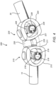
- FIG. 4 is a schematic illustration of a further embodiment of the double cardan joint 200 of the present invention.
- the resilient member 235 includes an elastic component, such as a flexible rubber component, spanning between the input arc guard 211 of the input yoke 210 and the output arc guard 221 of the output yoke 220.
- the resilient member 235 includes multiple resilient components. In further embodiments, the resilient member 235 includes a combination of resilient and rigid components.
Landscapes
- Engineering & Computer Science (AREA)
- General Engineering & Computer Science (AREA)
- Mechanical Engineering (AREA)
- Steering Controls (AREA)
- Vibration Prevention Devices (AREA)
Claims (8)
- Doppelkardangelenkanordnung (200), umfassend:eine Eingangsgabel (210);einen Eingangsquerträger (215), der mit der Eingangsgabel (210) gekoppelt ist;eine Ausgangsgabel (220);einen Ausgangsquerträger (225), der mit der Ausgangsgabel (220) gekoppelt ist; undeine Mittelgabel (230), die mit dem Eingangsquerträger (215) gekoppelt ist, wodurch ein Eingangskreuzgelenk mit der Eingangsgabel (210) und dem Eingangsquerträger (215) gebildet wird, und mit dem Ausgangsquerträger (225) gekoppelt ist, wodurch ein Ausgangskreuzgelenk mit der Ausgangsgabel (220) und dem Ausgangsquerträger (225) gebildet wird; gekennzeichnet durchein federndes Element (235), das zwischen dem Eingangskreuzgelenk und dem Ausgangskreuzgelenk positioniert ist, wobei das federnde Element (235) dazu ausgelegt ist, die Doppelkardangelenkanordnung (200) zu zentrieren und auszurichten, wobei sich das federnde Element (235) zwischen einem Eingangslichtbogenschutz (211) der Eingangsgabel (210) und einem Ausgangslichtbogenschutz (221) der Ausgangsgabel (220) erstreckt.
- Doppelkardangelenkanordnung (200) nach Anspruch 1, wobei das federnde Element (235) eine lineare Feder und/oder eine Schraubenfeder und/oder eine Wellenfeder umfasst.
- Doppelkardangelenkanordnung (200) nach Anspruch 1, wobei das federnde Element (235) eine elastische Komponente umfasst.
- Doppelkardangelenkanordnung (200) nach Anspruch 1, wobei das federnde Element (235) eine Kombination aus elastischen und starren Komponenten umfasst.
- Verfahren zum Herstellen einer Doppelkardangelenkanordnung (200), wobei das Verfahren Folgendes umfasst:Bereitstellen einer Eingangsgabel (210);Bereitstellen eines Eingangsquerträgers (215), der mit der Eingangsgabel (210) gekoppelt ist;Bereitstellen einer Ausgangsgabel (220);Bereitstellen eines Ausgangsquerträgers (225), der mit der Ausgangsgabel (220) gekoppelt ist;Koppeln einer Mittelgabel (230) mit dem Eingangsquerträger (215), wodurch ein Eingangskreuzgelenk mit der Eingangsgabel (210) und dem Eingangsquerträger (215) gebildet wird; undKoppeln der Mittelgabel (230) mit dem Ausgangsquerträger (225), wodurch ein Ausgangskreuzgelenk mit der Ausgangsgabel (220) und dem Ausgangsquerträger (225) gebildet wird;gekennzeichnet durch Positionieren eines federnden Elements (235) zwischen dem Eingangskreuzgelenk und dem Ausgangskreuzgelenk, wobei das federnde Element (235) dazu ausgelegt ist, die Doppelkardangelenkanordnung (200) zu zentrieren und auszurichten, wobei sich das federnde Element (235) zwischen einem Eingangslichtbogenschutz (211) der Eingangsgabel (210) und einem Ausgangslichtbogenschutz (221) der Ausgangsgabel (220) erstreckt.
- Verfahren nach Anspruch 5, wobei das federnde Element (235) eine lineare Feder und/oder eine Schraubenfeder und/oder eine Wellenfeder umfasst.
- Verfahren nach Anspruch 5, wobei das federnde Element (235) eine elastische Komponente umfasst.
- Verfahren nach Anspruch 5, wobei das federnde Element (235) eine Kombination aus elastischen und starren Komponenten umfasst.
Applications Claiming Priority (2)
| Application Number | Priority Date | Filing Date | Title |
|---|---|---|---|
| US202163150611P | 2021-02-18 | 2021-02-18 | |
| US17/665,843 US20220260120A1 (en) | 2021-02-18 | 2022-02-07 | Spring guided double cardan joint |
Publications (2)
| Publication Number | Publication Date |
|---|---|
| EP4047232A1 EP4047232A1 (de) | 2022-08-24 |
| EP4047232B1 true EP4047232B1 (de) | 2025-06-18 |
Family
ID=80446416
Family Applications (1)
| Application Number | Title | Priority Date | Filing Date |
|---|---|---|---|
| EP22156173.1A Active EP4047232B1 (de) | 2021-02-18 | 2022-02-10 | Federgeführtes doppel-kardangelenk |
Country Status (3)
| Country | Link |
|---|---|
| US (1) | US20220260120A1 (de) |
| EP (1) | EP4047232B1 (de) |
| CN (1) | CN114962475B (de) |
Citations (2)
| Publication number | Priority date | Publication date | Assignee | Title |
|---|---|---|---|---|
| US4075871A (en) * | 1976-02-27 | 1978-02-28 | General Motors Corporation | Double Cardan joint with elastomeric centering means |
| JPS63120919A (ja) * | 1986-11-07 | 1988-05-25 | Honda Motor Co Ltd | 等速自在継手 |
Family Cites Families (17)
| Publication number | Priority date | Publication date | Assignee | Title |
|---|---|---|---|---|
| FR846797A (fr) * | 1938-05-30 | 1939-09-26 | Const Mecaniques Chenard & Wal | Joint universel |
| US2137179A (en) * | 1938-07-09 | 1938-11-15 | Frank E Nelson | Spring toggle universal joint |
| US3429144A (en) * | 1967-08-17 | 1969-02-25 | Borg Warner | Center bearing double cardan joint |
| US4395246A (en) * | 1980-09-05 | 1983-07-26 | The Bendix Corporation | Universal joint |
| IT1160178B (it) * | 1983-01-14 | 1987-03-04 | Pirelli | Giunto di trasmissione |
| US4540383A (en) * | 1984-03-15 | 1985-09-10 | Allied Corporation | Centering device for a constant velocity joint |
| CN85202685U (zh) * | 1985-07-04 | 1986-04-23 | 雷良榆 | 高功率减振大挠度扭转弹簧式联轴器 |
| CN2055879U (zh) * | 1989-09-19 | 1990-04-11 | 宋文俊 | 具有锁定装置的双球体万向节 |
| DE4141325A1 (de) * | 1991-12-14 | 1993-06-17 | Nicolae Dr Ing Souca | Homokinetisches doppelkardangelenk elastisch zentriert |
| JP3590482B2 (ja) * | 1996-07-26 | 2004-11-17 | 光洋機械工業株式会社 | 等速ユニバーサルジョイント |
| AU2003256445A1 (en) * | 2002-08-28 | 2004-03-19 | Kwok-Wah Pun | Constant velocity universal joint with less axles and can bend a greater angle |
| US7361093B2 (en) * | 2005-05-10 | 2008-04-22 | Arvinmeritor Technology, Llc | Universal joint with cup retainer |
| CN200982361Y (zh) * | 2006-12-14 | 2007-11-28 | 上海宝钢设备检修有限公司 | 一种测速机弹簧式联轴器结构 |
| CN201763842U (zh) * | 2010-07-23 | 2011-03-16 | 陈金辉 | 一种万向接头 |
| CN204716795U (zh) * | 2015-06-19 | 2015-10-21 | 钟奕丁 | 一种大摆角汽车用双速万向节轴总成 |
| DE102017003248A1 (de) * | 2017-04-04 | 2018-10-04 | Cae Consulting & Engineering Gmbh | Drehspielfreies und schwingungsreduzierendes Wellengelenk bzw. Kardangelenk |
| CN116857294B (zh) * | 2022-03-28 | 2026-07-17 | 操纵技术Ip控股公司 | 双万向节等速可调节接头 |
-
2022
- 2022-02-07 US US17/665,843 patent/US20220260120A1/en not_active Abandoned
- 2022-02-10 EP EP22156173.1A patent/EP4047232B1/de active Active
- 2022-02-18 CN CN202210149213.5A patent/CN114962475B/zh active Active
Patent Citations (2)
| Publication number | Priority date | Publication date | Assignee | Title |
|---|---|---|---|---|
| US4075871A (en) * | 1976-02-27 | 1978-02-28 | General Motors Corporation | Double Cardan joint with elastomeric centering means |
| JPS63120919A (ja) * | 1986-11-07 | 1988-05-25 | Honda Motor Co Ltd | 等速自在継手 |
Also Published As
| Publication number | Publication date |
|---|---|
| CN114962475A (zh) | 2022-08-30 |
| US20220260120A1 (en) | 2022-08-18 |
| CN114962475B (zh) | 2023-12-12 |
| EP4047232A1 (de) | 2022-08-24 |
Similar Documents
| Publication | Publication Date | Title |
|---|---|---|
| US5931597A (en) | Ball joint | |
| EP0725904B1 (de) | Lenksäule | |
| JP4616474B2 (ja) | 2軸のトルク伝達の連結のためのねじり剛性を有し遊びがない金属製ベローズ型可撓性カップリング | |
| JPH06137317A (ja) | 旋回支承装置 | |
| JPS61211529A (ja) | 機械的動力伝達継手を密封するブーツ | |
| US3965700A (en) | Drive line coupling device with substantially homokinetic features | |
| US6948857B2 (en) | Bearing system | |
| KR101120658B1 (ko) | 유니버셜 조인트 | |
| EP4047232A1 (de) | Federgeführtes doppel-kardangelenk | |
| JPH0254444B2 (de) | ||
| US6146280A (en) | Spring biased universal joint | |
| EP1783387A1 (de) | Universelles verbindungsstück | |
| JP5834968B2 (ja) | 十字軸式自在継手 | |
| US7476156B2 (en) | Homokinetic joint | |
| JP4889875B2 (ja) | プロペラシャフト | |
| JP2009115203A (ja) | 等速自在継手 | |
| US12135063B2 (en) | Lockable axis slim type universal joint | |
| JP2003287053A (ja) | ステアリング装置用自在継手 | |
| JP2024123579A (ja) | シール構造と、このシール構造を備えた等速自在継手と、この等速自在継手を備えた動力伝達装置 | |
| JP5983812B2 (ja) | 十字軸式自在継手 | |
| JP2019124319A (ja) | 等速自在継手 | |
| JPH09324823A (ja) | ダブルカルダン式等速ジョイント | |
| CN111791224A (zh) | 传动组件、关节机构及机器人 | |
| KR20210087668A (ko) | 유니버셜 조인트 | |
| JPH03168417A (ja) | たわみ軸継手 |
Legal Events
| Date | Code | Title | Description |
|---|---|---|---|
| PUAI | Public reference made under article 153(3) epc to a published international application that has entered the european phase |
Free format text: ORIGINAL CODE: 0009012 |
|
| STAA | Information on the status of an ep patent application or granted ep patent |
Free format text: STATUS: THE APPLICATION HAS BEEN PUBLISHED |
|
| AK | Designated contracting states |
Kind code of ref document: A1 Designated state(s): AL AT BE BG CH CY CZ DE DK EE ES FI FR GB GR HR HU IE IS IT LI LT LU LV MC MK MT NL NO PL PT RO RS SE SI SK SM TR |
|
| STAA | Information on the status of an ep patent application or granted ep patent |
Free format text: STATUS: REQUEST FOR EXAMINATION WAS MADE |
|
| 17P | Request for examination filed |
Effective date: 20230224 |
|
| RBV | Designated contracting states (corrected) |
Designated state(s): AL AT BE BG CH CY CZ DE DK EE ES FI FR GB GR HR HU IE IS IT LI LT LU LV MC MK MT NL NO PL PT RO RS SE SI SK SM TR |
|
| P01 | Opt-out of the competence of the unified patent court (upc) registered |
Effective date: 20230828 |
|
| STAA | Information on the status of an ep patent application or granted ep patent |
Free format text: STATUS: EXAMINATION IS IN PROGRESS |
|
| 17Q | First examination report despatched |
Effective date: 20231019 |
|
| GRAP | Despatch of communication of intention to grant a patent |
Free format text: ORIGINAL CODE: EPIDOSNIGR1 |
|
| STAA | Information on the status of an ep patent application or granted ep patent |
Free format text: STATUS: GRANT OF PATENT IS INTENDED |
|
| INTG | Intention to grant announced |
Effective date: 20241210 |
|
| GRAS | Grant fee paid |
Free format text: ORIGINAL CODE: EPIDOSNIGR3 |
|
| GRAA | (expected) grant |
Free format text: ORIGINAL CODE: 0009210 |
|
| STAA | Information on the status of an ep patent application or granted ep patent |
Free format text: STATUS: THE PATENT HAS BEEN GRANTED |
|
| AK | Designated contracting states |
Kind code of ref document: B1 Designated state(s): AL AT BE BG CH CY CZ DE DK EE ES FI FR GB GR HR HU IE IS IT LI LT LU LV MC MK MT NL NO PL PT RO RS SE SI SK SM TR |
|
| REG | Reference to a national code |
Ref country code: GB Ref legal event code: FG4D |
|
| REG | Reference to a national code |
Ref country code: CH Ref legal event code: EP |
|
| REG | Reference to a national code |
Ref country code: DE Ref legal event code: R096 Ref document number: 602022015959 Country of ref document: DE |
|
| REG | Reference to a national code |
Ref country code: CH Ref legal event code: EP |
|
| REG | Reference to a national code |
Ref country code: IE Ref legal event code: FG4D |
|
| PG25 | Lapsed in a contracting state [announced via postgrant information from national office to epo] |
Ref country code: FI Free format text: LAPSE BECAUSE OF FAILURE TO SUBMIT A TRANSLATION OF THE DESCRIPTION OR TO PAY THE FEE WITHIN THE PRESCRIBED TIME-LIMIT Effective date: 20250618 |
|
| REG | Reference to a national code |
Ref country code: LT Ref legal event code: MG9D |
|
| PG25 | Lapsed in a contracting state [announced via postgrant information from national office to epo] |
Ref country code: NO Free format text: LAPSE BECAUSE OF FAILURE TO SUBMIT A TRANSLATION OF THE DESCRIPTION OR TO PAY THE FEE WITHIN THE PRESCRIBED TIME-LIMIT Effective date: 20250918 Ref country code: GR Free format text: LAPSE BECAUSE OF FAILURE TO SUBMIT A TRANSLATION OF THE DESCRIPTION OR TO PAY THE FEE WITHIN THE PRESCRIBED TIME-LIMIT Effective date: 20250919 |
|
| PG25 | Lapsed in a contracting state [announced via postgrant information from national office to epo] |
Ref country code: BG Free format text: LAPSE BECAUSE OF FAILURE TO SUBMIT A TRANSLATION OF THE DESCRIPTION OR TO PAY THE FEE WITHIN THE PRESCRIBED TIME-LIMIT Effective date: 20250618 |
|
| PG25 | Lapsed in a contracting state [announced via postgrant information from national office to epo] |
Ref country code: HR Free format text: LAPSE BECAUSE OF FAILURE TO SUBMIT A TRANSLATION OF THE DESCRIPTION OR TO PAY THE FEE WITHIN THE PRESCRIBED TIME-LIMIT Effective date: 20250618 |
|
| PG25 | Lapsed in a contracting state [announced via postgrant information from national office to epo] |
Ref country code: RS Free format text: LAPSE BECAUSE OF FAILURE TO SUBMIT A TRANSLATION OF THE DESCRIPTION OR TO PAY THE FEE WITHIN THE PRESCRIBED TIME-LIMIT Effective date: 20250918 |
|
| REG | Reference to a national code |
Ref country code: NL Ref legal event code: MP Effective date: 20250618 |
|
| PG25 | Lapsed in a contracting state [announced via postgrant information from national office to epo] |
Ref country code: LV Free format text: LAPSE BECAUSE OF FAILURE TO SUBMIT A TRANSLATION OF THE DESCRIPTION OR TO PAY THE FEE WITHIN THE PRESCRIBED TIME-LIMIT Effective date: 20250618 |
|
| PG25 | Lapsed in a contracting state [announced via postgrant information from national office to epo] |
Ref country code: NL Free format text: LAPSE BECAUSE OF FAILURE TO SUBMIT A TRANSLATION OF THE DESCRIPTION OR TO PAY THE FEE WITHIN THE PRESCRIBED TIME-LIMIT Effective date: 20250618 |
|
| PG25 | Lapsed in a contracting state [announced via postgrant information from national office to epo] |
Ref country code: PT Free format text: LAPSE BECAUSE OF FAILURE TO SUBMIT A TRANSLATION OF THE DESCRIPTION OR TO PAY THE FEE WITHIN THE PRESCRIBED TIME-LIMIT Effective date: 20251020 |
|
| REG | Reference to a national code |
Ref country code: AT Ref legal event code: MK05 Ref document number: 1804416 Country of ref document: AT Kind code of ref document: T Effective date: 20250618 |
|
| PG25 | Lapsed in a contracting state [announced via postgrant information from national office to epo] |
Ref country code: IS Free format text: LAPSE BECAUSE OF FAILURE TO SUBMIT A TRANSLATION OF THE DESCRIPTION OR TO PAY THE FEE WITHIN THE PRESCRIBED TIME-LIMIT Effective date: 20251018 |
|
| PG25 | Lapsed in a contracting state [announced via postgrant information from national office to epo] |
Ref country code: AT Free format text: LAPSE BECAUSE OF FAILURE TO SUBMIT A TRANSLATION OF THE DESCRIPTION OR TO PAY THE FEE WITHIN THE PRESCRIBED TIME-LIMIT Effective date: 20250618 Ref country code: SM Free format text: LAPSE BECAUSE OF FAILURE TO SUBMIT A TRANSLATION OF THE DESCRIPTION OR TO PAY THE FEE WITHIN THE PRESCRIBED TIME-LIMIT Effective date: 20250618 |
|
| PG25 | Lapsed in a contracting state [announced via postgrant information from national office to epo] |
Ref country code: CZ Free format text: LAPSE BECAUSE OF FAILURE TO SUBMIT A TRANSLATION OF THE DESCRIPTION OR TO PAY THE FEE WITHIN THE PRESCRIBED TIME-LIMIT Effective date: 20250618 |
|
| PG25 | Lapsed in a contracting state [announced via postgrant information from national office to epo] |
Ref country code: PL Free format text: LAPSE BECAUSE OF FAILURE TO SUBMIT A TRANSLATION OF THE DESCRIPTION OR TO PAY THE FEE WITHIN THE PRESCRIBED TIME-LIMIT Effective date: 20250618 |
|
| PG25 | Lapsed in a contracting state [announced via postgrant information from national office to epo] |
Ref country code: EE Free format text: LAPSE BECAUSE OF FAILURE TO SUBMIT A TRANSLATION OF THE DESCRIPTION OR TO PAY THE FEE WITHIN THE PRESCRIBED TIME-LIMIT Effective date: 20250618 |
|
| PG25 | Lapsed in a contracting state [announced via postgrant information from national office to epo] |
Ref country code: SK Free format text: LAPSE BECAUSE OF FAILURE TO SUBMIT A TRANSLATION OF THE DESCRIPTION OR TO PAY THE FEE WITHIN THE PRESCRIBED TIME-LIMIT Effective date: 20250618 |
|
| PG25 | Lapsed in a contracting state [announced via postgrant information from national office to epo] |
Ref country code: ES Free format text: LAPSE BECAUSE OF FAILURE TO SUBMIT A TRANSLATION OF THE DESCRIPTION OR TO PAY THE FEE WITHIN THE PRESCRIBED TIME-LIMIT Effective date: 20250618 |
|
| REG | Reference to a national code |
Ref country code: DE Ref legal event code: R097 Ref document number: 602022015959 Country of ref document: DE |
|
| PGFP | Annual fee paid to national office [announced via postgrant information from national office to epo] |
Ref country code: GB Payment date: 20260122 Year of fee payment: 5 |
|
| PG25 | Lapsed in a contracting state [announced via postgrant information from national office to epo] |
Ref country code: DK Free format text: LAPSE BECAUSE OF FAILURE TO SUBMIT A TRANSLATION OF THE DESCRIPTION OR TO PAY THE FEE WITHIN THE PRESCRIBED TIME-LIMIT Effective date: 20250618 |
|
| PGFP | Annual fee paid to national office [announced via postgrant information from national office to epo] |
Ref country code: DE Payment date: 20260121 Year of fee payment: 5 |
|
| PG25 | Lapsed in a contracting state [announced via postgrant information from national office to epo] |
Ref country code: IT Free format text: LAPSE BECAUSE OF FAILURE TO SUBMIT A TRANSLATION OF THE DESCRIPTION OR TO PAY THE FEE WITHIN THE PRESCRIBED TIME-LIMIT Effective date: 20250618 |
|
| PGFP | Annual fee paid to national office [announced via postgrant information from national office to epo] |
Ref country code: FR Payment date: 20260121 Year of fee payment: 5 |
|
| PLBE | No opposition filed within time limit |
Free format text: ORIGINAL CODE: 0009261 |
|
| STAA | Information on the status of an ep patent application or granted ep patent |
Free format text: STATUS: NO OPPOSITION FILED WITHIN TIME LIMIT |
|
| REG | Reference to a national code |
Ref country code: CH Ref legal event code: L10 Free format text: ST27 STATUS EVENT CODE: U-0-0-L10-L00 (AS PROVIDED BY THE NATIONAL OFFICE) Effective date: 20260430 |
|
| 26N | No opposition filed |
Effective date: 20260319 |
|
| PG25 | Lapsed in a contracting state [announced via postgrant information from national office to epo] |
Ref country code: LT Free format text: LAPSE BECAUSE OF FAILURE TO SUBMIT A TRANSLATION OF THE DESCRIPTION OR TO PAY THE FEE WITHIN THE PRESCRIBED TIME-LIMIT Effective date: 20250618 |
|
| PG25 | Lapsed in a contracting state [announced via postgrant information from national office to epo] |
Ref country code: SE Free format text: LAPSE BECAUSE OF FAILURE TO SUBMIT A TRANSLATION OF THE DESCRIPTION OR TO PAY THE FEE WITHIN THE PRESCRIBED TIME-LIMIT Effective date: 20250618 |