EP4046840A1 - Véhicule électrique - Google Patents
Véhicule électrique Download PDFInfo
- Publication number
- EP4046840A1 EP4046840A1 EP22157082.3A EP22157082A EP4046840A1 EP 4046840 A1 EP4046840 A1 EP 4046840A1 EP 22157082 A EP22157082 A EP 22157082A EP 4046840 A1 EP4046840 A1 EP 4046840A1
- Authority
- EP
- European Patent Office
- Prior art keywords
- plate member
- battery
- electrical component
- electric vehicle
- seat
- Prior art date
- Legal status (The legal status is an assumption and is not a legal conclusion. Google has not performed a legal analysis and makes no representation as to the accuracy of the status listed.)
- Granted
Links
Images


Classifications
-
- A—HUMAN NECESSITIES
- A01—AGRICULTURE; FORESTRY; ANIMAL HUSBANDRY; HUNTING; TRAPPING; FISHING
- A01D—HARVESTING; MOWING
- A01D34/00—Mowers; Mowing apparatus of harvesters
- A01D34/01—Mowers; Mowing apparatus of harvesters characterised by features relating to the type of cutting apparatus
- A01D34/412—Mowers; Mowing apparatus of harvesters characterised by features relating to the type of cutting apparatus having rotating cutters
- A01D34/63—Mowers; Mowing apparatus of harvesters characterised by features relating to the type of cutting apparatus having rotating cutters having cutters rotating about a vertical axis
- A01D34/64—Mowers; Mowing apparatus of harvesters characterised by features relating to the type of cutting apparatus having rotating cutters having cutters rotating about a vertical axis mounted on a vehicle, e.g. a tractor, or drawn by an animal or a vehicle
-
- A—HUMAN NECESSITIES
- A01—AGRICULTURE; FORESTRY; ANIMAL HUSBANDRY; HUNTING; TRAPPING; FISHING
- A01D—HARVESTING; MOWING
- A01D34/00—Mowers; Mowing apparatus of harvesters
- A01D34/01—Mowers; Mowing apparatus of harvesters characterised by features relating to the type of cutting apparatus
- A01D34/412—Mowers; Mowing apparatus of harvesters characterised by features relating to the type of cutting apparatus having rotating cutters
- A01D34/63—Mowers; Mowing apparatus of harvesters characterised by features relating to the type of cutting apparatus having rotating cutters having cutters rotating about a vertical axis
- A01D34/76—Driving mechanisms for the cutters
- A01D34/78—Driving mechanisms for the cutters electric
-
- B—PERFORMING OPERATIONS; TRANSPORTING
- B60—VEHICLES IN GENERAL
- B60K—ARRANGEMENT OR MOUNTING OF PROPULSION UNITS OR OF TRANSMISSIONS IN VEHICLES; ARRANGEMENT OR MOUNTING OF PLURAL DIVERSE PRIME-MOVERS IN VEHICLES; AUXILIARY DRIVES FOR VEHICLES; INSTRUMENTATION OR DASHBOARDS FOR VEHICLES; ARRANGEMENTS IN CONNECTION WITH COOLING, AIR INTAKE, GAS EXHAUST OR FUEL SUPPLY OF PROPULSION UNITS IN VEHICLES
- B60K1/00—Arrangement or mounting of electrical propulsion units
- B60K1/04—Arrangement or mounting of electrical propulsion units of the electric storage means for propulsion
-
- A—HUMAN NECESSITIES
- A01—AGRICULTURE; FORESTRY; ANIMAL HUSBANDRY; HUNTING; TRAPPING; FISHING
- A01D—HARVESTING; MOWING
- A01D2101/00—Lawn-mowers
-
- B—PERFORMING OPERATIONS; TRANSPORTING
- B60—VEHICLES IN GENERAL
- B60K—ARRANGEMENT OR MOUNTING OF PROPULSION UNITS OR OF TRANSMISSIONS IN VEHICLES; ARRANGEMENT OR MOUNTING OF PLURAL DIVERSE PRIME-MOVERS IN VEHICLES; AUXILIARY DRIVES FOR VEHICLES; INSTRUMENTATION OR DASHBOARDS FOR VEHICLES; ARRANGEMENTS IN CONNECTION WITH COOLING, AIR INTAKE, GAS EXHAUST OR FUEL SUPPLY OF PROPULSION UNITS IN VEHICLES
- B60K1/00—Arrangement or mounting of electrical propulsion units
- B60K1/04—Arrangement or mounting of electrical propulsion units of the electric storage means for propulsion
- B60K2001/0405—Arrangement or mounting of electrical propulsion units of the electric storage means for propulsion characterised by their position
- B60K2001/0411—Arrangement in the front part of the vehicle
-
- B—PERFORMING OPERATIONS; TRANSPORTING
- B60—VEHICLES IN GENERAL
- B60K—ARRANGEMENT OR MOUNTING OF PROPULSION UNITS OR OF TRANSMISSIONS IN VEHICLES; ARRANGEMENT OR MOUNTING OF PLURAL DIVERSE PRIME-MOVERS IN VEHICLES; AUXILIARY DRIVES FOR VEHICLES; INSTRUMENTATION OR DASHBOARDS FOR VEHICLES; ARRANGEMENTS IN CONNECTION WITH COOLING, AIR INTAKE, GAS EXHAUST OR FUEL SUPPLY OF PROPULSION UNITS IN VEHICLES
- B60K1/00—Arrangement or mounting of electrical propulsion units
- B60K1/04—Arrangement or mounting of electrical propulsion units of the electric storage means for propulsion
- B60K2001/0405—Arrangement or mounting of electrical propulsion units of the electric storage means for propulsion characterised by their position
- B60K2001/0416—Arrangement in the rear part of the vehicle
-
- B—PERFORMING OPERATIONS; TRANSPORTING
- B60—VEHICLES IN GENERAL
- B60K—ARRANGEMENT OR MOUNTING OF PROPULSION UNITS OR OF TRANSMISSIONS IN VEHICLES; ARRANGEMENT OR MOUNTING OF PLURAL DIVERSE PRIME-MOVERS IN VEHICLES; AUXILIARY DRIVES FOR VEHICLES; INSTRUMENTATION OR DASHBOARDS FOR VEHICLES; ARRANGEMENTS IN CONNECTION WITH COOLING, AIR INTAKE, GAS EXHAUST OR FUEL SUPPLY OF PROPULSION UNITS IN VEHICLES
- B60K1/00—Arrangement or mounting of electrical propulsion units
- B60K1/04—Arrangement or mounting of electrical propulsion units of the electric storage means for propulsion
- B60K2001/0405—Arrangement or mounting of electrical propulsion units of the electric storage means for propulsion characterised by their position
- B60K2001/0422—Arrangement under the front seats
-
- B—PERFORMING OPERATIONS; TRANSPORTING
- B60—VEHICLES IN GENERAL
- B60K—ARRANGEMENT OR MOUNTING OF PROPULSION UNITS OR OF TRANSMISSIONS IN VEHICLES; ARRANGEMENT OR MOUNTING OF PLURAL DIVERSE PRIME-MOVERS IN VEHICLES; AUXILIARY DRIVES FOR VEHICLES; INSTRUMENTATION OR DASHBOARDS FOR VEHICLES; ARRANGEMENTS IN CONNECTION WITH COOLING, AIR INTAKE, GAS EXHAUST OR FUEL SUPPLY OF PROPULSION UNITS IN VEHICLES
- B60K1/00—Arrangement or mounting of electrical propulsion units
- B60K1/04—Arrangement or mounting of electrical propulsion units of the electric storage means for propulsion
- B60K2001/0455—Removal or replacement of the energy storages
- B60K2001/0494—Removal or replacement of the energy storages with arrangements for sliding
-
- B—PERFORMING OPERATIONS; TRANSPORTING
- B60—VEHICLES IN GENERAL
- B60Y—INDEXING SCHEME RELATING TO ASPECTS CROSS-CUTTING VEHICLE TECHNOLOGY
- B60Y2200/00—Type of vehicle
- B60Y2200/20—Off-Road Vehicles
- B60Y2200/22—Agricultural vehicles
- B60Y2200/223—Ridable lawn mowers
Definitions
- the present disclosure relates to an electric vehicle.
- JP 2018-184035 A discloses a lawn mowing vehicle (electric vehicle) in which left and right wheels can be driven by left and right electric motors, respectively.
- the vehicle has a storage box which is attachable to and detachable from a vehicle body by bolts.
- the storage box contains electrical components such as inverters, converters, main relays, and various types of fuses.
- JP 2018-184035 A discloses that electrical components such as inverters and the like are accommodated in a storage box that is attachable to and detachable from the vehicle body under the seat. Although this may protect the electrical components from splashing rainwater, when performing repairs or maintenance, it is necessary to remove a heavy storage box from the vehicle body after the seat is separated therefrom, and thus there is a need to improve workability.
- An object of the present disclosure is to provide an electric vehicle capable of protecting inverters and electrical components from splashing rainwater, improving the appearance of the electric vehicle when in use, and improving the workability of repairs and maintenance.
- an electric vehicle which includes: a body frame; a seat disposed on the body frame; a wheel attached to the body frame to be driven by an electric motor; a battery to supply electric power to the electric motor via an inverter and an electrical component; a plate member placed inside a covered space with a top being covered and on which the inverter and the electrical component are mounted; and a guide supported by the body frame to drawably guide the plate member from a position inside the covered space to a position outside the covered space.
- an electric vehicle is described as a lawn mowing vehicle, but the electric vehicle of the present disclosure is not limited thereto, and may be a work vehicle equipped with a work machine capable of performing at least one task, such as snow removal, excavation, civil engineering, or agricultural work, or an off-road type utility vehicle having a cargo bed and traveling on uneven terrain, or an all-terrain vehicle (ATV) called a buggy, or a Recreational Vehicle (RV), or a Recreational Off-highway Vehicle (ROV).
- ATV all-terrain vehicle
- RV Recreational Vehicle
- ROV Recreational Off-highway Vehicle
- the electric vehicle in which two rear wheels are driven with two motors, respectively, is described as an example, but it may be configured so that the two rear wheels are driven with a single motor.
- the electric vehicle may also be configured so that two front wheels are driven with a single motor or twin motors.
- a left-right lever-type operator with left and right operation levers is described as only an example, but the present disclosure is not limited thereto; a steering handle may be used as a steering controller, and an accelerator pedal provided in front of a seat may be used as an acceleration controller.
- the same elements are denoted by identical reference numerals throughout all the drawings.
- FIGS. 1A through 10 show a first embodiment.
- FIG. 1A is a perspective view of an electric vehicle 10 according to the embodiment.
- FIG. 1B is a partially enlarged diagram illustrating an area A of FIG. 1A .
- FIG. 2 is a side view of the electric vehicle 10 shown in FIG. 1A in which a portion of the electric vehicle is illustrated as a cross sectional view.
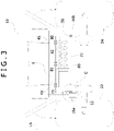
- FIG. 3 is a cross sectional view taken along line B-B of FIG. 2
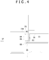
- FIG. 4 is a partially enlarged diagram illustrating an area C of FIG. 3 .
- a side indicated by Fr is defined as the front side
- a side indicated by Lh is defined as the left side.
- the electric vehicle 10 is of the riding type that a driver sitting in a seat 17 can drive, and includes a body frame 16, two caster wheels 18, 20 of left and right front wheels, two wheels 22, 24 of left and right rear wheels (see FIG. 3 ), a lawn mower 25 of a work machine, and two operation levers 34, 36 of right-and left levers.
- the body frame 16 is formed by coupling a plurality of lateral frames 16c extending in a lateral direction to two main frames 16a and 16b extending in a front-and-rear direction on the right and left sides.
- FIGS. 1 and 6 only one of the plurality of lateral frames 16c, which is provided at the front end of the vehicle, is shown.
- the seat 17 is positioned and fixed on the upper side of the middle portion in the front-and-rear direction of the body frame 16.
- the left and right caster wheels 18, 20 are supported on the front side from a front end of the body frame 16. As each of caster wheels 18, 20 is rotatable freely more than 360 degrees around a vertical axis.
- the left and right wheels 22, 24 are rotatably attached on the rear side of the body frame 16.
- the left and right wheels 22, 24 are main drive wheels and are driven by left and right electric motors 70 for traveling, respectively (see FIG. 2 ).
- a plurality of batteries 41 supply electric power to the electric motors 70 through electrical components 71 and inverters 72 (see FIG. 8 ).
- the electrical component 71 includes a plurality of contactors, bus bars and fuses. In this disclosure, it is assumed that the inverter 72 is a component different from the electrical components 71.
- the plurality of batteries 41 are electrically connected to each other in parallel or in series.
- one side electrode of the plurality of batteries 41 is connected to the first bus bar via a fuse, and the first bus bar is connected to the second bus bar via a plurality of contactors.
- the second bus bar is connected to a plurality of electric motors 70 including the left and right electric motors 70 via a plurality of the inverters 72.
- the plurality of batteries 41 are fixed on the upper side of the body frame 16 and on the rear side of the seat 17 of the electric vehicle 10 and are covered by a battery cover 42.
- the number of the plurality of batteries 41 is three, with two batteries 41 being disposed on the upper side and one battery 41 being disposed on the lower side.
- a partition (not shown) is provided between the upper side and lower side batteries 41 inside the battery cover 42.
- the two upper side batteries 41 are arranged side by side so that the longitudinal direction of each battery is aligned with the right-and-left direction.
- the one lower side battery 41 is positioned at the center in the right-and-left direction of the battery cover 42 so that a longitudinal direction of the battery is aligned with the front-and-rear direction.
- the inverters 72 convert DC power supplied from the batteries 41 into AC power and output it to the electric motors 70. Only one battery 41 may supply electric power to the electric motors 70 through the electrical components 71 and the inverters 72.
- only one caster wheel or three or more caster wheels may be attached to the electric vehicle 10, for example.
- the caster wheels and the wheels of the driving wheels may be replaced in the front-and-rear direction.
- the lawn mower 25 is supported under the body frame 16 at the middle of the body frame 16 in the front and rear direction.
- the lawn mower 25 includes a mower deck 26 and three lawn mower blades (not shown) as a mowing rotary tool, each of which is rotatable around a vertical axis inside the mower deck 26.
- the rotation of the lawn mower blades makes it possible to break up and mow grass, etc.
- Each of the lawn mower blades is driven by an electric motor for the mower (not shown).
- the rotation of the lawn mower blade makes it possible to mow the lawn, and the mowed grass is discharged from the inside of the mower deck 26 to the outside in the left- and right direction.
- the lawn mower may be configured to comprise a lawn mowing reel as a rotary tool for mowing the lawn, which has a spiral blade, for example, arranged on a cylinder with a rotation axis parallel to a ground surface, functions to pinch and mow the grass or the like, and is driven by a deck motor.
- a lawn mowing reel as a rotary tool for mowing the lawn, which has a spiral blade, for example, arranged on a cylinder with a rotation axis parallel to a ground surface, functions to pinch and mow the grass or the like, and is driven by a deck motor.
- the left and right operation levers 34 and 36 are provided on respective sides of the seat 17 to be able to pivot around a horizontal axis which is aligned with the right-and-left direction and swing toward the front-and-rear direction.
- the electric motor 70 for traveling stops rotating.
- instructions are issued such that a direction and speed of rotation of the electric motor 70 on the corresponding side are to be changed according to a direction and amount of swinging.
- the swinging position of the operation levers 34, 36 in the front-and-rear direction is detected with a lever sensor (not shown).
- the detection signal of the lever sensor is input to the control unit (not shown) installed in the vehicle as a signal indicating a rotation instruction of the electric motor 70, and the control unit rotates the electric motor 70 in a direction following the instruction.
- the driving power of each of the electric motors 70 is transmitted to the left and right wheels 22, 24 through gears and the like. This allows the vehicle to travel in the front-and-rear direction depending on the operation of the operation levers 34, 36.
- a difference in a rotation speed between the left and right wheels 22, 24 is caused by varying an amount of a swinging operation between the left and right operation levers 34, 36, so that the vehicle can turn. Furthermore, by tilting one of the two operation levers 34, 36 to the front side and the other to the rear side, the left and right wheels 22, 24 rotate in opposite directions, so that the turning radius decreases to cause the vehicle to turn quickly.
- the inverters 72 and the electrical components 71 are mounted on a plate member 50 (see FIG. 2 ), and the plate member 50 is positioned in a covered space S (see FIG. 2 ) which is under the seat 17 with the top being covered.
- the electric vehicle 10 is provided with a configuration in which the plate member 50 is drawably guided from a position inside the covered space S to a position outside the covered space S by a guide 75 (see FIG. 3 ) supported by the body frame 16.
- the electric vehicle 10 has a seat frame 45 to fix the seat 17 to the body frame 16 so as to bridge over the left and right main frames 16a, 16b along the front-and-rear direction.
- the seat frame 45 has a vertically extending inverted U-shaped front end plate 46 with an opening 46a on the inside and a U-shaped top plate 47 horizontally extending to the rear side, and an upper end of the front end plate 46 is coupled to a front end of the top plate 47.
- the top plate 47 is fixed to the body frame 16 either directly or via a support base 48 described below, which is provided under the seat 17.
- the seat 17 is fixed on the top plate 47 so as to block a U-shaped inner opening of the top plate.
- the U-shaped inner opening of the top plate 47 is not necessarily provided.
- the covered space S with the top being covered is formed under the seat 17.
- the front end plate 46 is provided with a lid 49 which can be opened and closed with hinges at the top end to block the opening 46a.
- a lid knob 49a is provided on the front side of the lid 49. This allows a worker who performs repairs or maintenance to easily open the lid 49 by gripping the lid knob 49a with his/her fingers.
- the plate member 50 with a flat plate-shaped body plate 51 which is shown in detail in FIG. 8 referred to below, is disposed inside the covered space S.
- the plurality of electrical components 71 and inverters 72 are detachably mounted on a top surface of the body plate 51.
- the plurality of inverters 72 are waterproof and dustproof due to their own cases, and are arranged side by side along the front-and-rear direction at one side of the body plate 51 in the right-and-left direction.
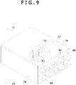
- An electrical component case 77 consists of a square-frame case body 78 which can surround an outer periphery of all the electrical components 71, and a top cover 79.
- a bottom peripheral edge of the case body 78 is fixed to the top surface of the body plate 51 on the other side in the right-and-left direction, and the top opening thereof is detachably blocked with the plate-shaped top cover 79 to form the electrical component case 77.
- the plurality of electrical components 71 (see FIG. 9 ), such as fuses, bus bars, contactors, are detachably arranged inside the electrical component case 77.
- FIG. 9 shows a portion of the electrical components 71. This allows the electrical components 71 to be protected from splashing rainwater if rainwater should enter into the covered space S. By removing the top cover 79 after drawing out the plate member 50, it is possible to access the electrical components 71 inside the case body 78.
- the inverters 72 and electrical components 71 located inside the covered space S are less apt to be seen from the outside, the vehicle can be improved in appearance when in use.
- the plurality of batteries 41 are located at the rear side of the plate member 50.
- the plate member 50 is configured to be drawable in front of the battery 41, and is drawably guided from a position inside the covered space S to a position outside the covered space S by the guide 75 (see FIG. 3 ) described below. This improves the workability of repairs and maintenance on the inverters 72 and electrical components 71 as described below.
- a plurality of connectors 80, 81, 82 are provided at the rear end of the electrical component case 77 with each protruding from a surface of the rear end.
- the plurality of connectors 80, 81, 82 include first connectors 80 which are connected to the three batteries 41 via a first electric wire T1 (see FIG. 2 ).
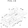
- the first electric wire T1 passes through the inside of the battery cover 42 and the inside of the support base 48 fixed on the front side of the battery cover 42, and leads to the side of the electrical component case 77 through an opening 48b (see FIG. 10 ) formed in a front end plate 48a (see FIG. 10 ) provided at the front end of the support base 48 to be connected to the first connector 80.
- the first connector 80 allows the first connector 80 to be connected to the battery 41 via the first electric wire T1.
- the first connector 80 is connected to the electrical component 71 inside the electrical component case 77. This makes it possible to shorten a length of the first electric wire T1 to connect the battery 41 and the electrical components 71, and facilitates arrangement of the first electric wire T1. This reduces the cost of the first electric wire T1, and lowers the noise and electrical resistance between the battery 41 and the electrical component 71.
- the plurality of connectors 80, 81, 82 include a plurality of second connectors 81 connected to the plurality of electric motors 70 via the inverters 72 and a second wire (not shown), and a plurality of third connectors 82 connected to the controller via a third wire (not shown).
- the controller is installed in a space whose top is covered, such as the covered space S or the like, and is connected to a contactor inside the electrical component case 77 via the third connector 82 to control on/off of the contactor.
- a charging port 83 is provided on a front end surface and protrudes from the front end surface, which is a front side surface of the electrical component case 77 in the drawing-out direction of the electrical component case 77.
- the charging port 83 is provided to connect with a charger (not shown) connected to a commercial AC power supply as an external power source, via a charging cable (not shown).
- the charging port 83 is connected to the contactor and the bus bar inside the electrical component case 77, and then connected to the first connector 80 which is connected to the battery 41.
- a control of on-and-off switching of a plurality of contactors by the controller enables switching between charging the battery 41 with the commercial AC power source and transmitting electric power from the battery 41 to the electric motor 70.
- the plate member 50 has a front end plate 52 bent upward at the front end of the body plate 51.
- a nut 52a is fixed to a front surface of the front end plate 52 at a position where the nut faces the lid knob 49a when the lid 49 is closed.
- a shaft of the lid knob 49a is provided with a rear end having a threaded portion, which projects from a rear surface of the lid 49 to the rear side.
- the plate member 50 for drawably guiding the plate member 50 and the guide 75 is described below.
- the plate member 50 has left and right end plates 53, 54 which are bent downwardly at left and right ends of the body plate 51, respectively.
- the left end plate 53 has a plurality of shafts, which protrude from a plurality of side positions of the left end plate 53 in the front-and-rear direction to the outside in the left direction, and first rollers 55 are rotatably supported on the shafts, respectively.
- the right end plate 54 has a plurality of shafts, which protrude from a plurality of side positions of the right end plate 54 in the front-and-rear direction to the outside in the right direction, and second rollers 56 (see FIG. 3 ) are rotatably supported on the shafts, respectively.
- the plate member 50 includes the first rollers 55 and the second rollers 56 which are rotatably provided on both end portions in a direction orthogonal to the drawing-out direction.
- the guide 75 is supported and fixed to drawably guide the plate member 50 from a position inside the covered space S to a position outside the covered space S, which is in front of the covered space S.
- the guide 75 has a left first guide 84 (see FIG. 6 ) to guide the movement of the plurality of first rollers 55 and a right second guide 87 (see FIG. 6 ) to guide the movement of the plurality of second rollers 56.
- the first guide 84 extends long in the drawing-out direction of the front side, and is a rail having a horizontally U-shaped cross section as shown in FIG. 4 .
- the first guide has two first plates 85 at positions sandwiching the plurality of first rollers 55, which are divided vertically and parallel with each other, and a first coupler 86 to couple left ends of the two first plates 85.
- the second guide 87 extends long in the drawing-out direction of the front side.
- the second guide has two second plates 88 (see FIG.
- the first guide 84 has the first coupler 86 fixed to the inner surface of the left main frame 16a, and the first rollers 55 run on the lower first plate 85.
- the second guide 87 has the second coupler 89 fixed to the inner surface of the right main frame 16b, and the second rollers 56 run on the lower second plate 88. This allows the plate member 50 to be easily drawn out from the position inside the covered space S with light force without running off, thereby further improving workability when performing repair and maintenance work as described below.
- rectangular recesses 91a, 91b are formed at a plurality of positions in a longitudinal direction of the upper first and second plate members 85, 88, where a portion of the guides 84, 87 are positioned inside the covered space S. This allows the plate member 50 to be assembled to the guide 75 so that the rollers 55, 56 can be arranged inside the guides 84, 87 from above in FIG. 10 while preventing the rollers 55, 56 attached to the left and right ends of the plate member 50 from interfering with the guides 84, 87.
- the guides 84, 87 extend to near the front ends of the main frames 16a, 16b, respectively.
- a floor cover 90 is assembled to the front side of the electric vehicle 10 to place on the two main frames 16a, 16b and the lateral frame 16c at the front side so that the front portions of guides 84, 87 are invisible from the outside.
- the floor cover 90 can be made of resin to reduce its weight. This enables the operator to easily remove the floor cover 90 as described below.
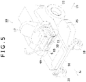
- FIG. 5 is a perspective view of the electric vehicle 10 with the lid 49 being opened.
- the operator can grip the lid knob 49a (see FIG. 1B ) and open the lid 49 upwardly as shown in FIG. 5 .
- FIG. 6 is a perspective view of the electric vehicle with the floor cover 90 being removed in the state shown in FIG. 5 .
- the operator can remove the floor cover 90 in the state shown in FIG. 5 to expose the front portions of the guides 84, 87 to the outside.
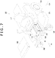
- FIG. 7 is a perspective view of the electric vehicle with the plate member 50 being drawn out in the state shown in FIG. 6 .
- FIG. 8 is a partially enlarged diagram illustrating an area D of FIG. 7 .
- FIG. 9 is a perspective view of the electrical component case 77 as viewed from the rear side with a portion of the top cover 79 being transparent.
- FIG. 10 is a front side enlarged diagram of the electric vehicle with the seat 17 being removed in the state shown in FIG. 7 . After the state shown in FIG.
- the operator can draw the plate member 50 out of the position inside the covered space S to the position in front of the covered space S while rolling the rollers 55, 56 on the guides 84, 87 to expose the electrical component case 77 and the plurality of inverters 72 to a large space outside the covered space.
- the operator can perform the repair or maintenance of the electrical components 71 and the inverters 72 in the large space.
- it is only necessary to remove the top cover 79 of the electrical component case 77 with the electrical components 71 and inverters 72 being mounted on the vehicle.
- the inverters 72 and the electrical components 71 are placed inside the covered space S whose top is covered in a normal operation condition, it is possible to protect the electrical components 71 and the inverters 72 from splashing rainwater, and to improve the appearance when in use because the inverters 72 and the electrical components 71 are less apt to be seen from outside. Furthermore, when performing the repair or maintenance, since the plate member 50 to which the inverters 72 and electrical components 71 are attached can be drawn out into a large space outside the covered space S, the workability of the repair and maintenance is improved.
- a space under the seat 17 can be used effectively by placing the plate member 50 inside the covered space S under the seat 17, it is possible to eliminate or reduce parts dedicated to protecting the inverters 72 and electrical components 71 from splashing rainwater.
- the electrical components 71 are placed inside the electrical component case 77, and the electrical component case 77 has the charging port 83 on the front side surface in the drawing-out direction, and the electrical components 71 are connected to the battery 41.
- the charging port 83 being connected to the electrical components 71 inside the electrical component case 77, the charging cable connected to the commercial AC power source can be connected to the charging port 83 to charge the battery 41 via the electrical components 71 without drawing out the plate member 50 from the covered space S with only the lid 49 being opened, as shown in FIG. 5 , for example.
- the guides 84, 87 have a horizontally U-shaped cross section to guide the movement of the rollers, but the configuration of the guides is not limited thereto.
- either or both of guides 84, 87 and the plate member 50 may be made of resin to slide more easily.
- the guides 84, 87 limit the direction of movement of the plate member 50 only to the longitudinal direction of the guide elements 84, 87, a vertical movement transmitted to the plate member 50 from the ground during traveling is received with the guides 84, 87, so that flapping of the plate member in the covered space S can be suppressed.
- the guides may be anything capable of guiding the movement of the plate member 50.
- the guides may be configured to be a long guide element disposed along the front-and-rear direction at the center of the right-and-left direction of the vehicle with a groove being opened toward the plate member 50.
- the plate member 50 may be configured to have a protruding part formed on the surface facing the groove along the longitudinal direction so that the protruding part can be slidably inserted into the groove.
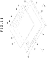
- FIG. 11 is a perspective view illustrating the plate member 50 and a unit case 92 to be mounted on the electric vehicle according to an alternative example of the embodiment.
- the unit case 92 is formed by removably closing with a plate member-shaped top cover 94 a top end opening of a substantially rectangular frame-shaped case body 93 whose top end is opened. A bottom end periphery of the case body 93 is fixed to the top surface of the plate member 50.
- the plurality of connectors 80, 81, 82 are provided, with each protruding from the rear end of the unit case 92.
- the charging port 83 is provided at the front end of the unit case 92.
- FIG. 12 is a side view of a rear portion of the electric vehicle 10 according to alternative example of the embodiment in which a portion thereof is illustrated as a cross sectional view.
- FIG. 13 is a cross sectional view taken along line E-E of FIG. 12 .
- the support base is removed from the inside of the seat frame 45, and a length of the seat frame 45 in the front-and-rear direction is shortened.
- an extension part 42b extending in the front side is provided on the front upper side of a battery cover 42a.
- the plate member 50 is placed in front of the plurality of batteries 41 inside the battery cover 42a and inside the extension part 42b so that it can be drawn out from the top end of the battery cover 42a to an upside from the vehicle body.
- the plate member 50 to be positioned between the battery 41 and the seat 17 and to be drawn out to the upside from the vehicle body.
- the plurality of electrical components 71 (see FIG. 9 ) and the plurality of inverters 72 are detachably mounted on the rear side of the plate member 50.
- the top, bottom, left, right, and rear sides of the electrical components 71 are covered with the electrical component case 77 in a manner similar to the embodiment of FIG. 8 mentioned above.
- All of the electrical components 71 and the plurality of inverters 72 may be covered and enclosed by the unit case in a manner similar to the embodiment of FIG. 11 mentioned above.
- the plurality of first rollers 55 and second rollers 56 are rotatably attached to the left and right end surfaces of the plate member 50, respectively.
- the plate member 50 itself has the same configuration as the plate member illustrated in FIGS. 1 through 10 , except that the orientation of the plate member 50 is changed from the front-and-rear direction to the vertical direction.
- the first guide 84 and the second guide 87 which constitute the guide 75a, are fixed to the left and right inner end surfaces of the extension part 42b of the battery cover 42a so as to extend in the vertical direction, respectively.
- Each of the guides 84, 87 itself has the same configuration as the corresponding guide illustrated in FIGS.
- the top end opening of the battery cover 42a including the extension part 42b is removably closed by the top cover 42c to prevent invasion of rainwater and dust and to protect the electrical components 71, the plurality of inverters 72, and the batteries 41.
- the covered space S is formed inside the extension part 42b of the battery cover 42a. A backrest of the seat 17 can be pivoted toward the front side.
- the backrest of the seat 17 is tilted and retreated forward from an upper side of the battery cover 42a in a state of removing of the top cover 42c from the top of the battery cover 42a.
- the plate member 50 is drawn out upwardly while being guided with the guide 75a to expose the electrical component case 77 and the inverters 72 outside the battery cover 42a.
- the operator can perform the repair or maintenance of the electrical components 71 and the inverters 72 in the large space.
- the battery cover 42a has hooks or stopper pins (not shown) which can temporarily engage with the plate member 50 in order to hold the plate member 50 at an upwardly drawn out position and at an accommodated position at which the plate member 50 is accommodated inside the battery cover 42a.
- hooks or stopper pins (not shown) which can temporarily engage with the plate member 50 in order to hold the plate member 50 at an upwardly drawn out position and at an accommodated position at which the plate member 50 is accommodated inside the battery cover 42a.
- the electric wire T1 connecting the connectors 80 to the battery 41 can be shortened by placing the connectors 80 to connect the electrical components 71 to the battery 41 in the vicinity of the bottom end of the plate member 50. This reduces the cost of the electric wire T1, and decreases the noise and electrical resistance between the battery 41 and the electrical components 71.
- the other configurations and actions of this example are the same as those of the embodiment shown in FIGS. 1 through 10 .
- FIG. 14 is a side view of a front portion of the electric vehicle 10 according to alternative example of the embodiment in which a portion thereof is illustrated as a cross sectional view.
- a hood 100 is fixed to the body frame 16 in front of the seat 17.
- the covered space S whose top is covered with the hood 100, is provided under the hood 100.
- the hood 100 has a box-like shape with its bottom end being opened.
- a steering operation shaft 102 penetrates through the top plate upward obliquely.
- a steering wheel 103 is attached to a top end of the steering operation shaft 102.
- a gear mechanism which is connected to a steering mechanism (not shown) to steer left and right front wheels 105, is connected at the bottom end of the steering operation shaft 102.
- the orientation of the front two wheels 105 is changed by rotating the steering wheel 103.
- a motor (not shown) is fixed to the rear side of the body frame 16, and driving power of an output shaft of the motor is transmitted to the rear two wheels 24 via an axle drive unit (not shown) having a differential mechanism.
- a partition plate 106 is horizontally fixed inside the hood 100 at the middle part in the vertical direction.
- One or more batteries 41 are mounted on the partition plate 106. This allows the batteries 41 to be placed in front of the seat with being covered by the hood 100.
- the electrical component case 77 containing electrical components and a plurality of inverters are fixed side by side along the right-and -left direction of the vehicle.
- the left side first guide 84 forming the guide 75 and the right side second guide 87 are supported and fixed on the inner side faces of the left and right main frames 16a, 16b in a vehicle-wide direction, respectively.
- Each of the guides 84, 87 is formed by coupling along the front-and-rear direction a portion inside the covered space S and a portion located on the rear side of the covered space S.
- the guide 75 drawably guides the plate member 50 from a position inside the covered space S to a position outside of and on the rear side of the covered space S. This allows the plate member 50 to be placed in the covered space S and to be drawn out from the inside of the covered space S to the rear side thereof, which is one side in the front-and-rear direction.
- the configuration of the guide 75 of this example is the same as that of the guide 75 of the embodiment shown in FIGS. 1 through 10 .
- the lid 49 which can be opened and closed, is provided at the lower side of the rear end of the hood 100.
- a rear end plate 107 is formed so as to rise up vertically.
- the nut 52a is fixed to a rear side surface of the rear end plate 107, so that the nut 52a faces the lid knob 49a when the lid 49 is closed.
- a shaft of the lid knob 49a is provided with a front end having a threaded portion, which projects from a front side surface of the lid 49 to the front side.
- the floor plate 108 is assembled to the main frame 16a or a member fixed to the main frame 16a at a portion of each of guides 84, 87 located between the hood 100 and a seat frame 45a to which the seat 17 is fixed. This makes the guides 84, 87 are less apt to be seen from the outside in a normal operation condition.
- the operator may draw out the plate member 50a from a position in the covered space S to a position on the rear side of the covered space S along each of the guides 84, 87 after removing the floor plate 108 from the vehicle.
- This allows the electrical component case 77 and the plurality of inverters to be exposed to a large outside space.
- the operator can perform the repair or maintenance of the electrical components and the inverters in the large space.
- the configuration of this example it is possible to share the parts with a vehicle with an engine by providing the battery 41 in place of the engine in the vehicle with the engine which is located inside the hood 100 as a driving source of the vehicle. Furthermore, an extra space inside the hood 100 can be used as a space to accommodate the inverters and the electrical component case 77 in which the electrical components are enclosed.
- the lid which can be opened and closed, is provided on the lower side of a front end plate of the hood, the plate member to which the inverters and electrical component case are fixed may be drawn out to a front side of the hood 100 by the guides with the lid being opened. In this case, one side in the front-and-rear direction designates the front side.
- the other configurations and actions of this example are the same as those of the embodiment shown in FIGS. 1 through 10 .
- At least one embodiment mentioned above has the configuration of the electric vehicle of the present disclosure.
- the inverters and the electrical components are placed inside the covered space whose top is covered in a normal operation condition, it is possible to protect the electrical components and the inverters from splashing rainwater, as well as improve the appearance when in use because the inverters and the electrical components are less apt to be seen from outside.
- the plate member to which the inverters and electrical components are attached can be drawn out into a large space outside the covered space, workability of the repair and maintenance is improved.
- JP 2018-184035 A when performing the repair or maintenance, differing from a configuration disclosed in JP 2018-184035 A , in which a box containing the inverters and electrical components is detachably provided at a fixed position set under the seat on the vehicle body, it is not necessary to separate the seat from its mounted position on the electric vehicle and to temporarily remove the heavy storage box from the vehicle at the time of maintenance of electrical components, and the like. This further improves the workability of the repair and maintenance.
- the plate member may be placed in the covered space under the seat to be drawn out to one side along a front-and-rear direction of the vehicle. According to the configuration mentioned above, while the space under the seat can be used effectively, it is possible to eliminate or reduce parts dedicated to protecting the inverters and electrical components from splashing rainwater.
- the electrical components may be placed inside the electrical component case, the electrical component case may have the charging port on the front side surface in the drawing-out direction, and the electrical components may be connected to the battery.
- the charging port since the charging port is connected to the electrical components inside the electrical component case, the charging cable connected to an external power source can be connected to the charging port to charge the battery via the electrical components without drawing out the plate member from the covered space.
- the electric vehicle of the present disclosure may be configured so that: the battery is disposed on the rear side of the plate member; the plate member is drawable in front of the battery; the electrical components are disposed in the electrical component case; the electrical component case is provided with a connector connected to the electrical components at the rear end; and the connector is connected to the battery with an electric wire.
- This configuration enables shortening of a length of the electric wire to connect the battery and the electrical components, and facilitates arrangement of the same. This reduces the cost of the electric wire, and decreases the noise and electrical resistance between the battery and the electrical components.
- the electric vehicle of the present disclosure may be configured so that the inverters and the electrical components are disposed in a common case and the case is mounted on the plate member. According to the configuration mentioned above, waterproof and dustproof characteristics of the inverters and the electrical components can be improved.
- the electric vehicle of the present disclosure may be configured so that: the battery is disposed on the rear side of the seat; and the plate member is located between the battery and the seat and be operable to be drawn out above the vehicle.
- the electric wire connecting the connectors and the battery can be shortened by placing the connectors to connect the electrical components to the battery in the vicinity of the plate member. This reduces the cost of the electric wire, and decreases the noise and electrical resistance between the battery and the electrical components.
- the electric vehicle of the present disclosure may be configured so that: the plate member has a first roller and a second roller which are rotatably attached to both end portions in a direction orthogonal to a drawing-out direction, the guide includes a first guide extending long in the drawing-out direction, which has two first plates provided in parallel with each other to sandwich the first roller and a first coupler to couple the two first plates, and a second guide extending long in the drawing-out direction, which has two second plates provided in parallel with each other to sandwich the second roller and a second coupler to couple the two second plates.
- the above mentioned configuration allows the plate member to be easily drawn out from the position inside the covered space, thereby further improving the workability of repair and maintenance.
- the electric vehicle of the present disclosure may be configured so that: the battery is disposed in front of the seat covered by the hood; and the plate member is located inside the covered space under the hood to be drawn out to one side in the front-and-rear direction.
- the battery when the battery is installed in place of the engine in the vehicle in which the engine is mounted in the hood as a driving source for the wheels, an extra space inside the hood can be used as a space to accommodate the inverters and the electrical components.
Landscapes
- Engineering & Computer Science (AREA)
- Life Sciences & Earth Sciences (AREA)
- Environmental Sciences (AREA)
- Chemical & Material Sciences (AREA)
- Combustion & Propulsion (AREA)
- Transportation (AREA)
- Mechanical Engineering (AREA)
- Arrangement Or Mounting Of Propulsion Units For Vehicles (AREA)
- Harvester Elements (AREA)
- Electric Propulsion And Braking For Vehicles (AREA)
Applications Claiming Priority (1)
| Application Number | Priority Date | Filing Date | Title |
|---|---|---|---|
| JP2021024600A JP2022126494A (ja) | 2021-02-18 | 2021-02-18 | 電動車両 |
Publications (2)
| Publication Number | Publication Date |
|---|---|
| EP4046840A1 true EP4046840A1 (fr) | 2022-08-24 |
| EP4046840B1 EP4046840B1 (fr) | 2025-04-02 |
Family
ID=80953478
Family Applications (1)
| Application Number | Title | Priority Date | Filing Date |
|---|---|---|---|
| EP22157082.3A Active EP4046840B1 (fr) | 2021-02-18 | 2022-02-16 | Véhicule électrique |
Country Status (3)
| Country | Link |
|---|---|
| US (1) | US12161061B2 (fr) |
| EP (1) | EP4046840B1 (fr) |
| JP (1) | JP2022126494A (fr) |
Families Citing this family (1)
| Publication number | Priority date | Publication date | Assignee | Title |
|---|---|---|---|---|
| US12606000B2 (en) * | 2023-10-13 | 2026-04-21 | Kubota Corporation | Work vehicle with vertically overlapping battery housings |
Citations (3)
| Publication number | Priority date | Publication date | Assignee | Title |
|---|---|---|---|---|
| US20080264026A1 (en) * | 2007-04-24 | 2008-10-30 | Kanzaki Kokyukoki Manufacturing Co., Ltd. | Riding lawnmower vehicle |
| JP2018184035A (ja) | 2017-04-24 | 2018-11-22 | 株式会社クボタ | 作業車 |
| CN110771352A (zh) * | 2019-12-05 | 2020-02-11 | 常州格力博有限公司 | 割草机及其电池包组件 |
Family Cites Families (5)
| Publication number | Priority date | Publication date | Assignee | Title |
|---|---|---|---|---|
| US10130037B2 (en) * | 2014-12-31 | 2018-11-20 | Mean Green Products, LLC | Electric mower apparatus and method of use |
| US10029551B2 (en) * | 2015-11-16 | 2018-07-24 | Kubota Corporation | Electric work vehicle, battery pack for electric work vehicle and contactless charging system |
| JP7178955B2 (ja) * | 2019-05-14 | 2022-11-28 | 株式会社クボタ | 電動作業車用バッテリパック |
| JP7323349B2 (ja) * | 2019-06-24 | 2023-08-08 | 株式会社クボタ | 電動作業車 |
| JP7173944B2 (ja) * | 2019-10-08 | 2022-11-16 | 株式会社クボタ | 電動作業車 |
-
2021
- 2021-02-18 JP JP2021024600A patent/JP2022126494A/ja active Pending
-
2022
- 2022-02-16 EP EP22157082.3A patent/EP4046840B1/fr active Active
- 2022-02-17 US US17/674,322 patent/US12161061B2/en active Active
Patent Citations (3)
| Publication number | Priority date | Publication date | Assignee | Title |
|---|---|---|---|---|
| US20080264026A1 (en) * | 2007-04-24 | 2008-10-30 | Kanzaki Kokyukoki Manufacturing Co., Ltd. | Riding lawnmower vehicle |
| JP2018184035A (ja) | 2017-04-24 | 2018-11-22 | 株式会社クボタ | 作業車 |
| CN110771352A (zh) * | 2019-12-05 | 2020-02-11 | 常州格力博有限公司 | 割草机及其电池包组件 |
Also Published As
| Publication number | Publication date |
|---|---|
| US20220256766A1 (en) | 2022-08-18 |
| US12161061B2 (en) | 2024-12-10 |
| EP4046840B1 (fr) | 2025-04-02 |
| JP2022126494A (ja) | 2022-08-30 |
Similar Documents
| Publication | Publication Date | Title |
|---|---|---|
| CN111902337B (zh) | 电动车辆 | |
| US11069936B2 (en) | Electric work vehicle | |
| CN111886176B (zh) | 电动车辆 | |
| CN111902336B (zh) | 电动车辆 | |
| JP6764910B2 (ja) | 車両 | |
| CN111114676B (zh) | 跨骑型电动车辆 | |
| KR20130101554A (ko) | 전동 차량 구동 장치 | |
| JP7482080B2 (ja) | 作業車両 | |
| US20240130289A1 (en) | Vehicle | |
| EP4046840B1 (fr) | Véhicule électrique | |
| US12377929B2 (en) | Vehicle | |
| JP2013014274A (ja) | 電気自動車のバッテリ支持構造 | |
| JP6842994B2 (ja) | モーアユニット | |
| JP2018012464A (ja) | 電動作業車 | |
| JP2024068541A (ja) | 電動アシスト台車 | |
| WO2023112793A1 (fr) | Véhicule de travail électrique | |
| US4817748A (en) | Industrial vehicle equipped with electrically powered power steering system | |
| JP2023088200A (ja) | 電動作業車 | |
| JP6606463B2 (ja) | 作業車 | |
| JP7555326B2 (ja) | 電動作業車 | |
| EP4260679B1 (fr) | Tondeuse à gazon autoportée | |
| JP2024120565A (ja) | 作業車両 | |
| JP2023156641A (ja) | 作業車両 | |
| JP2024164319A5 (fr) | ||
| JP2023156640A (ja) | 作業車両 |
Legal Events
| Date | Code | Title | Description |
|---|---|---|---|
| PUAI | Public reference made under article 153(3) epc to a published international application that has entered the european phase |
Free format text: ORIGINAL CODE: 0009012 |
|
| STAA | Information on the status of an ep patent application or granted ep patent |
Free format text: STATUS: THE APPLICATION HAS BEEN PUBLISHED |
|
| AK | Designated contracting states |
Kind code of ref document: A1 Designated state(s): AL AT BE BG CH CY CZ DE DK EE ES FI FR GB GR HR HU IE IS IT LI LT LU LV MC MK MT NL NO PL PT RO RS SE SI SK SM TR |
|
| STAA | Information on the status of an ep patent application or granted ep patent |
Free format text: STATUS: REQUEST FOR EXAMINATION WAS MADE |
|
| 17P | Request for examination filed |
Effective date: 20230222 |
|
| RBV | Designated contracting states (corrected) |
Designated state(s): AL AT BE BG CH CY CZ DE DK EE ES FI FR GB GR HR HU IE IS IT LI LT LU LV MC MK MT NL NO PL PT RO RS SE SI SK SM TR |
|
| RIC1 | Information provided on ipc code assigned before grant |
Ipc: B60K 1/04 20190101AFI20240819BHEP |
|
| GRAP | Despatch of communication of intention to grant a patent |
Free format text: ORIGINAL CODE: EPIDOSNIGR1 |
|
| STAA | Information on the status of an ep patent application or granted ep patent |
Free format text: STATUS: GRANT OF PATENT IS INTENDED |
|
| INTG | Intention to grant announced |
Effective date: 20241002 |
|
| RIN1 | Information on inventor provided before grant (corrected) |
Inventor name: KONO, DAISUKE Inventor name: ARATA, MASATO Inventor name: OGURA, KOHEI Inventor name: NISHIZAWA, TAKASHI |
|
| P01 | Opt-out of the competence of the unified patent court (upc) registered |
Free format text: CASE NUMBER: APP_62655/2024 Effective date: 20241125 |
|
| GRAS | Grant fee paid |
Free format text: ORIGINAL CODE: EPIDOSNIGR3 |
|
| GRAA | (expected) grant |
Free format text: ORIGINAL CODE: 0009210 |
|
| STAA | Information on the status of an ep patent application or granted ep patent |
Free format text: STATUS: THE PATENT HAS BEEN GRANTED |
|
| AK | Designated contracting states |
Kind code of ref document: B1 Designated state(s): AL AT BE BG CH CY CZ DE DK EE ES FI FR GB GR HR HU IE IS IT LI LT LU LV MC MK MT NL NO PL PT RO RS SE SI SK SM TR |
|
| REG | Reference to a national code |
Ref country code: GB Ref legal event code: FG4D |
|
| REG | Reference to a national code |
Ref country code: CH Ref legal event code: EP |
|
| REG | Reference to a national code |
Ref country code: IE Ref legal event code: FG4D |
|
| REG | Reference to a national code |
Ref country code: DE Ref legal event code: R096 Ref document number: 602022012429 Country of ref document: DE |
|
| REG | Reference to a national code |
Ref country code: NL Ref legal event code: MP Effective date: 20250402 |
|
| PG25 | Lapsed in a contracting state [announced via postgrant information from national office to epo] |
Ref country code: NL Free format text: LAPSE BECAUSE OF FAILURE TO SUBMIT A TRANSLATION OF THE DESCRIPTION OR TO PAY THE FEE WITHIN THE PRESCRIBED TIME-LIMIT Effective date: 20250402 |
|
| REG | Reference to a national code |
Ref country code: AT Ref legal event code: MK05 Ref document number: 1780971 Country of ref document: AT Kind code of ref document: T Effective date: 20250402 |
|
| PG25 | Lapsed in a contracting state [announced via postgrant information from national office to epo] |
Ref country code: FI Free format text: LAPSE BECAUSE OF FAILURE TO SUBMIT A TRANSLATION OF THE DESCRIPTION OR TO PAY THE FEE WITHIN THE PRESCRIBED TIME-LIMIT Effective date: 20250402 Ref country code: PT Free format text: LAPSE BECAUSE OF FAILURE TO SUBMIT A TRANSLATION OF THE DESCRIPTION OR TO PAY THE FEE WITHIN THE PRESCRIBED TIME-LIMIT Effective date: 20250804 Ref country code: ES Free format text: LAPSE BECAUSE OF FAILURE TO SUBMIT A TRANSLATION OF THE DESCRIPTION OR TO PAY THE FEE WITHIN THE PRESCRIBED TIME-LIMIT Effective date: 20250402 |
|
| REG | Reference to a national code |
Ref country code: LT Ref legal event code: MG9D |
|
| PG25 | Lapsed in a contracting state [announced via postgrant information from national office to epo] |
Ref country code: NO Free format text: LAPSE BECAUSE OF FAILURE TO SUBMIT A TRANSLATION OF THE DESCRIPTION OR TO PAY THE FEE WITHIN THE PRESCRIBED TIME-LIMIT Effective date: 20250702 Ref country code: GR Free format text: LAPSE BECAUSE OF FAILURE TO SUBMIT A TRANSLATION OF THE DESCRIPTION OR TO PAY THE FEE WITHIN THE PRESCRIBED TIME-LIMIT Effective date: 20250703 |
|
| PG25 | Lapsed in a contracting state [announced via postgrant information from national office to epo] |
Ref country code: PL Free format text: LAPSE BECAUSE OF FAILURE TO SUBMIT A TRANSLATION OF THE DESCRIPTION OR TO PAY THE FEE WITHIN THE PRESCRIBED TIME-LIMIT Effective date: 20250402 |
|
| PG25 | Lapsed in a contracting state [announced via postgrant information from national office to epo] |
Ref country code: BG Free format text: LAPSE BECAUSE OF FAILURE TO SUBMIT A TRANSLATION OF THE DESCRIPTION OR TO PAY THE FEE WITHIN THE PRESCRIBED TIME-LIMIT Effective date: 20250402 |
|
| PG25 | Lapsed in a contracting state [announced via postgrant information from national office to epo] |
Ref country code: HR Free format text: LAPSE BECAUSE OF FAILURE TO SUBMIT A TRANSLATION OF THE DESCRIPTION OR TO PAY THE FEE WITHIN THE PRESCRIBED TIME-LIMIT Effective date: 20250402 |
|
| PG25 | Lapsed in a contracting state [announced via postgrant information from national office to epo] |
Ref country code: AT Free format text: LAPSE BECAUSE OF FAILURE TO SUBMIT A TRANSLATION OF THE DESCRIPTION OR TO PAY THE FEE WITHIN THE PRESCRIBED TIME-LIMIT Effective date: 20250402 |
|
| PG25 | Lapsed in a contracting state [announced via postgrant information from national office to epo] |
Ref country code: RS Free format text: LAPSE BECAUSE OF FAILURE TO SUBMIT A TRANSLATION OF THE DESCRIPTION OR TO PAY THE FEE WITHIN THE PRESCRIBED TIME-LIMIT Effective date: 20250702 |
|
| PG25 | Lapsed in a contracting state [announced via postgrant information from national office to epo] |
Ref country code: IS Free format text: LAPSE BECAUSE OF FAILURE TO SUBMIT A TRANSLATION OF THE DESCRIPTION OR TO PAY THE FEE WITHIN THE PRESCRIBED TIME-LIMIT Effective date: 20250802 |
|
| PG25 | Lapsed in a contracting state [announced via postgrant information from national office to epo] |
Ref country code: LV Free format text: LAPSE BECAUSE OF FAILURE TO SUBMIT A TRANSLATION OF THE DESCRIPTION OR TO PAY THE FEE WITHIN THE PRESCRIBED TIME-LIMIT Effective date: 20250402 |
|
| REG | Reference to a national code |
Ref country code: DE Ref legal event code: R097 Ref document number: 602022012429 Country of ref document: DE |
|
| PG25 | Lapsed in a contracting state [announced via postgrant information from national office to epo] |
Ref country code: DK Free format text: LAPSE BECAUSE OF FAILURE TO SUBMIT A TRANSLATION OF THE DESCRIPTION OR TO PAY THE FEE WITHIN THE PRESCRIBED TIME-LIMIT Effective date: 20250402 Ref country code: SM Free format text: LAPSE BECAUSE OF FAILURE TO SUBMIT A TRANSLATION OF THE DESCRIPTION OR TO PAY THE FEE WITHIN THE PRESCRIBED TIME-LIMIT Effective date: 20250402 |
|
| PG25 | Lapsed in a contracting state [announced via postgrant information from national office to epo] |
Ref country code: CZ Free format text: LAPSE BECAUSE OF FAILURE TO SUBMIT A TRANSLATION OF THE DESCRIPTION OR TO PAY THE FEE WITHIN THE PRESCRIBED TIME-LIMIT Effective date: 20250402 |
|
| PG25 | Lapsed in a contracting state [announced via postgrant information from national office to epo] |
Ref country code: EE Free format text: LAPSE BECAUSE OF FAILURE TO SUBMIT A TRANSLATION OF THE DESCRIPTION OR TO PAY THE FEE WITHIN THE PRESCRIBED TIME-LIMIT Effective date: 20250402 |
|
| PG25 | Lapsed in a contracting state [announced via postgrant information from national office to epo] |
Ref country code: SK Free format text: LAPSE BECAUSE OF FAILURE TO SUBMIT A TRANSLATION OF THE DESCRIPTION OR TO PAY THE FEE WITHIN THE PRESCRIBED TIME-LIMIT Effective date: 20250402 |
|
| PG25 | Lapsed in a contracting state [announced via postgrant information from national office to epo] |
Ref country code: IT Free format text: LAPSE BECAUSE OF FAILURE TO SUBMIT A TRANSLATION OF THE DESCRIPTION OR TO PAY THE FEE WITHIN THE PRESCRIBED TIME-LIMIT Effective date: 20250402 |
|
| PLBE | No opposition filed within time limit |
Free format text: ORIGINAL CODE: 0009261 |
|
| STAA | Information on the status of an ep patent application or granted ep patent |
Free format text: STATUS: NO OPPOSITION FILED WITHIN TIME LIMIT |
|
| REG | Reference to a national code |
Ref country code: CH Ref legal event code: L10 Free format text: ST27 STATUS EVENT CODE: U-0-0-L10-L00 (AS PROVIDED BY THE NATIONAL OFFICE) Effective date: 20260211 |
|
| 26N | No opposition filed |
Effective date: 20260105 |
|
| PGFP | Annual fee paid to national office [announced via postgrant information from national office to epo] |
Ref country code: DE Payment date: 20260218 Year of fee payment: 5 |