EP4046754B1 - Elektrowerkzeug und elektrische steuerungsanordnung dafür - Google Patents
Elektrowerkzeug und elektrische steuerungsanordnung dafür Download PDFInfo
- Publication number
- EP4046754B1 EP4046754B1 EP20910134.4A EP20910134A EP4046754B1 EP 4046754 B1 EP4046754 B1 EP 4046754B1 EP 20910134 A EP20910134 A EP 20910134A EP 4046754 B1 EP4046754 B1 EP 4046754B1
- Authority
- EP
- European Patent Office
- Prior art keywords
- electronic control
- circuit board
- mounting base
- power tool
- control assembly
- Prior art date
- Legal status (The legal status is an assumption and is not a legal conclusion. Google has not performed a legal analysis and makes no representation as to the accuracy of the status listed.)
- Active
Links
Images


Classifications
-
- H—ELECTRICITY
- H02—GENERATION; CONVERSION OR DISTRIBUTION OF ELECTRIC POWER
- H02K—DYNAMO-ELECTRIC MACHINES
- H02K11/00—Structural association of dynamo-electric machines with electric components or with devices for shielding, monitoring or protection
- H02K11/0094—Structural association with other electrical or electronic devices
-
- B—PERFORMING OPERATIONS; TRANSPORTING
- B25—HAND TOOLS; PORTABLE POWER-DRIVEN TOOLS; MANIPULATORS
- B25F—COMBINATION OR MULTI-PURPOSE TOOLS NOT OTHERWISE PROVIDED FOR; DETAILS OR COMPONENTS OF PORTABLE POWER-DRIVEN TOOLS NOT PARTICULARLY RELATED TO THE OPERATIONS PERFORMED AND NOT OTHERWISE PROVIDED FOR
- B25F5/00—Details or components of portable power-driven tools not particularly related to the operations performed and not otherwise provided for
- B25F5/02—Construction of casings, bodies or handles
-
- B—PERFORMING OPERATIONS; TRANSPORTING
- B25—HAND TOOLS; PORTABLE POWER-DRIVEN TOOLS; MANIPULATORS
- B25F—COMBINATION OR MULTI-PURPOSE TOOLS NOT OTHERWISE PROVIDED FOR; DETAILS OR COMPONENTS OF PORTABLE POWER-DRIVEN TOOLS NOT PARTICULARLY RELATED TO THE OPERATIONS PERFORMED AND NOT OTHERWISE PROVIDED FOR
- B25F5/00—Details or components of portable power-driven tools not particularly related to the operations performed and not otherwise provided for
- B25F5/008—Cooling means
-
- H—ELECTRICITY
- H02—GENERATION; CONVERSION OR DISTRIBUTION OF ELECTRIC POWER
- H02K—DYNAMO-ELECTRIC MACHINES
- H02K7/00—Arrangements for handling mechanical energy structurally associated with dynamo-electric machines, e.g. structural association with mechanical driving motors or auxiliary dynamo-electric machines
- H02K7/14—Structural association with mechanical loads, e.g. with hand-held machine tools or fans
- H02K7/145—Hand-held machine tool
-
- H—ELECTRICITY
- H02—GENERATION; CONVERSION OR DISTRIBUTION OF ELECTRIC POWER
- H02K—DYNAMO-ELECTRIC MACHINES
- H02K9/00—Arrangements for cooling or ventilating
-
- H—ELECTRICITY
- H05—ELECTRIC TECHNIQUES NOT OTHERWISE PROVIDED FOR
- H05K—PRINTED CIRCUITS; CASINGS OR CONSTRUCTIONAL DETAILS OF ELECTRIC APPARATUS; MANUFACTURE OF ASSEMBLAGES OF ELECTRICAL COMPONENTS
- H05K7/00—Constructional details common to different types of electric apparatus
- H05K7/14—Mounting supporting structure in casing or on frame or rack
- H05K7/1422—Printed circuit boards receptacles, e.g. stacked structures, electronic circuit modules or box like frames
- H05K7/1427—Housings
Definitions
- the present application relates to the technical field of power tools, for example, a power tool and an electronic control assembly thereof.
- US 2019/296608 A1 discloses a power tool according to the preamble of claim 1.
- PCB assembly in the related art has the problems below.
- the PCB assembly is connected to a power supply through a soft connection such as wires. Since connection terminals between wires and electrical elements have relatively poor stability, a connection failure easily occurs during use due to external causes such as vibration or aging, which results in low reliability, affects a service life, and increases a maintenance cost.
- the wiring method of wires is complicated, which is not conducive to arranging structures within a housing and increases the manufacturing difficulty and cost of a production line.
- the PCB assembly in the related art has only basic functions such as control and driving, has a low integration degree, is not compact in structure, and occupies a relatively large space, which is not conducive to the miniaturization and sophistication of the whole machine.
- the present application provides a power tool and an electronic control assembly thereof, which have high reliability and a high integration degree and facilitate size optimization.
- a power tool in an embodiment of the present application, includes: a main body comprising a housing and a motor, a switch assembly, and an electronic control assembly which are mounted in the housing, wherein the electronic control assembly is electrically connected to the switch assembly and the motor, separately; and a battery pack detachably coupled to the main body and having a connection state in which the battery pack is electrically conductive with the electronic control assembly and a separate state in which the battery pack is disconnected from the electronic control assembly.
- the electronic control assembly comprises: an electronic control unit comprising a power circuit board which is made of a metal substrate; a mounting base, wherein the power circuit board is in contact with the mounting base which is a metal base and provided with an opening; and a connecting unit for conductively connecting the battery pack to the electronic control unit, connected to the mounting base via the opening, and mating with the mounting base to form a mounting space in which the electronic control unit is mounted.
- the electronic control unit further includes a control circuit board, where the control circuit board and the power circuit board are stacked within the mounting base.
- the mounting base includes a baseplate and wall plates, where the wall plates are disposed along an edge of the baseplate and provided with the opening.
- the connecting unit includes a connection base and a conduction member disposed on the connection base, where the connection base is pluggably connected to the baseplate via the opening, and the conduction member connects the electronic control assembly to the battery pack.
- the conduction member includes an electronic control conduction member and a power supply conduction member, which are conductively connected to each other, and a conductive limiting member is disposed on the power circuit board, where the conductive limiting member conductively mates with the electronic control conduction member and limits the power circuit board.
- the electronic control assembly further includes a blocking unit which is connected to the wall plates so as to block the opening; and the blocking unit is provided with engaging grooves slidably connected to wall plates on two sides of the opening.
- the mounting base further includes heat dissipation fins disposed on a side of the baseplate facing away from the electronic control unit, and heat dissipation channels are formed between the heat dissipation fins.
- part or all of the heat dissipation fins extend onto the wall plates to form flow guiding fins, flow guiding channels are formed between the flow guiding fins, and the flow guiding channels communicate with the heat dissipation channels.
- the housing is provided with an air inlet and an air outlet, and the flow guiding channels on the mounting base are docked with the air inlet.
- the power tool further includes a displacement compensation unit disposed at a position where an inner wall of the housing is in contact with the electronic control assembly.
- a power tool includes: a main body comprising a housing and a motor, a switch assembly, and an electronic control assembly which are mounted in the housing, wherein the electronic control assembly is electrically connected to the switch assembly and the motor, separately; and a battery pack detachably coupled to the main body and having a connection state in which electricity is conducted between the battery pack and the electronic control assembly and a separate state in which the battery pack is disconnected from the electronic control assembly.
- the electronic control assembly comprises: an electronic control unit comprising a power circuit board; a mounting base provided with an opening; a connecting unit for conductively connecting the battery pack to the electronic control unit, inserted to the mounting base via the opening, and mating with the mounting base to form a mounting space in which the electronic control unit is mounted; and a blocking unit inserted into the opening to prevent a sealant from flowing out from the opening.
- the mounting base includes a baseplate and wall plates, where the wall plates are disposed along an edge of the baseplate and provided with the opening.
- the blocking unit is provided with engaging grooves slidably connected to wall plates on two sides of the opening.
- the electronic control unit further includes a control circuit board, where the control circuit board and the power circuit board are stacked within the mounting base, and the power circuit board is in contact with the mounting base.
- the connecting unit includes a connection base and a conduction member disposed on the connection base, where the connection base is inserted to the baseplate, the conduction member includes an electronic control conduction member and a power supply conduction member, which are conductively connected to each other, and a conductive limiting member is disposed on the power circuit board, where the conduction member conductively mates with the electronic control conduction member and limits the power circuit board.
- the conduction member includes an electronic control conduction member and a power supply conduction member, which are conductively connected to each other, and the conductive limiting member is disposed on the power circuit board, where the conductive limiting member conductively mates with the electronic control conduction member and limits the power circuit board.
- the mounting base further includes heat dissipation fins disposed on a side of the baseplate facing away from the electronic control unit, and heat dissipation channels are formed between the heat dissipation fins.
- part or all of the heat dissipation fins extend onto the wall plates to form flow guiding fins, flow guiding channels are formed between the flow guiding fins, and the flow guiding channels communicate with the heat dissipation channels.
- the housing is provided with an air inlet and an air outlet, and the flow guiding channels on the mounting base are docked with the air inlet.
- the power tool further includes a displacement compensation unit disposed at a position where an inner wall of the housing is in contact with the electronic control assembly.
- a power tool in an embodiment of the present application, includes: a main body comprising a housing and a motor, a switch assembly, and an electronic control assembly which are mounted in the housing, wherein the electronic control assembly is electrically connected to the switch assembly and the motor, separately; and a battery pack detachably coupled to the main body and having a connection state in which electricity is conducted between the battery pack and the electronic control assembly and a separate state in which the battery pack is disconnected from the electronic control assembly.
- the electronic control assembly comprises: an electronic control unit comprising a power circuit board; a mounting base for dissipating heat from at least the power circuit board and provided with a mounting portion; and a connecting unit for conductively connecting the battery pack to the electronic control unit and mating with and connected to the mounting base via the mounting portion to form a mounting space in which the electronic control unit is mounted.
- the electronic control unit further includes a control circuit board, where the control circuit board and the power circuit board are stacked within the mounting base, and the power circuit board is in contact with the mounting base.
- control circuit board and the power circuit board are pluggably connected to each other via electrical connectors.
- the mounting base includes a baseplate and wall plates, where the wall plates are disposed along an edge of the baseplate and provided with an opening, the opening forms the mounting portion, and the connecting unit is inserted to the baseplate via the opening.
- the electronic control assembly further includes a blocking unit which is connected to the wall plates so as to block the opening; and the blocking unit is provided with engaging grooves slidably connected to wall plates on two sides of the opening.
- the connecting unit includes a connection base and a conduction member disposed on the connection base, where the conduction member includes an electronic control conduction member and a power supply conduction member, which are conductively connected to each other; and a conductive limiting member is disposed on the power circuit board, where the conductive limiting member conductively mates with the electronic control conduction member and limits the power circuit board.
- the conductive limiting member includes connection holes disposed on the power circuit board, and the electronic control conduction member is suitable for penetrating into the connection holes.
- the mounting base further includes heat dissipation fins disposed on a side of the baseplate facing away from the electronic control unit, and heat dissipation channels are formed between the heat dissipation fins.
- part or all of the heat dissipation fins extend onto the wall plates to form flow guiding fins, flow guiding channels are formed between the flow guiding fins, and the flow guiding channels communicate with the heat dissipation channels.
- the housing is provided with an air inlet and an air outlet, and the flow guiding channels on the mounting base are docked with the air inlet.
- the power tool further includes a displacement compensation unit disposed at a position where an inner wall of the housing is in contact with the electronic control assembly.
- an electronic control assembly includes: an electronic control unit comprising a power circuit board; a mounting base for dissipating heat from at least the power circuit board and provided with a mounting portion; and a connecting unit for conductively connecting the battery pack to the electronic control unit and mating with and connected to the mounting base via the mounting portion to form a mounting space in which the electronic control unit is mounted.
- the electronic control unit further includes a control circuit board, where the control circuit board and the power circuit board are stacked within the mounting base, and the power circuit board is in contact with the mounting base.
- control circuit board and the power circuit board are pluggably connected to each other via electrical connectors.
- the mounting base includes a baseplate and wall plates, where the wall plates are disposed along an edge of the baseplate and provided with an opening, the opening forms the mounting portion, and the connecting unit is inserted to the baseplate via the opening.
- the electronic control assembly further includes a blocking unit which is connected to the wall plates so as to block the opening; and the blocking unit is provided with engaging grooves slidably connected to wall plates on two sides of the opening.
- the connecting unit includes a connection base and a conduction member disposed on the connection base, where the connection base is inserted to the baseplate, and the conduction member includes an electronic control conduction member and a power supply conduction member, which are conductively connected to each other; and a conductive limiting member is disposed on the power circuit board, where the conductive limiting member conductively mates with the electronic control conduction member and limits the power circuit board.
- the conductive limiting member includes connection holes disposed on the power circuit board, and the electronic control conduction member is suitable for penetrating into the connection holes.
- the mounting base further includes heat dissipation fins disposed on a side of the baseplate facing away from the electronic control unit, and heat dissipation channels are formed between the heat dissipation fins.
- part or all of the heat dissipation fins extend onto the wall plates to form flow guiding fins, flow guiding channels are formed between the flow guiding fins, and the flow guiding channels communicate with the heat dissipation channels.
- the connecting unit, the electronic control unit, and the mounting base are integrated into a whole so that the electronic control assembly integrates the electricity conduction for a power supply, control, and heat dissipation, thereby improving the integration degree of the power tool, reducing the occupied space, and facilitating the reduction of the size of the whole power tool.
- the electronic control assembly has relatively great versatility and relatively high adaptability so that it is applicable to other similar tools.
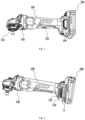
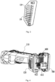
- the power tool is a handheld electric angle grinder including a main body 100 and a battery pack 200 which is detachably coupled to the main body 100.
- the main body 100 in the embodiment of the present application includes a housing 110 and a motor 300, a fan 310, a switch assembly 320, and the like which are disposed in the housing 110.
- the motor 300 drives the fan 310 to rotate and supplies power to an output assembly 330.
- the housing 110 is provided with an air inlet 120 and an air outlet 140.
- the fan 310 is used for generating an airflow and discharging the airflow out of the housing 110 of the tool.
- the fan 310 is disposed coaxially with the shaft of the motor 300 and rotates with the rotation of the motor 300.
- the angle grinder in this embodiment further has a detachable filter screen 160 disposed outside the air inlet 120 to prevent the entry of external dust.
- the output assembly 330 includes an output shaft and a tool accessory mating with the output shaft.
- the tool accessory in this embodiment includes a grinding disc (not shown in the figure).
- an electronic control assembly 400 disposed in the housing 110 is further included in this embodiment, where the housing 110 includes a left housing and a right housing, the electronic control assembly 400 is clamped between stopper ribs of the left housing and the right housing, and the left housing and the right housing are fixed integrally by screws after they are engaged with each other.
- the electronic control assembly 400 in this embodiment is configured to connect the battery pack 200 and the electronic control assembly 400 is also electrically connected to the switch assembly 320 and the motor 300 separately through wires 530.
- the switch assembly 320 controls the motor 300 to be on or off so as to control a working state of the whole power tool.
- the housing 110 in this embodiment includes a front end portion, a handheld portion, and a rear end portion.
- the motor 300, the fan 310, and the switch assembly 320 are disposed in the handheld portion, the output assembly 330 is disposed at the front end portion, and the electronic control assembly 400 is disposed in the rear end portion, where the rear end portion is an battery mounting portion where the angle grinder is connected to the battery pack 200.
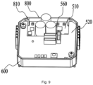
- the electronic control assembly 400 in this embodiment includes an electronic control unit 500, a mounting base 600, a connecting unit 700, and a blocking unit 800.
- the connecting unit 700 conductively connects the battery pack 200 to the electronic control unit 500.
- the mounting base 600 is provided with a mounting portion.
- the connecting unit 700 mates with and is connected to the mounting base 600 via the mounting portion to form a mounting space in which the electronic control unit 500 is mounted.
- the electronic control unit 500 includes a power circuit board 510 and a control circuit board 520, where the control circuit board 520 outputs control instructions to control the operation of the motor 300, and the power circuit board 510 and the control circuit board 520 are electrically connected to each other.
- the electronic control assembly 400 may also include only one circuit board, that is, the power circuit board and the control circuit board are combined into one circuit board.
- the power circuit board 510 is provided with, for example, field-effect transistors 511 (metal-oxide-semiconductor (MOS) field-effect transistors) and capacitors 512, where the field-effect transistors 511 are configured to control a power supply and the motor 300 to be on or off according to control signals, and the capacitors 512 are disposed adjacent to the field-effect transistors 511 and integrated on the power circuit board 510 together with the field-effect transistors 511.
- the capacitors 512 are adjacent to the field-effect transistors 511 and disposed on the same circuit board as the field-effect transistors 511 so that the filtering performance of the capacitors 512 is improved.
- a microcontroller such as a single-chip microcomputer is disposed on the control circuit board 520 and configured to detect and control an on/off state, a temperature, a current, and the like, so as to implement the control of the on/off state, over-temperature protection, and over-current protection.
- the power circuit board 510 in this embodiment is disposed adjacent to or abuts against the mounting base 600.
- the power circuit board 510 is an aluminum substrate.
- a printed circuit is formed and electronic elements are mounted on one surface of the aluminum substrate.
- the other surface of the aluminum substrate is a non-working surface.
- the non-working surface and the mounting base 600 are mounted on a baseplate 610 and in contact with the baseplate 610. Since the mounting base 600 and the power circuit board 510 are both made of aluminum with good thermal conductivity, heat generated by the field-effect transistors 511 on the power circuit board 510 can be transferred and dissipated in time, thereby improving the heat dissipation efficiency of the electronic control unit 500.
- the control circuit board 520 and the power circuit board 510 in this embodiment are stacked within the mounting base 600.
- the control circuit board 520 and the power circuit board 510 are pluggably connected to each other via electrical connectors, where an electrical connector is a small-sized board-to-board connector 570 in which small-sized pin headers which are conductively connected are disposed.
- an electrical connector is a small-sized board-to-board connector 570 in which small-sized pin headers which are conductively connected are disposed.
- a socket is disposed on one of the circuit boards, and a plug mating with and connected to the socket is disposed on the other circuit board so that the power circuit board 510 and the control circuit board 520 can be stacked.
- the combined height of the small-sized board-to-board connectors 570 after insertion does not exceed 4 mm. Since the combined height is relatively small, the height of wall plates 620 of the mounting base 600 can be reduced on the basis that the requirements for adhesive filling and sealing are met, thereby reducing the height
- At least two spacer columns 550 are further directly disposed between the control circuit board 520 and the power circuit board 510.
- the spacer columns 550 are mounted on the control circuit board 520 and configured to ensure a predetermined distance between the control circuit board 520 and the power circuit board 510, thereby avoiding the case where the control circuit board 520 exerts acting forces on electrical elements on the surface of the power circuit board 510, resulting in the failure and damage of the electrical elements.
- the power circuit board is independently disposed and immediately adjacent to the mounting base, thereby ensuring the timely heat dissipation of the power circuit board.
- the control circuit board and the power circuit board are separately stacked on the mounting base, thereby reducing the size of board bodies and a bottom wall of the mounting base.
- the size of the mounting base is reduced, thereby facilitating the reduction of the size of the whole power tool.
- the electronic control assembly 400 can be mounted at the extending leg position without increasing the size of the extending leg of the whole power tool.
- the electronic control assembly is mounted in a grip handle of the housing and the size of the electronic control assembly is reduced, the size of the grip handle of the whole power tool can be reduced, which is more convenient for an user to grip and provides better user experience.
- the control circuit board 520 is directly inserted into and fixed onto the power circuit board 510, which is simple to operate, has a relatively low difficulty, and omits complicated processes such as wire soldering. Since the reliability of the connection through soldering is relatively low, the insertion through the board-to-board connectors 570 improves the reliability of the connection. In addition, the board-to-board connectors 570 are convenient to assemble, thereby facilitating the improvement of the capacity of a production line.
- the power circuit board and the control circuit board in this embodiment may be connected to each other in other manners such as wires provided that the power circuit board and the control circuit board are conductively connected to each other.
- a capacitor circuit board 560 stacked on the power circuit board 510 is further provided in this embodiment, and a projection of the capacitor circuit board 560 and a projection of the control circuit board 520 on the surface of the power circuit board 510 do not overlap each other.
- three capacitors 512 are soldered in parallel onto the capacitor circuit board, and then the capacitor circuit board 560 is soldered to the power circuit board 510.
- the capacitor circuit board 560 is provided with insertion holes and the power circuit board 510 is provided with copper support columns 514.
- the three capacitors are fixed onto the capacitor circuit board through patch soldering, then the insertion holes on the capacitor circuit board are sleeved on the support columns on the power circuit board 510, and finally, the support columns on the power circuit board 510 are fixed through soldering.
- the capacitor circuit board is disposed, and the three capacitors are not directly mounted on the power circuit board 510 but soldered and fixed to the power circuit board 510 by means of the capacitor circuit board, thereby effectively reducing the size of the power circuit board, reducing the size of the mounting base, and facilitating the reduction of the size of the whole power tool, for example, the reduction of the size of the extending leg.
- the number of capacitors is not limited to three and may be set according to specific requirements.
- the capacitor circuit board may also be soldered onto the control circuit board 520 through the patch soldering.
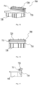
- the mounting base 600 in this embodiment dissipates heat from at least the power circuit board 510.
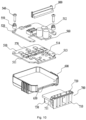
- the mounting base 600 includes the baseplate 610 and the wall plates 620.
- the wall plates 620 are disposed along an edge of the baseplate 610 and provided with an opening 630.
- the opening 630 forms the preceding mounting portion.
- the connecting unit 700 is connected to the mounting base 600 via the opening 630.
- the mounting base 600 is provided with the opening 630, and the connecting unit 700 is inserted to the mounting base via the opening 630.
- the structure is simple and easy to assemble, and the assembly process flow is simplified on the basis that an integration degree is improved.
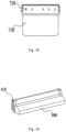
- the mounting base 600 in this embodiment further includes heat dissipation fins 611 and flow guiding fins 621. As shown in FIG. 14 , the heat dissipation fins 611 are disposed on a side of the baseplate 610 facing away from the electronic control unit 500, and heat dissipation channels 612 are formed between the heat dissipation fins 611.
- part of the heat dissipation fins 611 extend onto the wall plates 620 to form the flow guiding fins 621.
- Flow guiding channels 622 are formed between the flow guiding fins 621.
- the flow guiding channels 622 communicate with the heat dissipation channels 612.
- An external airflow enters the flow guiding channels 622 through the air inlet 120 on the housing 110 of the main body and then enters the heat dissipation channels 612 through the flow guiding channels.
- the heat dissipation fins 611 and the flow guiding fins 621 in this embodiment are all ribs protruding from the mounting base 600.
- the mounting base 600 in this embodiment is made of aluminum, and the heat dissipation fins 611 and the flow guiding fins 621 are integrally formed with the mounting base 600.
- the heat dissipation fins are disposed on the baseplate which is in contact with the power circuit board so that the heat dissipation channels are formed, thereby improving the heat dissipation effect and the heat dissipation efficiency and implementing the effective heat dissipation of power elements.
- the flow guiding fins and the flow guiding channels are disposed so that the external airflow can be smoothly guided into the tool in a timely and effective manner, thereby increasing the circulation speed of the airflow on the back of the mounting base, improving the heat dissipation effect, and ensuring the electrical performance of the circuit.
- all the heat dissipation fins 611 may be configured to extend onto adjacent wall plates 620 to form the flow guiding fins 621.
- the heat dissipation fins 611 and the flow guiding fins 621 independent of each other may be disposed on the baseplate 610 and the wall plates 620, respectively provided that the flow guiding channels formed by the flow guiding fins are separately docked with the air inlet and the heat dissipation channels.
- the flow guiding channels 622 guide the external airflow into the housing 110 and also carry away the heat on the wall plates 620 at the same time so that the flow guiding channels 622 also dissipate heat.
- curved transition sections exist at the positions where the direction of the heat dissipation fins 611 and the direction of the flow guiding fins 621 change, so as to facilitate the smooth flow of the airflow.
- the direction of the outlet of the heat dissipation channels 612 may be set along the direction of the flow path of a heat dissipation airflow in the housing 110, so as to guide the airflow in the heat dissipation channels 612 to smoothly move along the flow path of the heat dissipation airflow in the main body 100, thereby avoiding the case where the circulation of the heat dissipation airflow in the whole power tool is affected due to different directions.
- guiding ribs 130 are disposed at the air inlet 120 in this embodiment, where the flow guiding fins 621 and the guiding ribs 130 in this embodiment are correspondingly disposed so that the air inlet 120 is docked with the flow guiding channels622.
- external air can directly enter the flow guiding channels 622 via the air inlet 120 and quickly enters the heat dissipation channels 612 through the flow guiding channels 622 so as to facilitate the rapid and smooth circulation of a cooling airflow in the housing 110 of the whole power tool, thereby quickly removing the heat generated on the power circuit board 510 and improving the heat dissipation efficiency.
- the connecting unit 700 in this embodiment includes a conduction member and a connection base 710.
- the conduction member is disposed on the connection base 710.
- the connection base 710 is inserted to the baseplate 610 of the mounting base 600 via the opening 630.
- connection base 710 is inserted to the mounting base 600 along a direction parallel to a surface of the baseplate 610, where the baseplate 610 is inserted into the engaging groove 711.
- the connection base 710 mates with and is connected to the mounting base 600 to form the mounting space for the power circuit board 510 and the control circuit board 520.
- the conduction member in this embodiment conductively connects the battery pack 200 to the electronic control unit 500, where the conduction member includes an electronic control conduction member and a power supply conduction member, which are conductively connected to each other.
- the electronic control conduction member includes conductive terminals 720 disposed at one end of the connection base 710 and exposed outside the connection base 710.
- the conductive terminals 720 are configured to be conductively connected to the electronic control unit 500.
- the power supply conduction member includes conductive insertion pieces 730 disposed at the other end of the connection base 710 and exposed outside the connection base 710.
- the conductive insertion pieces 730 are configured to be conductively connected to connection terminals of the battery pack 200. Referring to FIG. 11 , after the connection base 710 is assembled to the baseplate 610 of the mounting base 600, the conductive terminals 720 and the conductive insertion pieces 730 are respectively disposed on two sides of the baseplate 610.
- the battery pack is plugged along the guiding ribs of the main body and conductively connected to the conductive terminals 720.
- the conductive insertion pieces 730 of the electronic control assembly 400 in this embodiment need to be inserted to the battery pack. Therefore, the control circuit board 520, the power circuit board 510, and the baseplate 610 of the mounting base 600 in this embodiment are substantially parallel to the direction in which the battery pack is plugged or unplugged.
- the rear end portion of the housing 110 includes a plugging/unplugging surface which pluggably mates with the battery pack 200, and the power circuit board 510, the control circuit board 520, and the baseplate 610 of the mounting base 600 are disposed parallel to the plugging/unplugging surface. Since the preceding configurations in the present application reduce the size of the power circuit board 510, the electronic control assembly 400 can be mounted at the extending leg position without increasing the size of the extending leg of the whole power tool.
- the power circuit board 510 in this embodiment is further provided with a conductive limiting member which conductively mates with the conductive terminals 720 and limits the power circuit board 510.
- the conductive limiting member includes connection holes 513 disposed on the power circuit board 510, where the power circuit board 510 is docked with the conductive terminals 720 through the connection holes 513 and then is fixed and conductively connected to the conductive terminals 720 through soldering.
- the conductive terminals 720 penetrate into the power circuit board 510 along an axial direction of the conductive terminals 720 and then the power circuit board 510 is fixed onto the baseplate 610 of the mounting base 600 through screws 540.
- Two screws 540 sequentially penetrate through the control circuit board, the spacer columns 550, and the power circuit board 510 and then are fixed to the mounting base 600. Since the preceding connection holes 513 are disposed, the power circuit board 510 is automatically guided and positioned during mounting, thereby simplifying the assembly operation flow of the power circuit board 510 and improving the capacity of the production line.
- the electronic control assembly 400 in this embodiment further includes the blocking unit 800 which is connected to the wall plates 620 so as to block the opening 630.
- the blocking unit 800 is assembled to the mounting base 600, one end portion of the blocking unit 800 abuts against the power circuit board 510 and the connection base 710, and the other end portion of the blocking unit 800 is substantially flush with end portions of wall plates 620 on two sides of the blocking unit 800.
- an inner wall of the blocking unit 800, the wall plates of the mounting base 600, and the surface of the electronic control unit enclose and form an adhesive filling cavity 900.
- sliding grooves 810 are respectively disposed on the two sides of the blocking unit 800, and the blocking unit 800 is slidably inserted to the wall plates 620 on two sides of the opening 630.
- the blocking unit 800 is inserted along a direction parallel to the wall plates 620 and finally abuts against the surface of the power circuit board 510.
- an adhesive is injected for electronic elements in the adhesive filling cavity 900 to form a sealant layer 910.
- the sealant layer 910 encapsulates exposed conductive pins of the elements, thereby sealing the electronic elements.
- a sealant is an epoxy resin so as to implement the water resistance, dust resistance, anti-corrosion, sealing, and heat conduction of electrical elements, thereby ensuring the mechanical strength of the whole power tool and avoiding the degradation of the electrical performance.
- the sliding grooves slidably connected to the wall plates are disposed on the blocking unit so that the blocking unit is slidably connected to the wall plates.
- the blocking unit is simple to connect and easy to assemble, thereby simplifying an assembly process.
- a displacement compensation unit 150 is further disposed on an inner wall of the rear end portion of the housing 110, where the displacement compensation unit 150 is disposed at a position where the inner wall of the housing 110 is in contact with the electronic control assembly 400.
- the displacement compensation unit 150 may be an elastic washer or an elastic gasket.
- the elastic displacement compensation unit 150 is disposed so that the electronic control assembly 400 can be elastically in contact with the inner wall of the housing 110, so as to avoid the case where the conductive insertion pieces 730 move with respect to an interface of the battery pack 200 due to vibration during the use of the tool, resulting in the poor contact between the conductive insertion pieces 730 and the battery pack 200 or a damaged interface.
- the electronic control assembly 400 can make small displacement compensation through the displacement compensation unit 150 so as to prevent a relatively large movement of the conductive insertion pieces 730 with respect to the interface of the battery pack 200, thereby prolonging the service life of the tool and improving user experience.
- the electronic control assembly in this embodiment is also applicable to other handheld power tools whose working current is 20 A to 45 A and whose maximum allowable working current is about 65 A, such as electric drills, screwdrivers, sanders, wrenches, polishers, gun drills, electric hammers, and electric picks.
- the connecting unit, the electronic control unit, and the mounting base are integrated into a whole so that the electronic control assembly can not only implement the connection between the main body and the power supply but also implement the heat dissipation of the electronic control unit, which integrates the electricity conduction for the power supply, control, and heat dissipation, thereby improving the integration degree, reducing the occupied space, and facilitating the reduction of the size of the whole power tool.
- the electronic control assembly has relatively great versatility and relatively high adaptability so that it is applicable to other similar tools.
- the conductive terminals 720 of the connecting unit are inserted, and the power circuit board 510 is fixed onto the baseplate 610 of the mounting base, where the power circuit board 510 is mounted onto the mounting base 600 along the direction perpendicular to the baseplate 610 of the mounting base and the power circuit board 510 is fixedly connected to the baseplate 610 through the screws 540 after it is mounted in place.
- the control circuit board 520 of the electronic control unit is conductively connected to the power circuit board 510.
- the plug of the control circuit board 520 is inserted into the socket of the power circuit board 510, or the plug of the power circuit board 510 is inserted into the socket of the control circuit board 520.
- the adhesive is injected into the adhesive filling cavity which is enclosed and formed by the blocking unit 800 and the mounting base 600 so that the sealant layer 910 is formed.
- the electronic control assembly 400 is assembled, the electronic control assembly 400 is mounted into the housing of the main body 100 through the steps below.
- a predetermined number of displacement compensation units 150 are preset at the position where the inner wall of the housing 110 is in contact with the electronic control assembly 400.
- elastic washers or elastic gaskets are clamped into preset engaging grooves.
- the electronic control assembly 400 is mounted in the left housing or the right housing and fixed by the stopper ribs on the inner wall of the housing, and extending wires on the electronic control assembly 400 are fixedly connected to the switch assembly 320 or the motor 300.
- the manners of mounting other structural members in the main body 100 reference may be made to the related art and details are not repeated here.
- the other housing and the preceding housing are engaged with each other and fixed and locked through screws.
- the mounting base is provided with the opening through which the connecting unit is allowed to be inserted so that the connecting unit and the mounting base are assembled through simple insertion.
- the conductive terminals penetrate into the power circuit board and the power circuit board is fixed to the mounting base. Since the conductive terminals on the connecting unit guide and limit the power circuit board during its assembly, the assembly difficulty of the power circuit board is reduced, and the convenience and accuracy of operating the power circuit board are increased. Finally, assembly efficiency and the capacity are improved.
Landscapes
- Engineering & Computer Science (AREA)
- Power Engineering (AREA)
- Mechanical Engineering (AREA)
- Microelectronics & Electronic Packaging (AREA)
- Cooling Or The Like Of Electrical Apparatus (AREA)
Claims (11)
- Elektrowerkzeug, umfassend:einen Hauptkörper (100), der ein Gehäuse (110) und einen Motor (300), eine Schalterbaugruppe (320) und eine elektronische Steuereinrichtung (400) umfasst, die in dem Gehäuse montiert sind, wobei die elektronische Steuerbaugruppe elektrisch mit der Schalterbaugruppe und dem Motor getrennt verbunden ist; undeinen Batteriesatz (200), der abnehmbar mit dem Hauptkörper verbunden ist und einen Verbindungszustand aufweist, bei dem der Batteriesatz mit der elektronischen Steuereinrichtung elektrisch leitend ist, und einen getrennten Zustand, bei dem der Batteriesatz von der elektronischen Steuereinrichtung getrennt ist;wobei die elektronische Steuereinrichtung umfasst:eine elektronische Steuereinheit (500), die eine Leistungsplatine (510) umfasst, die aus einem Metallsubstrat hergestellt ist;einen Montagesockel (600), wobei die Leistungsplatine in Kontakt mit dem Montagesockel ist, der eine Metallbasis ist und mit einer Öffnung (630) versehen ist; undeine Verbindungseinheit (700) zum leitfähigen Verbinden des Batteriesatzes mit der elektronischen Steuereinheit, die über die Öffnung mit dem Montagesockel verbunden ist und an den Montagesockel angepasst ist, um einen Montageraum zu bilden, in dem die elektronische Steuereinheit montiert ist;dadurch gekennzeichnet, dassdie elektronische Steuereinheit ferner eine Steuerplatine (520) umfasst und die Steuerplatine und die Leistungsplatine innerhalb des Montagesockels übereinander angeordnet sind.
- Elektrowerkzeug nach Anspruch 1, wobei der Montagesockel eine Grundplatte (610) und Wandplatten (620) umfasst; und die Wandplatten entlang einer Kante der Grundplatte angeordnet und mit der Öffnung versehen sind.
- Elektrowerkzeug nach Anspruch 1, wobei die Verbindungseinheit einen Verbindungssockel (710) und ein auf dem Verbindungssockel angeordnetes Leitungselement umfasst;
der Verbindungssockel ist über die Öffnung steckbar mit der Grundplatte verbunden; und das Leitungselement ist so ausgelegt, dass es die elektronische Steuereinheit mit dem Batteriesatz verbindet. - Elektrowerkzeug nach Anspruch 3, wobei das Leitungselement ein elektronisches Steuerleitungselement (720) und ein Stromversorgungsleitungselement (730) umfasst, die leitend miteinander verbunden sind; und ein leitendes Begrenzungselement (513) ist auf der Leistungsplatine angeordnet, und das leitende Begrenzungselement ist leitend mit dem elektronischen Steuerleitungselement verbunden und begrenzt die Leistungsplatine.
- Elektrowerkzeug nach Anspruch 2, wobei die elektronische Steuereinrichtung außerdem eine Blockiereinheit (800) umfasst, die mit den Wandplatten verbunden ist, um die Öffnung zu verschließen, und die Blockiereinheit ist mit Gleitnuten (810) versehen, die gleitend mit Wandplatten auf zwei Seiten der Öffnung verbunden sind.
- Elektrowerkzeug nach Anspruch 1, wobei der Montagesockel ferner Wärmeableitungsrippen (611) umfasst, die auf einer von der elektronischen Steuereinheit abgewandten Seite der Grundplatte angeordnet sind, und wobei Wärmeableitungskanäle (612) zwischen den Wärmeableitungsrippen ausgebildet sind.
- Elektrowerkzeug nach Anspruch 6, wobei sich einige Wärmeableitungsrippen oder alle auf die Wandplatten erstrecken, um Strömungsleitrippen (621) zu bilden, zwischen den Strömungsleitrippen sind Strömungsleitkanäle (622) angeordnet, und die Strömungsleitkanäle stehen mit den Wärmeableitungskanälen in Verbindung.
- Elektrowerkzeug nach Anspruch 7, wobei das Gehäuse mit einem Lufteinlass (120) und einem Luftauslass (140) versehen ist und die Strömungsleitkanäle auf dem Montagesockel an den Lufteinlass angedockt sind.
- Elektrowerkzeug nach Anspruch 1, ferner mit einer Verschiebungskompensationseinheit (150), die zwischen einer Innenwand des Gehäuses und der elektronischen Steuereinrichtung angeordnet ist.
- Elektrowerkzeug nach Anspruch 1, wobei die elektronische Steuereinheit ferner eine Steuerplatine (520) aufweist und die Steuerplatine und die Leistungsplatine über elektrische Verbinder steckbar miteinander verbunden sind.
- Elektrowerkzeug nach Anspruch 1, wobei die elektronische Steuereinrichtung an einem Batteriemontageabschnitt angeordnet ist, an dem das Elektrowerkzeug mit dem Batteriesatz verbunden ist.
Applications Claiming Priority (2)
| Application Number | Priority Date | Filing Date | Title |
|---|---|---|---|
| CN201911394525 | 2019-12-30 | ||
| PCT/CN2020/077756 WO2021134905A1 (zh) | 2019-12-30 | 2020-03-04 | 电动工具及其电控组件 |
Publications (3)
| Publication Number | Publication Date |
|---|---|
| EP4046754A1 EP4046754A1 (de) | 2022-08-24 |
| EP4046754A4 EP4046754A4 (de) | 2023-01-25 |
| EP4046754B1 true EP4046754B1 (de) | 2024-03-27 |
Family
ID=76686354
Family Applications (1)
| Application Number | Title | Priority Date | Filing Date |
|---|---|---|---|
| EP20910134.4A Active EP4046754B1 (de) | 2019-12-30 | 2020-03-04 | Elektrowerkzeug und elektrische steuerungsanordnung dafür |
Country Status (3)
| Country | Link |
|---|---|
| US (1) | US12255499B2 (de) |
| EP (1) | EP4046754B1 (de) |
| WO (1) | WO2021134905A1 (de) |
Families Citing this family (6)
| Publication number | Priority date | Publication date | Assignee | Title |
|---|---|---|---|---|
| WO2021134905A1 (zh) * | 2019-12-30 | 2021-07-08 | 南京德朔实业有限公司 | 电动工具及其电控组件 |
| JP7642383B2 (ja) * | 2021-01-22 | 2025-03-10 | 株式会社マキタ | 回転工具 |
| US12157217B2 (en) * | 2021-03-15 | 2024-12-03 | Milwaukee Electric Tool Corporation | Potting boat heat sink |
| US20230026934A1 (en) * | 2021-07-26 | 2023-01-26 | Makita Corporation | Striking tool |
| JP2023176759A (ja) * | 2022-05-31 | 2023-12-13 | 工機ホールディングス株式会社 | 作業機 |
| CN119768098A (zh) * | 2022-12-15 | 2025-04-04 | 三星电子株式会社 | 具有散热结构的清洁器 |
Family Cites Families (19)
| Publication number | Priority date | Publication date | Assignee | Title |
|---|---|---|---|---|
| US7443137B2 (en) * | 2000-08-11 | 2008-10-28 | Milwaukee Electric Tool Corporation | Adapter for a power tool battery |
| JP2006325395A (ja) * | 2005-05-17 | 2006-11-30 | Milwaukee Electric Tool Corp | 動力工具、バッテリ、充電器、およびそれらを動作させる方法 |
| JP5086835B2 (ja) * | 2008-02-20 | 2012-11-28 | パナソニック株式会社 | 電動工具 |
| CN101758488B (zh) * | 2008-10-30 | 2012-07-04 | 苏州宝时得电动工具有限公司 | 电动工具以及电动工具和电池包的组合 |
| CN101925278B (zh) | 2009-06-16 | 2015-05-20 | 天津市松正电动汽车技术股份有限公司 | 电动车控制器 |
| JP5796741B2 (ja) * | 2011-05-19 | 2015-10-21 | 日立工機株式会社 | 電動工具 |
| EP2735078B1 (de) * | 2011-07-24 | 2017-10-04 | Makita Corporation | Elektrowerkzeugsystem und adapter dafür |
| US9450471B2 (en) * | 2012-05-24 | 2016-09-20 | Milwaukee Electric Tool Corporation | Brushless DC motor power tool with combined PCB design |
| CN203896633U (zh) | 2014-06-06 | 2014-10-22 | 上海艾铭思汽车控制系统有限公司 | 一种汽车发动机国四ecu壳体 |
| CN205320371U (zh) | 2015-12-28 | 2016-06-15 | 广东高标电子科技有限公司 | 电容连接结构以及电动车控制器 |
| CN106926096B (zh) | 2015-12-31 | 2020-01-31 | 南京德朔实业有限公司 | 角磨机 |
| JP6724563B2 (ja) * | 2016-05-30 | 2020-07-15 | マックス株式会社 | 工具 |
| CN205690117U (zh) | 2016-06-06 | 2016-11-16 | 深圳亚锐光电科技有限公司 | Led灯具 |
| CN206149617U (zh) | 2016-07-29 | 2017-05-03 | 罗伯特·博世有限公司 | 电子控制单元 |
| CN206632411U (zh) * | 2017-03-23 | 2017-11-14 | 博世电动工具(中国)有限公司 | 电动工具及其电路板组件 |
| TWI676348B (zh) * | 2018-05-25 | 2019-11-01 | 車王電子股份有限公司 | 電動工具 |
| CN113168979B (zh) * | 2018-12-12 | 2024-01-09 | 阿尔卑斯阿尔派株式会社 | 装置以及开关装置 |
| TWI758581B (zh) * | 2019-01-30 | 2022-03-21 | 車王電子股份有限公司 | 電動工具 |
| WO2021134905A1 (zh) * | 2019-12-30 | 2021-07-08 | 南京德朔实业有限公司 | 电动工具及其电控组件 |
-
2020
- 2020-03-04 WO PCT/CN2020/077756 patent/WO2021134905A1/zh not_active Ceased
- 2020-03-04 EP EP20910134.4A patent/EP4046754B1/de active Active
-
2022
- 2022-05-13 US US17/744,146 patent/US12255499B2/en active Active
Also Published As
| Publication number | Publication date |
|---|---|
| EP4046754A4 (de) | 2023-01-25 |
| WO2021134905A1 (zh) | 2021-07-08 |
| EP4046754A1 (de) | 2022-08-24 |
| US20220271624A1 (en) | 2022-08-25 |
| US12255499B2 (en) | 2025-03-18 |
Similar Documents
| Publication | Publication Date | Title |
|---|---|---|
| EP4046754B1 (de) | Elektrowerkzeug und elektrische steuerungsanordnung dafür | |
| JP2001091174A (ja) | 熱伝達コネクタ | |
| CN101594969A (zh) | 具备无刷电动机的电动工具 | |
| CN107135630B (zh) | 控制器组件 | |
| CN210839636U (zh) | 一种交换机 | |
| ES2913790T3 (es) | Dispositivo para accionamiento de motor | |
| CN113119036B (zh) | 电动工具 | |
| CN214708464U (zh) | 控制器 | |
| CN113162154B (zh) | 一种带有散热功能的充电器 | |
| CN213124802U (zh) | 车用线对板连接器 | |
| CN212044554U (zh) | 电动工具 | |
| CN113119037B (zh) | 电动工具 | |
| KR101413579B1 (ko) | 팬모터 어셈블리 | |
| CN215184686U (zh) | 插座 | |
| CN111463045B (zh) | 一种集成电子开关 | |
| CN222883981U (zh) | 一种功率放大器 | |
| CN216721209U (zh) | 一种集成控制开关及具有其的电动工具 | |
| CN218771743U (zh) | 一种直流电动工具用电源适配器 | |
| CN115361829B (zh) | 电子设备及其装配结构 | |
| EP4057313B1 (de) | Integrierter elektronischer schalter und elektrowerkzeug | |
| CN223912732U (zh) | 一种插座的控制模块 | |
| CN212164079U (zh) | 电动工具 | |
| CN219628204U (zh) | 车辆控制器 | |
| CN217363464U (zh) | 一种汽车用电子油泵电机控制器及汽车电子油泵 | |
| CN221747982U (zh) | 充电器 |
Legal Events
| Date | Code | Title | Description |
|---|---|---|---|
| STAA | Information on the status of an ep patent application or granted ep patent |
Free format text: STATUS: THE INTERNATIONAL PUBLICATION HAS BEEN MADE |
|
| PUAI | Public reference made under article 153(3) epc to a published international application that has entered the european phase |
Free format text: ORIGINAL CODE: 0009012 |
|
| STAA | Information on the status of an ep patent application or granted ep patent |
Free format text: STATUS: REQUEST FOR EXAMINATION WAS MADE |
|
| 17P | Request for examination filed |
Effective date: 20220516 |
|
| AK | Designated contracting states |
Kind code of ref document: A1 Designated state(s): AL AT BE BG CH CY CZ DE DK EE ES FI FR GB GR HR HU IE IS IT LI LT LU LV MC MK MT NL NO PL PT RO RS SE SI SK SM TR |
|
| A4 | Supplementary search report drawn up and despatched |
Effective date: 20230102 |
|
| RIC1 | Information provided on ipc code assigned before grant |
Ipc: B25F 5/02 20060101ALI20221220BHEP Ipc: B25F 5/00 20060101AFI20221220BHEP |
|
| DAV | Request for validation of the european patent (deleted) | ||
| DAX | Request for extension of the european patent (deleted) | ||
| GRAP | Despatch of communication of intention to grant a patent |
Free format text: ORIGINAL CODE: EPIDOSNIGR1 |
|
| STAA | Information on the status of an ep patent application or granted ep patent |
Free format text: STATUS: GRANT OF PATENT IS INTENDED |
|
| RIC1 | Information provided on ipc code assigned before grant |
Ipc: B25F 5/02 20060101ALI20231217BHEP Ipc: B25F 5/00 20060101AFI20231217BHEP |
|
| GRAS | Grant fee paid |
Free format text: ORIGINAL CODE: EPIDOSNIGR3 |
|
| INTG | Intention to grant announced |
Effective date: 20240116 |
|
| GRAA | (expected) grant |
Free format text: ORIGINAL CODE: 0009210 |
|
| STAA | Information on the status of an ep patent application or granted ep patent |
Free format text: STATUS: THE PATENT HAS BEEN GRANTED |
|
| AK | Designated contracting states |
Kind code of ref document: B1 Designated state(s): AL AT BE BG CH CY CZ DE DK EE ES FI FR GB GR HR HU IE IS IT LI LT LU LV MC MK MT NL NO PL PT RO RS SE SI SK SM TR |
|
| REG | Reference to a national code |
Ref country code: GB Ref legal event code: FG4D |
|
| REG | Reference to a national code |
Ref country code: CH Ref legal event code: EP |
|
| REG | Reference to a national code |
Ref country code: DE Ref legal event code: R096 Ref document number: 602020028120 Country of ref document: DE |
|
| REG | Reference to a national code |
Ref country code: IE Ref legal event code: FG4D |
|
| PG25 | Lapsed in a contracting state [announced via postgrant information from national office to epo] |
Ref country code: LT Free format text: LAPSE BECAUSE OF FAILURE TO SUBMIT A TRANSLATION OF THE DESCRIPTION OR TO PAY THE FEE WITHIN THE PRESCRIBED TIME-LIMIT Effective date: 20240327 |
|
| REG | Reference to a national code |
Ref country code: LT Ref legal event code: MG9D |
|
| PG25 | Lapsed in a contracting state [announced via postgrant information from national office to epo] |
Ref country code: GR Free format text: LAPSE BECAUSE OF FAILURE TO SUBMIT A TRANSLATION OF THE DESCRIPTION OR TO PAY THE FEE WITHIN THE PRESCRIBED TIME-LIMIT Effective date: 20240628 |
|
| PG25 | Lapsed in a contracting state [announced via postgrant information from national office to epo] |
Ref country code: RS Free format text: LAPSE BECAUSE OF FAILURE TO SUBMIT A TRANSLATION OF THE DESCRIPTION OR TO PAY THE FEE WITHIN THE PRESCRIBED TIME-LIMIT Effective date: 20240627 Ref country code: HR Free format text: LAPSE BECAUSE OF FAILURE TO SUBMIT A TRANSLATION OF THE DESCRIPTION OR TO PAY THE FEE WITHIN THE PRESCRIBED TIME-LIMIT Effective date: 20240327 |
|
| PG25 | Lapsed in a contracting state [announced via postgrant information from national office to epo] |
Ref country code: RS Free format text: LAPSE BECAUSE OF FAILURE TO SUBMIT A TRANSLATION OF THE DESCRIPTION OR TO PAY THE FEE WITHIN THE PRESCRIBED TIME-LIMIT Effective date: 20240627 Ref country code: NO Free format text: LAPSE BECAUSE OF FAILURE TO SUBMIT A TRANSLATION OF THE DESCRIPTION OR TO PAY THE FEE WITHIN THE PRESCRIBED TIME-LIMIT Effective date: 20240627 Ref country code: LT Free format text: LAPSE BECAUSE OF FAILURE TO SUBMIT A TRANSLATION OF THE DESCRIPTION OR TO PAY THE FEE WITHIN THE PRESCRIBED TIME-LIMIT Effective date: 20240327 Ref country code: HR Free format text: LAPSE BECAUSE OF FAILURE TO SUBMIT A TRANSLATION OF THE DESCRIPTION OR TO PAY THE FEE WITHIN THE PRESCRIBED TIME-LIMIT Effective date: 20240327 Ref country code: GR Free format text: LAPSE BECAUSE OF FAILURE TO SUBMIT A TRANSLATION OF THE DESCRIPTION OR TO PAY THE FEE WITHIN THE PRESCRIBED TIME-LIMIT Effective date: 20240628 Ref country code: FI Free format text: LAPSE BECAUSE OF FAILURE TO SUBMIT A TRANSLATION OF THE DESCRIPTION OR TO PAY THE FEE WITHIN THE PRESCRIBED TIME-LIMIT Effective date: 20240327 Ref country code: BG Free format text: LAPSE BECAUSE OF FAILURE TO SUBMIT A TRANSLATION OF THE DESCRIPTION OR TO PAY THE FEE WITHIN THE PRESCRIBED TIME-LIMIT Effective date: 20240327 |
|
| REG | Reference to a national code |
Ref country code: NL Ref legal event code: MP Effective date: 20240327 |
|
| PG25 | Lapsed in a contracting state [announced via postgrant information from national office to epo] |
Ref country code: SE Free format text: LAPSE BECAUSE OF FAILURE TO SUBMIT A TRANSLATION OF THE DESCRIPTION OR TO PAY THE FEE WITHIN THE PRESCRIBED TIME-LIMIT Effective date: 20240327 Ref country code: LV Free format text: LAPSE BECAUSE OF FAILURE TO SUBMIT A TRANSLATION OF THE DESCRIPTION OR TO PAY THE FEE WITHIN THE PRESCRIBED TIME-LIMIT Effective date: 20240327 |
|
| PG25 | Lapsed in a contracting state [announced via postgrant information from national office to epo] |
Ref country code: NL Free format text: LAPSE BECAUSE OF FAILURE TO SUBMIT A TRANSLATION OF THE DESCRIPTION OR TO PAY THE FEE WITHIN THE PRESCRIBED TIME-LIMIT Effective date: 20240327 |
|
| REG | Reference to a national code |
Ref country code: AT Ref legal event code: MK05 Ref document number: 1669473 Country of ref document: AT Kind code of ref document: T Effective date: 20240327 |
|
| PG25 | Lapsed in a contracting state [announced via postgrant information from national office to epo] |
Ref country code: NL Free format text: LAPSE BECAUSE OF FAILURE TO SUBMIT A TRANSLATION OF THE DESCRIPTION OR TO PAY THE FEE WITHIN THE PRESCRIBED TIME-LIMIT Effective date: 20240327 |
|
| PG25 | Lapsed in a contracting state [announced via postgrant information from national office to epo] |
Ref country code: IS Free format text: LAPSE BECAUSE OF FAILURE TO SUBMIT A TRANSLATION OF THE DESCRIPTION OR TO PAY THE FEE WITHIN THE PRESCRIBED TIME-LIMIT Effective date: 20240727 |
|
| PG25 | Lapsed in a contracting state [announced via postgrant information from national office to epo] |
Ref country code: PT Free format text: LAPSE BECAUSE OF FAILURE TO SUBMIT A TRANSLATION OF THE DESCRIPTION OR TO PAY THE FEE WITHIN THE PRESCRIBED TIME-LIMIT Effective date: 20240729 Ref country code: SM Free format text: LAPSE BECAUSE OF FAILURE TO SUBMIT A TRANSLATION OF THE DESCRIPTION OR TO PAY THE FEE WITHIN THE PRESCRIBED TIME-LIMIT Effective date: 20240327 |
|
| PG25 | Lapsed in a contracting state [announced via postgrant information from national office to epo] |
Ref country code: ES Free format text: LAPSE BECAUSE OF FAILURE TO SUBMIT A TRANSLATION OF THE DESCRIPTION OR TO PAY THE FEE WITHIN THE PRESCRIBED TIME-LIMIT Effective date: 20240327 |
|
| PG25 | Lapsed in a contracting state [announced via postgrant information from national office to epo] |
Ref country code: EE Free format text: LAPSE BECAUSE OF FAILURE TO SUBMIT A TRANSLATION OF THE DESCRIPTION OR TO PAY THE FEE WITHIN THE PRESCRIBED TIME-LIMIT Effective date: 20240327 Ref country code: CZ Free format text: LAPSE BECAUSE OF FAILURE TO SUBMIT A TRANSLATION OF THE DESCRIPTION OR TO PAY THE FEE WITHIN THE PRESCRIBED TIME-LIMIT Effective date: 20240327 |
|
| PG25 | Lapsed in a contracting state [announced via postgrant information from national office to epo] |
Ref country code: AT Free format text: LAPSE BECAUSE OF FAILURE TO SUBMIT A TRANSLATION OF THE DESCRIPTION OR TO PAY THE FEE WITHIN THE PRESCRIBED TIME-LIMIT Effective date: 20240327 |
|
| PG25 | Lapsed in a contracting state [announced via postgrant information from national office to epo] |
Ref country code: PL Free format text: LAPSE BECAUSE OF FAILURE TO SUBMIT A TRANSLATION OF THE DESCRIPTION OR TO PAY THE FEE WITHIN THE PRESCRIBED TIME-LIMIT Effective date: 20240327 |
|
| PG25 | Lapsed in a contracting state [announced via postgrant information from national office to epo] |
Ref country code: SK Free format text: LAPSE BECAUSE OF FAILURE TO SUBMIT A TRANSLATION OF THE DESCRIPTION OR TO PAY THE FEE WITHIN THE PRESCRIBED TIME-LIMIT Effective date: 20240327 |
|
| PG25 | Lapsed in a contracting state [announced via postgrant information from national office to epo] |
Ref country code: SM Free format text: LAPSE BECAUSE OF FAILURE TO SUBMIT A TRANSLATION OF THE DESCRIPTION OR TO PAY THE FEE WITHIN THE PRESCRIBED TIME-LIMIT Effective date: 20240327 Ref country code: SK Free format text: LAPSE BECAUSE OF FAILURE TO SUBMIT A TRANSLATION OF THE DESCRIPTION OR TO PAY THE FEE WITHIN THE PRESCRIBED TIME-LIMIT Effective date: 20240327 Ref country code: RO Free format text: LAPSE BECAUSE OF FAILURE TO SUBMIT A TRANSLATION OF THE DESCRIPTION OR TO PAY THE FEE WITHIN THE PRESCRIBED TIME-LIMIT Effective date: 20240327 Ref country code: PT Free format text: LAPSE BECAUSE OF FAILURE TO SUBMIT A TRANSLATION OF THE DESCRIPTION OR TO PAY THE FEE WITHIN THE PRESCRIBED TIME-LIMIT Effective date: 20240729 Ref country code: PL Free format text: LAPSE BECAUSE OF FAILURE TO SUBMIT A TRANSLATION OF THE DESCRIPTION OR TO PAY THE FEE WITHIN THE PRESCRIBED TIME-LIMIT Effective date: 20240327 Ref country code: IS Free format text: LAPSE BECAUSE OF FAILURE TO SUBMIT A TRANSLATION OF THE DESCRIPTION OR TO PAY THE FEE WITHIN THE PRESCRIBED TIME-LIMIT Effective date: 20240727 Ref country code: ES Free format text: LAPSE BECAUSE OF FAILURE TO SUBMIT A TRANSLATION OF THE DESCRIPTION OR TO PAY THE FEE WITHIN THE PRESCRIBED TIME-LIMIT Effective date: 20240327 Ref country code: EE Free format text: LAPSE BECAUSE OF FAILURE TO SUBMIT A TRANSLATION OF THE DESCRIPTION OR TO PAY THE FEE WITHIN THE PRESCRIBED TIME-LIMIT Effective date: 20240327 Ref country code: CZ Free format text: LAPSE BECAUSE OF FAILURE TO SUBMIT A TRANSLATION OF THE DESCRIPTION OR TO PAY THE FEE WITHIN THE PRESCRIBED TIME-LIMIT Effective date: 20240327 Ref country code: AT Free format text: LAPSE BECAUSE OF FAILURE TO SUBMIT A TRANSLATION OF THE DESCRIPTION OR TO PAY THE FEE WITHIN THE PRESCRIBED TIME-LIMIT Effective date: 20240327 |
|
| PG25 | Lapsed in a contracting state [announced via postgrant information from national office to epo] |
Ref country code: IT Free format text: LAPSE BECAUSE OF FAILURE TO SUBMIT A TRANSLATION OF THE DESCRIPTION OR TO PAY THE FEE WITHIN THE PRESCRIBED TIME-LIMIT Effective date: 20240327 |
|
| PG25 | Lapsed in a contracting state [announced via postgrant information from national office to epo] |
Ref country code: IT Free format text: LAPSE BECAUSE OF FAILURE TO SUBMIT A TRANSLATION OF THE DESCRIPTION OR TO PAY THE FEE WITHIN THE PRESCRIBED TIME-LIMIT Effective date: 20240327 |
|
| REG | Reference to a national code |
Ref country code: DE Ref legal event code: R097 Ref document number: 602020028120 Country of ref document: DE |
|
| PG25 | Lapsed in a contracting state [announced via postgrant information from national office to epo] |
Ref country code: DK Free format text: LAPSE BECAUSE OF FAILURE TO SUBMIT A TRANSLATION OF THE DESCRIPTION OR TO PAY THE FEE WITHIN THE PRESCRIBED TIME-LIMIT Effective date: 20240327 |
|
| PG25 | Lapsed in a contracting state [announced via postgrant information from national office to epo] |
Ref country code: DK Free format text: LAPSE BECAUSE OF FAILURE TO SUBMIT A TRANSLATION OF THE DESCRIPTION OR TO PAY THE FEE WITHIN THE PRESCRIBED TIME-LIMIT Effective date: 20240327 |
|
| PLBE | No opposition filed within time limit |
Free format text: ORIGINAL CODE: 0009261 |
|
| STAA | Information on the status of an ep patent application or granted ep patent |
Free format text: STATUS: NO OPPOSITION FILED WITHIN TIME LIMIT |
|
| 26N | No opposition filed |
Effective date: 20250103 |
|
| PGFP | Annual fee paid to national office [announced via postgrant information from national office to epo] |
Ref country code: DE Payment date: 20250128 Year of fee payment: 6 |
|
| PG25 | Lapsed in a contracting state [announced via postgrant information from national office to epo] |
Ref country code: SI Free format text: LAPSE BECAUSE OF FAILURE TO SUBMIT A TRANSLATION OF THE DESCRIPTION OR TO PAY THE FEE WITHIN THE PRESCRIBED TIME-LIMIT Effective date: 20240327 |
|
| PGFP | Annual fee paid to national office [announced via postgrant information from national office to epo] |
Ref country code: FR Payment date: 20250210 Year of fee payment: 6 |
|
| PGFP | Annual fee paid to national office [announced via postgrant information from national office to epo] |
Ref country code: GB Payment date: 20250123 Year of fee payment: 6 |
|
| PG25 | Lapsed in a contracting state [announced via postgrant information from national office to epo] |
Ref country code: MC Free format text: LAPSE BECAUSE OF FAILURE TO SUBMIT A TRANSLATION OF THE DESCRIPTION OR TO PAY THE FEE WITHIN THE PRESCRIBED TIME-LIMIT Effective date: 20240327 |
|
| REG | Reference to a national code |
Ref country code: CH Ref legal event code: H13 Free format text: ST27 STATUS EVENT CODE: U-0-0-H10-H13 (AS PROVIDED BY THE NATIONAL OFFICE) Effective date: 20251023 |
|
| PG25 | Lapsed in a contracting state [announced via postgrant information from national office to epo] |
Ref country code: LU Free format text: LAPSE BECAUSE OF NON-PAYMENT OF DUE FEES Effective date: 20250304 |
|
| REG | Reference to a national code |
Ref country code: BE Ref legal event code: MM Effective date: 20250331 |
|
| PG25 | Lapsed in a contracting state [announced via postgrant information from national office to epo] |
Ref country code: BE Free format text: LAPSE BECAUSE OF NON-PAYMENT OF DUE FEES Effective date: 20250331 |
|
| PG25 | Lapsed in a contracting state [announced via postgrant information from national office to epo] |
Ref country code: CH Free format text: LAPSE BECAUSE OF NON-PAYMENT OF DUE FEES Effective date: 20250331 |
|
| PG25 | Lapsed in a contracting state [announced via postgrant information from national office to epo] |
Ref country code: IE Free format text: LAPSE BECAUSE OF NON-PAYMENT OF DUE FEES Effective date: 20250304 |