EP4045753B1 - Tür mit magnetischer dichtung - Google Patents
Tür mit magnetischer dichtung Download PDFInfo
- Publication number
- EP4045753B1 EP4045753B1 EP20803916.4A EP20803916A EP4045753B1 EP 4045753 B1 EP4045753 B1 EP 4045753B1 EP 20803916 A EP20803916 A EP 20803916A EP 4045753 B1 EP4045753 B1 EP 4045753B1
- Authority
- EP
- European Patent Office
- Prior art keywords
- magnet
- door
- guillotine
- electromagnet
- seat
- Prior art date
- Legal status (The legal status is an assumption and is not a legal conclusion. Google has not performed a legal analysis and makes no representation as to the accuracy of the status listed.)
- Active
Links
Images


Classifications
-
- E—FIXED CONSTRUCTIONS
- E06—DOORS, WINDOWS, SHUTTERS, OR ROLLER BLINDS IN GENERAL; LADDERS
- E06B—FIXED OR MOVABLE CLOSURES FOR OPENINGS IN BUILDINGS, VEHICLES, FENCES OR LIKE ENCLOSURES IN GENERAL, e.g. DOORS, WINDOWS, BLINDS, GATES
- E06B3/00—Window sashes, door leaves, or like elements for closing wall or like openings; Layout of fixed or moving closures, e.g. windows in wall or like openings; Features of rigidly-mounted outer frames relating to the mounting of wing frames
- E06B3/32—Arrangements of wings characterised by the manner of movement; Arrangements of movable wings in openings; Features of wings or frames relating solely to the manner of movement of the wing
- E06B3/34—Arrangements of wings characterised by the manner of movement; Arrangements of movable wings in openings; Features of wings or frames relating solely to the manner of movement of the wing with only one kind of movement
- E06B3/42—Sliding wings; Details of frames with respect to guiding
- E06B3/46—Horizontally-sliding wings
- E06B3/469—Arrangements at the overlapping vertical edges of the wings that engage when closing
-
- E—FIXED CONSTRUCTIONS
- E06—DOORS, WINDOWS, SHUTTERS, OR ROLLER BLINDS IN GENERAL; LADDERS
- E06B—FIXED OR MOVABLE CLOSURES FOR OPENINGS IN BUILDINGS, VEHICLES, FENCES OR LIKE ENCLOSURES IN GENERAL, e.g. DOORS, WINDOWS, BLINDS, GATES
- E06B7/00—Special arrangements or measures in connection with doors or windows
- E06B7/16—Sealing arrangements on wings or parts co-operating with the wings
- E06B7/18—Sealing arrangements on wings or parts co-operating with the wings by means of movable edgings, e.g. draught sealings additionally used for bolting, e.g. by spring force or with operating lever
- E06B7/20—Sealing arrangements on wings or parts co-operating with the wings by means of movable edgings, e.g. draught sealings additionally used for bolting, e.g. by spring force or with operating lever automatically withdrawn when the wing is opened, e.g. by means of magnetic attraction, a pin or an inclined surface, especially for sills
- E06B7/21—Sealing arrangements on wings or parts co-operating with the wings by means of movable edgings, e.g. draught sealings additionally used for bolting, e.g. by spring force or with operating lever automatically withdrawn when the wing is opened, e.g. by means of magnetic attraction, a pin or an inclined surface, especially for sills with sealing strip movable in plane of wing
-
- E—FIXED CONSTRUCTIONS
- E05—LOCKS; KEYS; WINDOW OR DOOR FITTINGS; SAFES
- E05Y—INDEXING SCHEME ASSOCIATED WITH SUBCLASSES E05D AND E05F, RELATING TO CONSTRUCTION ELEMENTS, ELECTRIC CONTROL, POWER SUPPLY, POWER SIGNAL OR TRANSMISSION, USER INTERFACES, MOUNTING OR COUPLING, DETAILS, ACCESSORIES, AUXILIARY OPERATIONS NOT OTHERWISE PROVIDED FOR, APPLICATION THEREOF
- E05Y2800/00—Details, accessories and auxiliary operations not otherwise provided for
- E05Y2800/67—Materials; Strength alteration thereof
- E05Y2800/672—Glass
Definitions
- the present invention relates to a door having a leaf provided with a seal for the sealing, mainly acoustic sealing, thereof, when closed on the door frame or fixture.
- the present invention relates to doors with leaves having so-called magnetic seals, or in other words, draft-stops (or in German Switzerlandbuch Kunststoff-Stopp) or magnetically-activated seal guillotines.
- the present invention relates to solutions which are adapted to doors with hinged leaves but also in particular to doors with sliding leaves.
- the present invention relates to solutions which are adapted to doors of partition walls of the so-called movable type, i.e. not masonry, but made of metal and glass frames, conventionally for delimiting rooms in offices.
- the known seals or draft-stops are mainly designed to close the small leaf openings, called drafts or unfinished openings, which remain between the door and the abutment element thereof or the floor, so as to limit the passage of air and therefore, for example obtain good thermal insulation.
- the solution described in document JP2005009278 relates to a seal which allows preventing the passage of air currents and humidity through the floor drafts of the door by blocking a space between a surface of the floor and the door.
- the solution proposed relates to a door which cooperates with a perfectly flat floor, i.e. with no difference in level along the extension of the doorstep.
- the seal is activated by a magnet push button which is attracted by the door frame, as the door closes thereon. By activating the push button, the position of first magnets is moved, which results in the positioning of the poles of equal polarity thereof on facing magnets positioned in the seal, repelling the seal and forcing it to descend towards the floor.
- the pair of magnets of the push button is to be strong enough to overcome the magnetic force between two pairs of magnets facing each other and positioned in the door and in the seal, in addition to the force of the horizontal return spring of the push button. Furthermore, the action of the push button has to be greater than the one of return springs of the seal in raised position. Therefore, the force to overcome in leaf opening step, which is added to that of the accompanying closing or soft-close systems usually provided on doors of a given weight such as glass and acoustic ones, results in a significant entity which limits the usability of the door, i.e. the ergonomics of the door itself, and therefore the comfortable use of the door.
- the movable element which induces the sealing, is a profiled magnetic rod made of magnetized material which is not hard, therefore slightly soft.
- the magnetic rod extends over the whole length of the leaf.
- the left half of the magnet - in section with respect to the longitudinal extension of the magnet - directed towards the opening side of the door is the area of the south pole, the right half is the area of the north pole.
- the magnetic rod is received by a groove of a profile of the door leaf so that it is a sliding part and is movable downwards.
- the magnetic rod is associated with a flat magnetic rod, positioned on the floor on the doorstep, which has, in section, an inverse polarization, i.e. the south pole part is on the side of the fixture, the north pole part on the opening side of the leaf.
- the force exerted both in extension and in retraction of the guillotine may be adjusted in a highly accurate manner so that the action of the guillotine is hardly perceivable when opening and closing the door leaf.
- the solution proposed is very compact, i.e. not very bulky, and does not have elastic elements, thus being highly simple to assemble and service.
- the solution proposed allows the plane of the door leaf to be kept very close to the plane defined by the fixture or door frame, thus reducing overall volumes of the door, especially if of the sliding leaf type.
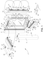
- a door 1 comprises:
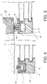
- Said at least one first magnet A always faces said at least one third magnet C so as to perpetually attract said guillotine into said seat 6.
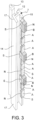
- said seat 6 defines a guillotine extraction and retraction direction or guillotine sliding direction X-X, in which said guillotine sliding direction X-X is arranged transversely to the plane defined by leaf 4 of door 1.
- said seat 6 comprises a seat wall 9 which defines a seat wall bottom portion 16.
- Said guillotine 7 is a "U"-shaped profile 14 having a profile section opening 15, in which said profile 14 is accommodated in said seat 6 with the profile section opening 15 facing said seat wall bottom portion 16.
- said at least one second magnet B is a series of second magnets B placed at least close to longitudinal guillotine ends 17 of said guillotine7.
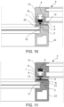
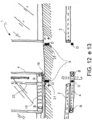
- said door leaf 4 is a door leaf sliding on at least one guide 20 provided on said door frame or door fixture 2 so as to allow the door leaf 4 to slide laterally to said door frame or door fixture 2. Furthermore, at least one sliding foot 18 fixed to the abutment element 3, for example a floor 11, is provided. Said door frame or door fixture 2 comprises a feet seat 19 adapted to accommodate said sliding foot 18 to guide the sliding of said door leaf 4.
- said second magnet interaction element 8 comprises a magnetic slot 21.
- said second magnet interaction element 8 comprises a magnetic slot 21 embedded in said abutment element 2, for example a floor 11.
- said guillotine comprises at least one second magnet B fixed to said guillotine.
- Said door frame or door fixture 2 is placed straddling a length of floor 11.
- Said second magnet interaction element 8 comprises at least one magnetic slot 21 embedded in said floor 11 with polarity arranged inverse with respect to the polarity of the at least one second magnet B.
- Said second magnet B is fixed to said guillotine and interfaced to said at least one magnetic slot 21 only when the door leaf 4 is in closing position of door 1.
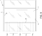
- said door frame or door fixture 2 comprises a side of horizontal frame or crosspiece 24.
- Said second magnet interaction element 8 comprises at least one magnetic slot 21 embedded in said horizontal frame or crosspiece 24 with polarity arranged inverse with respect to the polarity of the at least second magnet B.
- Said second magnet B is fixed to said guillotine and interfaced to said at least one magnetic slot 21 only when the door leaf 4 is in closing position of door 1.
- said second magnet B exerts an action of magnetic attraction which is at least four times greater than the magnetic action exerted by said first magnet A.
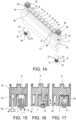
- Each seat accommodates a guillotine 78 made as described above and in particular, housing neodymium magnets.
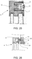
- the double-glass lower horizontal aluminum profile of the leaf edge 10 is shaped, in the lower part - the one oriented towards floor 11 - so as to obtain said seat 6 and contain a second shaped aluminum profile therein which creates the support body of said guillotine.
- Said second aluminum profile is "U"-shaped and contains two series of magnets A, B therein, with the polarity thereof mutually oriented in inverse manner and different force of magnetic attraction or repulsing from each other.
- Third magnets C are arranged on the bottom of the seat and at the first magnets A, the third magnets being oriented so as to attract thereto the first magnets A position in the second "U"-shaped aluminum profile, preferably in the middle part of this profile.
- this has a continuous magnet which is the height of the H-shaped leaf and slides in a seat of the door frame 2 to horizontally slide with a stroke limited by a stop made in the door frame, but sufficient to abut against the leaf when in closed position.
- This magnet creates a magnetic seal and is made of substantially soft magnetic materials.
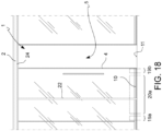
- the leaf edge 10 alternatively has, in the portion abutting against said vertical abutment upright of the door frame, a steel insert which is the width of the thickness of the leaf, or has, in the section of aluminum extrudate thereof, the space for housing a rod or steel strip 23. In closing step of leaf 4, the aforesaid magnetic seal perfectly adheres over the entire length of the edge of the leaf, where the steel strip 23 is provided.
- a housing is formed in the vertical aluminum extrudate of the leaf edge 10, or "back" edge of leaf 4, for the entire height of the profile which creates seat 5 for the guillotine 7, seat 6 which receives a second U-shaped aluminum profile which makes the support body of said guillotine 7, which outer shape is adapted to receive a continuous seal for the entire length thereof.
- Two series of magnets A, B are fixed in the U-shaped profile, the first with magnets A having less force and oriented opposite to the second (second magnets B).
- the present invention relates to a door with sliding leaf comprising one or more of the above-described features.
- the present invention also relates to a door with hinged leaf comprising one or more of the above-described features.
- the present invention also relates to leaves of wardrobes and furnishing containers.
- the main function of the guillotine is the seal against dust, a significant problem for wardrobes and walk-in closets with sliding and/or hinged leaves.
- said first magnet (A) is an electromagnet connected to an electrical activation and deactivation circuit 27, for example, but not necessarily, having a switch 29 controllable by a user to activate said first electromagnet (A). Therefore, a first electromagnet (A) may replace a first magnet (A) described in the preceding description.
- said first electromagnet (A) interacts with a third electromagnet (C) or alternatively with a third magnet (C) or with an element made of material having a high magnetic interaction, e.g. steel, positioned where said third magnet (C) is described in the above description, without departing from the scope of the present invention.
- said second magnet (B) is an electromagnet connected to an electrical activation and deactivation circuit 27, for example, but not necessarily, having a switch 29 which can be controlled by a user to activate said second electromagnet (B). Therefore, a second electromagnet (B) may replace a second magnet (B) described in the preceding description.
- said second electromagnet (A) interacts with a fourth electromagnet (D) or alternatively with a fourth magnet (D) or with an element made of material having a high magnetic interaction, e.g. steel, placed where said fourth magnet (D) is described in the above description, without departing from the scope of the present invention.
- At least one second magnet interaction element (8) is an electromagnet (26), separated by said first magnet or electromagnet (A) and by said second magnet or electromagnet (B), and arranged so as to interact with said second magnet or electromagnet (B) and arranged integral with said abutment element (3) to attract said second magnet or electromagnet (B) to exert an action of extraction on guillotine (7).
- said at least one second magnet interaction element is an electromagnet 26 connected to an electrical activation and deactivation circuit 27, for example, but not necessarily, connected to a control unit 28 and having a switch 29 which can be controlled by a user to activate said at least one second magnet interaction element (8).
- said second magnet interaction element is an electromagnet (8) and comprises a magnetic slot (21), or an electromagnet slot.
- the door may be used, excluding the operation of the guillotines in everyday use and contrarily, activating them remotely also from the workstation or meeting table at the start of a meeting or a private call.
- the electromagnets are connected to a domotics system to be activated and close the guillotines upon the switching from one setting scenario to another.
Landscapes
- Engineering & Computer Science (AREA)
- Civil Engineering (AREA)
- Structural Engineering (AREA)
- Specific Sealing Or Ventilating Devices For Doors And Windows (AREA)
- Rotational Drive Of Disk (AREA)
- Special Wing (AREA)
Claims (14)
- Tür (1), umfassend:- einen Türrahmen oder eine Türhalterung (2), umfassend wenigstens ein Anlageelement (3);- ein Türblatt (4), welches von einer offenen Position, in welcher es eine Öffnung (5) öffnet, welche durch den Türrahmen oder die Türhalterung (2) begrenzt ist, und einer geschlossenen Position bewegbar ist, in welcher es gegen das Anlageelement (3) des Türrahmens oder der Türhalterung (2) anliegt, um die Öffnung (5) zu schließen;- wenigstens einen Fallelement-Sitz oder Sitz (6), welcher in dem Türblatt (4) oder in dem Türrahmen oder der Türhalterung (2) bereitgestellt ist;- wenigstens ein Gleitelement oder Fallelement (7), welches aus einem Material mit schwacher magnetischer Wechselwirkung hergestellt ist; wobei das Fallelement (7) gleitbar in dem Sitz (6) aufgenommen ist, um so von einer zurückgezogenen Position zu einer ausgefahrenen Position und umgekehrt entlang einer Fallelement-Gleitrichtung (X-X) überzugehen;- wenigstens einen ersten Magneten (A) mit Polen (N, S), welche mit der Fallelement-Gleitrichtung (X-X) ausgerichtet oder parallel zu ihr sind;- wobei der erste Magnet oder Elektromagnet (A) integral mit dem Fallelement (7) eingerichtet ist;- wobei der erste Magnet oder Elektromagnet (A) eine magnetische Wirkung einer Anziehung des Fallelements (7) in den Sitz (6) ausübt;- wenigstens einen zweiten Magneten oder Elektromagneten (B), welcher von dem ersten Magneten oder Elektromagneten (A) getrennt ist, mit Polen (N, S), welche mit der Fallelement-Gleitrichtung (X-X) ausgerichtet oder parallel zu ihr sind;- wobei der zweite Magnet oder Elektromagnet (B) integral mit dem Fallelement (7) eingerichtet ist;- wenigstens ein zweites Magnet-Zusammenwirkungselement oder Elektromagnet (8), welches getrennt von dem ersten Magneten oder Elektromagneten (A) und von dem zweiten Magneten oder Elektromagneten (B) und derart eingerichtet ist, dass es mit dem zweiten Magneten oder Elektromagneten (B) zusammenwirkt, und integral mit dem Anlageelement (3) eingerichtet ist, um den zweiten Magneten oder Elektromagneten (B) anzuziehen, um eine Wirkung eines Herausziehens auf das Fallelement (7) auszuüben;- wobei der zweite Magnet oder Elektromagnet (B) derart eingerichtet ist, dass er das Fallelement (7) drückt, um es aus dem Sitz (6) lediglich herauszuziehen, wenn der zweite Magnet oder Elektromagnet (B) im Wesentlichen zu dem zweiten Magnet-Wechselwirkungselement oder Elektromagneten (8) weist oder wenn die Fallelement-Gleitrichtung (X-X) das zweite Magnet-Wechselwirkungselement oder Elektromagnet (8) schneidet;dadurch gekennzeichnet, dass der wenigstens eine erste Magnet oder Elektromagnet (A) eine magnetische Wirkung ausübt, welche global kleiner als die magnetische Wirkung ist, welche global durch den wenigstens einen zweiten Magneten oder Elektromagneten (B) ausgeübt wird.
- Tür (1) nach Anspruch 1, ferner umfassend:- eine Sitzwand (9), welche den Sitz (6) begrenzt;- wenigstens einen dritten Magneten (C), welcher integral mit der Sitzwand (9) eingerichtet ist;- wobei der wenigstens eine erste Magnet (A) stets zu dem wenigstens einen dritten Magneten (C) weist, um so dauerhaft das Fallelement in den Sitz (6) anzuziehen;wobei ferner umfassend:
oder- eine Sitzwand (9), welche den Sitz (6) begrenzt;- wenigstens ein drittes Elektromagnet- oder Magnetfeld-Schließelement (C), welches integral mit der Sitzwand (9) eingerichtet ist;- wobei der wenigstens eine erste Magnet oder Elektromagnet (A) stets zu dem wenigstens einen dritten Elektromagneten oder dem Magnetfeld-Schließelement (C) weist, beispielsweise ein Element, welches aus einem Material mit einer hohen magnetischen Wechselwirkung hergestellt ist, um so das Fallelement in den Sitz (6) anzuziehen;
und/oder wobei- wenigstens ein zweites Mahnet-Wechselwirkungselement (8) ein Elektromagnet (8) ist, getrennt von dem ersten Magneten (A) und von dem zweiten Magneten (B) und derart eingerichtet ist, dass es mit dem zweiten Magneten (B) wechselwirkt und integral mit dem Anlageelement (3) eingerichtet ist, um den zweiten Magneten (B) anzuziehen, um eine Wirkung eines Herausziehens auf das Fallelement (7) auszuüben;- wobei der zweite Magnet (B) derart eingerichtet ist, dass er das Fallelement (7) drückt, um es von dem Sitz (6) lediglich herauszuziehen, wenn der zweite Magnet (B) im Wesentlichen zu dem zweiten Magnet-Wechselwirkungselement (8) angeordnet ist oder wenn die Fallelement-Gleitrichtung (X-X) das zweite Magnet-Wechselwirkungselement (8) schneidet. - Tür (1) nach Anspruch 1 oder 2, wobei:- das Türblatt (4) wenigstens einen Boden-Blattrand (10) umfasst, welcher dazu eingerichtet ist, zu einem Anlageelement (3) zu weisen, wobei das Anlageelement ein Boden (11) ist;- der Sitz (6) in dem Boden-Blattrand (10) bereitgestellt ist;- das Fallelement (7) eine Fallelement-Anlagefläche (12) umfasst, welche zu dem zweiten Magnet-Wechselwirkungselement oder Elektromagneten (8) weisend eingerichtet ist;- die Fallelement-Anlagefläche (12) ein akustische Abdichtung (13) umfasst, welche dazu eingerichtet ist, zwischen dem Fallelement (7) und dem Anlageelement (3) eingefügt zu sein.
- Tür (1) nach einem der vorhergehenden Ansprüche, wobei:- der Sitz (6) eine Fallelement-Auszieh- und Zurückziehrichtung oder Fallelement-Gleitrichtung (X-X) definiert, wobei die Fallelement-Gleitrichtung (X-X) transversal zu der Ebene eingerichtet ist, welche durch das Blatt (4) der Tür (1) definiert ist;
oder wobei:- der Sitz eine Fallelement-Auszieh- und Zurückziehrichtung oder Fallelement-Gleitrichtung (X-X) definiert, wobei die Fallelement-Gleitrichtung (X-X) parallel zu der Ebene eingerichtet ist, welche durch das Blatt (4) der Tür (1) definiert ist. - Tür (1) nach einem der vorhergehenden Ansprüche, wobei:- der Sitz (6) eine Sitzwand (9) umfasst, welche einen Sitzwand-Bodenabschnitt (16) definiert;- das Fallelement (7) ein "U"-förmiges Profil (14) ist, welches eine Profilabschnitt-Öffnung (15) aufweist, wobei das Profil (14) in dem Sitz (6) aufgenommen ist, wobei die Profilabschnitt-Öffnung (15) zu dem Sitzwand-Bodenabschnitt (16) weist.
- Tür (1) nach einem der vorhergehenden Ansprüche, wobei:- der wenigstens eine Magnet oder Elektromagnet (A) eine Reihe von ersten Magneten oder Elektromagneten (A) ist, welche entlang der longitudinalen Erstreckung des Fallelements (7) verteilt sind;
und/oder wobei- der wenigstens eine zweite Magnet oder Elektromagnet (B) eine Reihe von zweiten Magneten oder Elektromagneten (B) ist, welche wenigstes nahe zu longitudinalen Fallelement-Enden (17) des Fallelements (7) platziert ist. - Tür (1) nach einem der vorhergehenden Ansprüche, wobei:- der erste Magnet (A) eine vorbestimmte Polarität (N/S) aufweist;- der zweite Magnet (B) eine vorbestimmte Polarität (N/S) aufweist;- und wobei die Anordnung der Polarität (N/S) des ersten Magneten (A) invers bezüglich der Anordnung der Polarität (S/N) des zweiten Magneten (B) ist, wenn sie in dem Fallelement (7) positioniert sind;
oder wobei:- der erste Magnet (A) ein erster Elektromagnet ist;- der zweite Magnet (B) ein Magnetfeld-Schließelement ist, beispielsweise ein Element, welches aus einem Material hergestellt ist, welches eine hohe magnetische Wechselwirkung aufweist;- und wobei, wenn der erste Elektromagnet (A) aktiviert ist, er eine magnetische Anziehung mit dem Magnetfeld-Schließelement erzeugt, beispielsweise einem Element, welches aus einem Material mit einer hohen magnetischen Wechselwirkung hergestellt ist. - Tür (1) nach einem der vorhergehenden Ansprüche, wobei:- das Türblatt (4) ein Türblatt ist, welches an wenigstens einer Führung (20) gleitet, welche an dem Türrahmen oder der Türhalterung (2) bereitgestellt ist, um so dem Türblatt (4) zu erlauben, lateral zu dem Türrahmen oder der Türhalterung (2) zu gleiten;
und wobei:- wenigstens ein Gleitfuß (18), welcher an dem Anlageelement (3) befestigt ist, wie beispielsweise einem Boden (11), bereitgestellt ist;- der Türrahmen oder die Türhalterung (2) einen Fußsitz (19) umfasst, welcher dazu eingerichtet ist, den wenigstens einen Gleitfuß (18) aufzunehmen, um die Gleitbewegung des Türblatts (4) zu führen. - Tür (1) nach einem der vorhergehenden Ansprüche, wobei:- das zweite magnetische Wechselwirkungselement oder Elektromagnet (8) eine Magnetausnehmung (21) umfasst oder beispielsweise ein Magnetfeld-Schließelement oder einen Elektromagneten;
und/oder wobei- das zweite Magnet-Wechselwirkungselement oder Elektromagnet (8) eine Magnetausnehmung (21) umfasst, welche in dem Anlageelement (2) eingebettet ist, beispielsweise einem Boden (11),
und/oder wobei- das zweite Magnet-Wechselwirkungselement oder Elektromagnet (8) eine Magnetausnehmung (21) umfasst, welche einen Elektromagneten umfasst. - Tür (1) nach einem der vorhergehenden Ansprüche, wobei:- der Türrahmen oder die Türhalterung (2) eine vertikale Rahmenseite (22) umfasst;- das Fallelement wenigstens einen zweiten Magneten oder Elektromagneten (B) umfasst, welcher an dem Fallelement befestigt und lediglich wenn das Türblatt (4) in Schließposition der Tür (1) ist, mit einem zweiten Magnet-Wechselwirkungselement (8) gekoppelt ist, welches einen Streifen umfasst, welcher aus einem Material hergestellt ist, welches eine hohe magnetische Wechselwirkung (23) aufweist, z.B. Stahl.
- Tür (1) nach einem der vorhergehenden Ansprüche, wobei:- das Fallelement wenigstens einen zweiten Magneten oder Elektromagneten (B) umfasst, welcher an dem Fallelement befestigt ist;- der Türrahmen oder die Türhalterung (2) eine Länge des Bodens (11) überspannend platziert ist;- das zweite Magnet-Wechselwirkungselement oder Elektromagnet (8) wenigstens eine Magnetausnehmung (21) oder ein Element umfasst, welches aus einem Material mit einer hohen magnetischen Wechselwirkung hergestellt ist, welches in dem Boden (11) mit einer Polarität eingebettet ist, welche invers bezüglich der Polarität des wenigstens einen zweiten Magneten oder Elektromagneten (B) ist;- der zweite Magnet oder Elektromagnet (B) an dem Fallelement befestigt und mit der wenigstens einen Magnetausnehmung (21) oder dem aus einem Material mit hoher magnetischer Wechselwirkung hergestellten Element lediglich gekoppelt ist, wenn das Türblatt (4) in Schließposition der Tür (1) ist.
- Tür (1) nach einem der vorhergehenden Ansprüche, wobei:- der Türrahmen oder die Türhalterung (2) eine Seite eines horizontalen Rahmens oder eines Querelements (24) umfasst;- das zweite Magnet-Wechselwirkungselement oder der Elektromagnet (8) wenigstens eine Magnetausnehmung (21) oder ein Element umfasst, welches eine hohe magnetische Wechselwirkung aufweist, welches in dem horizontalen Rahmen oder dem Querelement (24) mit einer Polarität eingebettet ist, welche invers bezüglich der Polarität des wenigstens einen zweiten Magneten (B) ist;- der zweite Magnet oder Elektromagnet (B) an dem Fallelement befestigt und lediglich an die wenigstens eine Magnetausnehmung (21) gekoppelt ist, wenn das Türblatt (4) in Schließposition der Tür (1) ist.
- Tür (1) nach einem der vorhergehenden Ansprüche, wobei:- der Türrahmen oder die Türhalterung (2) und das Fallelement (7) aus einem Material hergestellt sind, welches eine niedrige magnetische Wechselwirkung aufweist, wie beispielsweise Aluminium.
- Tür (1) nach einem der vorhergehenden Ansprüche, wobei:- der zweite Magnet oder Elektromagnet (B) eine Wirkung einer magnetischen Anziehung ausübt, welche wenigstens vier Mal größer ist als magnetische Wirkung, die von dem ersten Magneten oder Elektromagneten (A) ausgeübt wird.
Applications Claiming Priority (2)
| Application Number | Priority Date | Filing Date | Title |
|---|---|---|---|
| IT102019000018683A IT201900018683A1 (it) | 2019-10-14 | 2019-10-14 | Porta con guarnizione magnetica |
| PCT/IB2020/059622 WO2021074797A1 (en) | 2019-10-14 | 2020-10-14 | Door with magnetic seal |
Publications (3)
| Publication Number | Publication Date |
|---|---|
| EP4045753A1 EP4045753A1 (de) | 2022-08-24 |
| EP4045753C0 EP4045753C0 (de) | 2023-12-13 |
| EP4045753B1 true EP4045753B1 (de) | 2023-12-13 |
Family
ID=69570760
Family Applications (1)
| Application Number | Title | Priority Date | Filing Date |
|---|---|---|---|
| EP20803916.4A Active EP4045753B1 (de) | 2019-10-14 | 2020-10-14 | Tür mit magnetischer dichtung |
Country Status (8)
| Country | Link |
|---|---|
| US (1) | US12258811B2 (de) |
| EP (1) | EP4045753B1 (de) |
| JP (1) | JP7676373B2 (de) |
| AU (1) | AU2020367544A1 (de) |
| CA (1) | CA3154346A1 (de) |
| IL (1) | IL292201A (de) |
| IT (1) | IT201900018683A1 (de) |
| WO (1) | WO2021074797A1 (de) |
Families Citing this family (3)
| Publication number | Priority date | Publication date | Assignee | Title |
|---|---|---|---|---|
| CN114575728B (zh) * | 2022-03-19 | 2023-06-20 | 江苏千喜智能科技有限公司 | 一种具有快速锁定功能的录音用特种复合隔音门 |
| WO2024247631A1 (ja) * | 2023-05-31 | 2024-12-05 | 株式会社Lixil | 建具 |
| CN118422985B (zh) * | 2024-06-04 | 2024-11-01 | 泰森日盛集团有限公司 | 通风隔音门扇和通风隔音门 |
Family Cites Families (28)
| Publication number | Priority date | Publication date | Assignee | Title |
|---|---|---|---|---|
| FR1363546A (fr) | 1963-06-20 | 1964-06-12 | Dispositif pour la fermeture et l'étanchéification de récipients et en particulier de meubles frigorifiques | |
| US4300314A (en) | 1979-10-22 | 1981-11-17 | Magnetic Weather Stripping Corp. | Threshold with magnetic weather stripping |
| DE3533782A1 (de) | 1985-09-21 | 1987-03-26 | Harry Frey | Tuerdichtung vorzugsweise fuer schwellenlose tueren |
| US4703586A (en) | 1985-10-03 | 1987-11-03 | Derek Smith | Door sealing mechansim |
| DE3708176C1 (en) | 1987-03-13 | 1988-11-10 | Harry Frey | Magnetic door seal |
| US5035085A (en) * | 1989-01-27 | 1991-07-30 | Ardco, Inc. | Refrigerator door assembly with thermal insulated door mounting frame |
| US5039826A (en) * | 1989-11-06 | 1991-08-13 | Newland James F | Seal for shielding enclosure |
| DE4010994C2 (de) | 1990-04-05 | 1995-03-23 | Athmer Fa F | Magnetische Dichtung für einen unteren Türspalt |
| DE4011351A1 (de) | 1990-04-07 | 1991-10-24 | Athmer Fa F | Magnetische tuerdichtung |
| US5161329A (en) * | 1991-12-03 | 1992-11-10 | Brown Noel S | Insulated closure structure |
| DE4214473A1 (de) | 1992-05-06 | 1993-11-11 | Frey Harry | Vorrichtung zum Trennen der Fußbodenbeläge unter einer Tür |
| JPH062470A (ja) * | 1992-06-18 | 1994-01-11 | Daiwa House Ind Co Ltd | 間仕切り扉の隙間風防止構造 |
| DE29600334U1 (de) | 1996-01-10 | 1997-05-07 | Möller, Gerd, 34582 Borken | Magnetische Türdichtung und Zusatzprofile zu deren Herstellung |
| JPH10238249A (ja) * | 1997-02-27 | 1998-09-08 | Matsushita Electric Works Ltd | 扉の隙間防止構造 |
| JP3043428U (ja) * | 1997-05-14 | 1997-11-18 | ニチレイマグネット株式会社 | 戸の隙間閉鎖装置 |
| CA2239746C (en) * | 1998-06-05 | 2002-03-26 | Camco Inc. | French door gasket corner seal |
| JP2000120355A (ja) * | 1998-10-16 | 2000-04-25 | Kazumoto Hashizume | 建 具 |
| JP2005009278A (ja) | 2003-06-19 | 2005-01-13 | Mori Homes:Kk | 建具 |
| US8429929B2 (en) * | 2009-08-24 | 2013-04-30 | Cold Chain, Llc | Flexible door panel cold storage door system |
| DE102010030709B4 (de) * | 2010-06-30 | 2012-05-03 | Geze Gmbh | Schiebetüranlage |
| DE102010030710B4 (de) * | 2010-06-30 | 2024-02-29 | Geze Gmbh | Türanlage |
| CN101852057B (zh) * | 2010-07-08 | 2012-01-11 | 浙江临亚股份有限公司 | 一种门底自动密封装置 |
| US9052135B2 (en) * | 2013-08-21 | 2015-06-09 | True Manufacturing Company, Inc. | Refrigerator cooler with magnetic french door gaskets and method of manufacture |
| JP2016211201A (ja) * | 2015-05-07 | 2016-12-15 | トヨタホーム株式会社 | トイレの通気システム |
| PL3284897T3 (pl) | 2016-08-18 | 2022-08-01 | Athmer Ohg | USZCZELKA Z DAJĄCĄ SlĘ PRZEMIESZCZAĆ LISTWĄ USZCZELNIAJĄCĄ I Z MECHANIZMEM PRZYWRACANIA l/ALBO NADMIERNEGO SKOKU |
| DE102016122265A1 (de) | 2016-11-18 | 2018-05-24 | Athmer Ohg | Magnetische Türspaltdichtung |
| CA3048900A1 (en) | 2017-01-05 | 2018-07-12 | Aurora Systems Inc. | Top-hanging sliding door including bottom guide and seal |
| DE102017127642A1 (de) | 2017-11-23 | 2019-05-23 | Athmer Ohg | Schiebetürdichtungssystem |
-
2019
- 2019-10-14 IT IT102019000018683A patent/IT201900018683A1/it unknown
-
2020
- 2020-10-14 EP EP20803916.4A patent/EP4045753B1/de active Active
- 2020-10-14 JP JP2022522281A patent/JP7676373B2/ja active Active
- 2020-10-14 IL IL292201A patent/IL292201A/en unknown
- 2020-10-14 AU AU2020367544A patent/AU2020367544A1/en active Pending
- 2020-10-14 WO PCT/IB2020/059622 patent/WO2021074797A1/en not_active Ceased
- 2020-10-14 US US17/768,812 patent/US12258811B2/en active Active
- 2020-10-14 CA CA3154346A patent/CA3154346A1/en active Pending
Also Published As
| Publication number | Publication date |
|---|---|
| JP2022551731A (ja) | 2022-12-13 |
| US12258811B2 (en) | 2025-03-25 |
| WO2021074797A1 (en) | 2021-04-22 |
| EP4045753C0 (de) | 2023-12-13 |
| EP4045753A1 (de) | 2022-08-24 |
| IL292201A (en) | 2022-06-01 |
| IT201900018683A1 (it) | 2021-04-14 |
| CA3154346A1 (en) | 2021-04-22 |
| AU2020367544A1 (en) | 2022-05-12 |
| JP7676373B2 (ja) | 2025-05-14 |
| US20240093547A1 (en) | 2024-03-21 |
Similar Documents
| Publication | Publication Date | Title |
|---|---|---|
| EP4045753B1 (de) | Tür mit magnetischer dichtung | |
| US20070194578A1 (en) | Self latching device | |
| JP2014505815A (ja) | レール隠蔽形窓装置 | |
| JP6408466B2 (ja) | ドロップダウンシール及び建物部分 | |
| US7331369B2 (en) | Sliding door magnetic latch | |
| US20160076293A1 (en) | System and device for soft closing | |
| CA2730445A1 (en) | Improvements in relation to doorsills | |
| NL2026142B1 (en) | Shutter panel with an automatic louver closure assembly and related damping features | |
| US3280506A (en) | Flush closing sliding door assembly | |
| US9273511B2 (en) | Shower door assembly with linkage control | |
| KR200302204Y1 (ko) | 출입문의 바닥 및 문틀 틈새 차폐장치 | |
| JP2008285864A (ja) | 扉保持装置 | |
| GB2450001A (en) | Stay with first slider released by release mechanism of second slider in predetermined track position | |
| KR101959987B1 (ko) | 슬라이드식 3도어를 가지는 장롱의 댐핑시스템 | |
| KR20110010955U (ko) | 조립식화장실 구축용 다기능 칸막이설치프레임 | |
| EP1781886B1 (de) | Verbessertes rollmoskitonetz mit faltführungen | |
| JP2006083569A (ja) | 引戸の閉じ支援装置 | |
| JP3194732U (ja) | シャワーヘッドの散水コントロール構造 | |
| CN212562944U (zh) | 一种淋浴房移动门 | |
| KR20100044323A (ko) | 창문시스템 | |
| JP2022045544A (ja) | 引き戸付き開き戸の戸構造 | |
| EP1605121A1 (de) | Notausgangstür | |
| JPS5918812B2 (ja) | オシボタンスイツチノドウサホジヨソウチ | |
| US20060180279A1 (en) | Device for actuating a blind assembly integral to a door window | |
| GB2460687A (en) | Door closing apparatus having touchless means urging door into closed position which is damped by the escaping air |
Legal Events
| Date | Code | Title | Description |
|---|---|---|---|
| STAA | Information on the status of an ep patent application or granted ep patent |
Free format text: STATUS: UNKNOWN |
|
| STAA | Information on the status of an ep patent application or granted ep patent |
Free format text: STATUS: THE INTERNATIONAL PUBLICATION HAS BEEN MADE |
|
| PUAI | Public reference made under article 153(3) epc to a published international application that has entered the european phase |
Free format text: ORIGINAL CODE: 0009012 |
|
| STAA | Information on the status of an ep patent application or granted ep patent |
Free format text: STATUS: REQUEST FOR EXAMINATION WAS MADE |
|
| 17P | Request for examination filed |
Effective date: 20220408 |
|
| AK | Designated contracting states |
Kind code of ref document: A1 Designated state(s): AL AT BE BG CH CY CZ DE DK EE ES FI FR GB GR HR HU IE IS IT LI LT LU LV MC MK MT NL NO PL PT RO RS SE SI SK SM TR |
|
| DAV | Request for validation of the european patent (deleted) | ||
| DAX | Request for extension of the european patent (deleted) | ||
| GRAP | Despatch of communication of intention to grant a patent |
Free format text: ORIGINAL CODE: EPIDOSNIGR1 |
|
| STAA | Information on the status of an ep patent application or granted ep patent |
Free format text: STATUS: GRANT OF PATENT IS INTENDED |
|
| INTG | Intention to grant announced |
Effective date: 20230626 |
|
| GRAS | Grant fee paid |
Free format text: ORIGINAL CODE: EPIDOSNIGR3 |
|
| GRAA | (expected) grant |
Free format text: ORIGINAL CODE: 0009210 |
|
| STAA | Information on the status of an ep patent application or granted ep patent |
Free format text: STATUS: THE PATENT HAS BEEN GRANTED |
|
| AK | Designated contracting states |
Kind code of ref document: B1 Designated state(s): AL AT BE BG CH CY CZ DE DK EE ES FI FR GB GR HR HU IE IS IT LI LT LU LV MC MK MT NL NO PL PT RO RS SE SI SK SM TR |
|
| REG | Reference to a national code |
Ref country code: GB Ref legal event code: FG4D |
|
| REG | Reference to a national code |
Ref country code: CH Ref legal event code: EP |
|
| REG | Reference to a national code |
Ref country code: DE Ref legal event code: R096 Ref document number: 602020022810 Country of ref document: DE |
|
| REG | Reference to a national code |
Ref country code: IE Ref legal event code: FG4D |
|
| U01 | Request for unitary effect filed |
Effective date: 20240108 |
|
| U07 | Unitary effect registered |
Designated state(s): AT BE BG DE DK EE FI FR IT LT LU LV MT NL PT SE SI Effective date: 20240117 |
|
| PG25 | Lapsed in a contracting state [announced via postgrant information from national office to epo] |
Ref country code: GR Free format text: LAPSE BECAUSE OF FAILURE TO SUBMIT A TRANSLATION OF THE DESCRIPTION OR TO PAY THE FEE WITHIN THE PRESCRIBED TIME-LIMIT Effective date: 20240314 |
|
| PG25 | Lapsed in a contracting state [announced via postgrant information from national office to epo] |
Ref country code: ES Free format text: LAPSE BECAUSE OF FAILURE TO SUBMIT A TRANSLATION OF THE DESCRIPTION OR TO PAY THE FEE WITHIN THE PRESCRIBED TIME-LIMIT Effective date: 20231213 |
|
| PG25 | Lapsed in a contracting state [announced via postgrant information from national office to epo] |
Ref country code: GR Free format text: LAPSE BECAUSE OF FAILURE TO SUBMIT A TRANSLATION OF THE DESCRIPTION OR TO PAY THE FEE WITHIN THE PRESCRIBED TIME-LIMIT Effective date: 20240314 Ref country code: ES Free format text: LAPSE BECAUSE OF FAILURE TO SUBMIT A TRANSLATION OF THE DESCRIPTION OR TO PAY THE FEE WITHIN THE PRESCRIBED TIME-LIMIT Effective date: 20231213 |
|
| PG25 | Lapsed in a contracting state [announced via postgrant information from national office to epo] |
Ref country code: RS Free format text: LAPSE BECAUSE OF FAILURE TO SUBMIT A TRANSLATION OF THE DESCRIPTION OR TO PAY THE FEE WITHIN THE PRESCRIBED TIME-LIMIT Effective date: 20231213 Ref country code: NO Free format text: LAPSE BECAUSE OF FAILURE TO SUBMIT A TRANSLATION OF THE DESCRIPTION OR TO PAY THE FEE WITHIN THE PRESCRIBED TIME-LIMIT Effective date: 20240313 Ref country code: HR Free format text: LAPSE BECAUSE OF FAILURE TO SUBMIT A TRANSLATION OF THE DESCRIPTION OR TO PAY THE FEE WITHIN THE PRESCRIBED TIME-LIMIT Effective date: 20231213 |
|
| PG25 | Lapsed in a contracting state [announced via postgrant information from national office to epo] |
Ref country code: IS Free format text: LAPSE BECAUSE OF FAILURE TO SUBMIT A TRANSLATION OF THE DESCRIPTION OR TO PAY THE FEE WITHIN THE PRESCRIBED TIME-LIMIT Effective date: 20240413 |
|
| PG25 | Lapsed in a contracting state [announced via postgrant information from national office to epo] |
Ref country code: CZ Free format text: LAPSE BECAUSE OF FAILURE TO SUBMIT A TRANSLATION OF THE DESCRIPTION OR TO PAY THE FEE WITHIN THE PRESCRIBED TIME-LIMIT Effective date: 20231213 |
|
| PG25 | Lapsed in a contracting state [announced via postgrant information from national office to epo] |
Ref country code: SK Free format text: LAPSE BECAUSE OF FAILURE TO SUBMIT A TRANSLATION OF THE DESCRIPTION OR TO PAY THE FEE WITHIN THE PRESCRIBED TIME-LIMIT Effective date: 20231213 |
|
| PG25 | Lapsed in a contracting state [announced via postgrant information from national office to epo] |
Ref country code: SM Free format text: LAPSE BECAUSE OF FAILURE TO SUBMIT A TRANSLATION OF THE DESCRIPTION OR TO PAY THE FEE WITHIN THE PRESCRIBED TIME-LIMIT Effective date: 20231213 Ref country code: SK Free format text: LAPSE BECAUSE OF FAILURE TO SUBMIT A TRANSLATION OF THE DESCRIPTION OR TO PAY THE FEE WITHIN THE PRESCRIBED TIME-LIMIT Effective date: 20231213 Ref country code: RO Free format text: LAPSE BECAUSE OF FAILURE TO SUBMIT A TRANSLATION OF THE DESCRIPTION OR TO PAY THE FEE WITHIN THE PRESCRIBED TIME-LIMIT Effective date: 20231213 Ref country code: IS Free format text: LAPSE BECAUSE OF FAILURE TO SUBMIT A TRANSLATION OF THE DESCRIPTION OR TO PAY THE FEE WITHIN THE PRESCRIBED TIME-LIMIT Effective date: 20240413 Ref country code: CZ Free format text: LAPSE BECAUSE OF FAILURE TO SUBMIT A TRANSLATION OF THE DESCRIPTION OR TO PAY THE FEE WITHIN THE PRESCRIBED TIME-LIMIT Effective date: 20231213 |
|
| PG25 | Lapsed in a contracting state [announced via postgrant information from national office to epo] |
Ref country code: PL Free format text: LAPSE BECAUSE OF FAILURE TO SUBMIT A TRANSLATION OF THE DESCRIPTION OR TO PAY THE FEE WITHIN THE PRESCRIBED TIME-LIMIT Effective date: 20231213 |
|
| PG25 | Lapsed in a contracting state [announced via postgrant information from national office to epo] |
Ref country code: PL Free format text: LAPSE BECAUSE OF FAILURE TO SUBMIT A TRANSLATION OF THE DESCRIPTION OR TO PAY THE FEE WITHIN THE PRESCRIBED TIME-LIMIT Effective date: 20231213 |
|
| REG | Reference to a national code |
Ref country code: DE Ref legal event code: R097 Ref document number: 602020022810 Country of ref document: DE |
|
| U20 | Renewal fee for the european patent with unitary effect paid |
Year of fee payment: 5 Effective date: 20240827 |
|
| PLBE | No opposition filed within time limit |
Free format text: ORIGINAL CODE: 0009261 |
|
| STAA | Information on the status of an ep patent application or granted ep patent |
Free format text: STATUS: NO OPPOSITION FILED WITHIN TIME LIMIT |
|
| 26N | No opposition filed |
Effective date: 20240916 |
|
| PGFP | Annual fee paid to national office [announced via postgrant information from national office to epo] |
Ref country code: GB Payment date: 20241025 Year of fee payment: 5 |
|
| PGFP | Annual fee paid to national office [announced via postgrant information from national office to epo] |
Ref country code: CH Payment date: 20241101 Year of fee payment: 5 |
|
| PG25 | Lapsed in a contracting state [announced via postgrant information from national office to epo] |
Ref country code: MC Free format text: LAPSE BECAUSE OF FAILURE TO SUBMIT A TRANSLATION OF THE DESCRIPTION OR TO PAY THE FEE WITHIN THE PRESCRIBED TIME-LIMIT Effective date: 20231213 |
|
| PG25 | Lapsed in a contracting state [announced via postgrant information from national office to epo] |
Ref country code: IE Free format text: LAPSE BECAUSE OF NON-PAYMENT OF DUE FEES Effective date: 20241014 |
|
| REG | Reference to a national code |
Ref country code: CH Ref legal event code: U11 Free format text: ST27 STATUS EVENT CODE: U-0-0-U10-U11 (AS PROVIDED BY THE NATIONAL OFFICE) Effective date: 20251101 |
|
| U20 | Renewal fee for the european patent with unitary effect paid |
Year of fee payment: 6 Effective date: 20251020 |