EP4044136A1 - Vorrats- und abgabestation für einen blisterautomaten - Google Patents
Vorrats- und abgabestation für einen blisterautomaten Download PDFInfo
- Publication number
- EP4044136A1 EP4044136A1 EP22160684.1A EP22160684A EP4044136A1 EP 4044136 A1 EP4044136 A1 EP 4044136A1 EP 22160684 A EP22160684 A EP 22160684A EP 4044136 A1 EP4044136 A1 EP 4044136A1
- Authority
- EP
- European Patent Office
- Prior art keywords
- separating device
- storage
- electrically conductive
- blister machine
- medicament
- Prior art date
- Legal status (The legal status is an assumption and is not a legal conclusion. Google has not performed a legal analysis and makes no representation as to the accuracy of the status listed.)
- Pending
Links
Images

Classifications
-
- G—PHYSICS
- G07—CHECKING-DEVICES
- G07F—COIN-FREED OR LIKE APPARATUS
- G07F17/00—Coin-freed apparatus for hiring articles; Coin-freed facilities or services
- G07F17/0092—Coin-freed apparatus for hiring articles; Coin-freed facilities or services for assembling and dispensing of pharmaceutical articles
-
- G—PHYSICS
- G07—CHECKING-DEVICES
- G07F—COIN-FREED OR LIKE APPARATUS
- G07F11/00—Coin-freed apparatus for dispensing, or the like, discrete articles
- G07F11/02—Coin-freed apparatus for dispensing, or the like, discrete articles from non-movable magazines
- G07F11/44—Coin-freed apparatus for dispensing, or the like, discrete articles from non-movable magazines in which magazines the articles are stored in bulk
Definitions
- the present invention relates to a storage and delivery station for a blister dispenser for medicament portions.
- Modern blister machines such as those in the WO 2013/034504 A1 are disclosed include, depending on the expansion stage of the blister machine, several hundred storage and delivery stations. A plurality of medicament portions of a specific medicament is stored in each of these, and individual medicament portions can be dispensed on request. With the blister machines, the drug portions stored in the storage and dispensing stations are put together and blistered according to the times of administration prescribed by the doctor.
- appropriate storage and dispensing stations for dispensing one or more medicament portions are controlled by a control device of the blister machine.
- a medicament portion stored in a storage container is separated with a separating device of the storage and dispensing station and transferred via a dispensing opening to a guide device of the blister machine.
- the dispensed medicament portion is fed by means of the guide device, optionally with the interposition of a collecting device, to a packaging device which blisters individual or multiple medicament portions.
- the separating device arranged in a section of the storage container is usually in the form of a rotor which has a plurality of channels extending through the separating device in the axial direction. Above the separating device is a receiving space for the medicament portions to be separated.
- the separating device is rotated via a drive in order to separate pharmaceutical portions.
- the turning of the separating device leads to at least some of the drug portions stored in the storage container also rotating, so that during the separating process they come into contact with one another as well as with the separating device and an inner wall of the storage container. This regularly results in tiny spalling off of the medicament portions and a type of medicament dust is produced which settles on the separating device and on the wall of the storage container.
- the storage and delivery station according to the invention for a blister machine comprises a base part, via which the storage and delivery station is usually attached to a blister machine, at least one contact means with which the storage - and delivery station can be electrically coupled to a blister machine and via which electrical charges can be discharged to the blister machine, a storage container arranged on the base part, which has a housing enclosing a receiving space for medicament portions, which has a circular-cylindrical receiving space, a bottom surface and a circular-cylindrical receiving space in the circular-cylindrical receiving space rotatably arranged separating device with a plurality of moving in the axial direction through the separating device having extending channels and a coupling means, and a drive for moving the separating device.
- the separating device is electrically conductive at least on an outer surface that comes into contact with the medicament portions to be separated and that a line device is provided via which the electrically conductive outer surface of the separating device is electrically conductively coupled to the contact means.
- the inventive design of the separating device and the provision of the line device designed according to the invention allows the electrostatic charge of the separating device to be dissipated via the contact means on the blister machine, which forms or has a reference potential for the separating device.
- the reduction of the electrostatic charge of the separation device means that the drug dust produced during separation no longer adheres to it, or only to a lesser extent. This facilitates cleaning of the separating device and avoids accumulations of medicament dust falling off or being carried away be carried out of the storage and delivery station in other parts of the blister machine.
- electrostatic charging causes drug portions to be attracted to electrostatically charged components of the storage and dispensing station and no longer slide or slide freely along these components.
- the channels no longer reliably fill with portions of medicament, particularly in the case of smaller portions of medicament.
- Discharging electrostatic charges means that the drug portions are not attracted to the components, and the drug portions can slide freely into the channels.
- the separating device is arranged in the circular-cylindrical receiving space of the housing. Depending on the precise configuration of the receiving space and the separating device, this can be accommodated completely in the receiving space, but it is possible for an upper section of the separating device to protrude from the circular-cylindrical receiving space.
- a supply and dispensing station is electrically coupled to the blister machine by the contact means, specifically in such a way that electrical charges can be discharged from the blister machine.
- the dispensing and storage station is electrically coupled to a blister machine (via the contact means), the separating device is grounded.
- the contact means can be arranged in the base part or the reservoir, which can be designed as a common component or as separate, connectable components.
- the base part and the reservoir are as run separate but connectable components, the reservoir can be plugged onto the base part. In order to refill medicament portions or to clean components of the reservoir, it can simply be detached from the base part and then cleaned and/or refilled and put back on.
- the base part is detachably connected to the blister machine, with electrical contacts between the blister machine and base part, for example a power supply for a drive and/or a line for a control unit of the storage and delivery station, being designed as plug connectors.
- a preferred embodiment of the storage and delivery station provides that the contact means is provided or designed as such, at least in sections, by means of a ground line which is coupled to a motor of the drive.
- a component or component group that is present anyway namely the grounding of the motor of the drive, is also used to discharge electrical charges.
- the separating device is electrically conductive at least on the outer surface that comes into contact with the medicament portions to be separated.
- the electrically conductive outer surface of the separating device is designed as a conductive coating over a large area.
- An inexpensive, non-conductive material can be used as the carrier material, and the more expensive conductive coating can only be provided in the areas that come into contact with the medicament portions to be separated, which is then electrically conductively coupled to the contact means via the line device.
- an electrically conductive coating is to be applied to a base body.
- the separating device consists of an electrically conductive material, preferably an electrically conductive plastic, at least on its electrically conductive outer surface. This conductive area is then again coupled to the contact means.
- the separating device it can also be advantageous for the separating device to consist entirely of a conductive material.
- the aforementioned line device comprises a slip ring arranged in the bottom surface and/or in a housing section forming the circular-cylindrical receiving space and a contact element arranged in the separating device.
- the contact element is used to establish an electrical connection between the separating device and the slip ring, which in turn is electrically conductively coupled to the contact means.
- the contact element can be a type of spring contact, for example, which rests temporarily or permanently on the slip ring.
- the slip ring itself can be designed without interruption, but it is also possible for the slip ring to be designed with different segments that are only temporarily in contact with the contact element. These segments can then be connected to one another or individually, possibly with the interposition of a node, coupled to the contact means.
- the line device comprises an electrically conductive drive hub, an electrically conductive drive shaft, a motor and an electrically conductive coupling means, wherein the electrically conductive outer surface of the separating device is electrically conductively coupled to the coupling means and the motor is connected to the Contact means is coupled.
- existing components are designed to be conductive in such a way that the electrical charge of the separating device can be dissipated via them.
- the motor of the drive of the storage and dispensing station is usually coupled to the central power supply of the blister machine via a line.
- the motor is also connected to a blister machine via the contact means, and this contact means ensures that the motor is grounded. Charges that are transferred to the motor via the coupling means, the drive hub and finally the drive shaft can thus be discharged to the blister machine.
- the medicament dust settles mainly on or on it.
- the electrostatic charge also causes the medicament portions to adhere to a certain extent on the separating device, so that it is more difficult for medicament portions to penetrate into the channels.
- other components of the storage and dispensing station also become electrostatically charged, so that in a preferred embodiment it is provided that surfaces of the base surface, the circular-cylindrical section of the housing and/or other sections that come into contact with medicament portions of the housing are electrically conductive and are electrically coupled to the contact means.
- surfaces of the base surface, the circular-cylindrical section of the housing and/or other sections that come into contact with medicament portions of the housing are electrically conductive and are electrically coupled to the contact means.
- the aforementioned components or component sections with an electrically conductive coating or to provide them completely from an electrically conductive material.
- the coupling to the contact means, via which the electrical charges are finally discharged to the blister machine can be established using any means known to those skilled in the art.
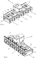
- Figures 1a and 1b show oblique views of a first embodiment of the storage and delivery station according to the invention.
- the storage and delivery station includes a base part 100 and a storage container 200, which are designed as separate components in the first embodiment.
- the base part 100 is part of an assembly of five base parts 100.
- the base parts can be designed separately from one another.
- the components mentioned in the following description of the base part 100 are each present in each base part 100, regardless of whether they are composite (as in Figs Figures 1a and 1b ) or executed separately.
- Each base part 100 comprises a lower section 130 and an upper section 120.
- the upper section 120 comprises a projection 121 onto which a reservoir 200 can be slid.
- a lower housing section of the reservoir 200 is adapted to the geometry of the projection 121 .
- a chute 140 is formed in the above-mentioned end face, via which separated medicament portions are transferred from a storage and delivery station to a guide device within the blister machine.
- the chute 140 extends through the base part 100 to the projection 121 in which an opening 123 for receiving a medicament portion is formed.
- a contact means 124 is provided on the aforementioned end face of the base part 100, with which the storage and dispensing station can be electrically coupled to the blister machine and via which electrical charges can be discharged from the blister machine.
- the contact means 124 is arranged in the face section of the upper section of the base part 100
- the contact means 124 can also be arranged in the face section of the lower section 130 .
- the contact means can be designed, for example, as a plug or the like. It is also possible, with an appropriate design of the reservoir, to To arrange contact means in this. It is essential that electrical charges can be delivered to the blister machines (not shown) via the contact means.
- a contact element 122 is arranged in the projection, which is electrically coupled to the contact means 124 on the one hand and to the electrically conductive outer surface of a separating device (not shown here) on the other hand.
- the contact element is part of the line device.
- the contact element is dependent on the precise configuration of the line device of the first embodiment.
- the line device can also be provided in such a way that the use of a contact element designed as a separate component is superfluous (see the embodiments described further below).
- the position is not limited to the illustrated one, the contact element can also be formed outside the projection.
- FIG 2 shows an oblique view of the storage container according to the first embodiment of the storage and delivery station according to the invention.
- the base part 100 and the storage container 200 are designed as separate components of the storage and delivery station.
- the reservoir 200 includes a housing 210 having a one (in figure 3 illustrated) circular-cylindrical receiving space 211 comprehensive portion 217 (receiving space portion), a lower portion 212 and a handle element 214.
- the reservoir 200 also includes a lid 213, which can be removed, among other things, to refill drug portions.
- figure 3 12 is a sectional view of the reservoir according to the first embodiment.
- the arrangement of a separating device 230 in the receiving space 211 of the receiving section 217 of the housing 210 can be seen from this sectional view.
- the separating device 230 is designed as a type of rotor with a plurality of projections 234 and channels 235 which extend through the separating device 230 in the axial direction.
- the channels 235 are defined by the protrusions 234 on a central component of the singulator 230 such that the channels are open to the outer periphery of the singulator.
- the separating device 230 comprises a central conical cover surface 232 which, together with the housing 210, defines a receiving space 202 for medicament portions. Due to the conical design of the top surface, portions of medication lying on it slide towards the channels 235.
- a step is formed between the conical top surface 232 and the projections 234, so that a type of annular space is formed in the area above the channels and the projections.
- a corresponding annular space can promote the supply of medicament portions into the channels.
- the bottom surface 220 has a dispensing opening 221, via which separated portions of medication can be dispensed through an opening 123 in the projection 121 of the base part 100 (see Figure 1a ) of the chute 140 are fed.
- a retaining section 216 of a retaining means 215 is introduced into the annular space above the discharge opening 221 .
- an opening is provided in the circular-cylindrical section 211 of the housing 210 .
- the function of the retaining means, and particularly the retaining portion, is to retain portions of medicament located in the receiving space 202 over the dispensing port when a channel 235 is aligned with the dispensing port 221 .
- a separation or dispensing of medicament portions takes place in that a channel containing a defined number of medicament portions is moved over the dispensing opening 221 so that the defined number of medicament portions can be dispensed from the aligned channel.
- the retaining portion 216 prevents that Overlying drug portions are also dispensed, so that it is ensured that only the number of drug portions arranged in a channel is dispensed.
- the separating device 230 also includes a coupling means 240, with which the separating device 230 can be coupled to a drive, via which the separating device can be rotated for the purpose of separating medicament portions.
- the coupling means is designed as a separate component, but alternatively it can also be provided that the coupling means is an integral part of the separating device 230 .
- the separating device is electrically conductive at least on its outer surface that comes into contact with the medicament portions to be separated.
- the separating device has a surface conductive coating 231 .
- the line device comprises a contact element 236, 237 arranged in the separating device 230.
- the separating device 230 is accommodated almost completely in the accommodation space 211 .
- the projections 245 end below the opening of the receiving space 211, so that a kind of annular space is created above it.
- the receiving space or the separating device
- the receiving space can also be designed in such a way that the projections exceed the upper opening of the receiving space.
- drug portions also enter the channels from the side.
- the precise configuration of the receiving space and the separating device depends on the medicament portions to be separated.
- FIG 4 two variants of the arrangement of the contact element are shown; once the contact element is arranged at the outer area of a projection 234 and once in the bottom surface of a projection 234 .
- An electrical coupling with a slip ring 222 , 215 arranged in the bottom surface 220 and/or the receiving section 217 is established with the contact element.
- the arrangement of the aforementioned slip rings in the bottom surface 220 and the receiving portion 217 is in the Figures 5 and 6 illustrated.
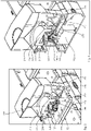
- figure 5 shows a further sectional view of a storage container placed on a base part according to the first embodiment.
- figure 6 shows a sectional view of the complete storage and delivery station according to the first embodiment
- Figures 5 and 6 illustrate in particular the coupling between the base part 100 and reservoir 200, which are designed as separate components.
- the reservoir 200 is pushed onto the projection 121 of the base part 100 at its lower section 212, for which purpose the lower section 212 is adapted accordingly.
- figure 6 also illustrates the coupling between the separating device 230 and a drive arranged in the base part.
- the drive comprises a motor 112, a drive shaft 111 and a drive hub 110.
- An outer contour of the drive hub 110 interacts in a non-positive manner with an inner contour of the coupling means 240, which in turn interacts with the separating device itself via a corresponding connection.
- the coupling means 240 can be an integral part of the separating device 230 .
- the separating device 230 is at the Figures 5 and 6 shown in a dispensing position.
- a canal is on the Aligned dispensing opening 221 in the bottom surface 220, drug portions arranged in the channel fall through the dispensing opening 221 into the chute 140 and from there get into the interior of the blister machine.
- the retaining section 216 of the retaining element 215 is introduced into the annular space above the channel aligned with the dispensing opening 221 and ensures that no further portions of medicament slip out of the receiving space.
- figure 7 shows an exploded view of the separating device 230/drive transition in a second embodiment of the storage and delivery station according to the invention.
- the outer contour of the drive hub 110 can be seen in an opening in the projection 121 of the upper section of the base part.
- the coupling means 240 can be seen above this and the separating device 230 above this.
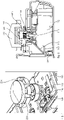
- figure 8 shows a sectional view through the second embodiment, with a large part of the storage container being left out, in order in particular to show the coupling between the separating device and the drive.
- An electric motor 112 is arranged centrally in the base part 100 and is connected to the contact means 124 via a line 113 .
- the contact means serves, among other things, as a power supply for the electric motor 112.
- further components inside the base part or the reservoir can be connected to a control device (not shown) via the contact means.
- a sensor (not shown) can be associated with the chute 140 or the dispensing opening in the base of the storage container, which sensor determines whether a medicament portion is actually dispensed during a separating process.
- the electric motor 112 includes a drive shaft 111 which ends in a drive hub 110 .
- the drive hub 110 has an outer contour (see figure 7 ), which with an inner contour 241 of the coupling means 240 interacts positively and detachably.
- the coupling means 240 is (detachably) connected to the separating device.
- connection between the drive hub 110 and the coupling means 240 of the separating device ensures that the storage container can be easily lifted off the base part without any further work steps.
- the coupling means is formed separately in relation to the separating device 230, but a connection between the coupling means 240 and the separating device remains when it is lifted off.
- a line device to be provided, via which the electrically conductive outer surface 231 of the separating device 230 is electrically conductively coupled to the contact means.
- the coupling means 240, the drive hub 110, the drive shaft 111 and the electric motor 110 represent components of the line device.
- the coupling means 240 is electrically conductive and conductively connected to the electrically conductive outer surface 231 of the isolating device 230 . This can be achieved, for example, by using a singulator that consists entirely of a conductive material (for example an electrically conductive plastic). Alternatively, lines can be provided from the outer surface to the coupling means.
- the drive hub and the drive shaft are also electrically conductive, with regard to the precise embodiment stated above applies.
- the electrostatic charge that occurs during the separation or isolation can be dissipated via the outer surface of the isolation device to the coupling means, and from there to the drive hub and drive shaft.
- the charge can be discharged from the drive shaft via the motor and the line 113 to the contact means 124, via which the charge is finally discharged or can be discharged to the blister machine.
- the separating device and/or other components of the reservoir are earthed, as it were, via the blister machine.
Landscapes
- Physics & Mathematics (AREA)
- General Physics & Mathematics (AREA)
- Medical Preparation Storing Or Oral Administration Devices (AREA)
- Packages (AREA)
- Basic Packing Technique (AREA)
Priority Applications (1)
| Application Number | Priority Date | Filing Date | Title |
|---|---|---|---|
| EP22160684.1A EP4044136A1 (de) | 2017-02-03 | 2017-02-03 | Vorrats- und abgabestation für einen blisterautomaten |
Applications Claiming Priority (2)
| Application Number | Priority Date | Filing Date | Title |
|---|---|---|---|
| EP22160684.1A EP4044136A1 (de) | 2017-02-03 | 2017-02-03 | Vorrats- und abgabestation für einen blisterautomaten |
| EP17154512.2A EP3358538B1 (de) | 2017-02-03 | 2017-02-03 | Vorrats- und abgabestation für einen blisterautomaten |
Related Parent Applications (1)
| Application Number | Title | Priority Date | Filing Date |
|---|---|---|---|
| EP17154512.2A Division EP3358538B1 (de) | 2017-02-03 | 2017-02-03 | Vorrats- und abgabestation für einen blisterautomaten |
Publications (1)
| Publication Number | Publication Date |
|---|---|
| EP4044136A1 true EP4044136A1 (de) | 2022-08-17 |
Family
ID=57965766
Family Applications (2)
| Application Number | Title | Priority Date | Filing Date |
|---|---|---|---|
| EP22160684.1A Pending EP4044136A1 (de) | 2017-02-03 | 2017-02-03 | Vorrats- und abgabestation für einen blisterautomaten |
| EP17154512.2A Active EP3358538B1 (de) | 2017-02-03 | 2017-02-03 | Vorrats- und abgabestation für einen blisterautomaten |
Family Applications After (1)
| Application Number | Title | Priority Date | Filing Date |
|---|---|---|---|
| EP17154512.2A Active EP3358538B1 (de) | 2017-02-03 | 2017-02-03 | Vorrats- und abgabestation für einen blisterautomaten |
Country Status (9)
| Country | Link |
|---|---|
| EP (2) | EP4044136A1 (pt) |
| JP (1) | JP2020507363A (pt) |
| KR (2) | KR102504910B1 (pt) |
| CN (1) | CN110300996B (pt) |
| AU (2) | AU2018215105B2 (pt) |
| BR (1) | BR112019014486B1 (pt) |
| CA (1) | CA3047082A1 (pt) |
| SG (1) | SG11201906234UA (pt) |
| WO (1) | WO2018141497A1 (pt) |
Families Citing this family (4)
| Publication number | Priority date | Publication date | Assignee | Title |
|---|---|---|---|---|
| EP3616675B1 (de) * | 2018-08-31 | 2021-04-14 | Becton Dickinson Rowa Germany GmbH | Vorratsbehälter für eine vorrats- und abgabestation für arzneimittel |
| CN111532590B (zh) * | 2020-05-15 | 2021-01-22 | 滁州学院 | 一种多功能药盒 |
| US12036185B2 (en) | 2021-07-19 | 2024-07-16 | Optum, Inc. | System and method to count pills |
| JP2024048740A (ja) * | 2022-09-28 | 2024-04-09 | 株式会社タカゾノ | 薬剤供給装置 |
Citations (4)
| Publication number | Priority date | Publication date | Assignee | Title |
|---|---|---|---|---|
| JP2005059903A (ja) * | 2003-08-13 | 2005-03-10 | Yuyama Manufacturing Co Ltd | 錠剤フィーダ |
| WO2013034504A1 (en) | 2011-09-09 | 2013-03-14 | Carefusion Switzerland 317 Sàrl | System and method for packaging dosed quantities of solid drug portions |
| US8833603B1 (en) * | 2013-03-29 | 2014-09-16 | Innovation Associates, Inc. | Apparatus for counting and dispensing pills with a vibrating plate |
| EP3040953A1 (en) * | 2014-12-31 | 2016-07-06 | JVM Co., Ltd. | Drug dispensing system and method for controlling the same |
Family Cites Families (9)
| Publication number | Priority date | Publication date | Assignee | Title |
|---|---|---|---|---|
| US4616316A (en) * | 1982-07-01 | 1986-10-07 | The United States Of America As Represented By The Administrator Of Veterans Affairs | Medication compliance monitoring device having conductive traces upon a frangible backing of a medication compartment |
| JP3519835B2 (ja) * | 1995-09-05 | 2004-04-19 | 三洋電機株式会社 | 固形製剤充填装置 |
| JPH0995312A (ja) * | 1995-09-29 | 1997-04-08 | Sanyo Electric Co Ltd | 固形製剤充填装置 |
| JP4107883B2 (ja) * | 2002-06-06 | 2008-06-25 | 三洋電機株式会社 | 薬剤ケース及びこの薬剤ケースを備えた薬剤包装装置 |
| GB201003275D0 (en) * | 2010-02-26 | 2010-04-14 | Portal Medical Ltd | Method of manufacturing a medicament dispenser device |
| DK2703299T3 (en) * | 2012-08-31 | 2016-06-06 | Carefusion Switzerland 317 Sarl | A storage and metering station for storing and dispensing metered amounts of solid drug servings |
| KR101449717B1 (ko) * | 2013-01-02 | 2014-10-15 | 주식회사 인포피아 | 약제 포장장치용 정제 카트리지 |
| JP5960676B2 (ja) * | 2013-12-25 | 2016-08-02 | キヤノンマーケティングジャパン株式会社 | 錠剤供給装置 |
| EP2962956B1 (de) * | 2014-07-03 | 2016-11-16 | Becton Dickinson Rowa Germany GmbH | Vorratsbehälter für eine Vorrichtung zum automatisierten Abgeben einzelner Medikamentenportionen |
-
2017
- 2017-02-03 EP EP22160684.1A patent/EP4044136A1/de active Pending
- 2017-02-03 EP EP17154512.2A patent/EP3358538B1/de active Active
-
2018
- 2018-01-03 CN CN201880010107.0A patent/CN110300996B/zh active Active
- 2018-01-03 JP JP2019539274A patent/JP2020507363A/ja active Pending
- 2018-01-03 AU AU2018215105A patent/AU2018215105B2/en active Active
- 2018-01-03 CA CA3047082A patent/CA3047082A1/en active Pending
- 2018-01-03 KR KR1020227036907A patent/KR102504910B1/ko active IP Right Grant
- 2018-01-03 KR KR1020197018419A patent/KR102459603B1/ko active IP Right Grant
- 2018-01-03 BR BR112019014486-2A patent/BR112019014486B1/pt active IP Right Grant
- 2018-01-03 WO PCT/EP2018/050133 patent/WO2018141497A1/de active Application Filing
- 2018-01-03 SG SG11201906234UA patent/SG11201906234UA/en unknown
-
2022
- 2022-07-26 AU AU2022209243A patent/AU2022209243A1/en not_active Abandoned
Patent Citations (4)
| Publication number | Priority date | Publication date | Assignee | Title |
|---|---|---|---|---|
| JP2005059903A (ja) * | 2003-08-13 | 2005-03-10 | Yuyama Manufacturing Co Ltd | 錠剤フィーダ |
| WO2013034504A1 (en) | 2011-09-09 | 2013-03-14 | Carefusion Switzerland 317 Sàrl | System and method for packaging dosed quantities of solid drug portions |
| US8833603B1 (en) * | 2013-03-29 | 2014-09-16 | Innovation Associates, Inc. | Apparatus for counting and dispensing pills with a vibrating plate |
| EP3040953A1 (en) * | 2014-12-31 | 2016-07-06 | JVM Co., Ltd. | Drug dispensing system and method for controlling the same |
Also Published As
| Publication number | Publication date |
|---|---|
| CN110300996A (zh) | 2019-10-01 |
| KR102459603B1 (ko) | 2022-10-27 |
| AU2022209243A1 (en) | 2022-08-18 |
| CA3047082A1 (en) | 2018-08-09 |
| CN110300996B (zh) | 2022-05-31 |
| BR112019014486B1 (pt) | 2024-01-30 |
| WO2018141497A1 (de) | 2018-08-09 |
| SG11201906234UA (en) | 2019-08-27 |
| KR20190113767A (ko) | 2019-10-08 |
| KR20220150991A (ko) | 2022-11-11 |
| AU2018215105A1 (en) | 2019-07-11 |
| JP2020507363A (ja) | 2020-03-12 |
| EP3358538B1 (de) | 2022-03-30 |
| KR102504910B1 (ko) | 2023-03-02 |
| EP3358538A1 (de) | 2018-08-08 |
| AU2018215105B2 (en) | 2022-05-19 |
| BR112019014486A2 (pt) | 2020-02-11 |
Similar Documents
| Publication | Publication Date | Title |
|---|---|---|
| EP3358538B1 (de) | Vorrats- und abgabestation für einen blisterautomaten | |
| DE69011749T2 (de) | Fördervorrichtung für Gegenstände. | |
| EP2962956B1 (de) | Vorratsbehälter für eine Vorrichtung zum automatisierten Abgeben einzelner Medikamentenportionen | |
| EP3925590A1 (de) | Vorratsbehälter für eine vorrats- und abgabestation | |
| DE102011083029B4 (de) | Rotationsfördervorrichtung und Verfahren zum Fördern von Artikeln der tabakverarbeitenden Industrie | |
| EP2989877B1 (de) | Dosieraggregat für körniges gut | |
| DE112008001243T5 (de) | Elektrostatisches Aufbringen eines Etiketts auf eine Formkavität | |
| EP2987395A1 (de) | Dosierscheibe eines verteilaggregats für körniges gut | |
| WO2021254738A1 (de) | Vorratsbehälter für eine vorrats- und abgabestation | |
| EP2180993B1 (de) | Sternverteiler | |
| DE10001570A1 (de) | Elektrostatischer Rotationszerstäuber | |
| EP3407854A1 (de) | Vorratsbehälter für eine vorrats- und abgabestation für arzneimittel | |
| EP3991712B1 (de) | Vorratsbehälter für eine vorrats- und abgabestation und vorrats- und abgabestation | |
| EP2251190A2 (de) | Rundläuferpresse | |
| WO2020043334A1 (de) | Vorratsbehälter für eine vorrats- und abgabestation für arzneimittel | |
| EP2925149B1 (de) | Teigformmaschine und verfahren zur herstellung eines gebäckstücks | |
| EP0224744A1 (de) | Vorrichtung zum Aufgurten von stäbchenförmigen Bauelementen, insbesondere elektrischen Bauelementen (MELFs) | |
| EP2734144B1 (de) | Auftragevorrichtung für dentalmassen | |
| EP3926594A1 (de) | Vorratsbehälter für eine vorrats- und abgabestation | |
| EP3879503A1 (de) | Vorrats- und abgabestation für arzneimittel | |
| EP3156338B1 (de) | Vorratsbehälter für eine vorrats- und abgabestation für arzneimittel | |
| EP1452235B1 (de) | Glockenteller und Rotationszerstäuber | |
| WO2022207301A1 (de) | Vorrats- und abgabestation für einen blisterautomaten | |
| DE1657252A1 (de) | Verfahren zum Bremsen und/oder Halten von Zigaretten | |
| WO2020039010A1 (de) | Fördertrommeleinheit für eine maschine zur herstellung von stabförmigen produkten der tabak verarbeitenden industrie |
Legal Events
| Date | Code | Title | Description |
|---|---|---|---|
| PUAI | Public reference made under article 153(3) epc to a published international application that has entered the european phase |
Free format text: ORIGINAL CODE: 0009012 |
|
| STAA | Information on the status of an ep patent application or granted ep patent |
Free format text: STATUS: THE APPLICATION HAS BEEN PUBLISHED |
|
| AC | Divisional application: reference to earlier application |
Ref document number: 3358538 Country of ref document: EP Kind code of ref document: P |
|
| AK | Designated contracting states |
Kind code of ref document: A1 Designated state(s): AL AT BE BG CH CY CZ DE DK EE ES FI FR GB GR HR HU IE IS IT LI LT LU LV MC MK MT NL NO PL PT RO RS SE SI SK SM TR |
|
| STAA | Information on the status of an ep patent application or granted ep patent |
Free format text: STATUS: REQUEST FOR EXAMINATION WAS MADE |
|
| 17P | Request for examination filed |
Effective date: 20230217 |
|
| RBV | Designated contracting states (corrected) |
Designated state(s): AL AT BE BG CH CY CZ DE DK EE ES FI FR GB GR HR HU IE IS IT LI LT LU LV MC MK MT NL NO PL PT RO RS SE SI SK SM TR |