EP4043709B1 - Elektrischer generator auf der basis von flüssigerdgas - Google Patents
Elektrischer generator auf der basis von flüssigerdgas Download PDFInfo
- Publication number
- EP4043709B1 EP4043709B1 EP20872769.3A EP20872769A EP4043709B1 EP 4043709 B1 EP4043709 B1 EP 4043709B1 EP 20872769 A EP20872769 A EP 20872769A EP 4043709 B1 EP4043709 B1 EP 4043709B1
- Authority
- EP
- European Patent Office
- Prior art keywords
- gas
- electric generator
- lpg
- generator
- compartment
- Prior art date
- Legal status (The legal status is an assumption and is not a legal conclusion. Google has not performed a legal analysis and makes no representation as to the accuracy of the status listed.)
- Active
Links
Images



Classifications
-
- F—MECHANICAL ENGINEERING; LIGHTING; HEATING; WEAPONS; BLASTING
- F02—COMBUSTION ENGINES; HOT-GAS OR COMBUSTION-PRODUCT ENGINE PLANTS
- F02D—CONTROLLING COMBUSTION ENGINES
- F02D19/00—Controlling engines characterised by their use of non-liquid fuels, pluralities of fuels, or non-fuel substances added to the combustible mixtures
- F02D19/06—Controlling engines characterised by their use of non-liquid fuels, pluralities of fuels, or non-fuel substances added to the combustible mixtures peculiar to engines working with pluralities of fuels, e.g. alternatively with light and heavy fuel oil, other than engines indifferent to the fuel consumed
- F02D19/0602—Control of components of the fuel supply system
- F02D19/0613—Switch-over from one fuel to another
- F02D19/0615—Switch-over from one fuel to another being initiated by automatic means, e.g. based on engine or vehicle operating conditions
-
- F—MECHANICAL ENGINEERING; LIGHTING; HEATING; WEAPONS; BLASTING
- F02—COMBUSTION ENGINES; HOT-GAS OR COMBUSTION-PRODUCT ENGINE PLANTS
- F02B—INTERNAL-COMBUSTION PISTON ENGINES; COMBUSTION ENGINES IN GENERAL
- F02B63/00—Adaptations of engines for driving pumps, hand-held tools or electric generators; Portable combinations of engines with engine-driven devices
- F02B63/04—Adaptations of engines for driving pumps, hand-held tools or electric generators; Portable combinations of engines with engine-driven devices for electric generators
- F02B63/044—Adaptations of engines for driving pumps, hand-held tools or electric generators; Portable combinations of engines with engine-driven devices for electric generators the engine-generator unit being placed on a frame or in an housing
-
- F—MECHANICAL ENGINEERING; LIGHTING; HEATING; WEAPONS; BLASTING
- F02—COMBUSTION ENGINES; HOT-GAS OR COMBUSTION-PRODUCT ENGINE PLANTS
- F02D—CONTROLLING COMBUSTION ENGINES
- F02D19/00—Controlling engines characterised by their use of non-liquid fuels, pluralities of fuels, or non-fuel substances added to the combustible mixtures
- F02D19/02—Controlling engines characterised by their use of non-liquid fuels, pluralities of fuels, or non-fuel substances added to the combustible mixtures peculiar to engines working with gaseous fuels
- F02D19/021—Control of components of the fuel supply system
- F02D19/023—Control of components of the fuel supply system to adjust the fuel mass or volume flow
-
- F—MECHANICAL ENGINEERING; LIGHTING; HEATING; WEAPONS; BLASTING
- F02—COMBUSTION ENGINES; HOT-GAS OR COMBUSTION-PRODUCT ENGINE PLANTS
- F02D—CONTROLLING COMBUSTION ENGINES
- F02D19/00—Controlling engines characterised by their use of non-liquid fuels, pluralities of fuels, or non-fuel substances added to the combustible mixtures
- F02D19/02—Controlling engines characterised by their use of non-liquid fuels, pluralities of fuels, or non-fuel substances added to the combustible mixtures peculiar to engines working with gaseous fuels
- F02D19/025—Failure diagnosis or prevention; Safety measures; Testing
-
- F—MECHANICAL ENGINEERING; LIGHTING; HEATING; WEAPONS; BLASTING
- F02—COMBUSTION ENGINES; HOT-GAS OR COMBUSTION-PRODUCT ENGINE PLANTS
- F02D—CONTROLLING COMBUSTION ENGINES
- F02D29/00—Controlling engines, such controlling being peculiar to the devices driven thereby, the devices being other than parts or accessories essential to engine operation, e.g. controlling of engines by signals external thereto
- F02D29/06—Controlling engines, such controlling being peculiar to the devices driven thereby, the devices being other than parts or accessories essential to engine operation, e.g. controlling of engines by signals external thereto peculiar to engines driving electric generators
-
- F—MECHANICAL ENGINEERING; LIGHTING; HEATING; WEAPONS; BLASTING
- F02—COMBUSTION ENGINES; HOT-GAS OR COMBUSTION-PRODUCT ENGINE PLANTS
- F02M—SUPPLYING COMBUSTION ENGINES IN GENERAL WITH COMBUSTIBLE MIXTURES OR CONSTITUENTS THEREOF
- F02M21/00—Apparatus for supplying engines with non-liquid fuels, e.g. gaseous fuels stored in liquid form
- F02M21/02—Apparatus for supplying engines with non-liquid fuels, e.g. gaseous fuels stored in liquid form for gaseous fuels
- F02M21/0203—Apparatus for supplying engines with non-liquid fuels, e.g. gaseous fuels stored in liquid form for gaseous fuels characterised by the type of gaseous fuel
- F02M21/0209—Hydrocarbon fuels, e.g. methane or acetylene
- F02M21/0212—Hydrocarbon fuels, e.g. methane or acetylene comprising at least 3 C-Atoms, e.g. liquefied petroleum gas [LPG], propane or butane
-
- F—MECHANICAL ENGINEERING; LIGHTING; HEATING; WEAPONS; BLASTING
- F02—COMBUSTION ENGINES; HOT-GAS OR COMBUSTION-PRODUCT ENGINE PLANTS
- F02M—SUPPLYING COMBUSTION ENGINES IN GENERAL WITH COMBUSTIBLE MIXTURES OR CONSTITUENTS THEREOF
- F02M21/00—Apparatus for supplying engines with non-liquid fuels, e.g. gaseous fuels stored in liquid form
- F02M21/02—Apparatus for supplying engines with non-liquid fuels, e.g. gaseous fuels stored in liquid form for gaseous fuels
- F02M21/0218—Details on the gaseous fuel supply system, e.g. tanks, valves, pipes, pumps, rails, injectors or mixers
- F02M21/0293—Safety devices; Fail-safe measures
Definitions
- the present invention relates to the development of an electric generator that integrates in a single frame one or more liquefied petroleum gas (LPG) fuel tanks and a generator set, thus obtaining an electric generator powered by LPG with a great compactness that allows the frequent relocation of said generator since a reduction in the logistics necessary for its transfer and installation is achieved.
- LPG liquefied petroleum gas
- the present invention satisfies this demand.
- the electric generator according to the present invention arises from the high inefficiency associated with the relocation of the generator sets powered by LPG, used in the rental applications sector. Due to the characteristics of the sector, in which generator sets are rented to provide energy for different events and applications, in different locations that require the transfer of the elements that allow electricity generation, which mainly include the generator set and the fuel tank(s).
- the present invention relates to an electric generator comprising a frame defining a first compartment and a second compartment.
- the generator comprises a generator set established in the first compartment.
- the electric generator comprises at least one tank of liquefied petroleum gas, LPG, established in the second compartment and a liquid-phase feed gas train that connects said tank to the generator set for the supply of LPG.
- the present invention consists of new electrical generation equipment supplied entirely with liquefied petroleum gases LPG in which the LPG tank itself is integrated with the generator set in the same single structure or frame.
- the exclusive use of a gaseous fuel source requires that the tank be pressurized and, therefore, the generator can include auxiliary systems to condition said fuel.
- the present invention focuses on applications of generator sets that use LPG as fuel for electricity generation for the rental sector, which is strongly driven by aspects such as noise pollution, engine efficiency, gas emissions and eventual increase in energy demand.
- the present invention relates to an electric generator that allows reducing the logistics necessary for uses and applications involving frequent relocation.
- the electric generator according to the present invention intends to respond to the needs of the rental sector by developing compact generator equipment that integrates the LPG fuel tanks in the same equipment, maintaining the conditions of safety, autonomy and compactness and increasing ease of transfer while reducing the logistics required for relocation.
- the generator sets according to the present invention comprise four different powers, one of 25, 40, 70 and 110 kVA, which allow their application to be validated within the ranges of the range intended for the rental sector.
- the generator comprises three LPG tanks with a useful capacity of 450 liters.
- the LPG tanks are sized to ensure autonomy of at least 26 hours in the preferred embodiment of 70 kVA, operating at a normal regime of 75% of the nominal load of the generator set of the electric generator.
- the electric generator includes a single filling point for the three tanks.
- the electric generator includes a system for external feeding both in liquid phase and in vapor phase.
- the electric generator may comprise a second gas train that connects a gas source external to the electric generator to the generator set for the supply of LPG.
- the electric generator accepts motorization and generators for both 50 Hz and 60 Hz.
- the electric generator comprises a frame that defines two compartments which can be divided by a rock wool partition or the like in a first embodiment and by a sub-frame in a second embodiment.
- the electric generator comprises at least two gas sensors, one in each compartment of the frame to increase safety.
- the generator can be programmed to stop its operation immediately after detecting a presence of gas above the established limit.
- the electric generator includes safety valves and conduits that evacuate the gas to the outside of the generator set in the event that excess pressure is detected inside the fuel tanks.
- the electric generator (100) shown in Figure 1 powered by LPG comprises a single frame (110) which is shown in its entirety in Figure 2A .
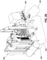
- the electric generator (100) also comprises a generator set (120) and a set of pressurized LPG tanks or reservoirs (130), in particular, three LPG tanks, which are shown in Figure 2B .
- the electric generator (100) of Figure 1 has a power of 25 kVA. In other preferred embodiments, the electric generator (100) can have powers of 40, 70 and 110 kVA.
- the three LPG tanks or reservoirs (130) have a useful capacity of 450 liters, which may require 15 minutes to be fully refueled.
- the frame (110) it comprises inside a first part or compartment (110a) and a second part or compartment (110b) as can be seen in Figure 2A .
- the frame (110) of the electric generator (100) includes a separation partition or barrier (150) and a casing (112) as well as ventilation means (114).
- the first compartment (110a) is adapted to house the generator set (120).
- the second compartment (110b) is adapted to house the LPG tanks or reservoirs (130).
- the frame (110) of Figure 2A is a single indivisible frame that forms two compartments (110a, 11b): one for the generator set (120), that is, for motorization and electricity generation, and another for LPG tanks or reservoirs (130).
- the frame (110) includes bulkhead fittings for fuel lines, sensors and electronics.
- the bulkhead fittings and flexible pipes prevent vibrations caused by the operation of the generator set.
- the electric generator (100) can comprise two gas detectors per compartment (110a, 110b) to speed up the detection of potential leaks.
- the frame (110) includes openings at the bottom of the frame (110) to vent potentially explosive accumulations inside the bodywork.
- the electric generator (100) comprises a liquid-phase feed gas train (140) which is shown in Figure 4 and which connects the three LPG tanks or reservoirs (130) of the electric generator (100) to the generator set (120) for the supply of LPG to the generator set (120).
- the liquid-phase feed gas train (140) for feeding the generator set (120) with LPG gas stored in the LPG tanks may include a manual valve, a particulate filter, a primary pressure regulator, a solenoid valve, a vaporizer, a low pressure switch and pressure gauges for the inlet and outlet of the gas train (140).
- the three LPG tanks or reservoirs (130) established in the second compartment (110b) are independently isolated from the generator set (112) and from the necessary pipes and elements by means of a separation partition or barrier (150) that may comprise rock wool.
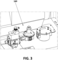
- FIG. 2B and 3 Also seen is a second gas-phase feed gas train 160 shown in Figures 2B and 3 which is established in frame compartment 110a.
- the second gas-phase feed gas train (160) connects an external gas source to the generator set (120) for the supply of LPG or NG (Natural Gas) to the generator set (120).
- LPG or NG Natural Gas
- the gas-phase feed gas train (160) for the external supply of the generator set (120) with LPG or NG gas may include a manual valve, a particulate filter, a primary pressure regulator, a double solenoid valve, a low and high pressure switch and pressure gauges for the inlet and outlet of the gas train (140).
- control panel To manage these three possibilities of fuel supply to the generator, there is an optional selector on the control panel with three positions depending on the option chosen: supply from internal LPG tanks in liquid phase, external supply of LPG in gaseous phase or external supply in gaseous phase of NG.
- FIG 2B shows the installation of the LPG tanks or reservoirs (130) in the lower part of the generator set (120), in the part farthest from the main heat sources.
- Two critical points in heat generation are identified: Peaks of maximum power requirements continued over time, and after stopping the generator set engine, at which time the cooling system stops working and heat continues to be emitted from the hot spots of the system.
- the separation partition or barrier (150) of the frame (110) shown in Figure 2A comprises rock wool between the first compartment (110a) and second compartment (110b) of the frame (110).
- the LPG tanks or reservoirs (130) have been isolated in the second compartment (110b) of the frame (110) and are independent of the generator set (120) established in the first compartment (110a) of the frame (110).
- the first and second compartments (110a, 110b) comprise direct outlets to the outside for possible gas leaks.
- the first and second compartments (110a, 110b) comprise gas sensors.
- the compartment (110b) comprises passive ventilation for the LPG tanks or reservoirs (130) directly with the outside and ducts for the overpressure valves that expel the gas directly to the outside of the frame (110b).
- the frame (110) comprises a subframe between the two compartments (110a, 110b) where the generator set (120) and the LPG tanks or reservoirs (130) are located, replacing the partition with rock wool.
- This subframe allows greater insulation than the separation partition or barrier (150) with rock wool in the event of an increase in the power of the electric generator (100) from 25 kVA to 110 kVA in a second preferred embodiment.
- the frame (110) comprises means of access (116) to the generator set (120) and to the LPG tanks or reservoirs (130) shown in Figures 1 and 2A for disassembling parts of the generator set (116) for maintenance, and for access to the fuel tanks without the need to disassemble the entire generator set.
Landscapes
- Engineering & Computer Science (AREA)
- Chemical & Material Sciences (AREA)
- Combustion & Propulsion (AREA)
- Mechanical Engineering (AREA)
- General Engineering & Computer Science (AREA)
- Oil, Petroleum & Natural Gas (AREA)
- Chemical Kinetics & Catalysis (AREA)
- General Chemical & Material Sciences (AREA)
- Health & Medical Sciences (AREA)
- Biomedical Technology (AREA)
- Filling Or Discharging Of Gas Storage Vessels (AREA)
Claims (10)
- Stromgenerator (100), der mit verflüssigtem Erdgas, LPG, läuft, umfassend:ein Gerüst (110), das ein erstes Kompartiment (110a) und ein zweites Kompartiment (110b) umfasst, undeinen Generatorsatz (120), der durch LPG angetrieben wird und sich im ersten Kompartiment (110a) befindet, undwobei der Stromgenerator (100) wenigstens einen LPG-Tank (130) umfasst, der sich im zweiten Kompartiment (110b) befindet;und eine erste Regelstrecke (140) für das Zufuhrgas in der flüssigen Phase, die den wenigstens einen LPG-Tank (130) mit dem Generatorsatz (120) verbindet, um dem Generatorsatz (120) LPG zuzuführen, undgekennzeichnet durch einen ersten Gaslecksensor im ersten Kompartiment (110a) des Gerüsts (110) und einen zweiten Gaslecksensor im zweiten Kompartiment (110b) des Gerüsts (110).
- Stromgenerator (100) gemäß Anspruch 1, weiterhin umfassend eine zweite Regelstrecke (160) für das Zufuhrgas in der Gasphase, die eine bezüglich des Stromgenerators externe Gasquelle mit dem Generatorsatz (120) verbindet, um dem Generatorsatz (120) LPG zuzuführen.
- Stromgenerator (100) gemäß einem der vorstehenden Ansprüche, wobei das Gerüst (110) Ventilationseinrichtungen (114) umfasst.
- Stromgenerator (100) gemäß einem der vorstehenden Ansprüche, wobei das Gerüst (110) Verankerungseinrichtungen für die Montage des Stromgenerators (100) auf einem Transporteranhänger umfasst.
- Stromgenerator (100) gemäß einem der vorstehenden Ansprüche, umfassend drei LPG-Kraftstofftanks (130).
- Stromgenerator (100) gemäß einem der vorstehenden Ansprüche, wobei das Gerüst (110) eine Sperre (150) mit Steinwolle umfasst und
wobei das erste Kompartiment (110a) und das zweite Kompartiment (110b) durch die Sperre (150) mit Steinwolle voneinander getrennt sind. - Stromgenerator (100) gemäß Anspruch 1 bis 5, wobei das Gerüst (110) ein Teilgerüst umfasst und
wobei das erste Kompartiment (110a) und das zweite Kompartiment (110b) durch das Teilgerüst voneinander getrennt sind. - Stromgenerator (100) gemäß einem der vorstehenden Ansprüche, wobei das Gerüst (110) Einrichtungen zum Zugang (116) zum Generatorsatz (120) und zu den LPG-Tanks oder -Reservoirs (130) umfasst.
- Stromgenerator (100) gemäß einem der vorstehenden Ansprüche, wobei das Gerüst (110) ein Gehäuse (112) umfasst.
- Stromgenerator (100) gemäß Anspruch 2 bis 9, wobei der Stromgenerator (100) eine elektrische Schalttafel mit einem Kraftstoffselektor umfasst, welcher drei Positionen umfasst:eine erste Position zum internen Zuführen einer flüssigen Phase aus dem wenigstens einen LPG-Tank (130) durch die erste Gasregelstrecke (140);eine zweite Position zum externen Zuführen einer Gasphase aus der externen Gasquelle, in der LPG gespeichert ist, durch die zweite Gasregelstrecke (160); undeine dritte Position zum externen Zuführen einer Gasphase aus der externen Gasquelle, in der Erdgas (NG) gespeichert ist, durch die zweite Gasregelstrecke (160).
Applications Claiming Priority (2)
| Application Number | Priority Date | Filing Date | Title |
|---|---|---|---|
| ES201930852A ES2817298A1 (es) | 2019-10-02 | 2019-10-02 | Generador eléctrico basado en gas licuado del petróleo |
| PCT/ES2020/070586 WO2021064267A2 (es) | 2019-10-02 | 2020-09-29 | Generador eléctrico basado en gas licuado del petróleo |
Publications (4)
| Publication Number | Publication Date |
|---|---|
| EP4043709A2 EP4043709A2 (de) | 2022-08-17 |
| EP4043709A4 EP4043709A4 (de) | 2023-05-24 |
| EP4043709B1 true EP4043709B1 (de) | 2025-02-26 |
| EP4043709C0 EP4043709C0 (de) | 2025-02-26 |
Family
ID=75265368
Family Applications (1)
| Application Number | Title | Priority Date | Filing Date |
|---|---|---|---|
| EP20872769.3A Active EP4043709B1 (de) | 2019-10-02 | 2020-09-29 | Elektrischer generator auf der basis von flüssigerdgas |
Country Status (3)
| Country | Link |
|---|---|
| EP (1) | EP4043709B1 (de) |
| ES (1) | ES2817298A1 (de) |
| WO (1) | WO2021064267A2 (de) |
Family Cites Families (10)
| Publication number | Priority date | Publication date | Assignee | Title |
|---|---|---|---|---|
| JPH0223258A (ja) * | 1988-07-11 | 1990-01-25 | Yamaha Motor Co Ltd | ガスエンジン |
| JPH05133240A (ja) * | 1991-11-12 | 1993-05-28 | Mitsubishi Heavy Ind Ltd | ガスエンジン発電機 |
| JP4486519B2 (ja) * | 2005-01-31 | 2010-06-23 | 三菱重工業株式会社 | ガスエンジン作業機 |
| US9765918B2 (en) * | 2007-02-06 | 2017-09-19 | Bernardo J. Herzer | Portable gas powered internal combustion engine arrangement |
| CN101131119A (zh) * | 2007-09-03 | 2008-02-27 | 云南蓝海新能源投资有限公司 | 模块化5000kw多燃料发电机组 |
| CN104047710B (zh) * | 2014-05-30 | 2016-07-06 | 浙江耀锋动力科技有限公司 | 多燃料发电机组 |
| US10697398B2 (en) * | 2015-06-12 | 2020-06-30 | Champion Power Equipment, Inc. | Batteryless dual fuel engine with liquid fuel cut-off |
| CN205243648U (zh) * | 2015-11-23 | 2016-05-18 | 华鼎电源(天津)有限公司 | 一种气罐内置式lpg箱式静音发电机组 |
| DK3249201T3 (da) * | 2016-05-24 | 2020-08-03 | CleanTech Swiss AG | Indretning til drift af en motor |
| CN208330559U (zh) * | 2016-09-21 | 2019-01-04 | 布里格斯斯特拉顿公司 | 具有多个燃料阀的便携式发电机 |
-
2019
- 2019-10-02 ES ES201930852A patent/ES2817298A1/es active Pending
-
2020
- 2020-09-29 EP EP20872769.3A patent/EP4043709B1/de active Active
- 2020-09-29 WO PCT/ES2020/070586 patent/WO2021064267A2/es not_active Ceased
Also Published As
| Publication number | Publication date |
|---|---|
| WO2021064267A3 (es) | 2021-07-22 |
| ES2817298A1 (es) | 2021-04-06 |
| EP4043709C0 (de) | 2025-02-26 |
| WO2021064267A2 (es) | 2021-04-08 |
| EP4043709A4 (de) | 2023-05-24 |
| EP4043709A2 (de) | 2022-08-17 |
Similar Documents
| Publication | Publication Date | Title |
|---|---|---|
| US8207621B2 (en) | Modular panels for enclosures | |
| US10006409B2 (en) | Locomotive on-board storage and delivery of gaseous fuel | |
| Miller et al. | System design of a large fuel cell hybrid locomotive | |
| CN102224066B (zh) | 搭载在液化气运输船的再液化装置 | |
| JP3906747B2 (ja) | 低沸点燃料を使用する燃料供給装置およびその制御方法 | |
| US9925847B2 (en) | Heating and cooling systems and methods for truck cabs | |
| US11407283B2 (en) | Cab heating systems and methods for vehicles | |
| CN103748632B (zh) | 用于核设施的紧急供应的装置和方法 | |
| CN104010915A (zh) | 向内燃机供应气体燃料的方法和装置 | |
| US20140123916A1 (en) | Utilizing Locomotive Electrical Locker to Warm Liquid Natural Gas | |
| EP4043709B1 (de) | Elektrischer generator auf der basis von flüssigerdgas | |
| KR20150026674A (ko) | 부유 저장식 가스 발전플랜트의 배치구조 | |
| JP2012154486A (ja) | 移動式圧縮ガス分配装置 | |
| CN108091906B (zh) | 燃料电池装置,具有其的车辆和燃料电池装置的操作方法 | |
| US20140138045A1 (en) | Compressed natural gas refrigerated vehicle and regulator therefor | |
| ES1305457U (es) | Generador eléctrico basado en gas licuado del petróleo | |
| Rachow et al. | Concept for a LNG Gas Handling System for a Dual Fuel Engine | |
| JP4150948B2 (ja) | 液化ガス供給装置 | |
| CN114872936A (zh) | 卫星轨控动力系统 | |
| Surampudi et al. | Electrification and integration of accessories on a class-8 tractor | |
| RU226364U1 (ru) | Автономный СПГ энергетический комплекс | |
| KR20220021299A (ko) | 선박 | |
| KR102851688B1 (ko) | 이동 및 운송이 편리한 컨테이너 타입 이동식 lng 충전시스템 | |
| NO20230822A1 (en) | System and method for generating and providing hydrogen gas to a combustion engine | |
| WO2025177264A1 (en) | Optiprime hybrid generator |
Legal Events
| Date | Code | Title | Description |
|---|---|---|---|
| STAA | Information on the status of an ep patent application or granted ep patent |
Free format text: STATUS: THE INTERNATIONAL PUBLICATION HAS BEEN MADE |
|
| PUAI | Public reference made under article 153(3) epc to a published international application that has entered the european phase |
Free format text: ORIGINAL CODE: 0009012 |
|
| STAA | Information on the status of an ep patent application or granted ep patent |
Free format text: STATUS: REQUEST FOR EXAMINATION WAS MADE |
|
| 17P | Request for examination filed |
Effective date: 20220427 |
|
| AK | Designated contracting states |
Kind code of ref document: A2 Designated state(s): AL AT BE BG CH CY CZ DE DK EE ES FI FR GB GR HR HU IE IS IT LI LT LU LV MC MK MT NL NO PL PT RO RS SE SI SK SM TR |
|
| DAV | Request for validation of the european patent (deleted) | ||
| DAX | Request for extension of the european patent (deleted) | ||
| A4 | Supplementary search report drawn up and despatched |
Effective date: 20230425 |
|
| RIC1 | Information provided on ipc code assigned before grant |
Ipc: F02M 21/02 20060101ALI20230419BHEP Ipc: F02D 29/06 20060101ALI20230419BHEP Ipc: F02D 19/02 20060101ALI20230419BHEP Ipc: F02B 63/04 20060101AFI20230419BHEP |
|
| GRAP | Despatch of communication of intention to grant a patent |
Free format text: ORIGINAL CODE: EPIDOSNIGR1 |
|
| STAA | Information on the status of an ep patent application or granted ep patent |
Free format text: STATUS: GRANT OF PATENT IS INTENDED |
|
| INTG | Intention to grant announced |
Effective date: 20240919 |
|
| GRAS | Grant fee paid |
Free format text: ORIGINAL CODE: EPIDOSNIGR3 |
|
| GRAA | (expected) grant |
Free format text: ORIGINAL CODE: 0009210 |
|
| STAA | Information on the status of an ep patent application or granted ep patent |
Free format text: STATUS: THE PATENT HAS BEEN GRANTED |
|
| AK | Designated contracting states |
Kind code of ref document: B1 Designated state(s): AL AT BE BG CH CY CZ DE DK EE ES FI FR GB GR HR HU IE IS IT LI LT LU LV MC MK MT NL NO PL PT RO RS SE SI SK SM TR |
|
| REG | Reference to a national code |
Ref country code: GB Ref legal event code: FG4D |
|
| REG | Reference to a national code |
Ref country code: CH Ref legal event code: EP |
|
| REG | Reference to a national code |
Ref country code: DE Ref legal event code: R096 Ref document number: 602020046962 Country of ref document: DE |
|
| REG | Reference to a national code |
Ref country code: IE Ref legal event code: FG4D |
|
| U01 | Request for unitary effect filed |
Effective date: 20250307 |
|
| U07 | Unitary effect registered |
Designated state(s): AT BE BG DE DK EE FI FR IT LT LU LV MT NL PT RO SE SI Effective date: 20250314 |
|
| PG25 | Lapsed in a contracting state [announced via postgrant information from national office to epo] |
Ref country code: RS Free format text: LAPSE BECAUSE OF FAILURE TO SUBMIT A TRANSLATION OF THE DESCRIPTION OR TO PAY THE FEE WITHIN THE PRESCRIBED TIME-LIMIT Effective date: 20250526 |
|
| PG25 | Lapsed in a contracting state [announced via postgrant information from national office to epo] |
Ref country code: PL Free format text: LAPSE BECAUSE OF FAILURE TO SUBMIT A TRANSLATION OF THE DESCRIPTION OR TO PAY THE FEE WITHIN THE PRESCRIBED TIME-LIMIT Effective date: 20250226 |
|
| PG25 | Lapsed in a contracting state [announced via postgrant information from national office to epo] |
Ref country code: ES Free format text: LAPSE BECAUSE OF FAILURE TO SUBMIT A TRANSLATION OF THE DESCRIPTION OR TO PAY THE FEE WITHIN THE PRESCRIBED TIME-LIMIT Effective date: 20250226 |
|
| PG25 | Lapsed in a contracting state [announced via postgrant information from national office to epo] |
Ref country code: IS Free format text: LAPSE BECAUSE OF FAILURE TO SUBMIT A TRANSLATION OF THE DESCRIPTION OR TO PAY THE FEE WITHIN THE PRESCRIBED TIME-LIMIT Effective date: 20250626 Ref country code: NO Free format text: LAPSE BECAUSE OF FAILURE TO SUBMIT A TRANSLATION OF THE DESCRIPTION OR TO PAY THE FEE WITHIN THE PRESCRIBED TIME-LIMIT Effective date: 20250526 |
|
| PG25 | Lapsed in a contracting state [announced via postgrant information from national office to epo] |
Ref country code: HR Free format text: LAPSE BECAUSE OF FAILURE TO SUBMIT A TRANSLATION OF THE DESCRIPTION OR TO PAY THE FEE WITHIN THE PRESCRIBED TIME-LIMIT Effective date: 20250226 |
|
| PG25 | Lapsed in a contracting state [announced via postgrant information from national office to epo] |
Ref country code: GR Free format text: LAPSE BECAUSE OF FAILURE TO SUBMIT A TRANSLATION OF THE DESCRIPTION OR TO PAY THE FEE WITHIN THE PRESCRIBED TIME-LIMIT Effective date: 20250527 |
|
| PG25 | Lapsed in a contracting state [announced via postgrant information from national office to epo] |
Ref country code: SM Free format text: LAPSE BECAUSE OF FAILURE TO SUBMIT A TRANSLATION OF THE DESCRIPTION OR TO PAY THE FEE WITHIN THE PRESCRIBED TIME-LIMIT Effective date: 20250226 |
|
| PGFP | Annual fee paid to national office [announced via postgrant information from national office to epo] |
Ref country code: GB Payment date: 20250904 Year of fee payment: 6 |
|
| PG25 | Lapsed in a contracting state [announced via postgrant information from national office to epo] |
Ref country code: CZ Free format text: LAPSE BECAUSE OF FAILURE TO SUBMIT A TRANSLATION OF THE DESCRIPTION OR TO PAY THE FEE WITHIN THE PRESCRIBED TIME-LIMIT Effective date: 20250226 |
|
| U20 | Renewal fee for the european patent with unitary effect paid |
Year of fee payment: 6 Effective date: 20250912 |
|
| PG25 | Lapsed in a contracting state [announced via postgrant information from national office to epo] |
Ref country code: SK Free format text: LAPSE BECAUSE OF FAILURE TO SUBMIT A TRANSLATION OF THE DESCRIPTION OR TO PAY THE FEE WITHIN THE PRESCRIBED TIME-LIMIT Effective date: 20250226 |
|
| U1N | Appointed representative for the unitary patent procedure changed after the registration of the unitary effect |
Representative=s name: HERRERO & ASOCIADOS, S.L.; ES |
|
| PLBE | No opposition filed within time limit |
Free format text: ORIGINAL CODE: 0009261 |
|
| STAA | Information on the status of an ep patent application or granted ep patent |
Free format text: STATUS: NO OPPOSITION FILED WITHIN TIME LIMIT |
|
| 26N | No opposition filed |
Effective date: 20251127 |