EP4043363B1 - Kindersicherer aerosolbetätiger - Google Patents
Kindersicherer aerosolbetätiger Download PDFInfo
- Publication number
- EP4043363B1 EP4043363B1 EP22154362.2A EP22154362A EP4043363B1 EP 4043363 B1 EP4043363 B1 EP 4043363B1 EP 22154362 A EP22154362 A EP 22154362A EP 4043363 B1 EP4043363 B1 EP 4043363B1
- Authority
- EP
- European Patent Office
- Prior art keywords
- hood
- stem
- moved
- shroud
- actuation member
- Prior art date
- Legal status (The legal status is an assumption and is not a legal conclusion. Google has not performed a legal analysis and makes no representation as to the accuracy of the status listed.)
- Active
Links
Images


Classifications
-
- B—PERFORMING OPERATIONS; TRANSPORTING
- B65—CONVEYING; PACKING; STORING; HANDLING THIN OR FILAMENTARY MATERIAL
- B65D—CONTAINERS FOR STORAGE OR TRANSPORT OF ARTICLES OR MATERIALS, e.g. BAGS, BARRELS, BOTTLES, BOXES, CANS, CARTONS, CRATES, DRUMS, JARS, TANKS, HOPPERS, FORWARDING CONTAINERS; ACCESSORIES, CLOSURES, OR FITTINGS THEREFOR; PACKAGING ELEMENTS; PACKAGES
- B65D83/00—Containers or packages with special means for dispensing contents
- B65D83/14—Containers for dispensing liquid or semi-liquid contents by internal gaseous pressure, i.e. aerosol containers comprising propellant
- B65D83/16—Actuating means
- B65D83/20—Actuator caps
-
- B—PERFORMING OPERATIONS; TRANSPORTING
- B05—SPRAYING OR ATOMISING IN GENERAL; APPLYING FLUENT MATERIALS TO SURFACES, IN GENERAL
- B05B—SPRAYING APPARATUS; ATOMISING APPARATUS; NOZZLES
- B05B1/00—Nozzles, spray heads or other outlets, with or without auxiliary devices such as valves, heating means
- B05B1/14—Nozzles, spray heads or other outlets, with or without auxiliary devices such as valves, heating means with multiple outlet openings; with strainers in or outside the outlet opening
- B05B1/16—Nozzles, spray heads or other outlets, with or without auxiliary devices such as valves, heating means with multiple outlet openings; with strainers in or outside the outlet opening having selectively- effective outlets
- B05B1/1627—Nozzles, spray heads or other outlets, with or without auxiliary devices such as valves, heating means with multiple outlet openings; with strainers in or outside the outlet opening having selectively- effective outlets with a selecting mechanism comprising a gate valve, a sliding valve or a cock
- B05B1/1636—Nozzles, spray heads or other outlets, with or without auxiliary devices such as valves, heating means with multiple outlet openings; with strainers in or outside the outlet opening having selectively- effective outlets with a selecting mechanism comprising a gate valve, a sliding valve or a cock by relative rotative movement of the valve elements
- B05B1/1645—Nozzles, spray heads or other outlets, with or without auxiliary devices such as valves, heating means with multiple outlet openings; with strainers in or outside the outlet opening having selectively- effective outlets with a selecting mechanism comprising a gate valve, a sliding valve or a cock by relative rotative movement of the valve elements the outlets being rotated during selection
-
- B—PERFORMING OPERATIONS; TRANSPORTING
- B05—SPRAYING OR ATOMISING IN GENERAL; APPLYING FLUENT MATERIALS TO SURFACES, IN GENERAL
- B05B—SPRAYING APPARATUS; ATOMISING APPARATUS; NOZZLES
- B05B11/00—Single-unit hand-held apparatus in which flow of contents is produced by the muscular force of the operator at the moment of use
- B05B11/01—Single-unit hand-held apparatus in which flow of contents is produced by the muscular force of the operator at the moment of use characterised by the means producing the flow
- B05B11/10—Pump arrangements for transferring the contents from the container to a pump chamber by a sucking effect and forcing the contents out through the dispensing nozzle
- B05B11/1042—Components or details
- B05B11/1059—Means for locking a pump or its actuation means in a fixed position
-
- B—PERFORMING OPERATIONS; TRANSPORTING
- B65—CONVEYING; PACKING; STORING; HANDLING THIN OR FILAMENTARY MATERIAL
- B65D—CONTAINERS FOR STORAGE OR TRANSPORT OF ARTICLES OR MATERIALS, e.g. BAGS, BARRELS, BOTTLES, BOXES, CANS, CARTONS, CRATES, DRUMS, JARS, TANKS, HOPPERS, FORWARDING CONTAINERS; ACCESSORIES, CLOSURES, OR FITTINGS THEREFOR; PACKAGING ELEMENTS; PACKAGES
- B65D50/00—Closures with means for discouraging unauthorised opening or removal thereof, with or without indicating means, e.g. child-proof closures
- B65D50/02—Closures with means for discouraging unauthorised opening or removal thereof, with or without indicating means, e.g. child-proof closures openable or removable by the combination of plural actions
- B65D50/04—Closures with means for discouraging unauthorised opening or removal thereof, with or without indicating means, e.g. child-proof closures openable or removable by the combination of plural actions requiring the combination of simultaneous actions, e.g. depressing and turning, lifting and turning, maintaining a part and turning another one
- B65D50/045—Closures with means for discouraging unauthorised opening or removal thereof, with or without indicating means, e.g. child-proof closures openable or removable by the combination of plural actions requiring the combination of simultaneous actions, e.g. depressing and turning, lifting and turning, maintaining a part and turning another one where one action elastically deforms or deflects at least part of the closure, the container or an intermediate element, e.g. a ring
- B65D50/046—Closures with means for discouraging unauthorised opening or removal thereof, with or without indicating means, e.g. child-proof closures openable or removable by the combination of plural actions requiring the combination of simultaneous actions, e.g. depressing and turning, lifting and turning, maintaining a part and turning another one where one action elastically deforms or deflects at least part of the closure, the container or an intermediate element, e.g. a ring and such deformation causes the disengagement of locking means, e.g. the release of a pawl-like element from a tooth or abutment, to allow removal of the closure by simultaneous rotation
-
- B—PERFORMING OPERATIONS; TRANSPORTING
- B65—CONVEYING; PACKING; STORING; HANDLING THIN OR FILAMENTARY MATERIAL
- B65D—CONTAINERS FOR STORAGE OR TRANSPORT OF ARTICLES OR MATERIALS, e.g. BAGS, BARRELS, BOTTLES, BOXES, CANS, CARTONS, CRATES, DRUMS, JARS, TANKS, HOPPERS, FORWARDING CONTAINERS; ACCESSORIES, CLOSURES, OR FITTINGS THEREFOR; PACKAGING ELEMENTS; PACKAGES
- B65D83/00—Containers or packages with special means for dispensing contents
- B65D83/14—Containers for dispensing liquid or semi-liquid contents by internal gaseous pressure, i.e. aerosol containers comprising propellant
- B65D83/16—Actuating means
- B65D83/22—Actuating means with means to disable actuation
-
- B—PERFORMING OPERATIONS; TRANSPORTING
- B65—CONVEYING; PACKING; STORING; HANDLING THIN OR FILAMENTARY MATERIAL
- B65D—CONTAINERS FOR STORAGE OR TRANSPORT OF ARTICLES OR MATERIALS, e.g. BAGS, BARRELS, BOTTLES, BOXES, CANS, CARTONS, CRATES, DRUMS, JARS, TANKS, HOPPERS, FORWARDING CONTAINERS; ACCESSORIES, CLOSURES, OR FITTINGS THEREFOR; PACKAGING ELEMENTS; PACKAGES
- B65D83/00—Containers or packages with special means for dispensing contents
- B65D83/14—Containers for dispensing liquid or semi-liquid contents by internal gaseous pressure, i.e. aerosol containers comprising propellant
- B65D83/16—Actuating means
- B65D83/24—Arrangements for keeping the actuating means in the active position, e.g. for continuous dispensing
-
- B—PERFORMING OPERATIONS; TRANSPORTING
- B65—CONVEYING; PACKING; STORING; HANDLING THIN OR FILAMENTARY MATERIAL
- B65D—CONTAINERS FOR STORAGE OR TRANSPORT OF ARTICLES OR MATERIALS, e.g. BAGS, BARRELS, BOTTLES, BOXES, CANS, CARTONS, CRATES, DRUMS, JARS, TANKS, HOPPERS, FORWARDING CONTAINERS; ACCESSORIES, CLOSURES, OR FITTINGS THEREFOR; PACKAGING ELEMENTS; PACKAGES
- B65D83/00—Containers or packages with special means for dispensing contents
- B65D83/14—Containers for dispensing liquid or semi-liquid contents by internal gaseous pressure, i.e. aerosol containers comprising propellant
- B65D83/28—Nozzles, nozzle fittings or accessories specially adapted therefor
- B65D83/30—Nozzles, nozzle fittings or accessories specially adapted therefor for guiding the flow of the dispensed content, e.g. funnels or hoods
- B65D83/303—Nozzles, nozzle fittings or accessories specially adapted therefor for guiding the flow of the dispensed content, e.g. funnels or hoods using extension tubes located in or at the nozzle outlets
-
- B—PERFORMING OPERATIONS; TRANSPORTING
- B05—SPRAYING OR ATOMISING IN GENERAL; APPLYING FLUENT MATERIALS TO SURFACES, IN GENERAL
- B05B—SPRAYING APPARATUS; ATOMISING APPARATUS; NOZZLES
- B05B11/00—Single-unit hand-held apparatus in which flow of contents is produced by the muscular force of the operator at the moment of use
- B05B11/0005—Components or details
- B05B11/0089—Dispensing tubes
- B05B11/0091—Dispensing tubes movable, e.g. articulated on the sprayer
- B05B11/0094—Dispensing tubes movable, e.g. articulated on the sprayer movement of the dispensing tube controlling a valve
-
- B—PERFORMING OPERATIONS; TRANSPORTING
- B65—CONVEYING; PACKING; STORING; HANDLING THIN OR FILAMENTARY MATERIAL
- B65D—CONTAINERS FOR STORAGE OR TRANSPORT OF ARTICLES OR MATERIALS, e.g. BAGS, BARRELS, BOTTLES, BOXES, CANS, CARTONS, CRATES, DRUMS, JARS, TANKS, HOPPERS, FORWARDING CONTAINERS; ACCESSORIES, CLOSURES, OR FITTINGS THEREFOR; PACKAGING ELEMENTS; PACKAGES
- B65D2215/00—Child-proof means
- B65D2215/02—Child-proof means requiring the combination of simultaneous actions
Definitions
- the present invention relates to aerosol actuators and more specifically to a child resistant aerosol actuator.
- Closures which are child resistant must have different structures and functions based upon the type of container the closure is designed to be used with. Closures commonly require two or more separate actions to open, for example certain caps or lids must be depressed and then rotated to be removed. To be user friendly, the function of such multiple action closures must be simple and obvious. At the same time, the child resistant structure must be unobtrusive, and not interfere with the normal use of the closure.
- US Patent No. 6854619 disclosures a flip-top closure with child resistant packaging system.
- the flip-top closure includes a cap formed integral with a base member and connected to the base member by a hinge which facilitates pivoting motion of the cap relative to the base member.
- the child resistant locking system includes a releasable locking engagement which facilitates retaining the cap in a locked position and resists opening of the flip-top container by a child when the cap is in the closed position and upon squeezing opposed side walls of the cap inwardly in a squeeze direction to decrease a diameter of the cap and increase a diameter of the cap in a direction extending normal the squeeze direction to allow movement of the cap to the open position.
- US Patent No. 7222754 relates to an aerosol system having lockable cap.
- a cap is removeably attached to a collar rotatably secured to the container. When the cap is rotated, the cap and collar rotate together about the rim of the container without detaching.
- the cap encloses an applicator or pump preventing inadvertent dispensing of the contents as well as rendering the container more tamper resistant.
- the cap includes at least one tooth which engages a slot or an opening in the collar to achieve locking. The cap may be rotated or snap fit into place depending on the variation. Caps that are directly mountable to a rim of a container are also disclosed.
- US Patent No. 8777061 involves a safety closure for container including a security cap and an applicator assembled within an interior of an upstanding wall which is longitudinally movably and axially rotatable enabling cycling between a locked state and an unlocked state.
- the applicator is rotationally governed by a rotation locking member including a push button and an arched biasing member.
- Vertical motion of a push button is governed by a projecting locking feature extending from the applicator.
- the locking feature engages with a actuation governing edge in a locked state and rotates free of the governing edge into an unlocked, dispensing state, enabling vertical motion of the applicator for dispensing contents from with the container.
- US Patent No. 6691896 is directed to a safety closure for a container which includes a sleeve fixed to the container inside of which a part is rotatable to place the container in a position where dispensing may take place.
- a recess in the sleeve with a vertical wall cooperates with an outwardly biased hinged tab on the rotatable part abutting the wall and preventing rotation, unless the tab is pushed in to clear the wall, while at the same time rotating the first part to said dispensing position.
- FR3007299A1 relates to a diffuser for dispensing a product contained in a container, which diffuser is provided with: a base for attaching it to a container; a push-button provided with a channel opening on one side to means for cooperating with a device for dispensing a container and on the other side to an outlet opening through which to dispense the product contained in a container.
- the diffuser is provided with a cap connected to the base by a hinge so as to be able to be moved between a closed position in which it is folded down on the base by isolating the push button and the exit opening from the outside and an open position in which it is straightened by giving access to the push button and by releasing the exit opening.
- the present invention relates to a child resistant aerosol actuator for use with a container as defined in claim 1.
- Preferred features of the invention are set out in the dependent claims 2-14.
- the above objects are achieved with the present invention which relates to a child resistant aerosol actuator for use with a container of pressurized fluid with a valve having a stem depressible to release the contents of the container.
- the actuator includes a shroud adapted to be situated on the container over the stem.
- An actuation member having a surface is mounted on the shroud for movement between as first position wherein the stem is not depressed and a second position wherein the stem is depressed by the application of an external force applied to the actuation member surface.
- the actuation member includes a nozzle and a conduit connecting the stem and the nozzle.
- a hood is normally positioned to prevent the actuation member from being moved from its first position to its second position.
- a locking part normally blocks the hood from being moved from its normal position. The locking part is moveable to a position wherein the hood may be moved to the position where the actuation member is no longer prevented from being moved to its second position by an external force applied to the actuation member surface.
- the fourth part includes first and second sections. Both of the first and second sections of the fourth part must be depressed at the same time to allow the third part to be moved to a position wherein the second part may be moved to depress the stem. A substantially evenly distributed force must be exerted across both of the first and second sections of the fourth part to permit the third part to be moved to a position wherein the second part may be moved to depress the stem.
- the present invention relates to a child resistant aerosol actuator as described in detail in the following specification and recited in the annexed claims, taken together with the accompanying drawings, in which like numerals refer to like parts and in which:
- the actuator of the present invention includes four main parts, three of which are shown in Figure 1 .
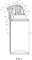
- the first part, generally designated A, is a shroud which is adapted to be attached to the top of an aerosol container over the valve stem, as shown in Figure 2 .
- the second part is an actuation member which is moveably mounted within shroud A for movement relative to the shroud between a first position wherein the stem is not depressed and a second position wherein the stem is depressed by the application of an external force on a surface of the first part which is aligned with the stem.
- the second part includes a nozzle at the front end with at least one outlet port.
- the body of actuation member B includes a conduit connecting the stem and the nozzle. When the pressurized fluid contents of the container are released from the depressed stem, the contents pass through the conduit to the nozzle. From the nozzle, the fluid exits the outlet port in a spray pattern determined by the size and shape of the outlet port.
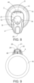
- the third part, generally designated C, is a hood which is pivotally mounted on shroud A.
- Hood C is mounted for movement between a first, blocking position in which hood C prevents actuation member B from depressing the stem and a second, unblocking position in which hood C does not prevent actuation member B from being moved to depress the stem.
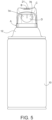
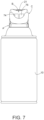
- the fourth part, generally designated D, is a locking member, best seen in Figure 5 .
- Locking member D extends from the rear portion of shroud A such that the unattached end of the locking member is normally positioned to intersect the path of movement of hood C (see Figure 2 ) such that it prevents hood C from being moved from its first blocking position in which it prevents actuation member B be from depressing the stem.
- Figures 5 and 7 show the locking member in its locked position intersecting the path of movement of hood C and in its unlocked position remote from the path of movement of hood C, respectively.
- the locking member is fabricated of resilient plastic such that it can flex such that the unattached end can move when an external force is applied to the locking member in a direction generally orthogonal to the direction of stem movement.
- locking member D is bifurcated into first and second sections.
- both of the first and second sections of the locking member must be depressed at the same time. More particularly, a substantially evenly distributed force must be applied across both of the first and second sections of the locking member to move the unattached end of the locking member to a position remote from the path of movement of the hood to permit the hood to be moved from its first blocking position toward its second unblocking position where the actuation member B can be moved to depress the stem to release the container contents.
- the direction of the external force applied to the locking member to release the hood is different than the direction of the external force applied to the actuation member surface to depress the stem. Specifically, those directions are substantially orthogonal.
- the locking member must be moved to its unlocked position by the application of substantially evenly distributed force across both of the first and second sections of the locking member.
- the hood must be moved from its first, blocking position toward its second, unblocking position.
- the actuation member must be moved toward the container by application of a downwardly directed external force applied to the top surface of the actuation member to depress the stem to release the pressurized fluid.
- the actuator of the present invention is designed for use with a container 10 of pressurized fluid.
- Container 10 has a top portion 12 with an internal valve (not shown) which is actuated by depressing a spring-loaded stem 14.
- the spring (not shown) associated with stem 14 normally urges the stem upwardly toward an extended position at which the valve is closed.
- the stem can be moved downwardly to a depressed position, against the urging of the spring, to open the valve and release the contents of the container through the stem.
- the top portion of the container includes a circular lip 16.
- the edge of the lower portion of shroud A is formed to engage lip 16 in a "snap-fit" manner to mount the actuator on the top portion 12 of the container surrounding the stem 14.
- Shroud A is hollow and includes vertically extending structural members 19a and 19b which have openings through which actuation member B extends.
- the openings are large enough to allow limited movement of the actuation member between an upper position, as seen in Figure 2 , wherein stem 14 is not depressed, and a lower position, wherein the stem is depressed.
- Actuation member B has an internal part 17 which includes a vertical portion 17a situated to engage stem 14.
- a downwardly directed external force applied to the upper surface 21 of the actuation member will cause vertical portion 17a of the actuation member to depress stem 14 to release the contents of the container.
- Stem 14 is spring-loaded such that when the external force applied on the top surface 21 of the actuation member is released, the spring will automatically move the stem to its non-depressed position, closing the valve, and the actuation member back to its upper position.
- Portion 17a is hollow and defines the vertical section of a conduit 18 which guides the fluid released from the stem to a nozzle 20.
- the other section of conduit 18 is defined by hollow portion 17b which extends horizontally from portion 17a to nozzle 20.
- Nozzle 20 is rotatably mounted between the spaced forward sections 22 and 24 of actuation member B, see Figure 1 .
- nozzle 20 has outwardly directed axle members 26 at each side which are adapted to be received within round recesses 28 in sections 22 and 24 of actuation member B.
- Nozzle 20 also has outwardly extending rectangular stop members 30 adapted to be received in arcuate channels 32 in each of the actuation member sections 22 and 24 to limit the movement of the nozzle relative to the actuation member.
- Nozzle 20 has two outlet ports 34 and 36 which are directed at right angles to each other. Port 34 is adapted to receive a spray pattern defining member 38. Member 38 causes the fluid released from the container to exit in a wide spray pattern when the nozzle is in the position illustrated in Figure 2 such that port 34 is connected to conduit 18. In that position of the nozzle, there is no fluid connection between conduit 18 and port 36 and fluid from the container cannot exit through port 36.
- Port 36 is elongated and adapted to receive the end of a flexible tube 40.
- Tube 40 can be configured as necessary to direct the fluid to a specific target without depositing in areas where it is not needed.
- the nozzle When the nozzle is in the position shown in Figure 6 , fluid from conduit 18 travels through port 36 into tube 40 and exits through the unattached end of tube 40 in a narrow spray pattern. Accordingly, the pattern in which the released fluid is sprayed is determined by the rotational position of the nozzle.
- a rubber sealing ring 42 is situated between the end of conduit 18 and nozzle 20 to prevent leakage.
- hood C includes a top surface 44 and spaced side portions 46 and 48. Protruding inwardly from each of the interior surfaces of side portions 46 and 48 are axle protrusions 50, 52, respectively. Protrusions 50, 52 are adapted to be received in openings 54 in shroud C such that hood C can rotate between its first blocking position ( Figure 4 ) and its second unblocking position ( Figure 6 ).
- the upper rear portion 56 of shroud A extending between axle receiving openings 54, is recessed relative to the remained of the exterior of the shroud by a distance approximately equal to the thickness of hood C. Accordingly, the exterior surface of the hood is substantially co-extensive with the exterior surface of the remainder of the shroud.
- the sides 46, 48 of the hood each have a forwardly extending rounded protrusion 58, 60, respectively.
- Each of the sides 62, 64 of the shroud have a recess or indentation 66 in the upper rear corner of the side, as best seen in Figure 4 .
- Protrusions 58, 60 are situated on the hood such that they can extend into recesses 66 when the hood is in the first, blocking position.
- the top surface 68 of actuation member B has outwardly extending rectangular shaped protrusions 70, 72.
- Protrusions 70, 72 also extend into recesses 66.
- Protrusions 70, 72 move up and down within recesses 66 as the actuation member moves within the shroud between its position in which stem 14 is not depressed and its position in which the stem is depressed.
- protrusions 58, 60 of the hood are situated beneath protrusions 70, 72 of the actuation member in recesses 66. In that position of the hood, the hood protrusions block the actuation member protrusions from moving downwardly in the recesses. That in turn prevents the actuation member from being moved toward the container to depress the stem and release the contents of the container.
- nozzle 20 is rotatably mounted on the front end of the actuation member.
- the accidental release of fluid in such circumstance is prevented by the hood in its blocking position, because protrusions 58, 60 of the hood prevent protrusions 70, 72 of the actuation member from moving downward within recesses 66.
- the hood protrusions 58, 60 are no longer situated in recesses 66.
- the actuation member B protrusions 70, 72 are no longer prevented from moving down within recesses 66 toward the container. In that position, the hood does not prevent the application of an external force on the on surface 68 of the actuation member from moving the actuation member toward the container to depress the stem and release the contents of the container.
- Hood protrusions 58, 60 are rounded.
- the arcuate surfaces of the protrusions serve to cam the actuation member protrusions upwardly out of the way of the hood protrusions as the hood is moved from its second, unblocking position toward its first, blocking position such that the hood protrusions can be received beneath the actuation member protrusions in order to prevent an external downward force on the actuation member from causing the actuation member to depress the stem.
- the rubber sealing ring 42 creates a fluid tight connection between the end of conduit 18 of the actuation member and the nozzle 20.
- the hood cannot move from its first, blocking position toward its second, unblocking position until the locking member D is released by moving the unattached end of the locking member D out of the path of movement of the hood.
- Locking member D is flexible and the unattached end of the locking member can be moved out of the path of hood movement by the application of an external force in a direction which is substantially orthogonal to the direction of the force which must be applied to the actuation member to depress the stem, see the arrows in Figure 2 .
- Locking member D has two coplanar spaced sections 74, 76. Both sections of the locking member must be simultaneously depressed such that the unattached ends thereof move from their position intersecting the path of hood movement, inwardly of the hood ( Figures 2 and 5 ), to a position remote from the hood path ( Figure 7 ), thereby allowing the hood C to move away from its first, blocking position.
- a substantially evenly distributed force must be applied across both of the sections 74, 76 of the locking member to cause the unattached ends of the locking member sections to move to a position remote from the path of movement of the hood and thus to permit the hood to be moved from its first, blocking position such that the actuation member B can be moved to depress the stem to release the contents of the container.
- the actuation member also acts as a stop, limiting the distance which the unattached ends of the sections of the locking member can be pushed toward the interior of the shroud.
- the rear portion of the actuation member has a vertically extending wall which is aligned with but normally spaced a short distance from the unattached ends of the locking member sections.
Landscapes
- Engineering & Computer Science (AREA)
- Mechanical Engineering (AREA)
- Chemical & Material Sciences (AREA)
- Dispersion Chemistry (AREA)
- Containers And Packaging Bodies Having A Special Means To Remove Contents (AREA)
- Nozzles (AREA)
Claims (14)
- Kindersicherer Aerosolbetätiger zur Verwendung mit einem Behälter (10) mit unter Druck stehendem Fluid des Typs, der ein Ventil mit einem Schaft (14) aufweist, der drückbar ist, um den Inhalt des Behälters (10) freizugeben, wobei der Betätiger Folgendes umfasst: eine Abdeckung (A), die ausgelegt ist, um sich auf dem Behälter (10) über dem Schaft (14) zu befinden, ein Betätigungselement (B), das eine Oberfläche (21) aufweist und an der Abdeckung (A) für Bewegung relativ zu der Abdeckung (A) zwischen einer ersten Position, wobei der Schaft (14) nicht gedrückt ist, und einer zweiten Position, wobei der Schaft (14) gedrückt ist, um den Inhalt des Behälters (10) freizugeben, montiert ist, wobei das Betätigungselement (B) eine Düse (20) und eine Leitung (18), die den Schaft (14) und die Düse (20) verbindet, eine manuell bewegbare Haube (C), die eine normale Position aufweist, um zu verhindern, dass das Betätigungselement (B) von der ersten Position zu der zweiten Position bewegt wird, und ein Verriegelungselement (D), das sich von der Abdeckung (A) zu einer Position erstreckt, die den Bewegungsweg der Haube in ihrer normalen Position schneidet, sodass sich die Haube nicht von ihrer normalen Position bewegen kann, wodurch verhindert wird, dass das Betätigungselement den Schaft drückt, beinhaltet, wobei das Verriegelungselement (D) zu einer Position entfernt von einem Haubenbewegungsweg bewegbar ist, sodass die Haube von ihrer normalen Position bewegt werden kann, wobei das Betätigungselement (B) nicht mehr daran gehindert wird, zu der zweiten Position durch eine externe Kraft, die auf die Betätigungselementoberfläche (21) ausgeübt wird, bewegt zu werden, wobei das Verriegelungselement (D) ein loses Ende umfasst, das normalerweise positioniert ist, um den Bewegungsweg der Haube (C) zu schneiden, wodurch normalerweise verhindert wird, dass die Haube (C) von ihrer normalen Position bewegt wird, wobei bei Ausübung einer externen Kraft auf das Verriegelungselement (D) in einer Richtung, die im Allgemeinen zu dem Schaft und im Wesentlichen orthogonal zu der Richtung der Schaftbewegung ist, bewirkt wird, dass sich das lose Ende des Verriegelungselements (D) zu der Position entfernt von dem Bewegungsweg der Haube (C) bewegt, sodass die Haube (C) zu einer Entblockungsposition bewegt werden kann, wobei das Betätigungselement (B) zu der zweiten Position durch die Ausübung der externen Kraft auf die Betätigungselementoberfläche (21) bewegt werden kann, um den Schaft (14) zu drücken.
- Betätiger nach Anspruch 1, wobei das Verriegelungselement (D) flexibel ist und durch die Ausübung von externer Kraft auf das Verriegelungselement (D) von der weiteren Position, die den Bewegungsweg der Haube (C) schneidet, zu der Position entfernt von dem Haubenbewegungsweg bewegt werden kann.
- Betätiger nach Anspruch 1, wobei das Verriegelungselement (D) flexibel ist und zwei koplanare Abschnitte (74, 76) jeweils mit einem losen Ende umfasst, wobei die losen Enden normalerweise positioniert sind, um den Bewegungsweg der Haube (C) zu schneiden, wobei beide gleichzeitig aus dem Haubenbewegungsweg bewegt werden müssen, um zu ermöglichen, dass die Haube (C) von ihrer normalen Position bewegt wird, wodurch verhindert wird, dass das Betätigungselement (B) den Schaft (14) drückt, wobei optional im Wesentlichen gleichmäßig verteilte externe Kraft auf beide Abschnitte (74, 76) des Verriegelungselements (D) ausgeübt werden muss, um die Abschnitte (74, 76) des Verriegelungselements (D) aus dem Haubenbewegungsweg zu bewegen.
- Betätiger nach Anspruch 1, wobei die Abdeckung (A) eine erste und eine zweite beabstandete gegenüberliegende Seite (62, 64) umfasst und wobei die Haube eine erste und eine zweite Seite (46, 48) umfasst, die jeweils eine Innenoberfläche aufweisen und Vorsprünge (50, 52) aufweisen, die von jeder der Innenoberflächen nach innen vorspringen, wobei die Vorsprünge (50, 52) ausgelegt sind, um in Öffnungen (54) in der Abdeckung (A) aufgenommen zu werden, sodass die Haube (C) schwenkbar jeweils mit der ersten und der zweiten beabstandeten gegenüberliegenden Seite (62, 64) der Abdeckung (A) verbunden ist.
- Betätiger nach Anspruch 1, wobei die Haube (C) im Allgemeinen "U"-förmig ist.
- Betätiger nach Anspruch 1, wobei der Schaft (14) einen oberen Teil (12) umfasst, wobei der Schaft (14) mit einer Feder assoziiert ist, wobei die Feder den Schaft (14) normalerweise zu einer ausgefahrenen Position drängt, um das Ventil zu schließen, wobei der Schaft (14) zu einer gedrückten Position gegen das Drängen der Feder bewegt werden kann, um das Ventil zu öffnen und den Inhalt des Behälters (10) freizugeben, wobei die Abdeckung (A) ausgelegt ist, um sich über dem oberen Teil des Behälters (10) zu befinden, der den Schaft (14) umgibt.
- Betätiger nach Anspruch 1, wobei die Abdeckung (A) einen vorderen und einen hinteren Teil umfasst, wobei der vordere Teil zu der Düse (20) angeordnet ist und der hintere Teil der Abdeckung (A) das Verriegelungselement (D) umfasst, das sich normalerweise befindet, um zu verhindern, dass die Haube (C) von ihrer normalen Position bewegt wird, wobei das Verriegelungselement (D) zu der Position entfernt von dem Bewegungsweg der Haube (C) bewegbar ist, sodass die Haube (C) von der normalen Position bewegt werden kann.
- Betätiger nach Anspruch 1, wobei die Abdeckung (A) Aussparungen (66) umfasst und das Betätigungselement (B) Anteile (70, 72) umfasst, die ausgelegt sind, um sich in die Abdeckungsaussparungen (66) zu erstrecken und sich innerhalb dieser zu bewegen, zwischen einer Position, wobei das Betätigungselement (B) bewegt werden kann, um den Schaft (14) zu drücken, und einer Position, wobei verhindert wird, dass das Betätigungselement (B) bewegt wird, um den Schaft (14) zu drücken, wobei optional das Betätigungselement (B) die Bewegung des Verriegelungselements (D) zu der Position begrenzt, wobei die Haube (C) bewegt werden kann.
- Betätiger nach Anspruch 8, wobei die Haube (C) Anteile (58, 60) umfasst, die ausgelegt sind, um sich in die Abdeckungsaussparungen (66) zu erstrecken, um zu blockieren, dass sich die Betätigungselementanteile (70, 72) innerhalb der Abdeckungsaussparungen (66) bewegen, wenn die Haube (C) in ihrer normalen Position ist.
- Betätiger nach Anspruch 9, wobei die Haube (C) zu einer Entblockungsposition bewegbar ist, wobei die Haubenanteile (58, 60) entfernt von den Abdeckungsaussparungen (66) sind, sodass die Betätigungselementanteile (70, 72) innerhalb der Abdeckungsaussparungen (66) bewegt werden können, sodass das Betätigungselement (B) bewegt werden kann, um den Schaft (14) zu drücken.
- Betätiger nach Anspruch 1, wobei die Düse zur Bewegung relativ zu dem Betätigungselement (B) montiert ist und wobei die Haube (C) die versehentliche Freigabe des Inhalts des Behälters (10) verhindert, die aus Bewegung der Düse (20) resultiert.
- Betätiger nach Anspruch 1, wobei das Betätigungselement (B) bewegbar ist, um den Schaft (14) zu drücken, indem die externe Kraft auf die Betätigungselementoberfläche (21) in einer Richtung aufgebracht wird, die im Allgemeinen parallel zu der Richtung der Schaftbewegung ist, und wobei das Verriegelungselement (D) zu einer weiteren Position entfernt von der Position bewegt wird, indem eine Kraft auf das Verriegelungselement (D) in einer Richtung aufgebracht wird, die im Allgemeinen zu dem Schaft und im Wesentlichen orthogonal zu der Richtung der Schaftbewegung ist.
- Betätiger nach Anspruch 1, wobei die Abdeckung (A) ferner einen vorderen und einen hinteren Teil umfasst, wobei die Düse (20) schwenkbar an dem Betätigungselement (B) montiert ist und sich von dem vorderen Teil der Abdeckung (A) erstreckt, wobei sich das Verriegelungselement (D) von der Abdeckung (A) an dem hinteren Teil der Abdeckung erstreckt.
- Betätiger nach Anspruch 1, wobei die Haube (C) das Verriegelungselement (D) zumindest teilweise abdeckt, wenn die Haube (C) von ihrer normalen Position bewegt wird.
Applications Claiming Priority (3)
| Application Number | Priority Date | Filing Date | Title |
|---|---|---|---|
| US15/701,558 US10370176B2 (en) | 2017-09-12 | 2017-09-12 | Child resistant aerosol actuator |
| EP18857058.4A EP3681819B1 (de) | 2017-09-12 | 2018-09-11 | Kindersicherer aerosolbetätiger |
| PCT/US2018/050424 WO2019055395A1 (en) | 2017-09-12 | 2018-09-11 | CHILD SAFETY AEROSOL ACTUATOR |
Related Parent Applications (2)
| Application Number | Title | Priority Date | Filing Date |
|---|---|---|---|
| EP18857058.4A Division-Into EP3681819B1 (de) | 2017-09-12 | 2018-09-11 | Kindersicherer aerosolbetätiger |
| EP18857058.4A Division EP3681819B1 (de) | 2017-09-12 | 2018-09-11 | Kindersicherer aerosolbetätiger |
Publications (2)
| Publication Number | Publication Date |
|---|---|
| EP4043363A1 EP4043363A1 (de) | 2022-08-17 |
| EP4043363B1 true EP4043363B1 (de) | 2025-07-09 |
Family
ID=65630513
Family Applications (2)
| Application Number | Title | Priority Date | Filing Date |
|---|---|---|---|
| EP18857058.4A Active EP3681819B1 (de) | 2017-09-12 | 2018-09-11 | Kindersicherer aerosolbetätiger |
| EP22154362.2A Active EP4043363B1 (de) | 2017-09-12 | 2018-09-11 | Kindersicherer aerosolbetätiger |
Family Applications Before (1)
| Application Number | Title | Priority Date | Filing Date |
|---|---|---|---|
| EP18857058.4A Active EP3681819B1 (de) | 2017-09-12 | 2018-09-11 | Kindersicherer aerosolbetätiger |
Country Status (12)
| Country | Link |
|---|---|
| US (2) | US10370176B2 (de) |
| EP (2) | EP3681819B1 (de) |
| JP (1) | JP2020533248A (de) |
| CN (1) | CN111356643B (de) |
| AU (1) | AU2018334523A1 (de) |
| BR (1) | BR112020004895A2 (de) |
| CA (1) | CA3075536C (de) |
| ES (2) | ES3042189T3 (de) |
| PL (2) | PL3681819T3 (de) |
| RU (1) | RU2745167C1 (de) |
| TW (2) | TWI680938B (de) |
| WO (1) | WO2019055395A1 (de) |
Families Citing this family (7)
| Publication number | Priority date | Publication date | Assignee | Title |
|---|---|---|---|---|
| US10464736B1 (en) * | 2017-09-21 | 2019-11-05 | The B'Laster Corporation | Spray can actuator |
| USD907491S1 (en) * | 2018-09-21 | 2021-01-12 | B'laster Llc | Spray can actuator |
| USD929229S1 (en) | 2018-09-21 | 2021-08-31 | B'laster Llc | Spray can actuator |
| US11370600B1 (en) | 2018-09-21 | 2022-06-28 | B'laster Llc. | Spray can actuator |
| DE102019220036A1 (de) * | 2019-12-18 | 2021-06-24 | Henkel Ag & Co. Kgaa | Ausgabesystem für einen Behälter |
| US20220396414A1 (en) * | 2021-06-10 | 2022-12-15 | Dap Products Inc. | Texture material dispensing system including an adjustable outlet opening |
| US11794199B2 (en) | 2022-01-20 | 2023-10-24 | Packaging Concepts Associates Holding, Inc. | Folding extension nozzle and dispensing assembly |
Family Cites Families (45)
| Publication number | Priority date | Publication date | Assignee | Title |
|---|---|---|---|---|
| US2646192A (en) | 1952-11-05 | 1953-07-21 | Owens Illinois Glass Co | Pressure type container |
| US3169672A (en) * | 1963-01-23 | 1965-02-16 | Clayton Corp Of Delaware | Locking actuator cap for valved dispenser |
| US3622052A (en) * | 1969-12-01 | 1971-11-23 | Sunbeam Plastics Corp | Childproof dispensing valve actuator for an aerosol can |
| US3744682A (en) * | 1971-09-01 | 1973-07-10 | Dow Chemical Co | Safety overcap for aerosol containers |
| US4895190A (en) * | 1987-03-09 | 1990-01-23 | Airosol Company, Inc. | Actuator and hose assembly for aerosol containers |
| US4941600A (en) * | 1989-08-31 | 1990-07-17 | Technical Chemical Company | Dispenser lock assembly for a pressurized container |
| JPH06134357A (ja) * | 1992-10-22 | 1994-05-17 | Tooa Eiyoo Kk | 噴霧装置 |
| SE501782C2 (sv) * | 1993-09-17 | 1995-05-15 | Flaekt Ab | Sätt och anordning för att selektivt avlägsna svavelväte från en gas |
| JPH11278566A (ja) * | 1998-03-31 | 1999-10-12 | Yoshino Kogyosho Co Ltd | エアゾール式噴出容器 |
| US6257233B1 (en) | 1998-06-04 | 2001-07-10 | Inhale Therapeutic Systems | Dry powder dispersing apparatus and methods for their use |
| EP1078868A4 (de) | 1999-01-18 | 2009-03-04 | Earth Chemical Co | Betätigungsvorrichtung für aerosolbehälter |
| JP2001088877A (ja) * | 1999-09-16 | 2001-04-03 | Paio:Kk | エアゾール容器 |
| GB0003343D0 (en) * | 2000-02-14 | 2000-04-05 | Unilever Plc | Actuator mechanism |
| US20020000225A1 (en) | 2000-06-02 | 2002-01-03 | Carlos Schuler | Lockout mechanism for aerosol drug delivery devices |
| US6394364B1 (en) | 2000-09-29 | 2002-05-28 | Robert Henry Abplanalp | Aerosol spray dispenser |
| US6286728B1 (en) * | 2001-01-05 | 2001-09-11 | Saint-Gobain Calmar Inc. | Shroud cover for trigger sprayer |
| US6382469B1 (en) * | 2001-07-31 | 2002-05-07 | Precision Thermoplastic Components, Inc. | Tire inflation actuator |
| US6691896B2 (en) | 2001-08-21 | 2004-02-17 | Dispensing Patents International, Llc | Safety closure for a container |
| US7070069B2 (en) | 2002-03-07 | 2006-07-04 | Connetics Corporation | Aerosol system having lockable cap |
| US6854619B2 (en) | 2002-10-18 | 2005-02-15 | Summit Packaging Systems, Inc. | Flip-top closure with child resistant packaging system |
| US8100298B2 (en) | 2003-03-03 | 2012-01-24 | Aptargroup, Inc. | Aerosol actuator |
| US20050061014A1 (en) * | 2003-09-22 | 2005-03-24 | George Cannan | Extension for top of refrigerant can for dispensing without a valve |
| DE102004022131A1 (de) | 2004-05-05 | 2005-11-24 | Boehringer Ingelheim Microparts Gmbh | Sprühkopf zum Atomisieren eines Mediums |
| US7922041B2 (en) * | 2005-12-29 | 2011-04-12 | The Procter & Gamble Company | Spray dispensers |
| US7530476B2 (en) * | 2006-04-10 | 2009-05-12 | Precision Valve Corporation | Locking aerosol dispenser |
| US7588171B2 (en) | 2006-09-12 | 2009-09-15 | Masterchem Industries Llc | Actuator for an aerosol container |
| US7699190B2 (en) * | 2007-01-04 | 2010-04-20 | Precision Valve Corporation | Locking aerosol dispenser |
| FR2924097A1 (fr) * | 2007-03-26 | 2009-05-29 | Lindal France Soc Par Actions | Capuchon pour pulverisateur. |
| US20080290120A1 (en) | 2007-05-25 | 2008-11-27 | Helf Thomas A | Actuator cap for a spray device |
| US20080290113A1 (en) | 2007-05-25 | 2008-11-27 | Helf Thomas A | Actuator cap for a spray device |
| US20090242502A1 (en) * | 2008-03-28 | 2009-10-01 | Jack Jie Qin | Flip-cap arrangement for container |
| ITRM20080186A1 (it) * | 2008-04-09 | 2009-10-10 | Emsar Spa | Tappo di protezione per erogatori e contenitore comprendente tale tappo. |
| WO2010056724A1 (en) * | 2008-11-12 | 2010-05-20 | Meadwestvaco Calmar, Inc. | Spray devices and methods for using the same |
| US8540121B2 (en) * | 2009-07-07 | 2013-09-24 | Aptargroup, Inc. | Dispensing actuator with flip-open lid |
| EP2551214A4 (de) * | 2010-03-12 | 2017-12-27 | Mitani Valve Co., Ltd. | Behälterabdeckung und aerosolprodukt mit der behälterabdeckung |
| MX2012012847A (es) * | 2010-05-05 | 2012-11-30 | Unilever Nv | Accionador para un recipiente de aerosol. |
| JP2012062090A (ja) * | 2010-09-16 | 2012-03-29 | Kissho:Kk | スプレー容器のノズル安全装置 |
| CN202173166U (zh) * | 2011-08-04 | 2012-03-28 | 佛山市南海育成婴儿用品有限公司 | 一种双层防漏吸水杯 |
| US8777061B1 (en) | 2012-03-03 | 2014-07-15 | Emil Meshberg | Safety closure for container |
| FR2998557B1 (fr) | 2012-11-27 | 2015-12-11 | Technima | Generateur aerosol a poignee amovible et dispositif d'interdiction de manoeuvre |
| JP6151575B2 (ja) | 2013-05-31 | 2017-06-21 | 東洋エアゾール工業株式会社 | エアゾール容器用ノズル及びエアゾール容器用吐出具 |
| FR3007299B1 (fr) * | 2013-06-24 | 2015-11-27 | Lindal France | Diffuseur |
| CA2919867A1 (en) * | 2013-07-31 | 2015-02-05 | Msd Consumer Care, Inc. | Oversized actuator and actuator assembly for a pressurized plastic vessel |
| AP2016009486A0 (en) | 2014-05-07 | 2016-10-31 | Boehringer Ingelheim Int | Nebulizer, indicator device and container |
| JP2017137085A (ja) * | 2016-02-03 | 2017-08-10 | ホーユー株式会社 | 保護キャップ付き複数剤吐出容器 |
-
2017
- 2017-09-12 US US15/701,558 patent/US10370176B2/en active Active
-
2018
- 2018-09-11 JP JP2020536725A patent/JP2020533248A/ja not_active Ceased
- 2018-09-11 RU RU2020115050A patent/RU2745167C1/ru active
- 2018-09-11 EP EP18857058.4A patent/EP3681819B1/de active Active
- 2018-09-11 EP EP22154362.2A patent/EP4043363B1/de active Active
- 2018-09-11 PL PL18857058.4T patent/PL3681819T3/pl unknown
- 2018-09-11 CN CN201880072968.1A patent/CN111356643B/zh active Active
- 2018-09-11 ES ES22154362T patent/ES3042189T3/es active Active
- 2018-09-11 BR BR112020004895-0A patent/BR112020004895A2/pt not_active Application Discontinuation
- 2018-09-11 ES ES18857058T patent/ES3052997T3/es active Active
- 2018-09-11 AU AU2018334523A patent/AU2018334523A1/en not_active Abandoned
- 2018-09-11 WO PCT/US2018/050424 patent/WO2019055395A1/en not_active Ceased
- 2018-09-11 PL PL22154362.2T patent/PL4043363T3/pl unknown
- 2018-09-11 CA CA3075536A patent/CA3075536C/en active Active
- 2018-09-12 TW TW107132019A patent/TWI680938B/zh active
- 2018-09-12 TW TW108145756A patent/TWI716223B/zh active
- 2018-12-21 US US16/229,914 patent/US10752427B2/en active Active
Also Published As
| Publication number | Publication date |
|---|---|
| EP3681819B1 (de) | 2025-10-29 |
| TWI716223B (zh) | 2021-01-11 |
| RU2745167C1 (ru) | 2021-03-22 |
| BR112020004895A2 (pt) | 2020-09-15 |
| EP3681819A1 (de) | 2020-07-22 |
| US20190119031A1 (en) | 2019-04-25 |
| JP2020533248A (ja) | 2020-11-19 |
| TWI680938B (zh) | 2020-01-01 |
| ES3042189T3 (en) | 2025-11-19 |
| EP4043363A1 (de) | 2022-08-17 |
| WO2019055395A8 (en) | 2020-03-26 |
| US10370176B2 (en) | 2019-08-06 |
| CN111356643B (zh) | 2022-05-10 |
| PL3681819T3 (pl) | 2026-01-26 |
| CA3075536A1 (en) | 2019-03-21 |
| AU2018334523A1 (en) | 2020-06-04 |
| WO2019055395A1 (en) | 2019-03-21 |
| ES3052997T3 (en) | 2026-01-16 |
| TW202016007A (zh) | 2020-05-01 |
| US20190077580A1 (en) | 2019-03-14 |
| TW201919984A (zh) | 2019-06-01 |
| CN111356643A (zh) | 2020-06-30 |
| CA3075536C (en) | 2022-03-29 |
| PL4043363T3 (pl) | 2025-11-24 |
| EP3681819A4 (de) | 2021-06-16 |
| US10752427B2 (en) | 2020-08-25 |
Similar Documents
| Publication | Publication Date | Title |
|---|---|---|
| EP4043363B1 (de) | Kindersicherer aerosolbetätiger | |
| EP1915299B1 (de) | Sprühaktuator | |
| US4024988A (en) | Safety closure assembly for an aerosol container | |
| US8622256B2 (en) | Actuator for spray container with restraint structure | |
| US20120187151A1 (en) | Child resistant container with inverting cap top key for spray activation | |
| US9227027B2 (en) | Three-point child resistant lid | |
| US4428509A (en) | Dispensing device for continuous aerosol | |
| US3754689A (en) | Safety overcap for aerosol containers | |
| US8544664B2 (en) | Child resistant container with inverting cap bottom lift | |
| US3924782A (en) | Safety closure assembly for capping a dispensing container | |
| HK40079859A (en) | Child resistant aerosol actuator | |
| HK40022711A (en) | Child resistant aerosol actuator | |
| HK40022711B (zh) | 儿童安全的气雾剂致动器 |
Legal Events
| Date | Code | Title | Description |
|---|---|---|---|
| PUAI | Public reference made under article 153(3) epc to a published international application that has entered the european phase |
Free format text: ORIGINAL CODE: 0009012 |
|
| STAA | Information on the status of an ep patent application or granted ep patent |
Free format text: STATUS: THE APPLICATION HAS BEEN PUBLISHED |
|
| AC | Divisional application: reference to earlier application |
Ref document number: 3681819 Country of ref document: EP Kind code of ref document: P |
|
| AK | Designated contracting states |
Kind code of ref document: A1 Designated state(s): AL AT BE BG CH CY CZ DE DK EE ES FI FR GB GR HR HU IE IS IT LI LT LU LV MC MK MT NL NO PL PT RO RS SE SI SK SM TR |
|
| STAA | Information on the status of an ep patent application or granted ep patent |
Free format text: STATUS: REQUEST FOR EXAMINATION WAS MADE |
|
| 17P | Request for examination filed |
Effective date: 20230217 |
|
| RBV | Designated contracting states (corrected) |
Designated state(s): AL AT BE BG CH CY CZ DE DK EE ES FI FR GB GR HR HU IE IS IT LI LT LU LV MC MK MT NL NO PL PT RO RS SE SI SK SM TR |
|
| REG | Reference to a national code |
Ref country code: HK Ref legal event code: DE Ref document number: 40079859 Country of ref document: HK |
|
| GRAP | Despatch of communication of intention to grant a patent |
Free format text: ORIGINAL CODE: EPIDOSNIGR1 |
|
| STAA | Information on the status of an ep patent application or granted ep patent |
Free format text: STATUS: GRANT OF PATENT IS INTENDED |
|
| RIC1 | Information provided on ipc code assigned before grant |
Ipc: B65D 83/303 20250101ALI20250109BHEP Ipc: B65D 83/22 20060101ALI20250109BHEP Ipc: B65D 83/24 20060101ALI20250109BHEP Ipc: B65D 83/30 20060101ALI20250109BHEP Ipc: B65D 50/04 20060101ALI20250109BHEP Ipc: B05B 11/00 20060101ALI20250109BHEP Ipc: B05B 1/16 20060101ALI20250109BHEP Ipc: B65D 83/20 20060101AFI20250109BHEP |
|
| INTG | Intention to grant announced |
Effective date: 20250204 |
|
| GRAS | Grant fee paid |
Free format text: ORIGINAL CODE: EPIDOSNIGR3 |
|
| GRAA | (expected) grant |
Free format text: ORIGINAL CODE: 0009210 |
|
| STAA | Information on the status of an ep patent application or granted ep patent |
Free format text: STATUS: THE PATENT HAS BEEN GRANTED |
|
| AC | Divisional application: reference to earlier application |
Ref document number: 3681819 Country of ref document: EP Kind code of ref document: P |
|
| AK | Designated contracting states |
Kind code of ref document: B1 Designated state(s): AL AT BE BG CH CY CZ DE DK EE ES FI FR GB GR HR HU IE IS IT LI LT LU LV MC MK MT NL NO PL PT RO RS SE SI SK SM TR |
|
| REG | Reference to a national code |
Ref country code: GB Ref legal event code: FG4D |
|
| REG | Reference to a national code |
Ref country code: CH Ref legal event code: EP |
|
| REG | Reference to a national code |
Ref country code: IE Ref legal event code: FG4D |
|
| REG | Reference to a national code |
Ref country code: DE Ref legal event code: R096 Ref document number: 602018083540 Country of ref document: DE |
|
| REG | Reference to a national code |
Ref country code: CH Ref legal event code: PK Free format text: BERICHTIGUNGEN |
|
| P01 | Opt-out of the competence of the unified patent court (upc) registered |
Free format text: CASE NUMBER: UPC_APP_3201_4043363/2025 Effective date: 20250812 |
|
| RIN2 | Information on inventor provided after grant (corrected) |
Inventor name: STARZMAN, MICHAEL J. Inventor name: FREUDENBERG, JOHN W. Inventor name: BATES, KEVIN VICTOR Inventor name: KRUPP, BENJAMIN THOMAS Inventor name: STATES III, ROBERT GERALD Inventor name: PARROT, DAVID A. Inventor name: GOOD, ROBERT J. Inventor name: DODD, JOSEPH K. Inventor name: FALCON, SARA DAWSON |
|
| PGFP | Annual fee paid to national office [announced via postgrant information from national office to epo] |
Ref country code: DE Payment date: 20250919 Year of fee payment: 8 |
|
| PGFP | Annual fee paid to national office [announced via postgrant information from national office to epo] |
Ref country code: GB Payment date: 20250919 Year of fee payment: 8 |
|
| PGFP | Annual fee paid to national office [announced via postgrant information from national office to epo] |
Ref country code: FR Payment date: 20250922 Year of fee payment: 8 |
|
| REG | Reference to a national code |
Ref country code: NL Ref legal event code: MP Effective date: 20250709 |
|
| REG | Reference to a national code |
Ref country code: ES Ref legal event code: FG2A Ref document number: 3042189 Country of ref document: ES Kind code of ref document: T3 Effective date: 20251119 |
|
| PG25 | Lapsed in a contracting state [announced via postgrant information from national office to epo] |
Ref country code: PT Free format text: LAPSE BECAUSE OF FAILURE TO SUBMIT A TRANSLATION OF THE DESCRIPTION OR TO PAY THE FEE WITHIN THE PRESCRIBED TIME-LIMIT Effective date: 20251110 |
|
| PG25 | Lapsed in a contracting state [announced via postgrant information from national office to epo] |
Ref country code: NL Free format text: LAPSE BECAUSE OF FAILURE TO SUBMIT A TRANSLATION OF THE DESCRIPTION OR TO PAY THE FEE WITHIN THE PRESCRIBED TIME-LIMIT Effective date: 20250709 |
|
| REG | Reference to a national code |
Ref country code: AT Ref legal event code: MK05 Ref document number: 1811688 Country of ref document: AT Kind code of ref document: T Effective date: 20250709 |
|
| PG25 | Lapsed in a contracting state [announced via postgrant information from national office to epo] |
Ref country code: IS Free format text: LAPSE BECAUSE OF FAILURE TO SUBMIT A TRANSLATION OF THE DESCRIPTION OR TO PAY THE FEE WITHIN THE PRESCRIBED TIME-LIMIT Effective date: 20251109 |
|
| PG25 | Lapsed in a contracting state [announced via postgrant information from national office to epo] |
Ref country code: NO Free format text: LAPSE BECAUSE OF FAILURE TO SUBMIT A TRANSLATION OF THE DESCRIPTION OR TO PAY THE FEE WITHIN THE PRESCRIBED TIME-LIMIT Effective date: 20251009 |
|
| REG | Reference to a national code |
Ref country code: LT Ref legal event code: MG9D |
|
| PG25 | Lapsed in a contracting state [announced via postgrant information from national office to epo] |
Ref country code: AT Free format text: LAPSE BECAUSE OF FAILURE TO SUBMIT A TRANSLATION OF THE DESCRIPTION OR TO PAY THE FEE WITHIN THE PRESCRIBED TIME-LIMIT Effective date: 20250709 |
|
| PG25 | Lapsed in a contracting state [announced via postgrant information from national office to epo] |
Ref country code: FI Free format text: LAPSE BECAUSE OF FAILURE TO SUBMIT A TRANSLATION OF THE DESCRIPTION OR TO PAY THE FEE WITHIN THE PRESCRIBED TIME-LIMIT Effective date: 20250709 |
|
| PGFP | Annual fee paid to national office [announced via postgrant information from national office to epo] |
Ref country code: IT Payment date: 20251030 Year of fee payment: 8 |
|
| PG25 | Lapsed in a contracting state [announced via postgrant information from national office to epo] |
Ref country code: HR Free format text: LAPSE BECAUSE OF FAILURE TO SUBMIT A TRANSLATION OF THE DESCRIPTION OR TO PAY THE FEE WITHIN THE PRESCRIBED TIME-LIMIT Effective date: 20250709 |
|
| PG25 | Lapsed in a contracting state [announced via postgrant information from national office to epo] |
Ref country code: GR Free format text: LAPSE BECAUSE OF FAILURE TO SUBMIT A TRANSLATION OF THE DESCRIPTION OR TO PAY THE FEE WITHIN THE PRESCRIBED TIME-LIMIT Effective date: 20251010 |
|
| PG25 | Lapsed in a contracting state [announced via postgrant information from national office to epo] |
Ref country code: SE Free format text: LAPSE BECAUSE OF FAILURE TO SUBMIT A TRANSLATION OF THE DESCRIPTION OR TO PAY THE FEE WITHIN THE PRESCRIBED TIME-LIMIT Effective date: 20250709 |
|
| PG25 | Lapsed in a contracting state [announced via postgrant information from national office to epo] |
Ref country code: LV Free format text: LAPSE BECAUSE OF FAILURE TO SUBMIT A TRANSLATION OF THE DESCRIPTION OR TO PAY THE FEE WITHIN THE PRESCRIBED TIME-LIMIT Effective date: 20250709 |
|
| PG25 | Lapsed in a contracting state [announced via postgrant information from national office to epo] |
Ref country code: BG Free format text: LAPSE BECAUSE OF FAILURE TO SUBMIT A TRANSLATION OF THE DESCRIPTION OR TO PAY THE FEE WITHIN THE PRESCRIBED TIME-LIMIT Effective date: 20250709 |
|
| PGFP | Annual fee paid to national office [announced via postgrant information from national office to epo] |
Ref country code: PL Payment date: 20250910 Year of fee payment: 8 |
|
| PG25 | Lapsed in a contracting state [announced via postgrant information from national office to epo] |
Ref country code: RS Free format text: LAPSE BECAUSE OF FAILURE TO SUBMIT A TRANSLATION OF THE DESCRIPTION OR TO PAY THE FEE WITHIN THE PRESCRIBED TIME-LIMIT Effective date: 20251009 |
|
| PGFP | Annual fee paid to national office [announced via postgrant information from national office to epo] |
Ref country code: ES Payment date: 20251030 Year of fee payment: 8 |
|
| PG25 | Lapsed in a contracting state [announced via postgrant information from national office to epo] |
Ref country code: RO Free format text: LAPSE BECAUSE OF FAILURE TO SUBMIT A TRANSLATION OF THE DESCRIPTION OR TO PAY THE FEE WITHIN THE PRESCRIBED TIME-LIMIT Effective date: 20250709 |