EP4036016B1 - System zur durchführung einer automatischen inspektion einer fluggastbrücke - Google Patents
System zur durchführung einer automatischen inspektion einer fluggastbrücke Download PDFInfo
- Publication number
- EP4036016B1 EP4036016B1 EP19946263.1A EP19946263A EP4036016B1 EP 4036016 B1 EP4036016 B1 EP 4036016B1 EP 19946263 A EP19946263 A EP 19946263A EP 4036016 B1 EP4036016 B1 EP 4036016B1
- Authority
- EP
- European Patent Office
- Prior art keywords
- operation test
- boarding bridge
- passenger boarding
- controller
- person
- Prior art date
- Legal status (The legal status is an assumption and is not a legal conclusion. Google has not performed a legal analysis and makes no representation as to the accuracy of the status listed.)
- Active
Links
Images


Classifications
-
- B—PERFORMING OPERATIONS; TRANSPORTING
- B64—AIRCRAFT; AVIATION; COSMONAUTICS
- B64F—GROUND OR AIRCRAFT-CARRIER-DECK INSTALLATIONS SPECIALLY ADAPTED FOR USE IN CONNECTION WITH AIRCRAFT; DESIGNING, MANUFACTURING, ASSEMBLING, CLEANING, MAINTAINING OR REPAIRING AIRCRAFT, NOT OTHERWISE PROVIDED FOR; HANDLING, TRANSPORTING, TESTING OR INSPECTING AIRCRAFT COMPONENTS, NOT OTHERWISE PROVIDED FOR
- B64F1/00—Ground or aircraft-carrier-deck installations
- B64F1/30—Ground or aircraft-carrier-deck installations for embarking or disembarking passengers
- B64F1/305—Bridges extending between terminal building and aircraft, e.g. telescopic, vertically adjustable
-
- G—PHYSICS
- G06—COMPUTING OR CALCULATING; COUNTING
- G06Q—INFORMATION AND COMMUNICATION TECHNOLOGY [ICT] SPECIALLY ADAPTED FOR ADMINISTRATIVE, COMMERCIAL, FINANCIAL, MANAGERIAL OR SUPERVISORY PURPOSES; SYSTEMS OR METHODS SPECIALLY ADAPTED FOR ADMINISTRATIVE, COMMERCIAL, FINANCIAL, MANAGERIAL OR SUPERVISORY PURPOSES, NOT OTHERWISE PROVIDED FOR
- G06Q10/00—Administration; Management
- G06Q10/06—Resources, workflows, human or project management; Enterprise or organisation planning; Enterprise or organisation modelling
- G06Q10/063—Operations research, analysis or management
-
- G—PHYSICS
- G06—COMPUTING OR CALCULATING; COUNTING
- G06Q—INFORMATION AND COMMUNICATION TECHNOLOGY [ICT] SPECIALLY ADAPTED FOR ADMINISTRATIVE, COMMERCIAL, FINANCIAL, MANAGERIAL OR SUPERVISORY PURPOSES; SYSTEMS OR METHODS SPECIALLY ADAPTED FOR ADMINISTRATIVE, COMMERCIAL, FINANCIAL, MANAGERIAL OR SUPERVISORY PURPOSES, NOT OTHERWISE PROVIDED FOR
- G06Q10/00—Administration; Management
- G06Q10/20—Administration of product repair or maintenance
-
- G—PHYSICS
- G06—COMPUTING OR CALCULATING; COUNTING
- G06Q—INFORMATION AND COMMUNICATION TECHNOLOGY [ICT] SPECIALLY ADAPTED FOR ADMINISTRATIVE, COMMERCIAL, FINANCIAL, MANAGERIAL OR SUPERVISORY PURPOSES; SYSTEMS OR METHODS SPECIALLY ADAPTED FOR ADMINISTRATIVE, COMMERCIAL, FINANCIAL, MANAGERIAL OR SUPERVISORY PURPOSES, NOT OTHERWISE PROVIDED FOR
- G06Q50/00—Information and communication technology [ICT] specially adapted for implementation of business processes of specific business sectors, e.g. utilities or tourism
- G06Q50/40—Business processes related to the transportation industry
-
- G—PHYSICS
- G08—SIGNALLING
- G08B—SIGNALLING SYSTEMS, e.g. PERSONAL CALLING SYSTEMS; ORDER TELEGRAPHS; ALARM SYSTEMS
- G08B21/00—Alarms responsive to a single specified undesired or abnormal condition and not otherwise provided for
- G08B21/18—Status alarms
- G08B21/22—Status alarms responsive to presence or absence of persons
Definitions
- the present invention relates to a system for performing an automatic inspection of a passenger boarding bridge.
- a passenger boarding bridge that connects between a terminal building and an aircraft is often used for boarding onto and disembarking from the aircraft.
- Patent Literature 1 discloses performing test operation of a passenger boarding bridge before docking the passenger boarding bridge with an aircraft.
- a terminal device installed in the cab of the passenger boarding bridge detects the presence or absence of abnormality in the devices of the passenger boarding bridge, and transmits data relating to abnormality to a centralized management server of a maintenance section that is in charge of the maintenance of the passenger boarding bridge.
- Patent Literature 1 does not give consideration to the aspect of coordination with persons, such as workers, when performing the test operation for an inspection of the passenger boarding bridge.
- An object of the present invention is to provide a system for performing an automatic inspection of a passenger boarding bridge, the system making it possible to efficiently perform the automatic inspection of the passenger boarding bridge in improved coordination with persons, such as workers.
- a system for performing an automatic inspection of a passenger boarding bridge is a system for performing an automatic inspection of a passenger boarding bridge in accordance with appended claim 1.
- the operation test-related information is notified inside and/or outside the passenger boarding bridge, and thereby a warning can be given inside and/or outside the passenger boarding bridge.
- the input of the inspection start command to the controller can be performed via communications, for example, by performing an inspection start operation with an external device that is located at a remote position from the passenger boarding bridge. By merely performing the inspection start operation, the automatic inspection can be carried out.
- the operation test-related information includes at least one of the following types of information: information that is notified before the start of the operation test of the first device among the devices, the information indicating that the automatic inspection is going to start; information that is notified during the automatic inspection period, the information indicating that the automatic inspection is being performed; information that is notified before the operation test of each device is performed (started), the information indicating that the operation test of the device is going to start; information that is notified while the operation test of each device is being performed, the information indicating that the operation test of the device is being performed; and information that urges a person to retreat.
- the operation test-related information may be notified in any manner, so long as the notified information is recognizable by a person, such as a worker.
- the operation test-related information may be notified, for example, in the form of verbal information outputted from a speaker, or in the form of audio information outputted from a speaker, such as particular music or a sound of a siren or the like, or in the form of light information from, for example, a revolving lamp, or any other lighting equipment, that emits light in a particular color, or in the form of characters and/or symbols displayed by a display device.
- the system may further include: a first sensor that detects a person inside the passenger boarding bridge; and a second sensor that detects a person outside the passenger boarding bridge.
- the controller may be configured to: in a case where a person is detected by the first sensor and/or the second sensor before performing the operation test of each device, cause the notifier to notify the operation test-related information that urges the person to retreat; and then perform the operation test when each of the first sensor and the second sensor detects no person any more.
- the operation test is performed when no person is detected any more both inside and outside the passenger boarding bridge. This makes it possible to perform the operation test in improved coordination with persons.
- the system may further include: a first sensor that detects a person inside the passenger boarding bridge; and a second sensor that detects a person outside the passenger boarding bridge.
- the controller may be configured to: in a case where a person is detected by the first sensor and/or the second sensor while the operation test of each device is being performed, temporarily stop the operation test and cause the notifier to notify the operation test-related information that urges the person to retreat; and then resume the operation test when each of the first sensor and the second sensor detects no person any more.
- the operation test in a case where a person is detected while the operation test is being performed, the operation test is stopped temporarily, and thereafter, when no person is detected any more, the operation test is resumed. This makes it possible to perform the operation test in improved coordination with persons.
- the controller may be configured to perform control of the device to: cause the device to operate in one direction; and then cause the device to operate in a reverse direction, such that at an end of the operation test, the device is brought back to a state that the device is in at a start of the operation test.
- the passenger boarding bridge when all the operation tests are ended (i.e., when the inspection is ended), the passenger boarding bridge is in a state that the passenger boarding bridge is in before the start of the first operation test (i.e., a state that the passenger boarding bridge is in before the start of the inspection). Accordingly, when the inspection is ended, the passenger boarding bridge is in a predetermined state at a predetermined position where the passenger boarding bridge stands by before being operated (i.e., before being docked with an aircraft). This makes it possible to smoothly perform the operation of docking the passenger boarding bridge with the aircraft when the aircraft arrives.
- the present invention is configured as described above, and has an advantage of being able to provide a system for performing an automatic inspection of a passenger boarding bridge, the system making it possible to efficiently perform the automatic inspection of the passenger boarding bridge in improved coordination with persons, such as workers.
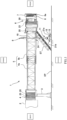
- FIG. 1 is a schematic side view showing one example of a passenger boarding bridge according to the present embodiment.
- FIG. 1 shows the passenger boarding bridge in a state where the overall length of a tunnel unit 5 thereof is extended.
- the direction in which the overall length of the tunnel unit 5 of the passenger boarding bridge 1 is extended and retracted is referred to as a front-back direction; the direction in which the gravitational force is exerted on the passenger boarding bridge 1 is referred to as a vertical direction; and the width direction of the passenger boarding bridge 1 (i.e., the direction orthogonal to the front-back direction and the vertical direction) is referred to as a left-right direction.
- the aircraft side of the passenger boarding bridge 1 is referred to as a "front" side
- the terminal building 2 side of the passenger boarding bridge 1 is referred to as a "back" side in the description below.
- the passenger boarding bridge 1 of the present embodiment includes: a rotunda (a rear round room) 4 connected to an entrance of the terminal building 2 and supported such that the rotunda 4 is rotatable about a vertical axis; the tunnel unit 5 whose proximal end is connected to the rotunda 4, the tunnel unit 5 being swingable vertically such that the distal end of the tunnel unit 5 is liftable and lowerable; a cab (a front round room) 6 rotatably provided at the distal end of the tunnel unit 5; drive columns 9 configured to support the tunnel unit 5 at the distal side of the tunnel unit 5; and auxiliary stairs ST.
- a rotunda a rear round room 4 connected to an entrance of the terminal building 2 and supported such that the rotunda 4 is rotatable about a vertical axis
- the tunnel unit 5 whose proximal end is connected to the rotunda 4, the tunnel unit 5 being swingable vertically such that the distal end of the tunnel unit 5 is liftable and lowerable
- the tunnel unit 5 forms a passenger walkway, and includes a plurality of tubular tunnels 5a and 5b, which are fitted together in a telescopic manner (nested manner), such that the tunnel unit 5 is extendable and retractable in the longitudinal direction.
- the tunnel unit 5 is formed by the two tunnels 5a and 5b as one example.
- the tunnel unit 5 is formed by two or more tunnels.
- the proximal end part of the tunnel unit 5 is connected to the rotunda 4 in such a manner that the tunnel unit 5 is liftable and lowerable (swingable vertically).
- the drive columns 9 further include a travel device 11 including a pair of travel wheels 12, which are drivable to rotate independently of each other.
- the travel device 11 is mounted below the lifting/lowering device 10.
- the travel device 11 is configured to travel forward and backward by the rotation of the two travel wheels 12, and the travel direction of the travel device 11 is changeable.
- the tunnel unit 5 can be rotated about the rotunda 4, and the tunnel unit 5 can be extended/retracted.
- the drive columns 9 may be provided not on the tunnel 5b, but on the cab 6.
- the cab 6 is provided at the distal end of the tunnel unit 5.
- the cab 6 is configured to be rotatable, by means of an unshown rotational mechanism (a cab rotator 62 shown in FIG. 4 ), in regular and reverse directions about a rotational axis that is perpendicular to the floor surface of the cab 6.
- a control board (not shown) is installed in the cab 6, and an operator can operate the passenger boarding bridge 1 by using, for example, a joystick of the control board.
- the fixed floor and the inclinable floor are coupled to each other via a coupling hinge or the like that is not shown.
- the inclinable floor equipment 61 (see FIG. 4 ) is configured to move the right end portion or the left end portion of the inclinable floor vertically with the motive force of a motor.
- the front end portion of the inclinable floor swings about the coupling hinge. Consequently, the inclinable floor is inclined in the width direction, and the front end portion of the inclinable floor can be made parallel to the surface of the apron EP.
- a part of the front end portion of the inclinable floor, the part facing the aircraft, is provided with a bumper.
- the closure 7 includes a bellows portion that is expandable and contractible in the front-back direction. At the time of docking the cab 6 with the aircraft, by expanding the bellows portion forward, the front end of the bellows portion can be brought into contact with the aircraft around the entrance thereof.
- a level detector 8 is disposed on a side wall of the cab 6.
- the level detector 8 is a device that detects the amount of upward/downward movement of the aircraft relative to the cab 6 when the aircraft moves upward/downward due to, for example, boarding/disembarking of passengers or loading/unloading of cargo after the cab 6 is docked with the entrance of the aircraft.
- the amount of upward/downward movement of the aircraft relative to the cab 6 is detected for the purpose of changing the height of the cab 6 to follow the upward/downward movement of the aircraft.
- the height of the cab 6 is changed by driving the lifting/lowering device 10.
- the level detector 8 includes a wheel 8a, which is movable forward and backward.
- the level detector 8 moves the wheel 8a forward to bring the wheel 8a into a state where the wheel 8a is pressed against the surface of the fuselage of the aircraft with an optimal pressure.
- the wheel 8a rotates when the aircraft moves upward or downward.
- the level detector 8 is configured to detect, based on the rotation direction and the rotation angle of the wheel 8a, the amount of upward/downward movement of the aircraft relative to the cab 6 (hereinafter, the amount of upward/downward movement of the aircraft relative to the cab 6 is also simply referred to as an "upward/downward moving amount of the aircraft").
- the level detector 8 When the upward/downward moving amount of the aircraft detected by the level detector 8 is greater than or equal to a predetermined amount, the level detector 8 outputs the detected upward/downward moving amount of the aircraft to a controller 50.
- the controller 50 controls the lifting/lowering device 10 of the drive columns 9, such that the cab 6 moves in a manner to follow the upward/downward movement of the aircraft.
- the auxiliary stairs ST are provided on the side of the tunnel unit 5 in a manner to connect between the inside of the tunnel unit 5 and the ground of the apron EP.
- the auxiliary stairs ST are used, for example, to allow the operator to get in and out of the cab 6.
- a plurality of motion sensors 20 and announcement speakers (internal speakers) 23 are installed inside the passenger boarding bridge 1.
- the plurality of motion sensors 20 are first sensors.
- the announcement speakers 23 are announcement equipment, and serve as one example of a notifier.
- Laser scanners 21 (21a, 21b) and an announcement speaker (external speaker) 24 are installed outside the passenger boarding bridge 1.
- the laser scanners 21 are second sensors.
- the announcement speaker (external speaker) 24 is announcement equipment, and serves as one example of the notifier. The installation locations and so forth of these components are further described below with reference to FIG. 2 and FIG. 3 .
- FIG. 2 is a schematic plan view of the passenger boarding bridge 1 of FIG. 1 as seen from above.
- FIG. 2 shows a state where the overall length of the tunnel unit 5 is retracted.
- Each of the motion sensors 20 is intended for detecting a person present inside the passenger boarding bridge 1.
- the motion sensors 20 are installed on the ceilings of the rotunda 4, the tunnel 5b, and the cab 6.
- the motion sensors 20 are not particularly limited, so long as every person present in all the interior areas of the passenger boarding bridge 1 can be detected with any of the motion sensors 20.
- the installation locations of the motion sensors 20 and the number of motion sensors 20 to be installed may be changed as necessary.
- the internal speakers 23 are installed, for example, on the ceilings of the rotunda 4 and the cab 6.
- the internal speakers 23 are not particularly limited, so long as every person present in all the interior areas of the passenger boarding bridge 1 can hear an announcement from any of the internal speakers 23.
- the installation locations of the internal speakers 23 and the number of internal speakers 23 to be installed may be changed as necessary.
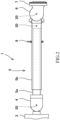
- FIG. 3 is a schematic plan view showing the travel device 11 and the laser scanners 21a and 21b mounted in the vicinity thereof. Each of the laser scanners 21a and 21b is intended for detecting a person.
- the external speaker 24 is installed, for example, on the drive columns 9 or on the bottom surface of the tunnel 5b near the drive columns 9.
- the external speaker 24 is not particularly limited, so long as every person present in a predetermined area in the vicinity of the travel device 11 (e.g., an area that includes the detection areas of the laser scanners 21a and 21b) can hear an announcement from the external speaker 24.
- the installation location of the external speaker 24 and the number of external speakers 24 to be installed may be changed as necessary.
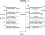
- FIG. 4 is a block diagram schematically showing a connection relationship between the controller and each component of the passenger boarding bridge 1 of FIG. 1 .
- the controller 50 and a communication device 51 of the passenger boarding bridge 1 are, for example, disposed in the cab 6 or the frontmost tunnel 5b.
- the controller 50 may be configured in any manner, so long as the controller 50 has control functions.
- the controller 50 includes, for example, an arithmetic operation unit such as a CPU and a storage unit including a ROM, RAM, etc.
- Control programs for operating the components of the passenger boarding bridge 1 (including an automatic inspection program that will be described below) and information necessary for the operations of the components of the passenger boarding bridge 1 are prestored in the storage unit.
- the arithmetic operation unit CPU
- the arithmetic operation unit can control the operations of the components of the passenger boarding bridge 1.
- the controller 50 may be configured as a single control device performing centralized control, or may be configured as a plurality of control devices performing distributed control in cooperation with each other.
- the communication device 51 is a device that communicates with an external device (one example of the external device is a management server of, for example, a maintenance section that is in charge of the maintenance of the passenger boarding bridge; the management server may be a cloud computing server).
- the communication device 51 may communicate with the external device by wireless and/or wired communication.
- the communication device 51 may be included in the controller 50.
- Examples of devices controlled by the controller 50 include the inclinable floor equipment 61 of the cab 6, the cab rotator 62, the closure 7, the level detector 8, the lifting/lowering device 10, and the travel device 11. It should be noted that, for example, the controller 50 may be divided into individual controllers and an integrated controller. Each of the individual controllers is provided for a corresponding one of the devices, and controls the corresponding device. The integrated controller performs integrated control of, for example, these individual controllers.
- the controller 50 is configured to receive detection signal inputs from the motion sensors 20 and the laser scanners 21, and to cause each of the internal and external speakers 23 and 24 to make a predetermined announcement (i.e., to perform audio output) as necessary.
- the contents of the announcement are prestored in the storage unit as an audio file.
- FIG. 1 shows two internal speakers 23, FIG. 4 shows only one internal speaker 23 as a representative example.
- a system for performing an automatic inspection of a passenger boarding bridge is configured to perform an automatic inspection of the passenger boarding bridge 1 before operating the passenger boarding bridge 1.
- "before operating the passenger boarding bridge 1” means “before docking the passenger boarding bridge 1 with an aircraft", and at the latest, "before the aircraft arrives at the apron EP where the passenger boarding bridge 1 is used”.
- the passenger boarding bridge 1 stands by in a predetermined state at a predetermined standby position.
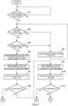
- FIG. 5 and FIG. 6 are flowcharts showing one example of operations that are performed when an automatic inspection is performed before operating the passenger boarding bridge 1. These operations are performed through control by the controller 50.
- An external device transmits an inspection start command to the controller 50.
- the controller 50 Upon receiving (an input of) the inspection start command from the external device via the communication device 51, the controller 50 starts an automatic inspection. Since the aforementioned automatic inspection program is prestored in the storage unit of the controller 50, the controller 50 performs the automatic inspection in accordance with the automatic inspection program. Examples of the external device that transmits the inspection start command include not only the aforementioned management server, but also a mobile terminal such as a smartphone on which dedicated application software is installed.
- Whether the motor is in a normal condition or not is determined based on whether the electric current value of the motor while the motor is thus driven to rotate is within a predetermined range or not.
- there is no abnormality in the motor i.e., in a case where the motor is in a normal condition
- when the motor is driven to rotate in the regular direction for the predetermined time if a predetermined one of the limit switches is not actuated, it is detected that there is abnormality in the predetermined one limit switch or in its circuitry, whereas when the motor is driven to rotate in the reverse direction for the predetermined time, if the other limit switch is not actuated, it is detected that there is abnormality in the other limit switch or in its circuitry.
- the two limit switches are actuated concurrently, it is detected that there is abnormality in the limit switches or in their circuitry.
- the closure (a device) 7 includes, for example, the bellows portion (the body of the device), a motor (a driver) that operates (expands and contracts) the bellows portion, a current sensor that measures an electric current value of the motor, and two limit switches.
- One of the limit switches detects that the operated bellows portion has reached a forward limit position, and the other limit switch detects that the operated bellows portion has reached a backward limit position.
- the motor is driven to rotate in the regular direction for a predetermined time and to rotate in the reverse direction for a predetermined time, and thereby the presence or absence of abnormality in, for example, the motor and the limit switches is detected.
- the level detector (a device) 8 includes, for example, the wheel 8a, a motor (a driver) that operates the wheel 8a (moves the wheel 8a forward and backward), a current sensor that measures an electric current value of the motor, and two limit switches.
- One of the limit switches detects that the operated wheel 8a has reached a forward limit position, and the other limit switch detects that the operated wheel 8a has reached a backward limit position.
- the motor is driven to rotate in the regular direction for a predetermined time and to rotate in the reverse direction for a predetermined time, and thereby the presence or absence of abnormality in, for example, the motor and the limit switches is detected.
- the cab rotator (a device) 62 includes, for example, the entire cab 6 (the body of the device), a motor (a driver) that operates (rotates) the cab 6, a current sensor that measures an electric current value of the motor, an encoder (a rotary encoder) included in the motor, and two limit switches.
- a motor a driver
- a current sensor that measures an electric current value of the motor
- an encoder a rotary encoder included in the motor
- two limit switches When the cab 6 is operated (rotated to the left), one of the limit switches detects that the cab 6 has reached a left rotation limit position, and also, when the cab 6 is operated (rotated to the right), the other limit switch detects that the cab 6 has reached a right rotation limit position.
- the motor is driven to rotate in the regular direction for a predetermined time and to rotate in the reverse direction for a predetermined time, and thereby the presence or absence of abnormality in, for example, the motor and the limit switches is detected.
- whether or not the encoder is in a normal condition is determined (i.e., the presence or absence of abnormality in the encoder is detected) based on whether or not an output value of the encoder is within a normal range in relation to the drive time of the motor.
- the lifting/lowering device (a device) 10 includes, for example, two support pillars (the body of the device) configured to be extendable and retractable, a motor (a driver) that operates, i.e., extends and retracts, the support pillars, a current sensor that measures an electric current value of the motor, an encoder (a rotary encoder) included in the motor, and two limit switches.
- one of the limit switches detects that the lifting/lowering device 10 has reached an extension limit position, and also, when the lifting/lowering device 10 is operated (retracted), the other limit switch detects that the lifting/lowering device 10 has reached a retraction limit position.
- the motor is driven to rotate in the regular direction for a predetermined time and to rotate in the reverse direction for a predetermined time, and thereby the presence or absence of abnormality in, for example, the motor and the limit switches is detected, and in addition, the presence or absence of abnormality in the encoder is detected.
- the travel device (a device) 11 includes, for example, the two travel wheels (the body of the device) 12, two motors (drivers) 13 that rotate the respective travel wheels 12 (in regular and reverse directions); current sensors that measure electric current values of the respective motors 13; and encoders (rotary encoders) included in the respective motors 13.
- the tunnel unit 5 includes, for example, limit switches.
- one of the limit switches detects that the travel device 11 has reached a forward travel limit position (i.e., the tunnel unit 5 has reached an extension limit position), and also, when the travel device 11 travels backward (i.e., when the tunnel unit 5 is retracted), the other limit switch detects that the travel device 11 has reached a backward travel limit position (i.e., the tunnel unit 5 has reached a retraction limit position).
- the two motors are driven to rotate in the regular direction for a predetermined time to cause the travel device 11 to travel forward, and also, the two motors are driven to rotate in the reverse direction for a predetermined time to cause the travel device 11 to travel backward.
- the presence or absence of abnormality in, for example, the motors, the encoders, and the limit switches is detected.
- each device subjected to the operation test includes, for example, a device body, a driver or drivers (a motor or motors) controlled by the controller 50 to operate the device body, and sensors (limit switches, each of which detects the operation state of the device body; an encoder or encoders that detect the operation state of the motor or motors).
- a driver or drivers a motor or motors
- sensors limit switches, each of which detects the operation state of the device body; an encoder or encoders that detect the operation state of the motor or motors.
- each device is caused to operate in one direction, and is then caused to operate in the reverse direction, such that at the end of the operation test, the device is brought back to its original state (i.e., the state that the device is in at the start of the operation test).
- step S1 when an inspection start command is inputted to the controller 50 (YES in step S1), the controller 50 determines whether or not a person has been detected outside the PBB (Passenger Boarding Bridge) based on the presence or absence of a detection signal input from the laser scanners 21a and 21b (step S2). If it is determined that a person has been detected outside the PBB (i.e., if the controller 50 has received a detection signal input from at least one of the laser scanners 21a and 21b), the controller 50 causes the speakers 23 and 24 to make an announcement (i.e., to perform an audio output) that urges the person to retreat (step S4). In this case (i.e., if YES in step S2), the controller 50 may cause only the external speaker 24 to make the announcement.
- PBB Passenger Boarding Bridge
- the controller 50 determines whether or not a person has been detected inside the PBB based on the presence or absence of a detection signal input from the motion sensors 20 (step S3). If it is determined that a person has been detected inside the PBB (i.e., if the controller 50 has received a detection signal input from at least one of the motion sensors 20), the controller 50 causes the speakers 23 and 24 to make an announcement that urges the person to retreat (step S4). In this case (i.e., YES in step S3), the controller 50 may cause only the internal speakers 23 to make the announcement.
- step S5 the controller 50 causes the speakers 23 and 24 to make an announcement notifying that an automatic inspection of the PBB is going to start.
- the controller 50 causes the speakers 23 and 24 to make an announcement notifying that an operation test of the floor of the cab 6 (the inclinable floor equipment 61) is to be performed (step S6). Then, the controller 50 performs the operation test of the floor of the cab 6 (the inclinable floor equipment 61) (step S7).
- step S7 In a case where no abnormality has been detected by the operation test performed in step S7 (i.e., if YES in step S8), the controller 50 causes the speakers 23 and 24 to make an announcement notifying that an operation test of the closure 7 is to be performed next (step S9). Thereafter, the controller 50 performs the operation test of the closure 7 (step S10).
- step S10 In a case where no abnormality has been detected by the operation test performed in step S10 (i.e., if YES in step S11), the controller 50 causes the speakers 23 and 24 to make an announcement notifying that a rotational operation test of the cab 6 is to be performed next (step S21). Thereafter, the controller 50 performs the rotational operation test of the cab 6 (i.e., an operation test of the cab rotator 62) (step S22).
- step S22 In a case where no abnormality has been detected by the operation test performed in step S22 (i.e., if YES in step S23), the controller 50 causes the speakers 23 and 24 to make an announcement notifying that a lifting/lowering operation test of the PBB is to be performed next (step S24). Thereafter, the controller 50 performs the operation test of the lifting/lowering device 10 (the lifting/lowering operation test of the PBB) (step S25).
- step S25 In a case where no abnormality has been detected by the operation test performed in step S25 (i.e., if YES in step S26), the controller 50 causes the speakers 23 and 24 to make an announcement notifying that a travel operation test of the PBB is to be performed next (step S27). Thereafter, the controller 50 performs the operation test of the travel device 11 (the travel operation test of the PBB) (step S28).
- step S28 In a case where no abnormality has been detected by the operation test performed in step S28 (i.e., if YES in step S29), the controller 50 causes the speakers 23 and 24 to make an announcement notifying that an operation test of the level detector is to be performed next (step S30). Thereafter, the controller 50 performs the operation test of the level detector 8 (step S31).
- step S31 In a case where no abnormality has been detected by the operation test performed in step S31 (i.e., if YES in step S32), the controller 50 causes the speakers 23 and 24 to make an announcement notifying that the automatic inspection of the PBB is going to end (step S34). Then, the controller 50 ends the automatic inspection.
- the controller 50 causes the speakers 23 and 24 to make an announcement notifying that there is abnormality in the PBB. Thereafter, the controller 50 further causes the speakers 23 and 24 to make an announcement notifying that the automatic inspection of the PBB is going to end (step S34), and then ends the automatic inspection.
- the controller 50 stores therein inspection results of the automatic inspection, and transmits the inspection results to the external device via the communication device 51. If the inspection results of the automatic inspection indicate that there is abnormality in the passenger boarding bridge 1, a different passenger boarding bridge in a normal condition is operated instead of the passenger boarding bridge 1.
- step S7, S10, S22, S25, S28, and S31 are merely one example, and the order of the operation tests may be changed, or other operation tests may be performed.
- the floor of the cab 6 does not include the inclinable floor and is entirely configured as a fixed floor, the above-described steps S6 to S8 are eliminated.
- Step S5 the step of making the announcement notifying that the automatic inspection is going to start
- step S1 between steps S1 and S2
- the operation test-related information may contain one of, or both of, the following pieces of information: information indicating that the operation test of the device is to be performed (i.e., is going to start); and information that urges a person or persons to retreat.
- the input of the inspection start command to the controller 50 can be performed via communications, for example, by performing an inspection start operation with an external device that is located at a remote position from the passenger boarding bridge 1. By merely performing the inspection start operation, the automatic inspection can be carried out.
- the controller 50 determines whether or not a person has been detected outside the PBB (Passenger Boarding Bridge) based on the presence or absence of a detection signal input from the laser scanners 21a and 21b, and determines whether or not a person has been detected inside the PBB based on the presence or absence of a detection signal input from the motion sensors 20. If it is determined that a person has been detected outside and/or inside the PBB, the controller 50 causes the speakers 23 and 24 to make an announcement that urges the person to retreat. Thereafter, when no person is detected any more both outside and inside the PBB, the controller 50 performs the operation test. This makes it possible to perform the operation test in improved coordination with persons. Here, when no person is detected any more both outside and inside the PBB, the operation test may be performed (started) automatically, or the operation test may be started upon receiving a specific command.
- PBB Passenger Boarding Bridge
- the controller 50 may always determine whether or not a person has been detected outside the PBB and whether or not a person has been detected inside the PBB. Then, for example, in a case where a person has been detected outside and/or inside the PBB before performing the operation test of each device, the controller 50 may cause the speakers 23 and 24 to make an announcement that urges the person to retreat, and then, when no person is detected any more both outside and inside the PBB, the controller 50 may perform the operation test. This makes it possible to perform the operation test in improved coordination with persons.
- the operation test may be performed (started) automatically, or the operation test may be started upon receiving a specific command.
- the controller 50 may temporarily stop the operation test, cause the speakers 23 and 24 to make an announcement that urges the person to retreat, and thereafter, when no person is detected any more both outside and inside the PBB, resume the operation test. This makes it possible to perform the operation test in improved coordination with persons.
- the controller 50 may resume the operation test automatically, or may resume the operation test upon receiving a specific command.
- the device in the operation test of each device, the device is caused to operate in one direction, and then caused to operate in the reverse direction (i.e., the direction opposite to the one direction), such that at the end of the operation test, the device is brought back to a state that the device is in at the start of the operation test. Therefore, when all the operation tests are ended, the passenger boarding bridge 1 is in a state that the passenger boarding bridge 1 is in before the start of the first operation test.
- the passenger boarding bridge 1 is in a predetermined state (i.e., a state that the passenger boarding bridge 1 is in before the start of the inspection) at a predetermined standby position where the passenger boarding bridge 1 stands by before being operated.
- a predetermined state i.e., a state that the passenger boarding bridge 1 is in before the start of the inspection
- the announcement equipment (the speakers 23 and 24) is used as the notifier that notifies the operation test-related information.
- a display device that displays characters, symbols, etc., a siren such as a whistle siren, a revolving lamp, lighting equipment, or an area alert device utilizing weak radio waves may be used as the notifier.
- the operation test-related information is information that is notified inside and/or outside the passenger boarding bridge 1 by the notifier during a period from when the inspection start command is inputted to the controller 50 until the operation test of the last device is ended (i.e., during an automatic inspection period).
- the operation test-related information includes at least one of the following types of information: information that is notified before the start of the operation test of the first device among the devices, the information indicating that the automatic inspection is going to start (see step S5, for example); information that is notified during the automatic inspection period, the information indicating that the automatic inspection is being performed; information that is notified before the operation test of each device is performed (started), the information indicating that the operation test of the device is going to start; information that is notified while the operation test of each device is being performed, the information indicating that the operation test of the device is being performed; and information that urges a person to retreat.
- the operation test-related information may be notified in any manner, so long as the notified information is recognizable by a person, such as a worker.
- the operation test-related information may be notified, for example, in the form of verbal information outputted from a speaker, or in the form of audio information outputted from a speaker, such as particular music or a sound of a siren or the like, or in the form of light information from, for example, a revolving lamp, or any other lighting equipment, that emits light in a particular color, or in the form of characters and/or symbols displayed by a display device.
- the operation test-related information is notified during the automatic inspection period, and the operation test-related information may be notified not only before the start of the operation test of each device, but also during the operation test of each device or through the entire automatic inspection period, for example, in the form of audio information such as music or a sound of a siren or the like, or in the form of light information from, for example, a revolving lamp, or other lighting equipment, that emits light in a particular color.
- the present invention is useful, for example, as a system for performing an automatic inspection of a passenger boarding bridge, the system making it possible to perform the automatic inspection of the passenger boarding bridge in improved coordination with persons, such as workers.
Landscapes
- Engineering & Computer Science (AREA)
- Business, Economics & Management (AREA)
- Human Resources & Organizations (AREA)
- General Physics & Mathematics (AREA)
- Physics & Mathematics (AREA)
- Strategic Management (AREA)
- Economics (AREA)
- Marketing (AREA)
- Tourism & Hospitality (AREA)
- Entrepreneurship & Innovation (AREA)
- General Business, Economics & Management (AREA)
- Theoretical Computer Science (AREA)
- Aviation & Aerospace Engineering (AREA)
- Mechanical Engineering (AREA)
- Architecture (AREA)
- Structural Engineering (AREA)
- Civil Engineering (AREA)
- Quality & Reliability (AREA)
- Operations Research (AREA)
- Emergency Management (AREA)
- Game Theory and Decision Science (AREA)
- Educational Administration (AREA)
- Development Economics (AREA)
- Health & Medical Sciences (AREA)
- General Health & Medical Sciences (AREA)
- Primary Health Care (AREA)
- Bridges Or Land Bridges (AREA)
- Management, Administration, Business Operations System, And Electronic Commerce (AREA)
Claims (4)
- System zur Durchführung einer automatischen Inspektion einer Fluggastbrücke (1), das eine Vielzahl von Vorrichtungen beinhaltet, die bedienbar sind,
wobei das System die Fluggastbrücke (1) umfasst, die beinhaltet:eine Rotunde (4) zur Verbindung mit einem Abfertigungsgebäude (2), und die um eine vertikale Achse drehbar ist;eine Tunneleinheit (5), deren proximales Ende mit der Rotunde (4) verbunden ist, sodass die Tunneleinheit (5) anhebbar und absenkbar ist, wobei die Tunneleinheit (5) eine Vielzahl von Tunneln (5a, 5b) beinhaltet, die teleskopisch zusammengefügt sind, wobei die Tunneleinheit (5) konfiguriert ist, um in einer Längsrichtung ausfahrbar und einziehbar zu sein;eine Kabine (6), die drehbar an einem distalen Ende der Tunneleinheit (5) bereitgestellt ist; undeine Antriebssäule (9), die an einem vordersten der Tunnel (5b) der Tunneleinheit (5) oder an der Kabine (6) montiert ist, wobei die Antriebssäule (9) eine Hebe-/Senkvorrichtung (10) und eine Verfahrvorrichtung (11) beinhaltet, wobei die Hebe-/Senkvorrichtung (10) konfiguriert ist, um die Tunneleinheit (5) und die Kabine (6) anzuheben und abzusenken, wobei die Verfahrvorrichtung (11) unter der Hebe-/Senkvorrichtung (10) montiert ist und konfiguriert ist, um auf einem Boden zu verfahren, wobeijede der Hebe-/Senkvorrichtung (10) und der Verfahrvorrichtung (11) eine der Vielzahl von Vorrichtungen ist,wobei das System weiter umfasst:einen Melder (23, 24), der an mindestens einer von der Decke der Rotunde (4), der Decke der Kabine (6), der Antriebssäule (9) und der Bodenoberfläche des Tunnels (5b) in der Nähe der Antriebssäule (9) bereitgestellt ist;eine Steuereinheit (50), die konfiguriert ist, um jede der Vorrichtungen und den Melder (23, 24) zu steuern; undeine Kommunikationsvorrichtung (51), die konfiguriert ist, um mit einer externen Vorrichtung zu kommunizieren, wobei sich die externe Vorrichtung an einer von der Fluggastbrücke (1) entfernten Position befindet, wobei die externe Vorrichtung konfiguriert ist, um einen Inspektionsstartbefehl an die Steuereinheit (50) zu übertragen, wobeidie Steuereinheit (50) konfiguriert ist, um:
wenn der Inspektionsstartbefehl in die Steuereinheit (50) eingegeben wird, einen Betriebstest an jeder der Vorrichtungen in einer vorbestimmten Reihenfolge durchzuführen, um das Vorhandensein oder Nichtvorhandensein einer Anomalie in jeder Vorrichtung zu erkennen;dadurch gekennzeichnet, dass die Steuereinheit (50) konfiguriert ist, um:
während eines Zeitraums von der Eingabe des Inspektionsstartbefehls in die Steuereinheit (50) bis zum Abschluss des Betriebstests einer letzten Vorrichtung unter den Vorrichtungen, den Melder (23, 24) zu veranlassen, betriebstestbezogene Informationen innerhalb und/oder außerhalb der Fluggastbrücke (1) zu melden, undwobei die betriebstestbezogenen Informationen mindestens eine der folgenden Informationstypen beinhalten:Informationen, die vor Beginn des Betriebstests einer ersten Vorrichtung unter den Vorrichtungen gemeldet werden, wobei die Informationen angeben, dass die automatische Inspektion beginnen wird;Informationen, die während eines automatischen Inspektionszeitraums gemeldet werden, wobei die Informationen angeben, dass die automatische Inspektion durchgeführt wird;Informationen, die vor der Durchführung des Betriebstests jeder Vorrichtung gemeldet werden, wobei die Informationen angeben, dass der Betriebstest der Vorrichtung beginnt;Informationen, die während der Durchführung des Betriebstests jeder Vorrichtung gemeldet werden, wobei die Informationen angeben, dass der Betriebstest der Vorrichtung durchgeführt wird; undInformationen, die eine Person auffordern, zurückzuweichen. - System zur Durchführung einer automatischen Inspektion einer Fluggastbrücke (1) nach Anspruch 1, wobei das System weiter umfasst:einen ersten Sensor (20), der eine Person innerhalb der Fluggastbrücke (1) erkennt; undeinen zweiten Sensor (21), der eine Person außerhalb der Fluggastbrücke (1) erkennt, wobeidie Steuereinheit (50) konfiguriert ist, um:in einem Fall, in dem eine Person vom ersten Sensor (20) und/oder vom zweiten Sensor (21) erkannt wird, bevor der Betriebstest jeder Vorrichtung durchgeführt wird, den Melder (23, 24) zu veranlassen, die betriebstestbezogenen Informationen zu melden, welche die Person auffordern, zurückzuweichen; und danachden Betriebstest durchzuführen, wenn jeder von dem ersten Sensor (20) und dem zweiten Sensor (21) keine Person mehr erkennt.
- System zur Durchführung einer automatischen Inspektion einer Fluggastbrücke (1) nach Anspruch 1, wobei das System weiter umfasst:einen ersten Sensor (20), der eine Person innerhalb der Fluggastbrücke erkennt; undeinen zweiten Sensor (21), der eine Person außerhalb der Fluggastbrücke erkennt, wobeidie Steuereinheit (50) konfiguriert ist, um:in einem Fall, in dem eine Person vom ersten Sensor (20) und/oder vom zweiten Sensor (21) erkannt wird, während der Betriebstest jeder Vorrichtung durchgeführt wird, den Betriebstest vorübergehend anzuhalten, und den Melder (23, 24) zu veranlassen, die betriebstestbezogenen Informationen zu melden, welche die Person auffordern, zurückzuweichen; und danachden Betriebstest wieder aufzunehmen, wenn jeder von dem ersten Sensor (20) und dem zweiten Sensor (21) keine Person mehr erkennt.
- System zur Durchführung einer automatischen Inspektion einer Fluggastbrücke nach (1) einem der Ansprüche 1 bis 3, wobei
beim Durchführen des Betriebstests an jeder Vorrichtung die Steuereinheit (50) konfiguriert ist, um die Steuerung der Vorrichtung durchzuführen, um:die Vorrichtung zu veranlassen, in eine Richtung zu arbeiten; und danachdie Vorrichtung zu veranlassen, in eine entgegengesetzte Richtung zu arbeiten, sodass die Vorrichtung am Ende des Betriebstests in den Zustand zurückversetzt wird, in dem sich die Vorrichtung zu Beginn des Betriebstests befand.
Applications Claiming Priority (1)
| Application Number | Priority Date | Filing Date | Title |
|---|---|---|---|
| PCT/JP2019/037287 WO2021059330A1 (ja) | 2019-09-24 | 2019-09-24 | 旅客搭乗橋の自動点検システム |
Publications (3)
| Publication Number | Publication Date |
|---|---|
| EP4036016A1 EP4036016A1 (de) | 2022-08-03 |
| EP4036016A4 EP4036016A4 (de) | 2023-06-14 |
| EP4036016B1 true EP4036016B1 (de) | 2025-03-19 |
Family
ID=75165186
Family Applications (1)
| Application Number | Title | Priority Date | Filing Date |
|---|---|---|---|
| EP19946263.1A Active EP4036016B1 (de) | 2019-09-24 | 2019-09-24 | System zur durchführung einer automatischen inspektion einer fluggastbrücke |
Country Status (4)
| Country | Link |
|---|---|
| US (1) | US12269613B2 (de) |
| EP (1) | EP4036016B1 (de) |
| JP (2) | JP6893589B1 (de) |
| WO (1) | WO2021059330A1 (de) |
Families Citing this family (2)
| Publication number | Priority date | Publication date | Assignee | Title |
|---|---|---|---|---|
| CN118190392B (zh) * | 2024-05-17 | 2024-09-03 | 四川省机场集团有限公司成都天府国际机场分公司 | 一种登机桥接机检测系统及方法 |
| CN119066313A (zh) * | 2024-08-23 | 2024-12-03 | 内蒙古自治区民航机场集团有限责任公司 | 一种无人驾驶登机桥集中管控的运行调度方法 |
Family Cites Families (10)
| Publication number | Priority date | Publication date | Assignee | Title |
|---|---|---|---|---|
| JP3255696B2 (ja) * | 1992-04-10 | 2002-02-12 | 松下電器産業株式会社 | 設備器具の制御装置 |
| JPH1151453A (ja) * | 1997-07-31 | 1999-02-26 | Sanyo Electric Co Ltd | 空気調和装置 |
| JP4066419B2 (ja) * | 2002-11-15 | 2008-03-26 | 新明和工業株式会社 | ボーディングブリッジの集中遠隔監視システム |
| JP4559712B2 (ja) * | 2003-06-11 | 2010-10-13 | 東芝モバイルディスプレイ株式会社 | アレイ基板およびアレイ基板の検査方法 |
| CN2635520Y (zh) * | 2003-08-29 | 2004-08-25 | 中国国际海运集装箱(集团)股份有限公司 | 安全检测型旅客登机桥 |
| JP4522690B2 (ja) * | 2003-10-28 | 2010-08-11 | 三菱電機株式会社 | 空気調和装置 |
| JP2013242642A (ja) * | 2012-05-18 | 2013-12-05 | Toshiba Corp | 監視システムおよび監視方法 |
| JP6054172B2 (ja) * | 2012-12-26 | 2016-12-27 | 株式会社東芝 | 改札機および改札機の集札処理方法 |
| JP2019526477A (ja) | 2016-08-15 | 2019-09-19 | シンガポール テクノロジーズ ダイナミックス ピーティーイー リミテッド | 自動乗客搭乗橋ドッキングシステム |
| JP6242961B2 (ja) * | 2016-08-15 | 2017-12-06 | 株式会社東芝 | 改札機 |
-
2019
- 2019-09-24 WO PCT/JP2019/037287 patent/WO2021059330A1/ja not_active Ceased
- 2019-09-24 EP EP19946263.1A patent/EP4036016B1/de active Active
- 2019-09-24 JP JP2021502628A patent/JP6893589B1/ja active Active
- 2019-09-24 US US17/634,203 patent/US12269613B2/en active Active
-
2021
- 2021-06-01 JP JP2021092389A patent/JP7205978B2/ja active Active
Also Published As
| Publication number | Publication date |
|---|---|
| JP2021121544A (ja) | 2021-08-26 |
| JPWO2021059330A1 (ja) | 2021-10-14 |
| JP7205978B2 (ja) | 2023-01-17 |
| WO2021059330A1 (ja) | 2021-04-01 |
| EP4036016A4 (de) | 2023-06-14 |
| JP6893589B1 (ja) | 2021-06-23 |
| US12269613B2 (en) | 2025-04-08 |
| EP4036016A1 (de) | 2022-08-03 |
| US20220315245A1 (en) | 2022-10-06 |
Similar Documents
| Publication | Publication Date | Title |
|---|---|---|
| EP3653515A1 (de) | Fluggastbrücke | |
| US10934138B2 (en) | Crawler crane | |
| EP4036016B1 (de) | System zur durchführung einer automatischen inspektion einer fluggastbrücke | |
| CN105544985A (zh) | 一种用于建筑工地的升降式施工平台车 | |
| EP4053022B1 (de) | Fluggastbrücke | |
| WO2018096773A1 (ja) | 旅客搭乗橋 | |
| US20250313347A1 (en) | Airport ground support equipment | |
| US12404037B2 (en) | Passenger boarding bridge | |
| JP6845976B1 (ja) | 旅客搭乗橋 | |
| JP7457873B2 (ja) | 旅客搭乗橋 | |
| JP4051222B2 (ja) | ボーディングブリッジの制御装置及びこれを備えるボーディングブリッジ | |
| EP4501798A1 (de) | Bodenhilfsgerät für flughäfen | |
| WO2022190667A1 (ja) | 旅客搭乗橋 | |
| JP7723628B2 (ja) | 旅客搭乗橋 | |
| EP4691920A1 (de) | Fluggastbrücke | |
| US12304656B2 (en) | Passenger boarding bridge monitoring device | |
| JP6694330B2 (ja) | 旅客搭乗橋 | |
| JP6338908B2 (ja) | 旅客搭乗橋 | |
| JP7213212B2 (ja) | 旅客搭乗橋 |
Legal Events
| Date | Code | Title | Description |
|---|---|---|---|
| STAA | Information on the status of an ep patent application or granted ep patent |
Free format text: STATUS: THE INTERNATIONAL PUBLICATION HAS BEEN MADE |
|
| PUAI | Public reference made under article 153(3) epc to a published international application that has entered the european phase |
Free format text: ORIGINAL CODE: 0009012 |
|
| STAA | Information on the status of an ep patent application or granted ep patent |
Free format text: STATUS: REQUEST FOR EXAMINATION WAS MADE |
|
| 17P | Request for examination filed |
Effective date: 20220304 |
|
| AK | Designated contracting states |
Kind code of ref document: A1 Designated state(s): AL AT BE BG CH CY CZ DE DK EE ES FI FR GB GR HR HU IE IS IT LI LT LU LV MC MK MT NL NO PL PT RO RS SE SI SK SM TR |
|
| DAV | Request for validation of the european patent (deleted) | ||
| DAX | Request for extension of the european patent (deleted) | ||
| A4 | Supplementary search report drawn up and despatched |
Effective date: 20230512 |
|
| RIC1 | Information provided on ipc code assigned before grant |
Ipc: G06Q 10/063 20230101ALI20230508BHEP Ipc: G06Q 10/20 20230101ALI20230508BHEP Ipc: G06Q 50/30 20120101ALI20230508BHEP Ipc: B64F 1/36 20170101ALI20230508BHEP Ipc: B64F 1/305 20060101AFI20230508BHEP |
|
| GRAP | Despatch of communication of intention to grant a patent |
Free format text: ORIGINAL CODE: EPIDOSNIGR1 |
|
| STAA | Information on the status of an ep patent application or granted ep patent |
Free format text: STATUS: GRANT OF PATENT IS INTENDED |
|
| RIC1 | Information provided on ipc code assigned before grant |
Ipc: G06Q 50/40 20240101ALI20240730BHEP Ipc: G06Q 10/063 20230101ALI20240730BHEP Ipc: G06Q 10/20 20230101ALI20240730BHEP Ipc: B64F 1/36 20170101ALI20240730BHEP Ipc: B64F 1/305 20060101AFI20240730BHEP |
|
| INTG | Intention to grant announced |
Effective date: 20240819 |
|
| GRAJ | Information related to disapproval of communication of intention to grant by the applicant or resumption of examination proceedings by the epo deleted |
Free format text: ORIGINAL CODE: EPIDOSDIGR1 |
|
| STAA | Information on the status of an ep patent application or granted ep patent |
Free format text: STATUS: REQUEST FOR EXAMINATION WAS MADE |
|
| GRAP | Despatch of communication of intention to grant a patent |
Free format text: ORIGINAL CODE: EPIDOSNIGR1 |
|
| STAA | Information on the status of an ep patent application or granted ep patent |
Free format text: STATUS: GRANT OF PATENT IS INTENDED |
|
| INTC | Intention to grant announced (deleted) | ||
| INTG | Intention to grant announced |
Effective date: 20241119 |
|
| GRAS | Grant fee paid |
Free format text: ORIGINAL CODE: EPIDOSNIGR3 |
|
| GRAA | (expected) grant |
Free format text: ORIGINAL CODE: 0009210 |
|
| STAA | Information on the status of an ep patent application or granted ep patent |
Free format text: STATUS: THE PATENT HAS BEEN GRANTED |
|
| AK | Designated contracting states |
Kind code of ref document: B1 Designated state(s): AL AT BE BG CH CY CZ DE DK EE ES FI FR GB GR HR HU IE IS IT LI LT LU LV MC MK MT NL NO PL PT RO RS SE SI SK SM TR |
|
| P01 | Opt-out of the competence of the unified patent court (upc) registered |
Free format text: CASE NUMBER: APP_6797/2025 Effective date: 20250210 |
|
| REG | Reference to a national code |
Ref country code: GB Ref legal event code: FG4D |
|
| REG | Reference to a national code |
Ref country code: CH Ref legal event code: EP |
|
| REG | Reference to a national code |
Ref country code: DE Ref legal event code: R096 Ref document number: 602019067649 Country of ref document: DE |
|
| REG | Reference to a national code |
Ref country code: IE Ref legal event code: FG4D |
|
| PG25 | Lapsed in a contracting state [announced via postgrant information from national office to epo] |
Ref country code: RS Free format text: LAPSE BECAUSE OF FAILURE TO SUBMIT A TRANSLATION OF THE DESCRIPTION OR TO PAY THE FEE WITHIN THE PRESCRIBED TIME-LIMIT Effective date: 20250619 |
|
| PG25 | Lapsed in a contracting state [announced via postgrant information from national office to epo] |
Ref country code: FI Free format text: LAPSE BECAUSE OF FAILURE TO SUBMIT A TRANSLATION OF THE DESCRIPTION OR TO PAY THE FEE WITHIN THE PRESCRIBED TIME-LIMIT Effective date: 20250319 |
|
| REG | Reference to a national code |
Ref country code: LT Ref legal event code: MG9D |
|
| PG25 | Lapsed in a contracting state [announced via postgrant information from national office to epo] |
Ref country code: NO Free format text: LAPSE BECAUSE OF FAILURE TO SUBMIT A TRANSLATION OF THE DESCRIPTION OR TO PAY THE FEE WITHIN THE PRESCRIBED TIME-LIMIT Effective date: 20250619 |
|
| PG25 | Lapsed in a contracting state [announced via postgrant information from national office to epo] |
Ref country code: HR Free format text: LAPSE BECAUSE OF FAILURE TO SUBMIT A TRANSLATION OF THE DESCRIPTION OR TO PAY THE FEE WITHIN THE PRESCRIBED TIME-LIMIT Effective date: 20250319 |
|
| PG25 | Lapsed in a contracting state [announced via postgrant information from national office to epo] |
Ref country code: LV Free format text: LAPSE BECAUSE OF FAILURE TO SUBMIT A TRANSLATION OF THE DESCRIPTION OR TO PAY THE FEE WITHIN THE PRESCRIBED TIME-LIMIT Effective date: 20250319 |
|
| PG25 | Lapsed in a contracting state [announced via postgrant information from national office to epo] |
Ref country code: BG Free format text: LAPSE BECAUSE OF FAILURE TO SUBMIT A TRANSLATION OF THE DESCRIPTION OR TO PAY THE FEE WITHIN THE PRESCRIBED TIME-LIMIT Effective date: 20250319 Ref country code: GR Free format text: LAPSE BECAUSE OF FAILURE TO SUBMIT A TRANSLATION OF THE DESCRIPTION OR TO PAY THE FEE WITHIN THE PRESCRIBED TIME-LIMIT Effective date: 20250620 |
|
| REG | Reference to a national code |
Ref country code: NL Ref legal event code: MP Effective date: 20250319 |
|
| REG | Reference to a national code |
Ref country code: AT Ref legal event code: MK05 Ref document number: 1776791 Country of ref document: AT Kind code of ref document: T Effective date: 20250319 |
|
| PG25 | Lapsed in a contracting state [announced via postgrant information from national office to epo] |
Ref country code: NL Free format text: LAPSE BECAUSE OF FAILURE TO SUBMIT A TRANSLATION OF THE DESCRIPTION OR TO PAY THE FEE WITHIN THE PRESCRIBED TIME-LIMIT Effective date: 20250319 |
|
| PG25 | Lapsed in a contracting state [announced via postgrant information from national office to epo] |
Ref country code: SE Free format text: LAPSE BECAUSE OF FAILURE TO SUBMIT A TRANSLATION OF THE DESCRIPTION OR TO PAY THE FEE WITHIN THE PRESCRIBED TIME-LIMIT Effective date: 20250319 |
|
| PG25 | Lapsed in a contracting state [announced via postgrant information from national office to epo] |
Ref country code: SM Free format text: LAPSE BECAUSE OF FAILURE TO SUBMIT A TRANSLATION OF THE DESCRIPTION OR TO PAY THE FEE WITHIN THE PRESCRIBED TIME-LIMIT Effective date: 20250319 |
|
| PG25 | Lapsed in a contracting state [announced via postgrant information from national office to epo] |
Ref country code: ES Free format text: LAPSE BECAUSE OF FAILURE TO SUBMIT A TRANSLATION OF THE DESCRIPTION OR TO PAY THE FEE WITHIN THE PRESCRIBED TIME-LIMIT Effective date: 20250319 Ref country code: PT Free format text: LAPSE BECAUSE OF FAILURE TO SUBMIT A TRANSLATION OF THE DESCRIPTION OR TO PAY THE FEE WITHIN THE PRESCRIBED TIME-LIMIT Effective date: 20250721 |
|
| PGFP | Annual fee paid to national office [announced via postgrant information from national office to epo] |
Ref country code: DE Payment date: 20250917 Year of fee payment: 7 |
|
| PG25 | Lapsed in a contracting state [announced via postgrant information from national office to epo] |
Ref country code: IT Free format text: LAPSE BECAUSE OF FAILURE TO SUBMIT A TRANSLATION OF THE DESCRIPTION OR TO PAY THE FEE WITHIN THE PRESCRIBED TIME-LIMIT Effective date: 20250319 Ref country code: PL Free format text: LAPSE BECAUSE OF FAILURE TO SUBMIT A TRANSLATION OF THE DESCRIPTION OR TO PAY THE FEE WITHIN THE PRESCRIBED TIME-LIMIT Effective date: 20250319 |
|
| PGFP | Annual fee paid to national office [announced via postgrant information from national office to epo] |
Ref country code: GB Payment date: 20250916 Year of fee payment: 7 |
|
| PG25 | Lapsed in a contracting state [announced via postgrant information from national office to epo] |
Ref country code: AT Free format text: LAPSE BECAUSE OF FAILURE TO SUBMIT A TRANSLATION OF THE DESCRIPTION OR TO PAY THE FEE WITHIN THE PRESCRIBED TIME-LIMIT Effective date: 20250319 |
|
| PGFP | Annual fee paid to national office [announced via postgrant information from national office to epo] |
Ref country code: FR Payment date: 20250917 Year of fee payment: 7 |
|
| PG25 | Lapsed in a contracting state [announced via postgrant information from national office to epo] |
Ref country code: CZ Free format text: LAPSE BECAUSE OF FAILURE TO SUBMIT A TRANSLATION OF THE DESCRIPTION OR TO PAY THE FEE WITHIN THE PRESCRIBED TIME-LIMIT Effective date: 20250319 Ref country code: EE Free format text: LAPSE BECAUSE OF FAILURE TO SUBMIT A TRANSLATION OF THE DESCRIPTION OR TO PAY THE FEE WITHIN THE PRESCRIBED TIME-LIMIT Effective date: 20250319 |
|
| PG25 | Lapsed in a contracting state [announced via postgrant information from national office to epo] |
Ref country code: RO Free format text: LAPSE BECAUSE OF FAILURE TO SUBMIT A TRANSLATION OF THE DESCRIPTION OR TO PAY THE FEE WITHIN THE PRESCRIBED TIME-LIMIT Effective date: 20250319 |
|
| PG25 | Lapsed in a contracting state [announced via postgrant information from national office to epo] |
Ref country code: SK Free format text: LAPSE BECAUSE OF FAILURE TO SUBMIT A TRANSLATION OF THE DESCRIPTION OR TO PAY THE FEE WITHIN THE PRESCRIBED TIME-LIMIT Effective date: 20250319 |
|
| PG25 | Lapsed in a contracting state [announced via postgrant information from national office to epo] |
Ref country code: IS Free format text: LAPSE BECAUSE OF FAILURE TO SUBMIT A TRANSLATION OF THE DESCRIPTION OR TO PAY THE FEE WITHIN THE PRESCRIBED TIME-LIMIT Effective date: 20250719 |
|
| REG | Reference to a national code |
Ref country code: DE Ref legal event code: R097 Ref document number: 602019067649 Country of ref document: DE |
|
| PG25 | Lapsed in a contracting state [announced via postgrant information from national office to epo] |
Ref country code: DK Free format text: LAPSE BECAUSE OF FAILURE TO SUBMIT A TRANSLATION OF THE DESCRIPTION OR TO PAY THE FEE WITHIN THE PRESCRIBED TIME-LIMIT Effective date: 20250319 |
|
| PLBE | No opposition filed within time limit |
Free format text: ORIGINAL CODE: 0009261 |
|
| STAA | Information on the status of an ep patent application or granted ep patent |
Free format text: STATUS: NO OPPOSITION FILED WITHIN TIME LIMIT |
|
| REG | Reference to a national code |
Ref country code: CH Ref legal event code: L10 Free format text: ST27 STATUS EVENT CODE: U-0-0-L10-L00 (AS PROVIDED BY THE NATIONAL OFFICE) Effective date: 20260128 |
|
| 26N | No opposition filed |
Effective date: 20251222 |