EP4035918B1 - Wärmetauscher mit dichtleiste - Google Patents
Wärmetauscher mit dichtleiste Download PDFInfo
- Publication number
- EP4035918B1 EP4035918B1 EP22151436.7A EP22151436A EP4035918B1 EP 4035918 B1 EP4035918 B1 EP 4035918B1 EP 22151436 A EP22151436 A EP 22151436A EP 4035918 B1 EP4035918 B1 EP 4035918B1
- Authority
- EP
- European Patent Office
- Prior art keywords
- heat exchanger
- sealing strip
- delimiting element
- sealing
- boxes
- Prior art date
- Legal status (The legal status is an assumption and is not a legal conclusion. Google has not performed a legal analysis and makes no representation as to the accuracy of the status listed.)
- Active
Links
Images


Classifications
-
- F—MECHANICAL ENGINEERING; LIGHTING; HEATING; WEAPONS; BLASTING
- F28—HEAT EXCHANGE IN GENERAL
- F28D—HEAT-EXCHANGE APPARATUS, NOT PROVIDED FOR IN ANOTHER SUBCLASS, IN WHICH THE HEAT-EXCHANGE MEDIA DO NOT COME INTO DIRECT CONTACT
- F28D1/00—Heat-exchange apparatus having stationary conduit assemblies for one heat-exchange medium only, the media being in contact with different sides of the conduit wall, in which the other heat-exchange medium is a large body of fluid, e.g. domestic or motor car radiators
- F28D1/02—Heat-exchange apparatus having stationary conduit assemblies for one heat-exchange medium only, the media being in contact with different sides of the conduit wall, in which the other heat-exchange medium is a large body of fluid, e.g. domestic or motor car radiators with heat-exchange conduits immersed in the body of fluid
- F28D1/04—Heat-exchange apparatus having stationary conduit assemblies for one heat-exchange medium only, the media being in contact with different sides of the conduit wall, in which the other heat-exchange medium is a large body of fluid, e.g. domestic or motor car radiators with heat-exchange conduits immersed in the body of fluid with tubular conduits
- F28D1/053—Heat-exchange apparatus having stationary conduit assemblies for one heat-exchange medium only, the media being in contact with different sides of the conduit wall, in which the other heat-exchange medium is a large body of fluid, e.g. domestic or motor car radiators with heat-exchange conduits immersed in the body of fluid with tubular conduits the conduits being straight
- F28D1/05316—Assemblies of conduits connected to common headers, e.g. core type radiators
-
- B—PERFORMING OPERATIONS; TRANSPORTING
- B60—VEHICLES IN GENERAL
- B60K—ARRANGEMENT OR MOUNTING OF PROPULSION UNITS OR OF TRANSMISSIONS IN VEHICLES; ARRANGEMENT OR MOUNTING OF PLURAL DIVERSE PRIME-MOVERS IN VEHICLES; AUXILIARY DRIVES FOR VEHICLES; INSTRUMENTATION OR DASHBOARDS FOR VEHICLES; ARRANGEMENTS IN CONNECTION WITH COOLING, AIR INTAKE, GAS EXHAUST OR FUEL SUPPLY OF PROPULSION UNITS IN VEHICLES
- B60K11/00—Arrangement in connection with cooling of propulsion units
- B60K11/02—Arrangement in connection with cooling of propulsion units with liquid cooling
- B60K11/04—Arrangement or mounting of radiators, radiator shutters, or radiator blinds
-
- F—MECHANICAL ENGINEERING; LIGHTING; HEATING; WEAPONS; BLASTING
- F28—HEAT EXCHANGE IN GENERAL
- F28D—HEAT-EXCHANGE APPARATUS, NOT PROVIDED FOR IN ANOTHER SUBCLASS, IN WHICH THE HEAT-EXCHANGE MEDIA DO NOT COME INTO DIRECT CONTACT
- F28D1/00—Heat-exchange apparatus having stationary conduit assemblies for one heat-exchange medium only, the media being in contact with different sides of the conduit wall, in which the other heat-exchange medium is a large body of fluid, e.g. domestic or motor car radiators
- F28D1/02—Heat-exchange apparatus having stationary conduit assemblies for one heat-exchange medium only, the media being in contact with different sides of the conduit wall, in which the other heat-exchange medium is a large body of fluid, e.g. domestic or motor car radiators with heat-exchange conduits immersed in the body of fluid
- F28D1/04—Heat-exchange apparatus having stationary conduit assemblies for one heat-exchange medium only, the media being in contact with different sides of the conduit wall, in which the other heat-exchange medium is a large body of fluid, e.g. domestic or motor car radiators with heat-exchange conduits immersed in the body of fluid with tubular conduits
- F28D1/053—Heat-exchange apparatus having stationary conduit assemblies for one heat-exchange medium only, the media being in contact with different sides of the conduit wall, in which the other heat-exchange medium is a large body of fluid, e.g. domestic or motor car radiators with heat-exchange conduits immersed in the body of fluid with tubular conduits the conduits being straight
- F28D1/0535—Heat-exchange apparatus having stationary conduit assemblies for one heat-exchange medium only, the media being in contact with different sides of the conduit wall, in which the other heat-exchange medium is a large body of fluid, e.g. domestic or motor car radiators with heat-exchange conduits immersed in the body of fluid with tubular conduits the conduits being straight the conduits having a non-circular cross-section
- F28D1/05366—Assemblies of conduits connected to common headers, e.g. core type radiators
-
- F—MECHANICAL ENGINEERING; LIGHTING; HEATING; WEAPONS; BLASTING
- F28—HEAT EXCHANGE IN GENERAL
- F28F—DETAILS OF HEAT-EXCHANGE AND HEAT-TRANSFER APPARATUS, OF GENERAL APPLICATION
- F28F9/00—Casings; Header boxes; Auxiliary supports for elements; Auxiliary members within casings
- F28F9/005—Other auxiliary members within casings, e.g. internal filling means or sealing means
-
- F—MECHANICAL ENGINEERING; LIGHTING; HEATING; WEAPONS; BLASTING
- F28—HEAT EXCHANGE IN GENERAL
- F28F—DETAILS OF HEAT-EXCHANGE AND HEAT-TRANSFER APPARATUS, OF GENERAL APPLICATION
- F28F2230/00—Sealing means
-
- F—MECHANICAL ENGINEERING; LIGHTING; HEATING; WEAPONS; BLASTING
- F28—HEAT EXCHANGE IN GENERAL
- F28F—DETAILS OF HEAT-EXCHANGE AND HEAT-TRANSFER APPARATUS, OF GENERAL APPLICATION
- F28F2235/00—Means for filling gaps between elements, e.g. between conduits within casings
-
- F—MECHANICAL ENGINEERING; LIGHTING; HEATING; WEAPONS; BLASTING
- F28—HEAT EXCHANGE IN GENERAL
- F28F—DETAILS OF HEAT-EXCHANGE AND HEAT-TRANSFER APPARATUS, OF GENERAL APPLICATION
- F28F2250/00—Arrangements for modifying the flow of the heat exchange media, e.g. flow guiding means; Particular flow patterns
- F28F2250/06—Derivation channels, e.g. bypass
-
- F—MECHANICAL ENGINEERING; LIGHTING; HEATING; WEAPONS; BLASTING
- F28—HEAT EXCHANGE IN GENERAL
- F28F—DETAILS OF HEAT-EXCHANGE AND HEAT-TRANSFER APPARATUS, OF GENERAL APPLICATION
- F28F2265/00—Safety or protection arrangements; Arrangements for preventing malfunction
- F28F2265/16—Safety or protection arrangements; Arrangements for preventing malfunction for preventing leakage
Definitions
- the invention relates to a heat exchanger for a cooling system of a motor vehicle.
- the invention relates to a heat exchanger according to the preamble of the first claim.
- a heat exchanger is made of EP 3 315 890 A known.
- Heat exchangers serve to enable a transfer of thermal energy between two media, in particular fluids, without mixing the two media with one another.
- Such heat exchangers are used, for example, in cooling systems of motor vehicles, in which cooling systems coolant is conveyed by means of one or more coolant pumps in at least one cooling circuit.
- the coolant absorbs thermal energy from functional components integrated in the cooling circuits, such as an internal combustion engine, an oil cooler, an intercooler or the electric drive components of an electrified motor vehicle.
- This thermal energy is then released in at least one coolant cooler and at times in a heating heat exchanger to ambient air, in the case of the heating heat exchanger to the ambient air intended for air conditioning the interior of the motor vehicle.
- a heat exchanger that is intended as a coolant cooler in a cooling system of a motor vehicle is known from the WO 2018/060626 A1 known.
- This heat exchanger comprises, in a known manner, a so-called heat exchanger network and two heat exchanger boxes which delimit the rectangular heat exchanger network on two opposite sides.
- the heat exchanger network comprises a large number of straight fluid lines designed as flat tubes which are intended for a coolant to flow through and for ambient air to flow around and are designed for the best possible heat transfer.
- the fluid lines are designed as metal tubes with thin walls, with adjacent fluid lines each being connected to one another by means of a support structure through which the ambient air can flow, which is also designed as a metal sheet structure with thin walls.
- the two open ends of the fluid lines of the heat exchanger network are inserted into corresponding openings of two tube sheets, whereby the two tube sheets each have a trough-shaped housing part that Form heat exchanger boxes.
- the heat exchanger boxes together comprise at least one inlet and one outlet for coolant and serve to distribute the coolant supplied to the heat exchanger to the individual fluid lines and to collect coolant that has already flowed through the fluid line in order to remove it from the heat exchanger.
- a seal between the tube sheets and the associated trough-shaped housing parts is achieved using elastic sealing elements.
- Such a heat exchanger is usually supplied as a finished part and installed in a front-end module of the motor vehicle during the manufacture of a motor vehicle. This can be done, for example, by positioning the heat exchanger within a frame of the front-end module and connecting it to it. In order to enable the most advantageous heat transfer possible and to minimize flow losses of the ambient air, it can be useful to close gaps that are formed between the frame and the heat exchanger. This can ensure that as much of the ambient air as possible that is led to the heat exchanger via a radiator grille of the motor vehicle flows through the heat exchanger or through the heat exchanger network.
- the EP 3 315 890 A1 discloses a heat exchanger with a heat exchanger network which is laterally delimited by means of a delimiting element, wherein a sealing strip which comprises a connecting section and a sealing lip is positively connected to the delimiting element.
- the US 7 857 038 B2 describes a heat exchanger in which a flat sealing element is bonded to a limiting element.
- the EP 3 025 883 A1 discloses a heat exchanger in which a frame-shaped sealing strip runs around a heat exchanger and is arranged in sections between two heat exchanger boxes.
- the invention was based on the object of closing the described gaps between a heat exchanger and a structure surrounding it in the simplest and most cost-effective manner possible.
- a heat exchanger for a cooling system of a motor vehicle, which comprises at least one heat exchanger network and at least one limiting element.
- the heat exchanger network has at least a plurality of fluid lines which are designed for a flow through by means of a first heat exchange fluid, in particular a heat exchange liquid, and for a flow around by means of a second heat exchange fluid, in particular a heat exchange gas, preferably air.
- the limiting element limits the heat exchanger network on at least one side.
- a one-piece sealing strip made of an elastic material which runs along the limiting element at least in a section of the longitudinal extension (of the limiting element), wherein the sealing strip has a connecting section which is positively connected to a connecting section of the limiting element, and at least one sealing lip which runs along the connecting section at least in a section of the longitudinal extension (of the connecting section).
- one of the connecting sections of the sealing strip and the limiting element has a section with a T-, L- or J-shaped cross-sectional area, which is accommodated in a receiving space with a corresponding T-, L- or J-shaped opening cross-sectional area of the other connecting section.
- the invention also relates to a combination of a heat exchanger according to the invention and a structure which is adjacent at least to the limiting element, wherein a gap is formed between the limiting element and the structure, which gap is at least partially closed by the sealing lip of the sealing strip.
- the material of the sealing strip is considered elastic if it is so easily elastically deformed that it deforms when it comes into contact with the adjacent structure without significant force and in particular without any relevant deformation of the adjacent structure.
- the material can preferably be an elastomer, in particular a TPV, i.e. a cross-linked thermoplastic elastomer based on olefins (e.g. EPDM).
- a sealing lip is understood to be a flat, thin-walled section of the sealing strip, wherein at least one edge and preferably two or three edges of this flat section are exposed and consequently are not firmly or permanently connected to another component.
- the sealing lip of the elastic sealing strip allows for a simple closing of a gap between the heat exchanger or the limiting element and the heat exchanger after installation of the heat exchanger in a larger complex, such as
- the sealing strip can be realized in a structure surrounding the heat exchanger, for example the front end of a motor vehicle. This structure can be a frame, for example.
- the sealing strip By connecting or fastening the sealing strip to the limiting element of the heat exchanger, the sealing strip is an integral part of the heat exchanger, so that closing the gap does not involve any assembly work beyond the usual assembly of the heat exchanger.
- the one-piece design of the sealing strip also means that it can be manufactured cost-effectively.
- the positive connection to the limiting element enables the sealing strip to be held securely in place despite the elastic design of the connecting section of the sealing strip, which is a result of the one-piece design.
- the sealing lip runs along the entire longitudinal extent of the connecting section.
- At least one large surface of the sealing lip is designed to be flat.
- a large surface is one of the relatively large surfaces of the flat sealing lip, which extends from the transition of the sealing lip to the connecting section of the sealing strip to the free edge or edges of the sealing lip.
- An advantageous closing of a relatively complex-shaped gap by means of the sealing strip of a heat exchanger according to the invention can be achieved by providing at least two sealing lips. These can further preferably each have at least one large flat surface, wherein the large flat surfaces of the various sealing lips can also be aligned non-parallel to one another with regard to their transverse extensions.
- the positive connection between the connecting sections of the sealing strip and the limiting element ie the geometry of the components interacting with one another in a positive manner in connection with the integration into the heat exchanger, is designed in such a way that it is achieved by a relative movement of the connecting sections along their longitudinal extensions and thus along the course of the limiting element on the heat exchanger network.
- a heat exchanger according to the invention can preferably comprise one or two cooler boxes, which have at least one inlet and one outlet for a heat exchange fluid, wherein the cooler box or the cooler boxes delimit the heat exchanger network (each) on one side.
- the cooler box or one of the cooler boxes can (also) be the delimiting element or comprise it.
- a longitudinal axial end or one of the two longitudinal axial ends of the delimiting element adjoins the cooler box or one of the cooler boxes.
- the longitudinal axial end or ends of the delimiting element can in particular contact the cooler box or the cooler boxes directly and/or be firmly and preferably also immovably connected to it.
- the invention also relates to a motor vehicle, in particular a wheel-based and non-rail-based motor vehicle (preferably a car or a truck) with a heat exchanger according to the invention or a combination according to the invention.
- the heat exchanger can be, for example, a coolant cooler or an oil cooler or an intercooler or a heating heat exchanger.
- FIG.1 an exemplary embodiment of a heat exchanger according to the invention is shown.
- the heat exchanger comprises two elongated heat exchanger boxes 1 which are aligned parallel and spaced apart from one another, as well as a heat exchanger network 2 located between the heat exchanger boxes 1, which is shown in simplified form in the drawings.
- the heat exchanger network 2 can comprise, in a known manner, a plurality of heat exchanger tubes 3, for example in the form of flat tubes, which extend in parallel alignment between the heat exchanger boxes 1 and whose open ends open into the interiors of the two heat exchanger boxes 1. End sections of the heat exchanger tubes can be guided through through openings which are formed in a tube plate 3 of the two heat exchanger boxes 1.
- the heat exchanger boxes 1 each comprise a trough-shaped housing 4 next to one of the tube plates 3.
- a connection between the tube plates 3 and the respective associated housing 4 of the two heat exchanger boxes 1 can be realized, for example, by means of a flange connection.
- At least one inlet 5 and at least one outlet 6 for a heat exchange fluid are integrated into the heat exchanger boxes 1 and specifically into the trough-shaped housings 4 thereof.
- the heat exchanger is designed as a double heat exchanger, i.e. it comprises two heat exchanger sub-networks 2a, 2b arranged next to one another, with the heat exchanger tubes of the two heat exchanger sub-networks 2a, 2b opening into the same two heat exchanger boxes 1.
- the heat exchanger boxes 1 are divided between the two sections into which the heat exchanger tubes of the various heat exchanger sub-networks 2a, 2b open, each by means of a partition wall (not visible).
- the heat exchange fluid which flows in via a first, upper inlet 5 of a first of the heat exchanger boxes 1a, only flows through the heat exchanger tubes of a first, upper of the heat exchanger sub-networks 2a and is discharged again via a first, upper outlet 6, which is integrated into the second heat exchanger box 1b.
- another part of the heat exchange fluid flows into a second, lower inlet 7 of the first heat exchanger box 1a, then flows through the heat exchanger tubes of the second, lower heat exchanger network 2b and is then discharged via a second, lower outlet 8 of the second heat exchanger box 1b.
- Heat transfer from the heat exchange fluid to cooling air flowing through the heat exchanger occurs mainly in the area of the heat exchanger network 2.
- the heat exchanger tubes of the heat exchanger network 2 preferably be designed as flat tubes, whereby they have a relatively large ratio of the area around which the air flows to the volume through which it flows.
- support structures in the form of so-called corrugated fins can be arranged in the free spaces formed between the individual heat exchanger tubes. These can be sheets that run in a meandering shape along the two adjacent heat exchanger tubes and are firmly connected to the heat exchanger tubes, for example soldered.
- the entire heat exchanger network 2 can preferably be made of metal, for example aluminum sheet.
- the heat exchanger also comprises two limiting elements 9, each designed in the form of a profile strip and which limit the heat exchanger network 2 at the two edges that extend between the two heat exchanger boxes 1. This improves, among other things, the structural stability of the heat exchanger.
- the limiting elements 9 are firmly connected, for example soldered, to both the heat exchanger network 2 and the two heat exchanger boxes 1.
- the limiting elements 9 can have different cross-sectional shapes, with an approximately U-shaped cross-sectional area in each case, so that the limiting elements 9 basically have the shape of a channel.
- a relatively high rigidity of the limiting elements 9 and thus a correspondingly good structural stability of the heat exchanger can be achieved with a relatively low use of material and thus a relatively low weight.
- one of the two side walls 9a of the individual limiting elements 9 comprises two oppositely extending laterally extensions 10 on its longitudinal edge, resulting in a T-tubular section of the cross-sectional area of this side wall 9a.
- a further extension 10 is provided, which also extends, i.e. like the two extensions 10 located on the longitudinal edges, over the entire longitudinal extent of the respective fastening element 9.
- the two external extensions 10 run inclined in the transverse direction, approaching each other. As a result, they delimit a gap that is approximately trapezoidal in cross section.
- the T-shaped section of one side wall 9a represents a connecting section 11 of the limiting element, which is intended for arrangement within a correspondingly T-shaped receiving space 16, which is present within a connecting section 13 of a sealing strip 12.
- the sealing strip 12 of the heat exchanger in addition to the connecting section 13, it also comprises two sealing lips 14, the two large surfaces 15 of which run parallel to one another and are each flat, the large surfaces 15 of one sealing lip 14 being non-parallel to one another or at an angle that is slightly greater than 90° compared to the large surfaces 15 of the other sealing lip 14.
- the second of these sealing lips 14, is intended to close a gap between the heat exchanger and an adjoining housing, for example the housing of a fan, in order to realize an advantageous flow guidance for the cooling air by connecting the fan to the heat exchanger with as little leakage as possible.
- the sealing strip 12 is designed as a single piece and made of the same material, for example EPDM, which makes it inexpensive to manufacture.
- the specific type of positive connection between the sealing strip 12 and the limiting element 9 or the connecting sections 11, 13 thereof ensures a secure connection with the connecting section 11 of the limiting element 9 despite the elasticity of the sealing strip 12 and thus also of the associated connecting section 13.
- the embodiment of a heat exchanger according to the invention shown differs from that according to the Fig. 1 to 3 only in the design of the Cross-sectional shapes of the limiting element 9 and thus in particular also of the connecting section 11 thereof and in the adapted design of the connecting section 13 of the sealing strip 12.
- the side walls 9a of the limiting element 9 according to the Fig.4 have J-shaped cross-sectional areas, so that a connecting section 11 with a corresponding J-shaped cross-sectional area is also produced, which is intended for arrangement within a receiving space 16 of the connecting section 13 of the sealing strip with a J-shaped opening cross-sectional area. This in turn creates a positive connection between the two connecting sections 11, 13.
- the sealing strip 12 can in turn be pushed onto the connecting section 11 of the limiting element 9 in the longitudinal direction.
- it is also possible to make the connection by partially rotating the sealing strip 12 (counterclockwise in the Fig.4 ), which is possible due to the elasticity which the connecting section 13 of the sealing strip 12 also has.
- the sealing strip 12 of the heat exchanger according to Fig.5 differs from that of the other heat exchangers in that only one sealing lip 14 is provided. This extends transversely and in particular perpendicular to the direction of flow through the heat exchanger network 2 by means of the cooling air. Furthermore, the connecting section 13 of this sealing strip 12 has T-shaped cross-sectional areas, this connecting section 13 being partially arranged in a receiving space 17 of the limiting element 9 with a T-shaped opening cross-sectional area.
- This receiving space 17 is formed by a connecting section 11 of the limiting element 9, which is arranged within the depression of the channel-shaped limiting element 9 and borders on the bottom 9a of the limiting element 9.
- This sealing strip 12 can also be pushed onto or into the receiving space 17 of the connecting section 11 of the limiting element 9 in order to form a positive connection with its connecting section 13.
Landscapes
- Engineering & Computer Science (AREA)
- Mechanical Engineering (AREA)
- Physics & Mathematics (AREA)
- Thermal Sciences (AREA)
- General Engineering & Computer Science (AREA)
- Chemical & Material Sciences (AREA)
- Combustion & Propulsion (AREA)
- Transportation (AREA)
- Heat-Exchange Devices With Radiators And Conduit Assemblies (AREA)
- Cooling, Air Intake And Gas Exhaust, And Fuel Tank Arrangements In Propulsion Units (AREA)
Description
- Die Erfindung betrifft einen Wärmetauscher für ein Kühlsystem eines Kraftfahrzeugs. Insbesondere, betrifft die Erfindung einen Wärmetauscher nach dem Oberbegriff des ersten Anspruchs. Solch ein Wärmetauscher ist aus
EP 3 315 890 A bekannt. - Wärmetauscher dienen dazu, eine Übertragung von Wärmeenergie zwischen zwei Medien, insbesondere Fluiden, zu ermöglichen, ohne die beiden Medien miteinander zu mischen. Derartige Wärmetauscher kommen beispielsweise in Kühlsystemen von Kraftfahrzeugen zum Einsatz, wobei in diesen Kühlsystemen Kühlmittel mittels einer oder mehrerer Kühlmittelpumpen in jeweils mindestens einem Kühlkreis gefördert wird. Dabei wird von dem Kühlmittel Wärmeenergie von in den Kühlkreisen integrierten Funktionskomponenten, wie beispielsweise einem Verbrennungsmotor, einem Ölkühler, einem Ladeluftkühler oder den elektrischen Antriebskomponenten eines elektrifizierten Kraftfahrzeugs aufgenommen. Diese Wärmeenergie wird anschließend in mindestens einem Kühlmittelkühler sowie zeitweise in einem Heizungswärmetauscher an Umgebungsluft, im Fall des Heizungswärmetauschers an die zur Klimatisierung des Innenraums des Kraftfahrzeugs vorgesehene Umgebungsluft, abgegeben. Ein Wärmetauscher, der als Kühlmittelkühler eines Kühlsystems eines Kraftfahrzeugs vorgesehen ist, ist aus der
WO 2018/060626 A1 bekannt. Dieser Wärmetauscher umfasst in bekannter Weise ein sogenanntes Wärmetauschernetz sowie zwei Wärmetauscherkästen, die das rechteckige Wärmetauschernetz an zwei sich gegenüberliegenden Seiten begrenzen. Das Wärmetauschernetz umfasst eine Vielzahl von geradlinig verlaufenden, als Flachrohre ausgebildete Fluidleitungen, die für eine Durchströmung mittels eines Kühlmittels, sowie für eine Umströmung mittels Umgebungsluft vorgesehen und dabei für einen möglichst guten Wärmeübergang eingerichtet sind. Dazu sind die Fluidleitungen als Metallrohre mit dünnen Wandstärken ausgebildet, wobei zudem benachbarte Fluidleitungen jeweils mittels einer von der Umgebungsluft durchströmbaren Stützstruktur, die ebenfalls als metallische Blechstruktur mit dünnen Wandstärken ausgebildet ist, miteinander verbunden sind. Diese Stützstrukturen stellen nicht nur eine ausreichende Stabilität des Wärmetauschernetzes sicher, sondern verbessern zudem den Wärmeübergang zwischen dem Kühlmittel und der Umgebungsluft durch eine Vergrößerung der mit der Umgebungsluft in Kontakt kommenden Wärmetauschfläche. Die jeweils zwei offenen Enden der Fluidleitungen des Wärmetauschernetzes sind in entsprechende Öffnungen von zwei Rohrböden eingesteckt, wobei die beiden Rohrböden mit jeweils einem wannenförmigen Gehäuseteil die Wärmetauscherkästen ausbilden. Die Wärmetauscherkästen umfassen zusammen mindestens einen Einlass und einen Auslass für Kühlmittel und dienen dazu, das dem Wärmetauscher zugeführte Kühlmittel auf die einzelnen Fluidleitungen zu verteilen sowie Kühlmittel, das die Fluidleitung bereits durchströmt hat, wieder zu sammeln, um dieses von dem Wärmetauscher abzuführen. Eine Abdichtung zwischen den Rohrböden und den jeweils dazugehörigen wannenförmigen Gehäuseteilen erfolgt unter Verwendung von elastischen Dichtelementen. - Ein solcher Wärmetauscher wird üblicherweise als Fertigteil geliefert und im Rahmen der Herstellung eines Kraftfahrzeugs in einem Frontendmodul des Kraftfahrzeugs montiert. Dies kann beispielsweise dadurch erfolgen, dass der Wärmetauscher innerhalb eines Rahmens des Frontendmoduls positioniert und mit diesem verbunden wird. Um einen möglichst vorteilhaften Wärmeübergang zu ermöglichen sowie auch um Strömungsverluste der Umgebungsluft zu minimieren, kann es sinnvoll sein, Spalte, die zwischen dem Rahmen und dem Wärmetauscher ausgebildet sind, zu verschließen. Dadurch kann gewährleistet werden, dass möglichst die gesamte Umgebungsluft, die über einen Kühlergrill des Kraftfahrzeugs zu dem Wärmetauscher geführt wird, diesen beziehungsweise das Wärmetauschernetz davon durchströmt.
- Die
EP 3 315 890 A1 offenbart einen Wärmetauscher mit einem Wärmetauschernetz, das mittels eines Begrenzungselements seitlich begrenzt ist, wobei eine Dichtleiste, die einen Verbindungsabschnitt und eine Dichtlippe umfasst, formschlüssig mit dem Begrenzungselement verbunden ist. - Die
US 7 857 038 B2 beschreibt einen Wärmetauscher, bei dem ein flächiges Dichtelement mit einem Begrenzungselement verklebt ist. - Die
EP 3 025 883 A1 offenbart einen Wärmetauscher, bei dem eine rahmenförmige Dichtleiste um einen Wärmetauscher umläuft und dabei abschnittsweise zwischen zwei Wärmetauscherkästen angeordnet ist. - Der Erfindung lag die Aufgabe zugrunde, die beschriebenen Spalte zwischen einem Wärmetauscher und einer diesen umgebenden Struktur auf möglichst einfache und kostengünstige Weise zu verschließen.
- Diese Aufgabe ist bei der Kombination eines Wärmetauschers gemäß dem Patentanspruch 1 und einer diesen umgebenden Struktur, wie es in dem Patentanspruch 9 beansprucht ist, gelöst. Vorteilhafte Ausgestaltungsformen dieses Wärmetauschers sind Gegenstände der weiteren Patentansprüche und/oder ergeben sich aus der nachfolgenden Beschreibung der Erfindung.
- Erfindungsgemäß ist ein Wärmetauscher für ein Kühlsystem eines Kraftfahrzeugs vorgesehen, der zumindest ein Wärmetauschernetz sowie mindestens ein Begrenzungselement umfasst. Das Wärmetauschernetz weist zumindest eine Mehrzahl von Fluidleitungen auf, die für eine Durchströmung mittels eines ersten Wärmetauschfluids, insbesondere einer Wärmetauschflüssigkeit, und für eine Umströmung mittels eines zweiten Wärmetauschfluids, insbesondere eines Wärmetauschgases, vorzugsweise Luft, eingerichtet sind. Das Begrenzungselement begrenzt das Wärmetauschernetz an zumindest einer Seite. Weiterhin ist eine einstückige und aus einem elastischen Material ausgebildete Dichtleiste, die zumindest in einem Abschnitt der Längserstreckung (des Begrenzungselements) entlang des Begrenzungselements verläuft, vorgesehen, wobei die Dichtleiste einen Verbindungsabschnitt, der formschlüssig mit einem Verbindungsabschnitt des Begrenzungselements verbunden ist, und mindestens eine Dichtlippe, die zumindest in einem Abschnitt der Längserstreckung (des Verbindungsabschnitts) entlang des Verbindungsabschnitts verläuft, aufweist. Vorgesehen ist, dass von den Verbindungsabschnitten der Dichtleiste und des Begrenzungselements eines einen Abschnitt mit T-, L- oder J-förmiger Querschnittsfläche aufweist, der in einem Aufnahmeraum mit entsprechend T-, L- oder J-förmiger Öffnungsquerschnittsfläche des anderen Verbindungsabschnitts aufgenommen ist.
- Die Erfindung betrifft auch eine Kombination eines erfindungsgemäßen Wärmetauschers und einer Struktur, die zumindest an das Begrenzungselement angrenzt, wobei zwischen dem Begrenzungselement und der Struktur ein Spalt ausgebildet ist, der zumindest teilweise durch die Dichtlippe der Dichtleiste verschlossen ist.
- Als elastisch gilt das Material der Dichtleiste dann, wenn es so leicht elastisch verformt ist, dass sich dieses bei einem Kontakt mit der angrenzenden Struktur ohne erheblichen Kraftaufwand und insbesondere ohne eine relevante Deformation der angrenzenden Struktur verformt. Bei dem Material kann es sich vorzugsweise um ein Elastomer, insbesondere um ein TPV, d.h. um ein vernetztes thermoplastisches Elastomer auf Olefinbasis (z.B. EPDM) handeln.
- Als Dichtlippe wird erfindungsgemäß ein flächiger, dünnwandiger Abschnitt der Dichtleiste verstanden, wobei zumindest ein Rand und vorzugsweise zwei oder drei Ränder dieses flächigen Abschnitts frei liegen und folglich nicht fest beziehungsweise dauerhaft an eine andere Komponente angebunden sind.
- Durch die Dichtlippe der elastischen Dichtleiste kann eine einfaches Verschließen eines Spalts, der zwischen dem Wärmetauscher beziehungsweise dem Begrenzungselement sowie der den Wärmetauscher nach einer Montage des Wärmetauschers in einem größeren Komplex, wie beispielsweise dem Frontend eines Kraftfahrzeugs, umgebenden Struktur realisiert werden. Bei dieser Struktur kann es sich beispielsweise um einen Rahmen handeln. Durch die Verbindung beziehungsweise Befestigung der Dichtleiste mit dem Begrenzungselement des Wärmetauschers ist die Dichtleiste dabei integraler Bestandteil des Wärmetauschers, so dass mit dem Verschließen des Spalts kein über die übliche Montage des Wärmetauschers hinausgehender Montageaufwand einhergeht. Durch die einstückige Ausgestaltung der Dichtleiste ist diese zudem kostengünstig herstellbar. Gleichzeitig ermöglicht die formschlüssige Verbindung mit dem Begrenzungselement trotz der elastischen Ausgestaltung des Verbindungsabschnitts der Dichtleiste, die eine Folge der Einstückigkeit ist, einen sicheren Halt der Dichtleiste.
- Um ein möglichst vollständiges Verschließen eines unter anderem von dem Begrenzungselement begrenzten Spalts zu ermöglichen, kann vorzugsweise vorgesehen sein, dass die Dichtlippe entlang der gesamten Längserstreckung des Verbindungsabschnitts verläuft.
- Für ein möglichst vorteilhaftes Verschließen eines unter anderem von dem Begrenzungselement begrenzten Spalts kann weiterhin bevorzugt vorgesehen sein, dass zumindest eine Großfläche der Dichtlippe plan ausgestaltet ist. Eine Großfläche ist dabei eine der relativ großen Flächen der flächigen Dichtlippe, die sich von dem Übergang der Dichtlippe an den Verbindungsabschnitt der Dichtleiste bis zu dem oder den freien Rändern der Dichtlippe erstreckt.
- Ein vorteilhaftes Verschließen eines relativ komplex geformten Spalts mittels der Dichtleiste eines erfindungsgemäßen Wärmetauschers kann dadurch realisiert werden, dass mindestens zwei Dichtlippen vorgesehen sind. Diese können weiterhin bevorzugt jeweils mindestens eine plane Großfläche aufweisen, wobei die planen Großflächen der verschiedenen Dichtlippen bezüglich ihrer Querstreckungen insbesondere auch nicht-parallel zueinander ausgerichtet sein können.
- Gemäß einer bevorzugten Ausgestaltungsform eines erfindungsgemäßen Wärmetauschers kann vorgesehen sein, dass die formschlüssige Verbindung zwischen den Verbindungsabschnitten der Dichtleiste und des Begrenzungselements, d.h. die miteinander formschlüssig zusammenwirkenden Geometrie der Komponenten in Verbindung mit der Integration in den Wärmetauscher, derart ausgestaltet ist, dass diese durch eine Relativbewegung der Verbindungsabschnitte entlang ihrer Längserstreckungen und damit entlang des Verlaufs des Begrenzungselements an dem Wärmetauschernetz ausgebildet werden kann.
- Ein erfindungsgemäßer Wärmetauscher kann vorzugsweise einen oder zwei Kühlerkästen umfassen, der/die zumindest einen Einlass und einen Auslass für ein Wärmetauschfluid aufweisen, wobei der Kühlerkasten oder die Kühlerkästen das Wärmetauschernetz (jeweils) an einer Seite begrenzt/begrenzen. Bei einer solchen Ausgestaltung eines erfindungsgemäßen Wärmetauschers kann der Kühlerkasten oder einer der Kühlerkästen (auch) das Begrenzungselement sein oder dieses umfassen. Alternativ dazu kann vorgesehen sein, dass ein längsaxiales Ende oder jeweils eines der beiden längsaxialen Enden des Begrenzungselements an den Kühlerkasten oder an einen der Kühlerkästen angrenzt. Dabei können das oder die längsaxialen Enden des Begrenzungselements den Kühlerkasten oder die Kühlerkästen insbesondere direkt kontaktieren und/oder damit fest und vorzugsweise auch unbeweglich verbunden sein.
- Die Erfindung betrifft auch ein Kraftfahrzeug, insbesondere ein radbasiertes und nicht schienengebundenes Kraftfahrzeug (vorzugsweise ein PKW oder ein LKW) mit einem erfindungsgemäßen Wärmetauscher oder einer erfindungsgemäßen Kombination. Dabei kann der Wärmetauscher beispielsweise ein Kühlmittelkühler oder ein Ölkühler oder ein Ladeluftkühler oder ein Heizungswärmetauscher sein.
- Die Erfindung wird nachfolgend anhand von in den Zeichnungen dargestellten Ausgestaltungsbeispielen näher erläutert. In den Zeichnungen zeigt, teilweise in vereinfachter Darstellung:
- Fig. 1:
- einen erfindungsgemäßen Wärmetauscher gemäß einer ersten Ausgestaltungsform in einer perspektivischen Darstellung;
- Fig. 2:
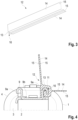
- eine Querschnittsansicht durch einen Abschnitt des Wärmetauschers;
- Fig. 3:
- die Dichtleiste des Wärmetauschers in einer perspektivischen Ansicht;
- Fig. 4:
- eine Querschnittsansicht durch einen Abschnitt eines erfindungsgemäßen Wärmetauschers gemäß einer zweiten Ausgestaltungsform; und
- Fig. 5:
- eine Querschnittsansicht durch einen Abschnitt eines erfindungsgemäßen Wärmetauschers gemäß einer dritten Ausgestaltungsform.
- In der
Fig. 1 ist eine beispielhafte Ausgestaltung eines erfindungsgemäßen Wärmetauschers dargestellt. - Der Wärmetauscher umfasst zwei länglich ausgebildete und parallel beabstandet zueinander ausgerichtete Wärmetauscherkästen 1 sowie ein zwischen den Wärmetauscherkästen 1 befindliches Wärmetauschernetz 2, das in den Zeichnungen vereinfacht dargestellt ist. Das Wärmetauschernetz 2 kann in bekannter Weise eine Mehrzahl von Wärmetauscherrohren 3, beispielsweise in Form von Flachrohren, umfassen, die sich in paralleler Ausrichtung zwischen den Wärmetauscherkästen 1 erstrecken und deren offene Enden in Innenräume der beiden Wärmetauscherkästen 1 münden. Endabschnitte der Wärmetauscherrohre können dazu durch Durchgangsöffnungen, die in jeweils einem Rohrboden 3 der beiden Wärmetauscherkästen 1 ausgebildet sind, geführt sein. Die Wärmetauscherkästen 1 umfassen jeweils neben einem der Rohrböden 3 ein wannenförmiges Gehäuse 4. Eine Verbindung zwischen den Rohrböden 3 und dem jeweils dazugehörigen Gehäuse 4 der beiden Wärmetauscherkästen 1 kann beispielsweise mittels einer Bördelverbindung realisiert sein.
- In die Wärmetauscherkästen 1 und konkret in die wannenförmigen Gehäuse 4 davon sind mindestens ein Einlass 5 und mindestens ein Auslass 6 für ein Wärmetauschfluid (insbesondere eine Wärmetauschflüssigkeit) integriert. In dem Ausgestaltungsbeispiel gemäß der
Fig. 1 ist der Wärmetauscher als Doppelwärmetauscher ausgestaltet, d.h. dieser umfasst zwei nebeneinander angeordnete Wärmetauscherteilnetze 2a, 2b, wobei die Wärmetauscherrohre der beiden Wärmetauscherteilnetze 2a, 2b in dieselben zwei Wärmetauscherkästen 1 münden. Dabei sind die Wärmetauscherkästen 1 jedoch zwischen den jeweils zwei Abschnitten, in die die Wärmetauscherrohre der verschiedenen Wärmetauscherteilnetze 2a, 2b münden, jeweils mittels einer Trennwand (nicht sichtbar) unterteilt. Demnach durchströmt das Wärmetauschfluid, das über einen ersten, oberen Einlass 5 eines ersten der Wärmetauscherkästen 1a einströmt, lediglich die Wärmetauscherrohre eines ersten, oberen der Wärmetauscherteilnetze 2a und wird über einen ersten, oberen Auslass 6, der in den zweiten Wärmetauscherkasten 1b integriert ist, wieder abgeführt. In gleicher Weise strömt ein anderer Teil des Wärmetauschfluids in einen zweiten, unteren Einlass 7 des ersten Wärmetauscherkastens 1a, durchströmt dann die Wärmetauscherrohre des zweiten, unteren Wärmetauschernetzes 2b und wird dann über einen zweiten, unteren Auslass 8 des zweiten Wärmetauscherkastens 1b abgeführt. - Ein Wärmeübergang von dem Wärmetauschfluid auf Kühlluft, die den Wärmetauscher durchströmt, erfolgt hauptsächlich im Bereich des Wärmetauschernetzes 2. um diesen Wärmeübergang zu optimieren können die Wärmetauscherrohre des Wärmetauschernetzes 2 vorzugsweise als Flachrohre ausgestaltet sein, wodurch diese ein relativ großes Verhältnis von umströmter Fläche zu durchströmtem Volumen aufweisen. Für eine weitere Verbesserung des Wärmeübergangs und auch für eine Verbesserung der strukturellen Stabilität des Wärmetauschers können in den Freiräumen, die zwischen den einzelnen Wärmetauscherrohren ausgebildet sind, Stützstrukturen in Form von sogenannten Wellrippen angeordnet sein. Hierbei kann es sich um mäanderförmig entlang der jeweils zwei angrenzenden Wärmetauscherrohre verlaufende Bleche handeln, die mit den Wärmetauscherrohren fest verbundenen, beispielsweise verlötet sind. Diese Stützstrukturen verbessern einen Wärmeübergang von dem Wärmetauschfluid auf die Kühlluft, indem sich diese durch den Kontakt mit den Wandungen der Wärmetauscherrohre erwärmen und so die für einen Wärmetausch mit der Kühlluft zur Verfügung stehende Fläche vergrößern. Für eine möglichst hohe Wärmeleitfähigkeit bei gleichzeitig möglichst geringen Herstellungskosten kann das gesamte Wärmetauschernetz 2 vorzugsweise aus Metall, beispielsweise aus Aluminiumblech, ausgestaltet sein.
- Der Wärmetauscher umfasst weiterhin noch zwei Begrenzungselemente 9, die jeweils in Form einer Profilleiste ausgestaltet sind und die das Wärmetauschernetz 2 an den beiden Rändern, die sich zwischen den beiden Wärmetauscherkästen 1 erstrecken, begrenzen. Dadurch wird unter anderem die strukturelle Stabilität des Wärmetauschers verbessert. Die Begrenzungselemente 9 sind dabei sowohl mit dem Wärmetauschernetz 2 als auch mit den beiden Wärmetauscherkästen 1 fest verbunden, beispielsweise verlötet.
- Gemäß den
Fig. 2 ,4 und5 können die Begrenzungselemente 9 unterschiedliche Querschnittsflächenformen aufweisen, wobei jeweils eine in etwa U-förmige Querschnittsfläche vorliegt, so dass sich für die Begrenzungselemente 9 jeweils grundsätzlich die Form einer Rinne ergibt. Dadurch ist mit einem relativ geringen Materialeinsatz und damit auch einem relativ geringen Gewicht eine relativ hohe Steifigkeit der Begrenzungselemente 9 und damit eine entsprechend gute strukturelle Stabilität des Wärmetauschers realisierbar. Bei dem Wärmetauscher gemäß denFig. 2 umfasst eine der beiden Seitenwände 9a der einzelnen Begrenzungselemente 9 an ihrer Längskante zwei entgegengesetzt seitlich verlaufende Fortsätze 10, wodurch sich ein T-rohrförmiger Abschnitt der Querschnittfläche dieser Seitenwand 9a ergibt. Unterhalb des außen gelegenen Fortsatzes 10 ist ein weiterer Fortsatz 10 vorgesehen, der sich ebenfalls, d.h. wie die beiden an der Längskanten gelegenen Fortsätze 10, über die gesamte Längserstreckung des jeweiligen Befestigungselements 9 erstreckt. Die beiden außen gelegenen Fortsätze 10 verlaufen dabei in Querrichtung geneigt, wobei sich diese einander annähern. Dadurch begrenzen diese einen im Querschnitt in etwa trapezförmigen Spalt. - Der T-förmige Abschnitt der einen Seitenwand 9a stellt einen Verbindungsabschnitt 11 des Begrenzungselements dar, der zur Anordnung innerhalb eines entsprechend T-förmig ausgebildeten Aufnahmeraums 16, der innerhalb eines Verbindungsabschnitts 13 einer Dichtleiste 12 vorliegt, vorgesehen ist. Dadurch ist eine formschlüssige Verbindung zwischen dem Begrenzungselement 9 und der Dichtleiste 12 realisiert, wobei diese formschlüssige Verbindung durch eine Relativbewegung zwischen der Dichtleiste 12 und dem Begrenzungselement 9 beziehungsweise durch ein Aufschieben der Dichtleiste 12 auf den Verbindungsabschnitt 11 des Begrenzungselements 9 in Längsrichtung beziehungsweise entlang der Längserstreckungen des Begrenzungselements 9 sowie der Dichtleiste 12 ausgebildet wird.
- Die Dichtleiste 12 des Wärmetauschers gemäß der
Fig. 2 umfasst neben dem Verbindungsabschnitt 13 noch zwei Dichtlippen 14, deren zwei parallel zueinander verlaufende Großflächen 15 jeweils plan ausgebildet sind, wobei die Großflächen 15 der einen Dichtlippe 14 im Vergleich zu den Großflächen 15 der anderen Dichtlippe 14 nicht-parallel beziehungsweise in einem Winkel, der etwas größer als 90° ist, zueinander ausgerichtet sind. Ein erste dieser Dichtlippen 14, nämlich diejenige, die quer zu der Richtung der Durchströmung des Wärmetauschernetzes 2 mittels der Kühlluft verläuft, dient dazu, einen Spalt, der einerseits zwischen dem Begrenzungselement 9 beziehungsweise dem Wärmetauscher und andererseits einem den Wärmetauscher tragenden Rahmen (nicht dargestellt) ausgebildet ist, zu verschließen. Dadurch soll verhindert werden, dass Kühlluft, die für eine Durchströmung des Wärmetauschernetzes 2 vorgesehen ist, durch diesen Spalt strömt und dadurch das Wärmetauschernetz 2 umgeht. Die zweite dieser Dichtlippen 14 soll dagegen einen Spalt, der zwischen dem Wärmetauscher und einem sich daran anschließenden Gehäuse, beispielsweise dem Gehäuses eines Gebläses, verschließen, um durch eine möglichst leckagefreie Anbindung des Gebläses an den Wärmetauscher eine vorteilhafte Strömungsführung für die Kühlluft zu realisieren. - Die Dichtleiste 12 ist einstückig und materialeinheitlich aus beispielsweise EPDM ausgestaltet, wodurch sich eine kostengünstige Herstellbarkeit ergibt. Die konkrete Art der formschlüssigen Verbindung zwischen der Dichtleiste 12 und dem Begrenzungselement 9 beziehungsweise den Verbindungsabschnitten 11, 13 davon gewährleistet trotz der Elastizität der Dichtleiste 12 und damit auch des dazugehörigen Verbindungsabschnitts 13 eine sichere Verbindung mit dem Verbindungsabschnitt 11 des Begrenzungselements 9.
- Die in der
Fig. 4 dargestellte Ausgestaltungsform eines erfindungsgemäßen Wärmetauschers unterscheidet sich von derjenigen gemäß denFig. 1 bis 3 lediglich in der Ausgestaltung der Querschnittsformen des Begrenzungselements 9 und damit insbesondere auch des Verbindungsabschnitts 11 davon sowie in der daran angepassten Ausgestaltung des Verbindungsabschnitts 13 der Dichtleiste 12. Die Seitenwände 9a des Begrenzungselements 9 gemäß derFig. 4 weisen J-förmige Querschnittsflächen auf, so dass sich auch ein Verbindungsabschnitt 11 mit entsprechend J-förmiger Querschnittsfläche ergibt, der für eine Anordnung innerhalb eines Aufnahmeraums 16 des Verbindungsabschnitts 13 der Dichtleiste mit J-förmiger Öffnungsquerschnittsfläche vorgesehen ist. Dadurch liegt wiederum eine formschlüssige Verbindung zwischen den beiden Verbindungsabschnitten 11, 13 vor. Zur Ausbildung dieser formschlüssigen Verbindung kann die Dichtleiste 12 wiederum in Längsrichtung auf den Verbindungsabschnitt 11 des Begrenzungselements 9 aufgeschoben werden. Alternativ dazu besteht in diesem Fall auch die Möglichkeit, die Verbindung durch eine Teilrotation der Dichtleiste 12 (entgegen dem Uhrzeigersinn in derFig. 4 ) auszubilden, was aufgrund der Elastizität, den auch der Verbindungsabschnitt 13 der Dichtleiste 12 aufweist, möglich ist. - Die Dichtleiste 12 des Wärmetauschers gemäß der
Fig. 5 unterscheidet sich von demjenigen der anderen Wärmetauscher einerseits darin, dass lediglich eine Dichtlippe 14 vorgesehen ist. Diese erstreckt sich quer und insbesondere senkrecht zu der Richtung der Durchströmung des Wärmetauschernetzes 2 mittels der Kühlluft. Weiterhin weist der Verbindungsabschnitt 13 dieser Dichtleiste 12 T-förmige Querschnittsflächen auf, wobei dieser Verbindungsabschnitt 13 teilweise in einem Aufnahmeraum 17 des Begrenzungselements 9 mit T-förmiger Öffnungsquerschnittsfläche angeordnet ist. Dieser Aufnahmeraum 17 wird von einem Verbindungsabschnitt 11 des Begrenzungselements 9 ausgebildet, der innerhalb der Senke des rinnenförmigen Begrenzungselements 9 angeordnet ist und dabei an den Boden 9a des Begrenzungselements 9 angrenzt. Auch diese Dichtleiste 12 kann zur Ausbildung einer formschlüssigen Verbindung mit ihrem Verbindungsabschnitt 13 in den Aufnahmeraum 17 des Verbindungsabschnitts 11 des Begrenzungselements 9 auf- beziehungsweise eingeschoben werden. -
- 1
- Wärmetauscherkasten
- 1a
- erster Wärmetauscherkasten
- 1b
- zweiter Wärmetauscherkasten
- 2
- Wärmetauschernetz
- 2a
- erstes Wärmetauscherteilnetz
- 2b
- zweites Wärmetauscherteilnetz
- 3
- Rohrboden des Wärmetauscherkastens
- 4
- Gehäuse des Wärmetauscherkastens
- 5
- erster Einlass
- 6
- erster Auslass
- 7
- zweiter Einlass
- 8
- zweiter Auslass
- 9
- Begrenzungselement
- 9a
- Seitenwand des Begrenzungselements
- 9b
- Boden des Begrenzungselements
- 10
- Fortsatz
- 11
- Verbindungsabschnitt des Begrenzungselements
- 12
- Dichtleiste
- 13
- Verbindungsabschnitt der Dichtleiste
- 14
- Dichtlippe der Dichtleiste
- 15
- Großfläche der Dichtlippe
- 16
- Aufnahmeraum des Verbindungsabschnitts der Dichtleiste
- 17
- Aufnahmeraum des Verbindungsabschnitts des Begrenzungselements
Claims (9)
- Wärmetauscher für ein Kühlsystem eines Kraftfahrzeugs mit einem Wärmetauschernetz (2), das eine Mehrzahl von Fluidleitungen umfasst, die für eine Durchströmung mittels eines ersten Wärmetauschfluids und für eine Umströmung mittels eines zweiten Wärmetauschfluids eingerichtet sind, und mit einem Begrenzungselement (9), das das Wärmetauschernetz (2) an zumindest einer Seite begrenzt, wobei eine einstückige und aus einem elastischen Material ausgebildete Dichtleiste (12), die zumindest in einem Abschnitt der Längserstreckung entlang des Begrenzungselements (9) verläuft, vorgesehen ist, wobei die Dichtleiste (12) einen Verbindungsabschnitt (13), der formschlüssig mit einem Verbindungsabschnitt (11) des Begrenzungselements (9) verbunden ist, und mindestens eine Dichtlippe (14), die zumindest in einem Abschnitt der Längserstreckung entlang des Verbindungsabschnitts (13) der Dichtleiste (12) verläuft, aufweist, dadurch gekennzeichnet, dass von den Verbindungsabschnitten (11, 13) der Dichtleiste (12) und des Begrenzungselements (9) einer einen Abschnitt mit T-, L- oder J-förmiger Querschnittsfläche aufweist, der in einem Aufnahmeraum mit T-, L- oder J-förmiger Öffnungsquerschnittsfläche des anderen Verbindungsabschnitts (11, 13) aufgenommen ist.
- Wärmetauscher gemäß Anspruch 1, dadurch gekennzeichnet, dass die Dichtlippe (14) entlang der gesamten Längserstreckung des Verbindungsabschnitts (13) der Dichtleiste (12) verläuft.
- Wärmetauscher gemäß einem der vorhergehenden Ansprüche, dadurch gekennzeichnet, dass zumindest eine Großfläche (15) der Dichtlippe (14) plan ausgebildet ist.
- Wärmetauscher gemäß Anspruch 3, gekennzeichnet durch mindestens zwei Dichtlippen (14), die jeweils mindestens eine plane Großfläche (15) aufweisen, wobei die planen Großflächen (15) der verschiedenen Dichtlippen (14) bezüglich ihrer Querstreckungen nicht-parallel zueinander ausgerichtet sind.
- Wärmetauscher gemäß einem der vorhergehenden Ansprüche, gekennzeichnet durch eine Ausgestaltung der formschlüssigen Verbindung zwischen den Verbindungsabschnitten (11, 13) der Dichtleiste (12) und des Begrenzungselements (9) derart, dass diese durch eine Relativbewegung der Verbindungsabschnitte (11, 13) entlang ihrer Längserstreckungen ausgebildet werden kann.
- Wärmetauscher gemäß einem der vorhergehenden Ansprüche, gekennzeichnet durch einen oder zwei Wärmetauscherkästen (1), der/die zumindest einen Einlass (5, 7) und einen Auslass (6, 8) für ein Wärmetauschfluid aufweisen, wobei der Wärmetauscherkasten (1) oder die Wärmetauscherkästen (1) das Wärmetauschernetz (2) (jeweils) an einer Seite begrenzt/begrenzen.
- Wärmetauscher gemäß Anspruch 6, dadurch gekennzeichnet, dass der Wärmetauscherkasten (1) oder einer der Wärmetauscherkästen (1) das Begrenzungselement (9) ist oder umfasst.
- Wärmetauscher gemäß Anspruch 6, dadurch gekennzeichnet, dass (jeweils) ein längsaxiales Ende des Begrenzungselements (9) an den Wärmetauscherkasten (1) oder an die Wärmetauscherkästen (1) angrenzt.
- Kombination eines Wärmetauschers gemäß einem der vorhergehenden Ansprüche und einer zumindest an das Begrenzungselement (9) angrenzenden Struktur, wobei zwischen dem Begrenzungselement (9) und der Struktur ein Spalt ausgebildet ist, der zumindest teilweise durch die Dichtlippe (14) der Dichtleiste (12) verschlossen ist.
Applications Claiming Priority (1)
| Application Number | Priority Date | Filing Date | Title |
|---|---|---|---|
| DE102021101772.6A DE102021101772A1 (de) | 2021-01-27 | 2021-01-27 | Wärmetauscher mit Dichtleiste |
Publications (2)
| Publication Number | Publication Date |
|---|---|
| EP4035918A1 EP4035918A1 (de) | 2022-08-03 |
| EP4035918B1 true EP4035918B1 (de) | 2024-08-28 |
Family
ID=79601596
Family Applications (1)
| Application Number | Title | Priority Date | Filing Date |
|---|---|---|---|
| EP22151436.7A Active EP4035918B1 (de) | 2021-01-27 | 2022-01-13 | Wärmetauscher mit dichtleiste |
Country Status (2)
| Country | Link |
|---|---|
| EP (1) | EP4035918B1 (de) |
| DE (1) | DE102021101772A1 (de) |
Families Citing this family (1)
| Publication number | Priority date | Publication date | Assignee | Title |
|---|---|---|---|---|
| EP4556838A1 (de) * | 2023-11-15 | 2025-05-21 | Valeo Systemes Thermiques | Dichtung für einen kondensator |
Family Cites Families (6)
| Publication number | Priority date | Publication date | Assignee | Title |
|---|---|---|---|---|
| JP2007283824A (ja) | 2006-04-13 | 2007-11-01 | Calsonic Kansei Corp | 熱交換器のシール構造 |
| KR101184208B1 (ko) * | 2006-04-14 | 2012-09-19 | 한라공조주식회사 | 열교환기 |
| GB2532768B (en) * | 2014-11-27 | 2018-01-10 | Mahle Int Gmbh | Evaporator seal |
| US11137212B2 (en) | 2016-06-23 | 2021-10-05 | Hanon Systems | Bypass seal for plate heater matrix |
| FR3056736B1 (fr) | 2016-09-28 | 2019-07-26 | Valeo Systemes Thermiques | Faisceau d’echange thermique pour echangeur thermique, echangeur thermique et procede d’assemblage associes |
| PL3315890T3 (pl) * | 2016-10-27 | 2020-12-14 | Valeo Autosystemy Sp. Z.O.O. | Uszczelnienie powietrzne do samochodowego wymiennika ciepła |
-
2021
- 2021-01-27 DE DE102021101772.6A patent/DE102021101772A1/de active Pending
-
2022
- 2022-01-13 EP EP22151436.7A patent/EP4035918B1/de active Active
Also Published As
| Publication number | Publication date |
|---|---|
| EP4035918A1 (de) | 2022-08-03 |
| DE102021101772A1 (de) | 2022-07-28 |
Similar Documents
| Publication | Publication Date | Title |
|---|---|---|
| EP1654508B2 (de) | Wärmeübertrager sowie verfahren zu dessen herstellung | |
| EP0964218B1 (de) | Wärmetauscher mit verrippten Flachrohren, insbesondere Heizungswärmetauscher, Motorkühler, Verflüssiger oder Verdampfer, für Kraftfahrzeuge | |
| DE60319986T2 (de) | Plattenwärmetauscher | |
| EP2567423B1 (de) | Batteriekühler | |
| EP2021717B1 (de) | Wärmetauscher für kraftfahrzeuge | |
| DE102009055715A1 (de) | Saugrohr mit integriertem Ladeluftkühler | |
| EP2906893A1 (de) | Wärmetauscher | |
| EP2962056B1 (de) | Wärmeübertrager | |
| EP1491837A2 (de) | Wärmetauscher in gehäuseloser Plattenbauweise | |
| EP1714098B1 (de) | Anordnung zweier wärmeübertrager | |
| EP4035918B1 (de) | Wärmetauscher mit dichtleiste | |
| DE102009002998A1 (de) | Kraftfahrzeug-Kühleinrichtung und Kühlsystem | |
| EP2710318A1 (de) | Lamellenwärmeübertrager | |
| EP1757888B1 (de) | Anordnung zweier Wärmeübertrager | |
| DE102007052888A1 (de) | Wärmeübertrager, insbesondere für ein Fahrzeug | |
| DE69404108T2 (de) | Wärmetauscher, insbesondere als Ölkühler benutzt | |
| DE19547928C2 (de) | Plattenwärmetauscher | |
| DE10297468T5 (de) | Lamelle für ein Wärmetauschermodul für insbesondere ein Kraftfahrzeug | |
| DE102004049670B4 (de) | Kraftstoffkühler, Kraftfahrzeug mit einem derartigen Kraftstoffkühler | |
| DE102009056274A1 (de) | Wärmetauscher | |
| DE19702440A1 (de) | Kraftstoffkühler | |
| DE112022000999T5 (de) | Wärmetauscher | |
| DE102006017610B4 (de) | Wärmetauscher zur Ladeluftkühlung für Kraftfahrzeuge, System | |
| EP1853868A1 (de) | Kasten zur aufnahme eines fluids für einen wärmeübertrager, wärmeübertrager, insbesondere für eine wärmeübertragereinheit, wärmeübertragereinheit, insbesondere in ausführung als monoblock | |
| EP1522810A2 (de) | Wärmeübertrager für ein Kraftfahrzeug, insbesondere Kühlmittel/Luft-Kühler |
Legal Events
| Date | Code | Title | Description |
|---|---|---|---|
| PUAI | Public reference made under article 153(3) epc to a published international application that has entered the european phase |
Free format text: ORIGINAL CODE: 0009012 |
|
| STAA | Information on the status of an ep patent application or granted ep patent |
Free format text: STATUS: THE APPLICATION HAS BEEN PUBLISHED |
|
| AK | Designated contracting states |
Kind code of ref document: A1 Designated state(s): AL AT BE BG CH CY CZ DE DK EE ES FI FR GB GR HR HU IE IS IT LI LT LU LV MC MK MT NL NO PL PT RO RS SE SI SK SM TR |
|
| STAA | Information on the status of an ep patent application or granted ep patent |
Free format text: STATUS: REQUEST FOR EXAMINATION WAS MADE |
|
| 17P | Request for examination filed |
Effective date: 20230203 |
|
| RBV | Designated contracting states (corrected) |
Designated state(s): AL AT BE BG CH CY CZ DE DK EE ES FI FR GB GR HR HU IE IS IT LI LT LU LV MC MK MT NL NO PL PT RO RS SE SI SK SM TR |
|
| GRAP | Despatch of communication of intention to grant a patent |
Free format text: ORIGINAL CODE: EPIDOSNIGR1 |
|
| STAA | Information on the status of an ep patent application or granted ep patent |
Free format text: STATUS: GRANT OF PATENT IS INTENDED |
|
| INTG | Intention to grant announced |
Effective date: 20240618 |
|
| GRAS | Grant fee paid |
Free format text: ORIGINAL CODE: EPIDOSNIGR3 |
|
| GRAA | (expected) grant |
Free format text: ORIGINAL CODE: 0009210 |
|
| STAA | Information on the status of an ep patent application or granted ep patent |
Free format text: STATUS: THE PATENT HAS BEEN GRANTED |
|
| AK | Designated contracting states |
Kind code of ref document: B1 Designated state(s): AL AT BE BG CH CY CZ DE DK EE ES FI FR GB GR HR HU IE IS IT LI LT LU LV MC MK MT NL NO PL PT RO RS SE SI SK SM TR |
|
| REG | Reference to a national code |
Ref country code: CH Ref legal event code: EP |
|
| REG | Reference to a national code |
Ref country code: DE Ref legal event code: R096 Ref document number: 502022001528 Country of ref document: DE |
|
| REG | Reference to a national code |
Ref country code: IE Ref legal event code: FG4D Free format text: LANGUAGE OF EP DOCUMENT: GERMAN |
|
| P01 | Opt-out of the competence of the unified patent court (upc) registered |
Free format text: CASE NUMBER: APP_58974/2024 Effective date: 20241029 |
|
| REG | Reference to a national code |
Ref country code: LT Ref legal event code: MG9D |
|
| PG25 | Lapsed in a contracting state [announced via postgrant information from national office to epo] |
Ref country code: NO Free format text: LAPSE BECAUSE OF FAILURE TO SUBMIT A TRANSLATION OF THE DESCRIPTION OR TO PAY THE FEE WITHIN THE PRESCRIBED TIME-LIMIT Effective date: 20241128 |
|
| PG25 | Lapsed in a contracting state [announced via postgrant information from national office to epo] |
Ref country code: FI Free format text: LAPSE BECAUSE OF FAILURE TO SUBMIT A TRANSLATION OF THE DESCRIPTION OR TO PAY THE FEE WITHIN THE PRESCRIBED TIME-LIMIT Effective date: 20240828 Ref country code: PT Free format text: LAPSE BECAUSE OF FAILURE TO SUBMIT A TRANSLATION OF THE DESCRIPTION OR TO PAY THE FEE WITHIN THE PRESCRIBED TIME-LIMIT Effective date: 20241230 Ref country code: NL Free format text: LAPSE BECAUSE OF FAILURE TO SUBMIT A TRANSLATION OF THE DESCRIPTION OR TO PAY THE FEE WITHIN THE PRESCRIBED TIME-LIMIT Effective date: 20240828 Ref country code: GR Free format text: LAPSE BECAUSE OF FAILURE TO SUBMIT A TRANSLATION OF THE DESCRIPTION OR TO PAY THE FEE WITHIN THE PRESCRIBED TIME-LIMIT Effective date: 20241129 Ref country code: PL Free format text: LAPSE BECAUSE OF FAILURE TO SUBMIT A TRANSLATION OF THE DESCRIPTION OR TO PAY THE FEE WITHIN THE PRESCRIBED TIME-LIMIT Effective date: 20240828 |
|
| PG25 | Lapsed in a contracting state [announced via postgrant information from national office to epo] |
Ref country code: BG Free format text: LAPSE BECAUSE OF FAILURE TO SUBMIT A TRANSLATION OF THE DESCRIPTION OR TO PAY THE FEE WITHIN THE PRESCRIBED TIME-LIMIT Effective date: 20240828 |
|
| PG25 | Lapsed in a contracting state [announced via postgrant information from national office to epo] |
Ref country code: LV Free format text: LAPSE BECAUSE OF FAILURE TO SUBMIT A TRANSLATION OF THE DESCRIPTION OR TO PAY THE FEE WITHIN THE PRESCRIBED TIME-LIMIT Effective date: 20240828 |
|
| REG | Reference to a national code |
Ref country code: NL Ref legal event code: MP Effective date: 20240828 |
|
| PG25 | Lapsed in a contracting state [announced via postgrant information from national office to epo] |
Ref country code: IS Free format text: LAPSE BECAUSE OF FAILURE TO SUBMIT A TRANSLATION OF THE DESCRIPTION OR TO PAY THE FEE WITHIN THE PRESCRIBED TIME-LIMIT Effective date: 20241228 |
|
| PG25 | Lapsed in a contracting state [announced via postgrant information from national office to epo] |
Ref country code: HR Free format text: LAPSE BECAUSE OF FAILURE TO SUBMIT A TRANSLATION OF THE DESCRIPTION OR TO PAY THE FEE WITHIN THE PRESCRIBED TIME-LIMIT Effective date: 20240828 |
|
| PG25 | Lapsed in a contracting state [announced via postgrant information from national office to epo] |
Ref country code: RS Free format text: LAPSE BECAUSE OF FAILURE TO SUBMIT A TRANSLATION OF THE DESCRIPTION OR TO PAY THE FEE WITHIN THE PRESCRIBED TIME-LIMIT Effective date: 20241128 Ref country code: ES Free format text: LAPSE BECAUSE OF FAILURE TO SUBMIT A TRANSLATION OF THE DESCRIPTION OR TO PAY THE FEE WITHIN THE PRESCRIBED TIME-LIMIT Effective date: 20240828 |
|
| PG25 | Lapsed in a contracting state [announced via postgrant information from national office to epo] |
Ref country code: RS Free format text: LAPSE BECAUSE OF FAILURE TO SUBMIT A TRANSLATION OF THE DESCRIPTION OR TO PAY THE FEE WITHIN THE PRESCRIBED TIME-LIMIT Effective date: 20241128 Ref country code: PT Free format text: LAPSE BECAUSE OF FAILURE TO SUBMIT A TRANSLATION OF THE DESCRIPTION OR TO PAY THE FEE WITHIN THE PRESCRIBED TIME-LIMIT Effective date: 20241230 Ref country code: PL Free format text: LAPSE BECAUSE OF FAILURE TO SUBMIT A TRANSLATION OF THE DESCRIPTION OR TO PAY THE FEE WITHIN THE PRESCRIBED TIME-LIMIT Effective date: 20240828 Ref country code: NO Free format text: LAPSE BECAUSE OF FAILURE TO SUBMIT A TRANSLATION OF THE DESCRIPTION OR TO PAY THE FEE WITHIN THE PRESCRIBED TIME-LIMIT Effective date: 20241128 Ref country code: NL Free format text: LAPSE BECAUSE OF FAILURE TO SUBMIT A TRANSLATION OF THE DESCRIPTION OR TO PAY THE FEE WITHIN THE PRESCRIBED TIME-LIMIT Effective date: 20240828 Ref country code: LV Free format text: LAPSE BECAUSE OF FAILURE TO SUBMIT A TRANSLATION OF THE DESCRIPTION OR TO PAY THE FEE WITHIN THE PRESCRIBED TIME-LIMIT Effective date: 20240828 Ref country code: IS Free format text: LAPSE BECAUSE OF FAILURE TO SUBMIT A TRANSLATION OF THE DESCRIPTION OR TO PAY THE FEE WITHIN THE PRESCRIBED TIME-LIMIT Effective date: 20241228 Ref country code: HR Free format text: LAPSE BECAUSE OF FAILURE TO SUBMIT A TRANSLATION OF THE DESCRIPTION OR TO PAY THE FEE WITHIN THE PRESCRIBED TIME-LIMIT Effective date: 20240828 Ref country code: GR Free format text: LAPSE BECAUSE OF FAILURE TO SUBMIT A TRANSLATION OF THE DESCRIPTION OR TO PAY THE FEE WITHIN THE PRESCRIBED TIME-LIMIT Effective date: 20241129 Ref country code: FI Free format text: LAPSE BECAUSE OF FAILURE TO SUBMIT A TRANSLATION OF THE DESCRIPTION OR TO PAY THE FEE WITHIN THE PRESCRIBED TIME-LIMIT Effective date: 20240828 Ref country code: ES Free format text: LAPSE BECAUSE OF FAILURE TO SUBMIT A TRANSLATION OF THE DESCRIPTION OR TO PAY THE FEE WITHIN THE PRESCRIBED TIME-LIMIT Effective date: 20240828 Ref country code: BG Free format text: LAPSE BECAUSE OF FAILURE TO SUBMIT A TRANSLATION OF THE DESCRIPTION OR TO PAY THE FEE WITHIN THE PRESCRIBED TIME-LIMIT Effective date: 20240828 |
|
| PGFP | Annual fee paid to national office [announced via postgrant information from national office to epo] |
Ref country code: DE Payment date: 20250131 Year of fee payment: 4 |
|
| PG25 | Lapsed in a contracting state [announced via postgrant information from national office to epo] |
Ref country code: SM Free format text: LAPSE BECAUSE OF FAILURE TO SUBMIT A TRANSLATION OF THE DESCRIPTION OR TO PAY THE FEE WITHIN THE PRESCRIBED TIME-LIMIT Effective date: 20240828 Ref country code: DK Free format text: LAPSE BECAUSE OF FAILURE TO SUBMIT A TRANSLATION OF THE DESCRIPTION OR TO PAY THE FEE WITHIN THE PRESCRIBED TIME-LIMIT Effective date: 20240828 Ref country code: RO Free format text: LAPSE BECAUSE OF FAILURE TO SUBMIT A TRANSLATION OF THE DESCRIPTION OR TO PAY THE FEE WITHIN THE PRESCRIBED TIME-LIMIT Effective date: 20240828 |
|
| PG25 | Lapsed in a contracting state [announced via postgrant information from national office to epo] |
Ref country code: EE Free format text: LAPSE BECAUSE OF FAILURE TO SUBMIT A TRANSLATION OF THE DESCRIPTION OR TO PAY THE FEE WITHIN THE PRESCRIBED TIME-LIMIT Effective date: 20240828 |
|
| PGFP | Annual fee paid to national office [announced via postgrant information from national office to epo] |
Ref country code: AT Payment date: 20250417 Year of fee payment: 4 |
|
| PG25 | Lapsed in a contracting state [announced via postgrant information from national office to epo] |
Ref country code: CZ Free format text: LAPSE BECAUSE OF FAILURE TO SUBMIT A TRANSLATION OF THE DESCRIPTION OR TO PAY THE FEE WITHIN THE PRESCRIBED TIME-LIMIT Effective date: 20240828 |
|
| PGFP | Annual fee paid to national office [announced via postgrant information from national office to epo] |
Ref country code: FR Payment date: 20250127 Year of fee payment: 4 |
|
| PG25 | Lapsed in a contracting state [announced via postgrant information from national office to epo] |
Ref country code: SK Free format text: LAPSE BECAUSE OF FAILURE TO SUBMIT A TRANSLATION OF THE DESCRIPTION OR TO PAY THE FEE WITHIN THE PRESCRIBED TIME-LIMIT Effective date: 20240828 Ref country code: IT Free format text: LAPSE BECAUSE OF FAILURE TO SUBMIT A TRANSLATION OF THE DESCRIPTION OR TO PAY THE FEE WITHIN THE PRESCRIBED TIME-LIMIT Effective date: 20240828 |
|
| REG | Reference to a national code |
Ref country code: DE Ref legal event code: R097 Ref document number: 502022001528 Country of ref document: DE |
|
| PLBE | No opposition filed within time limit |
Free format text: ORIGINAL CODE: 0009261 |
|
| STAA | Information on the status of an ep patent application or granted ep patent |
Free format text: STATUS: NO OPPOSITION FILED WITHIN TIME LIMIT |
|
| 26N | No opposition filed |
Effective date: 20250530 |
|
| REG | Reference to a national code |
Ref country code: CH Ref legal event code: PL |
|
| PG25 | Lapsed in a contracting state [announced via postgrant information from national office to epo] |
Ref country code: SE Free format text: LAPSE BECAUSE OF FAILURE TO SUBMIT A TRANSLATION OF THE DESCRIPTION OR TO PAY THE FEE WITHIN THE PRESCRIBED TIME-LIMIT Effective date: 20240828 |
|
| PG25 | Lapsed in a contracting state [announced via postgrant information from national office to epo] |
Ref country code: MC Free format text: LAPSE BECAUSE OF FAILURE TO SUBMIT A TRANSLATION OF THE DESCRIPTION OR TO PAY THE FEE WITHIN THE PRESCRIBED TIME-LIMIT Effective date: 20240828 Ref country code: LU Free format text: LAPSE BECAUSE OF NON-PAYMENT OF DUE FEES Effective date: 20250113 |
|
| PG25 | Lapsed in a contracting state [announced via postgrant information from national office to epo] |
Ref country code: BE Free format text: LAPSE BECAUSE OF NON-PAYMENT OF DUE FEES Effective date: 20250131 |
|
| PG25 | Lapsed in a contracting state [announced via postgrant information from national office to epo] |
Ref country code: CH Free format text: LAPSE BECAUSE OF NON-PAYMENT OF DUE FEES Effective date: 20250131 |
|
| REG | Reference to a national code |
Ref country code: BE Ref legal event code: MM Effective date: 20250131 |