EP4035884B1 - Vorrichtung zur herstellung von verpackungsmaterial und verfahren zur verwendung davon - Google Patents
Vorrichtung zur herstellung von verpackungsmaterial und verfahren zur verwendung davon Download PDFInfo
- Publication number
- EP4035884B1 EP4035884B1 EP22151423.5A EP22151423A EP4035884B1 EP 4035884 B1 EP4035884 B1 EP 4035884B1 EP 22151423 A EP22151423 A EP 22151423A EP 4035884 B1 EP4035884 B1 EP 4035884B1
- Authority
- EP
- European Patent Office
- Prior art keywords
- paper
- rollers
- reciprocating blade
- blade
- packaging material
- Prior art date
- Legal status (The legal status is an assumption and is not a legal conclusion. Google has not performed a legal analysis and makes no representation as to the accuracy of the status listed.)
- Active
Links
Images


Classifications
-
- B—PERFORMING OPERATIONS; TRANSPORTING
- B31—MAKING ARTICLES OF PAPER, CARDBOARD OR MATERIAL WORKED IN A MANNER ANALOGOUS TO PAPER; WORKING PAPER, CARDBOARD OR MATERIAL WORKED IN A MANNER ANALOGOUS TO PAPER
- B31D—MAKING ARTICLES OF PAPER, CARDBOARD OR MATERIAL WORKED IN A MANNER ANALOGOUS TO PAPER, NOT PROVIDED FOR IN SUBCLASSES B31B OR B31C
- B31D5/00—Multiple-step processes for making three-dimensional [3D] articles
- B31D5/0039—Multiple-step processes for making three-dimensional [3D] articles for making dunnage or cushion pads
- B31D5/0043—Multiple-step processes for making three-dimensional [3D] articles for making dunnage or cushion pads including crumpling flat material
- B31D5/0047—Multiple-step processes for making three-dimensional [3D] articles for making dunnage or cushion pads including crumpling flat material involving toothed wheels
-
- B—PERFORMING OPERATIONS; TRANSPORTING
- B31—MAKING ARTICLES OF PAPER, CARDBOARD OR MATERIAL WORKED IN A MANNER ANALOGOUS TO PAPER; WORKING PAPER, CARDBOARD OR MATERIAL WORKED IN A MANNER ANALOGOUS TO PAPER
- B31D—MAKING ARTICLES OF PAPER, CARDBOARD OR MATERIAL WORKED IN A MANNER ANALOGOUS TO PAPER, NOT PROVIDED FOR IN SUBCLASSES B31B OR B31C
- B31D5/00—Multiple-step processes for making three-dimensional [3D] articles
- B31D5/0039—Multiple-step processes for making three-dimensional [3D] articles for making dunnage or cushion pads
- B31D5/0043—Multiple-step processes for making three-dimensional [3D] articles for making dunnage or cushion pads including crumpling flat material
- B31D5/0052—Multiple-step processes for making three-dimensional [3D] articles for making dunnage or cushion pads including crumpling flat material involving rollers
-
- B—PERFORMING OPERATIONS; TRANSPORTING
- B31—MAKING ARTICLES OF PAPER, CARDBOARD OR MATERIAL WORKED IN A MANNER ANALOGOUS TO PAPER; WORKING PAPER, CARDBOARD OR MATERIAL WORKED IN A MANNER ANALOGOUS TO PAPER
- B31D—MAKING ARTICLES OF PAPER, CARDBOARD OR MATERIAL WORKED IN A MANNER ANALOGOUS TO PAPER, NOT PROVIDED FOR IN SUBCLASSES B31B OR B31C
- B31D5/00—Multiple-step processes for making three-dimensional [3D] articles
- B31D5/0039—Multiple-step processes for making three-dimensional [3D] articles for making dunnage or cushion pads
- B31D5/0069—Multiple-step processes for making three-dimensional [3D] articles for making dunnage or cushion pads including forming or transforming three-dimensional material, e.g. corrugated webs or material of cellular structure
-
- B—PERFORMING OPERATIONS; TRANSPORTING
- B31—MAKING ARTICLES OF PAPER, CARDBOARD OR MATERIAL WORKED IN A MANNER ANALOGOUS TO PAPER; WORKING PAPER, CARDBOARD OR MATERIAL WORKED IN A MANNER ANALOGOUS TO PAPER
- B31D—MAKING ARTICLES OF PAPER, CARDBOARD OR MATERIAL WORKED IN A MANNER ANALOGOUS TO PAPER, NOT PROVIDED FOR IN SUBCLASSES B31B OR B31C
- B31D2205/00—Multiple-step processes for making three-dimensional articles
- B31D2205/0005—Multiple-step processes for making three-dimensional articles for making dunnage or cushion pads
- B31D2205/0011—Multiple-step processes for making three-dimensional articles for making dunnage or cushion pads including particular additional operations
- B31D2205/0017—Providing stock material in a particular form
- B31D2205/0023—Providing stock material in a particular form as web from a roll
-
- B—PERFORMING OPERATIONS; TRANSPORTING
- B31—MAKING ARTICLES OF PAPER, CARDBOARD OR MATERIAL WORKED IN A MANNER ANALOGOUS TO PAPER; WORKING PAPER, CARDBOARD OR MATERIAL WORKED IN A MANNER ANALOGOUS TO PAPER
- B31D—MAKING ARTICLES OF PAPER, CARDBOARD OR MATERIAL WORKED IN A MANNER ANALOGOUS TO PAPER, NOT PROVIDED FOR IN SUBCLASSES B31B OR B31C
- B31D2205/00—Multiple-step processes for making three-dimensional articles
- B31D2205/0005—Multiple-step processes for making three-dimensional articles for making dunnage or cushion pads
- B31D2205/0011—Multiple-step processes for making three-dimensional articles for making dunnage or cushion pads including particular additional operations
- B31D2205/0047—Feeding, guiding or shaping the material
-
- B—PERFORMING OPERATIONS; TRANSPORTING
- B31—MAKING ARTICLES OF PAPER, CARDBOARD OR MATERIAL WORKED IN A MANNER ANALOGOUS TO PAPER; WORKING PAPER, CARDBOARD OR MATERIAL WORKED IN A MANNER ANALOGOUS TO PAPER
- B31D—MAKING ARTICLES OF PAPER, CARDBOARD OR MATERIAL WORKED IN A MANNER ANALOGOUS TO PAPER, NOT PROVIDED FOR IN SUBCLASSES B31B OR B31C
- B31D2205/00—Multiple-step processes for making three-dimensional articles
- B31D2205/0005—Multiple-step processes for making three-dimensional articles for making dunnage or cushion pads
- B31D2205/0011—Multiple-step processes for making three-dimensional articles for making dunnage or cushion pads including particular additional operations
- B31D2205/0058—Cutting; Individualising the final products
-
- B—PERFORMING OPERATIONS; TRANSPORTING
- B31—MAKING ARTICLES OF PAPER, CARDBOARD OR MATERIAL WORKED IN A MANNER ANALOGOUS TO PAPER; WORKING PAPER, CARDBOARD OR MATERIAL WORKED IN A MANNER ANALOGOUS TO PAPER
- B31D—MAKING ARTICLES OF PAPER, CARDBOARD OR MATERIAL WORKED IN A MANNER ANALOGOUS TO PAPER, NOT PROVIDED FOR IN SUBCLASSES B31B OR B31C
- B31D2205/00—Multiple-step processes for making three-dimensional articles
- B31D2205/0005—Multiple-step processes for making three-dimensional articles for making dunnage or cushion pads
- B31D2205/0011—Multiple-step processes for making three-dimensional articles for making dunnage or cushion pads including particular additional operations
- B31D2205/0064—Stabilizing the shape of the final product, e.g. by mechanical interlocking
Definitions
- the present invention relates generally to a packaging material forming apparatus and a method of producing packaging material and finds particular, although not exclusive, utility in producing lengths of paper cushioning material.
- the cutting mechanism used in this machine comprises a single reciprocating blade and a stationary blade, with the packaging material passing between the two blades. An entire width of the packaging material is then crushed and cut with each stroke of the single reciprocating blade. As such, the cutting mechanism is prone to jamming, since the entire width of the packaging material is cut by a single reciprocating blade.
- This large reciprocating blade also requires a heavy-duty motor, the size of which limits the compactness of the overall machine.
- Document GB 2 549 257 A discloses a dunnage forming machine comprising a cutting mechanism which comprises a stationary blade and a first and a second reciprocating blade, which blades are pivotable relative to the stationary blade.
- the blades being driven by drive cogs which are coupled such that they rotate concurrently, wherein the blades cut the dunnage at the same time.
- a smaller, lighter and more compact machine which has relatively simple construction and operation is desirable.
- the present invention provides packaging material forming apparatus for use with a feedstock of pre-folded paper having two substantially continuous linear sides provided in the form of a roll, the apparatus comprising a former for partially opening the folded paper into a linear tubular form, and first and second sets of corresponding rollers for moving the tubular paper form through the apparatus, wherein the first set of rollers is arranged to rotate at a speed greater than the second set of rollers to enable the tubular paper form to be partially crushed in a linear direction, the second set of rollers being arranged to crimp the two linear sides of the paper together, and wherein both of the rollers in the second set comprise teeth, the two sets of teeth being arranged to interlock and correspond with one another, the apparatus further comprising a cutting mechanism for cutting the partially crushed linear tubular paper form into desired lengths, wherein: the cutting mechanism comprises a stationary blade, a first reciprocating blade, and a second reciprocating blade; the first reciprocating blade and/or the second reciprocating blade are pivotable relative to the stationary blade;
- the pre-folded paper may have a width of 600mm (when unfolded), with one edge folded over 175mm from one linear side and the other edge folded over 175mm from the other opposite linear side such that the two edges overlap by 100mm.
- the paper may be initially folded flat having a width of 250mm.
- the roll of paper may be 300m long.
- the former may be inserted into the folded paper such that as the paper moves across the former, into the apparatus, the portions of paper forming the two side folds are pushed away from the base portion of the paper to create the tubular form.
- the first reciprocating blade and the second reciprocating blade may be arranged to cut a first portion and a second portion of a width of the partially crushed linear tubular paper form. In this way, the cutting mechanism may be less prone to jamming, because less force is exerted by the extruded paper form onto the cutting edges of the reciprocating blades.
- the first reciprocating blade and the second reciprocating blade may be arranged to cut in two distinct strokes. This may render a light duty motor suitable for driving the cutting mechanism, thereby minimising the size and weight of the cutting mechanism and consequently the packaging material forming apparatus.
- a portion of the width of the paper form cut by the first reciprocating blade may overlap with a portion of the width of the paper form cut by the second reciprocating blade, such that a portion of the width of the paper form may be cut by both blades.
- the first reciprocating blade and the second reciprocating blade may each have at least one sharp edge.
- Sharp may mean any profile effective for cutting the partially crushed linear tubular paper form. Sharp may mean that the at least one edge is a right angle.
- the use of right-angled blades may mean that minimal maintenance and/or sharpening is required, which may therefore increase the longevity of the cutting mechanism.
- the blades may be made from metal, for example flat ground machine steel.
- the second set of rollers may be arranged to produce the crimp along the middle of the partially crushed tubular paper form in the direction of feeding through the machine.
- This crimp or seal may be effected by the teeth squeezing the paper between them.
- the seal may be effected between the two linear edges of the paper and the base portion of the paper such that a cross-section of the resultant packaging material is an approximate figure of eight with two cushion-like forms, one either side of a crimped middle section.
- the apparatus may further comprise two rotatable rollers upon which the roll of paper may rest and rotate.
- the rollers may be freely rotatable.
- the apparatus may comprise a frame and either or both of the first and second set of rollers may be resiliently mounted to the frame such that they are movable relative to it to accommodate the irregularities of the tubular paper form.
- the resilience may be achieved by using springs or other such resilient mountings between brackets, retaining a shaft upon which the rollers are mounted, and the frame.
- the radial outer surfaces of both of the rollers in the first set may be milled.
- the term "milled” may mean a series of grooves, or a pattern of raised pimples. The milling may aid the initial feeding of the paper into the apparatus as it may more easily “grab” the end of the paper and pull it through. Furthermore, it may assist in maintaining the rate of entry of paper into the apparatus.
- the apparatus may further comprise a cowling being arranged to accept the paper after it has been fed through the former and direct it to between the first set of rollers which are located immediately downstream thereof; the cowling having sides which taper inwardly so as to reduce the width of the paper as it passes therethrough.
- the sides of the cowling are closer together at the downstream end compared to the upstream inlet to inwardly reduce the width of the tubular paper form to approximately 130 mm.
- the cowling may be funnel-shape.
- the paper may be cut between the stationary and reciprocating blades.
- the stationary blade may have at least one sharp edge. Sharp may mean any profile effective for cutting the partially crushed linear tubular paper form. Sharp may mean that the at least one edge is a right angle.
- the stationary blade may be made from metal, for example flat ground machine steel.
- the first reciprocating blade and/or the second reciprocating blade may be pivotable relative to the stationary blade.
- the cutting motion of the reciprocating blades may pivot from an outside edge of the paper form towards the centre of the paper form, thereby resembling a scissor action.
- each reciprocating blade may incrementally cut the paper form from an outside edge towards the centre, leading to reduced force on the cutting mechanism and a lower likelihood of jamming.
- the second reciprocating blade may move linearly relative to the stationary blade, such that the second reciprocating blade may incrementally cut the paper form from an outside edge of the paper form towards the centre of the paper form.
- the first reciprocating blade may move linearly relative to the stationary blade, such that the first reciprocating blade may incrementally cut the paper form from an outside edge of the paper form towards the centre of the paper form.
- Motion of the first drive cog may be transferred to the first reciprocating blade via a first crank and first connecting rod
- motion of the second drive cog may be transferred to the second reciprocating blade via a second crank and second connecting rod
- each blade may be staggered by varying degrees.
- the staggering of the cutting action may be varied to suit the particular type of packaging material being produced.
- Removable may mean that the drive belt may be partially, or entirely removable from the drive cogs.
- Adjustable may mean that the drive belt may be extendable, such that the drive cogs may be rotated independently of one another while the drive belt is extended in position. The drive belt may then be retractable such that it retracts back to fitting around the drive cogs once adjustment is complete.
- the first reciprocating blade, the second reciprocating blade and the stationary blade may each have a cutting edge, and the cutting edges of the first reciprocating blade and the second reciprocating blade may be arranged immediately adjacent to the cutting edge of the stationary blade. In this way, the movement of the reciprocating blades across the edge of the stationary blade may create a shearing action, thereby effectively cutting the partially crushed linear tubular paper form therebetween.
- the resultant packaging material may be dispensed via a dispensing chute. This may be located downstream of the cutting mechanism.
- the apparatus may further comprise sensing means for sensing the presence or absence of packaging material in the chute, and a PCU for controlling the first and second sets of rollers and the cutting mechanism.
- the PCU may control the first and second sets of rollers by controlling a drive motor.
- the PCU may be programmed to stop the first and second sets of rollers before operating the cutting mechanism.
- the PCU may operate the first and second of rollers to produce packaging material when the sensor senses the absence of packaging material in the dispensing chute.
- the apparatus may not be producing packaging material when the sensor senses the presence of packaging material in the chute. In this way, a user may withdraw each length of packaging material, as required, without having to manually control the apparatus and without the apparatus producing more packaging than is immediately necessary.
- the apparatus may produce packaging material on demand and as required.
- the PCU may be programmed to produce a predetermined number of individual lengths of packaging material; the dimension of each length also being predetermined.
- the PCU may be programmed and the apparatus arranged such that a user is presented with various lengths to choose from and/or various numbers of lengths to select.
- the apparatus may include buttons assigned with these choices for ease of operability.
- the invention provides a method of producing packaging material comprising the steps of providing a packaging material forming apparatus according to the first aspect; providing a roll of pre-folded paper; feeding the free end of the paper through the former and between the first set of rollers; the former partially opening the folded paper into a linear tubular form, and operating the apparatus such that the first set of rollers rotate at a speed greater than the second set of rollers to enable the tubular paper form to be partially crushed in a linear direction, the second set of rollers being arranged to crimp the two linear sides of the paper together; and cutting the partially crushed linear tubular paper form into desired lengths.
- the two outside corners of the free end of the roll of pre-folded paper may be cut-off prior to being fed through the former and between the first set of rollers such that the free end of the paper is separated into three separate sheets.
- a packaging material forming apparatus may be provided for use with a feedstock of pre-folded paper having two substantially continuous linear sides provided in the form of a roll, the apparatus comprising a former for partially opening the folded paper into a linear tubular form, and first and second sets of corresponding rollers for moving the tubular paper form through the apparatus, wherein the first set of rollers is arranged to rotate at a speed greater than the second set of rollers to enable the tubular paper form to be partially crushed in a linear direction, the second set of rollers being arranged to crimp the two linear sides of the paper together, and wherein both of the rollers in the second set comprise teeth, the two sets of teeth being arranged to interlock and correspond with one another, the apparatus further comprising a cutting mechanism for cutting the partially crushed linear tubular paper form into desired lengths, wherein the cutting mechanism comprises a pivotable reciprocating blade and a fixed cutting surface.
- packaging material forming apparatus may be operated using the same method as described in relation to the second aspect. It will be understood that the features described with regard to the first and second aspects may equally be used with, and/or apply to, the packaging forming apparatus.
- the fixed cutting surface may be a planar and/or profiled sheet of material positioned substantially adjacent to the pivotable reciprocating blade, such that the paper form is arranged to pass between the pivotable reciprocating blade and the fixed cutting surface before the paper form is cut.
- the fixed cutting surface may be a stationary blade.
- first, second, third and the like in the description and in the claims are used for distinguishing between similar elements and not necessarily for describing a sequence, either temporally, spatially, in ranking or in any other manner. It is to be understood that the terms so used are interchangeable under appropriate circumstances and that operation is capable in other sequences than described or illustrated herein.
- top, bottom, over, under and the like in the description and the claims are used for descriptive purposes and not necessarily for describing relative positions. It is to be understood that the terms so used are interchangeable under appropriate circumstances and that operation is capable in other orientations than described or illustrated herein.
- FIG. 1 an apparatus 10 for producing packaging material, or dunnage, using a rugation process, from paper or similar material, is shown in schematic form.
- the figure does not include all of the various elements such as electric motors, instead showing only the key features.
- a frame 20 includes a support 40 at one upper end for holding a pre-folded roll of paper 30.
- the roll may rotate on an axle (not shown) passing through its centre, the axle being supported by the support 40.
- the roll of paper may rest on parallel rollers (not shown) without a central axle/spindle. This improves the ease with which the roll of paper may be replaced.
- An end of the paper 35 is led from the roll 30 over two individual tensioning rollers 50 so that the paper 35 may be fed horizontally into the main part 200 of the apparatus. Before it enters this main part 200 it passes between two further rollers 60 acting as guides.
- the paper then passes through and around a former 80 which expands the pre-folded paper 35 from a substantially flat web into a substantially linear tubular form.
- the former is described with reference to Figures 4 and 5 in more detail below.
- the substantially tubular form has a base 36 and two sides 37, 38 which extend from the base 35 up, around and over the base to form the sides and top of the tubular form.
- the linear centre of the tubular form of paper 35 then passes between two rollers 100 which squeeze together the top and bottom surfaces of the centre of the tubular form to create two cushion-like forms either side of a substantially flat compressed strip running in the direction of the linear length of the paper 110.
- the rollers 100 may be more wheel-like in form having a thickness in the range of 10mm to 20mm and a diameter in the range of 100mm to 200mm.
- the outer circumferential surface of the rollers may be milled or include dimples.
- the rollers may comprise metal.
- the paper 35 is propelled through this first set of rollers 100 at a speed in the range of 10 to 50 metres per minute.
- the paper 110 then passes between a second set of rollers which are rotating at a speed approximately half the speed of rotation of the first set of rollers such that the paper exits the second set of rollers in the range 5 to 25 metres per minute.
- Each of the second set of rollers 120 includes teeth, the two sets of teeth interlocking during rotation.
- the teeth are rounded in a sinusoidal manner so that they do not puncture, rip or tear the paper.
- the interaction of the two sets of teeth help to seal the central, previously compressed, strip such that it does not separate.
- the second set of rollers 120 may have a thickness in the range of 20mm to 50mm and a diameter in the range of 100mm to 200mm.
- the rollers may comprise metal.
- the resultant paper form 130 is thus comprised of linearly crumpled paper having two cushion-like forms either side of a central compressed and sealed strip.
- This dunnage 130 may then be cut into required length by a cutting mechanism 140, described in more detail below.
- the dunnage 130 may be used as packaging to prevent goods from being damaged in transit.
- the resultant paper may be dispensed via a dispensing chute (not shown) provided downstream of the cutting mechanism.
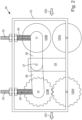
- FIG. 2 shows the main part 20 of the apparatus comprising a frame 23.
- the paper 35 enters the apparatus in the direction 200 on the right and exits on the left in the direction 201.
- the frame supports a lower first roller 100A and a lower second roller 120A.
- a support 24 extends from approximately the centre of the lower part of the frame 23 upwardly and a pivot point is provided towards the top thereof. From this pivot point 27, two arms 28 extend one rearwardly towards the first set of rollers 100 and one forwardly towards the second set of rollers 120.
- the upper first roller 100B is pivotally connected.
- the upper second roller 120B is pivotally connected.
- These upper first 100B and second 120B rollers may thus move up and down relative to the fixed lower first 100A and second 120A rollers. This movement allows for the crumpled paper 110 to pass through the second set of rollers 120A, 120B without blocking occurring.
- the upper first 100B and second 120B rollers are biased downwardly against the upper side of the frame 23 by individual coil springs 29 the force of each being adjustable via a threaded bar 25 as will be understood by the skilled person. This ensures good traction between the upper and lower rollers.
- a motor is used to drive the rollers.
- a gear system may be employed to drive the first and second sets of rollers at different speeds.
- Figure 3 shows a cross-section of the pre-folded paper 35. It comprises a single laminar sheet wherein the two longitudinal edges have been folded over the central portion 36. One edge has been folded over initially and then the other folded over such that an upper portion 38 overlies a middle portion 37 which, in turn, overlies the lower portion 36.
- the figure shows the paper slightly opened for the sake of clarity. In reality the paper 35 will feed off the roll 30 with tight folds such that the upper portion 38 will be substantially immediately above and on the middle portion 37 which will be substantially immediately above and on the lower portion 36.
- Figures 4 and 5 show the former 80 which is used to open the folded paper into an approximate tubular form.
- the former 80 comprises two lobes 81, 82, located one at either end of a first rectilinear bar 83.
- the lobes 81, 82 each comprise a cylinder with a dome shape at either longitudinal end.
- a second rectilinear bar 84 is provided extending from one lobe 81 towards the other lob 82, parallel with, but slightly spaced from the first rectilinear bar 83.
- This second bar 84 does not extend all the way to the lobe 82. Rather, it turns through 90 degrees and extends upwardly 85.
- This upwardly extending bar is only partially shown in Figure 4 . The direction of its extent is indicated by broken lines.
- the upwardly extending bar 85 is located closer to the lobe 82 than the lobe 81 from which it extends. This allows for upwardly extending bar 85 to be located approximately at the position of the longitudinal edge of the upper portion 38 of paper.
- the former 80 is arranged such that the direction of the movement of the paper 35 as it passes past the former 80 is substantially perpendicular to the axis of the two rectilinear bars 83, 84.
- the paper 35 passes the former such that the lower portion 36 passes underneath the first rectilinear bar 83, the middle portion 37 passes between the first and second rectilinear bars 83, 84, and the upper portion 38 passes over the upper second rectilinear bar 84.
- the former is positioned inside the folded paper 35 such that as the paper passes past the former 80 the two lobes move the paper into an approximate tubular form 90.
- the upwardly extending bar 85 allows the paper to pass it by extending beyond the longitudinal edge of the upper portion 38 as may be more clearly seen in Figure 5 .
- the resultant tubular form of paper 90 includes enlarged cushion like forms 33, 34 each around the lobes 81, 82.
- FIG. 6 a partial view of one example of the apparatus including a cutting mechanism 140 is shown.
- the cutting mechanism 140 comprises a first reciprocating blade 310, a second reciprocating blade 320 and a stationary blade 330.
- the stationary blade 330 extends substantially horizontally across an upper portion of the cutting mechanism 140, from a left-hand side of the cutting mechanism 140 to a right-hand side of the cutting mechanism 140.
- the first reciprocating blade 310 is pivotally mounted adjacent to the stationary blade 330 at a pivot point 340 located near the left-hand edge of the stationary blade 330.
- the second reciprocating blade 320 is pivotally mounted adjacent to the stationary blade 330 at a pivot point 350 located near the right-hand edge of the stationary blade 330.
- the first 310 and second 320 reciprocating blades each include a pivot point 340, 350, thereby pivotally mounting them to the pivot points 340, 350.
- Each blade comprises a cutting edge 315, 325 on its upper surface arranged to pass over the stationary cutting blade 330.
- the stationary blade 330 has a cutting edge 335 along its lower edge.
- the first reciprocating blade 310 and second reciprocating blade 320 may move toward and away from the stationary blade 330 such that the finished crumpled dunnage which passes between the blades parallel to the cutting edge 335 of stationary blade 330 is cut into desired lengths.
- Each drive cog includes a crank, arranged as a pin 365, 385, extending from the face of each drive cog 365.
- Connecting rods 360, 380 are arranged to connect each drive cog 370, 390 via their respective cranks 365, 385 to each respective blade 310, 320.
- Each connecting rod 360, 380 is pivotably attached to each blade. Accordingly, in use, as each drive cog rotates, each connecting rod is driven up and down reciprocatively to thus move each blade 310, 320 up and down reciprocatively so that they partially rotate back and forth about their pivot points 340, 350. This movement ensures that the cutting edge 315, 325 of each pivotable blade 310, 320 moves across, and against, the cutting edge 330 of the stationary blade to thereby cut the paper emerging from withing the apparatus. It will be understood that the cut starts at both outer edges of the crimped paper and travels towards the centre.
- each pivotable blade 310, 320 has a length that is at least as long, or longer, than half the width of the paper at the point of being cut such that the cutting edges 315, 325 may overlap, in use.
- the speed of reciprocation of the blades is arranged such that the blades do not impede the flow of crimped paper from the machine. However, it is also contemplated that the motion of the paper may be stopped briefly while it is cut.
- Either or both of the drive cogs 370, 390 are driven by a motor (not shown), which may be the same motor as which drives the first 100 and second 120 sets of rollers.
- the drive cogs 370, 390 are shown coupled together via drive belt 395, although it is to be understood that if both drive cogs are driven no drive belt is required.
- the drive belt 395 includes an interior ribbed profile corresponding to an exterior toothed profile on each of the drive cogs 370, 390. In this way, the drive belt 395 connects the two drive cogs 370, 390 such that they may rotate in unison. The rotation of the drive cogs 370, 390.
- the relative rotational position of the drive cogs 370, 390 may be varied by removing the drive belt 395, rotating one or both of the drive cogs 370, 390, and replacing the drive belt 395. In this way, an offset may be introduced between the pivoting cutting action of the first reciprocating blade 310 and the second reciprocating blade 320.
- the drive belt 395 may be extendable, thereby allowing for adjustment of the offset between the rotational position of the drive cogs 370, 390 by extending the drive belt 395 to separate its ribs from the teeth on the drive cogs 370, 390, and rotating one or both of the drive cogs 370, 390 to a different relative position.
- the drive belt 395 may then be retractable such that it retracts back so its ribs again engage with the teeth on the drive cogs 370, 390 once adjustment is complete.
- the drive belt 395 is supported at its lower edge by a support roller 400.
- the first 100 and second 120 sets of rollers may be stopped when the cutting mechanism is required to cut the paper.
- only one cutting blade may be provided (not shown).
- This single blade is provided with a length such that it extends across the entire width of the paper as it emerges.
- the single blade may reciprocate, and be driven to reciprocate, in the same manner as described above with regard to the two blade alternative.
Landscapes
- Making Paper Articles (AREA)
- Auxiliary Devices For And Details Of Packaging Control (AREA)
Claims (12)
- Vorrichtung zum Formen von Verpackungsmaterial zur Verwendung mit einem Ausgangsmaterial aus vorgefaltetem Papier, das in Form einer Rolle zwei im Wesentlichen kontinuierlich lineare Seiten aufweist, wobei die Vorrichtung einen Former (80) zum teilweisen Öffnen des gefalteten Papiers in eine lineare, röhrenförmige Form umfasst, sowie erste und zweite Sätze von entsprechenden Walzen (100, 120) zum Bewegen der röhrenförmigen Papierform durch die Vorrichtung, wobei der erste Satz von Walzen (100) so angeordnet ist, dass er sich mit einer höheren Geschwindigkeit dreht als der zweite Satz von Walzen (120), um die röhrenförmige Papierform in linearer Richtung teilweise zu zerdrücken, wobei der zweite Satz von Walzen (120) so angeordnet ist, dass er die beiden linearen Seiten des Papiers zusammenfaltet, und wobei beide Walzen (100, 120) im zweiten Satz Zähne aufweisen, die beiden Zahnreihen so angeordnet sind, dass sie ineinandergreifen und miteinander korrespondieren, und die Vorrichtung ferner einen Schneidmechanismus (140) zum Schneiden der teilweise zerdrückten linearen, röhrenförmigen Papierform in gewünschte Längen umfasst, wobei:der Schneidmechanismus (140) eine stationäre Klinge (330), eine erste hin- und herbewegliche Klinge (310) und eine zweite hin- und herbewegliche Klinge (320) umfasst;die erste hin- und herbewegliche Klinge (330) und die zweite hin- und herbewegliche Klinge (320) relativ zur stationären Klinge (330) schwenkbar sind;die erste hin- und herbewegliche Klinge (310) durch ein erstes Antriebsrad (370) angetrieben wird unddie zweite hin- und herbewegliche Klinge (320) durch ein zweites Antriebsrad (390) angetrieben wird;das erste Antriebsrad (370) und das zweite Antriebsrad (390) so gekoppelt sind, dass sie gleichzeitig rotieren; unddie Kopplung des ersten Antriebsrads (370) und des zweiten Antriebsrads (390) über einen Antriebsriemen (395) erfolgt, und der Antriebsriemen (395) abnehmbar und/oder einstellbar ist, so dass das erste Antriebsrad (370) und das zweite Antriebsrad (390) unabhängig voneinander gedreht werden können, wodurch eine Phasendifferenz zwischen der Bewegung der ersten Verbindungstange (360) und der zweiten Verbindungstange (380) ermöglicht wird, wodurch eine Phasendifferenz zwischen der Bewegung der ersten hin- und herbeweglichen Klinge (310) und der zweiten hin- und herbeweglichen Klinge (320) verändert werden kann.
- Vorrichtung nach Anspruch 1, wobei der zweite Satz von Walzen (120) so angeordnet ist, dass er die Faltung entlang der Mitte der teilweise zerdrückten röhrenförmigen Papierform in der Vorschubrichtung durch die Maschine erzeugt.
- Vorrichtung nach einem der vorhergehenden Ansprüche, weiter umfassend zwei drehbare Walzen, auf denen die Papierrolle ruhen und rotieren kann.
- Vorrichtung nach einem der vorhergehenden Ansprüche, umfassend einen Rahmen (20) und wobei entweder oder beide der ersten und zweiten Sätze von Walzen (100, 120) federnd an dem Rahmen (20) montiert sind, so dass sie relativ zu ihm beweglich sind, um Unregelmäßigkeiten der röhrenförmigen Papierform aufzunehmen.
- Vorrichtung nach Anspruch 1, weiter umfassend eine Verkleidung, die so angeordnet ist, dass sie das Papier, nachdem es durch den Former (80) geführt wurde, aufnimmt und es zwischen die unmittelbar stromabwärts davon befindlichen ersten Walzen (100) leitet; die Verkleidung hat Seiten, die sich verjüngen, um die Breite des Papiers zu reduzieren, während es hindurchgeht.
- Vorrichtung nach Anspruch 1, wobei die Bewegung des ersten Antriebsrads (370) über eine erste Kurbel (365) und eine erste Verbindungstange (360) auf die erste hin- und herbewegliche Klinge (310) übertragen wird, und die Bewegung des zweiten Antriebsrads (390) über eine zweite Kurbel (385) und eine zweite Verbindungstange (380) auf die zweite hin- und herbewegliche Klinge (320) übertragen wird.
- Vorrichtung nach einem der vorhergehenden Ansprüche, wobei die erste hin- und herbewegliche Klinge (310), die zweite hin- und herbewegliche Klinge (320) und die stationäre Klinge (330) jeweils eine Schneide (315, 325, 335) aufweisen, und die Schneiden (315, 325) der ersten hin- und herbeweglichen Klinge (310) und der zweiten hin- und herbeweglichen Klinge (320) unmittelbar an die Schneide (335) der stationären Klinge (330) angrenzen.
- Vorrichtung nach einem der vorhergehenden Ansprüche, weiter umfassend eine Sensoreinrichtung zum Erkennen des Vorhandenseins oder Fehlens von Verpackungsmaterial in einem Ausgabeschacht, und eine PCU zur Steuerung der ersten und zweiten Sätze von Walzen (100, 120) und des Schneidmechanismus (140).
- Vorrichtung nach Anspruch 8, wobei die PCU die ersten und zweiten Sätze von Walzen (100, 120) betreibt, um Verpackungsmaterial zu produzieren, wenn der Sensor das Fehlen von Verpackungsmaterial im Ausgabeschacht erkennt.
- Vorrichtung nach einem der Ansprüche 8 und 9, wobei die PCU so programmiert ist, dass sie eine vorbestimmte Anzahl von individuellen Längen von Verpackungsmaterial produziert; die Dimension jeder Länge ist ebenfalls vorbestimmt.
- Ein Verfahren zur Herstellung von Verpackungsmaterial, umfassend die Schritte des Bereitstellens einer Vorrichtung zum Formen von Verpackungsmaterial gemäß einem der vorhergehenden Ansprüche; Bereitstellen einer Rolle aus vorgefaltetem Papier; Zuführen des freien Endes des Papiers durch den Former (80) und zwischen die ersten Walzen (100); der Former (80) öffnet das gefaltete Papier teilweise zu einer linearen, röhrenförmigen Form, und Betreiben der Vorrichtung, so dass der erste Satz von Walzen (100) sich mit einer höheren Geschwindigkeit dreht als der zweite Satz von Walzen (120), um die röhrenförmige Papierform in linearer Richtung teilweise zu zerdrücken, wobei der zweite Satz von Walzen (120) so angeordnet ist, dass er die beiden linearen Seiten des Papiers zusammenfaltet; und das Schneiden der teilweise zerdrückten linearen, röhrenförmigen Papierform in gewünschte Längen.
- Verfahren nach Anspruch 11, wobei die beiden äußeren Ecken des freien Endes der Rolle des vorgefalteten Papiers abgeschnitten werden, bevor sie durch den Former (80) und zwischen die ersten Walzen (100) geführt werden, so dass das freie Ende des Papiers in drei separate Blätter getrennt wird.
Applications Claiming Priority (1)
| Application Number | Priority Date | Filing Date | Title |
|---|---|---|---|
| GB2101404.8A GB2603199B (en) | 2021-02-02 | 2021-02-02 | Packaging material forming apparatus, and method of using the same |
Publications (3)
| Publication Number | Publication Date |
|---|---|
| EP4035884A1 EP4035884A1 (de) | 2022-08-03 |
| EP4035884B1 true EP4035884B1 (de) | 2025-05-07 |
| EP4035884C0 EP4035884C0 (de) | 2025-05-07 |
Family
ID=74865196
Family Applications (1)
| Application Number | Title | Priority Date | Filing Date |
|---|---|---|---|
| EP22151423.5A Active EP4035884B1 (de) | 2021-02-02 | 2022-01-13 | Vorrichtung zur herstellung von verpackungsmaterial und verfahren zur verwendung davon |
Country Status (3)
| Country | Link |
|---|---|
| EP (1) | EP4035884B1 (de) |
| ES (1) | ES3032950T3 (de) |
| GB (1) | GB2603199B (de) |
Families Citing this family (1)
| Publication number | Priority date | Publication date | Assignee | Title |
|---|---|---|---|---|
| CN115958842A (zh) * | 2022-12-06 | 2023-04-14 | 许昌裕同印刷包装有限公司 | 包装盒成型装置以及成型方法 |
Family Cites Families (3)
| Publication number | Priority date | Publication date | Assignee | Title |
|---|---|---|---|---|
| EP0721392B1 (de) * | 1993-08-20 | 2000-02-23 | Ranpak Corp. | Polsterumwandlungsmaschine, ausgerüstet mit einem zusammenbau zum schneiden und ausrichten |
| GB2508267B (en) * | 2013-09-16 | 2015-01-07 | Dan Steedman | Packaging material forming apparatus, and method of using the same |
| GB2549257B (en) * | 2016-03-31 | 2018-04-11 | Easypack Ltd | Dunnage forming machine |
-
2021
- 2021-02-02 GB GB2101404.8A patent/GB2603199B/en active Active
-
2022
- 2022-01-13 ES ES22151423T patent/ES3032950T3/es active Active
- 2022-01-13 EP EP22151423.5A patent/EP4035884B1/de active Active
Also Published As
| Publication number | Publication date |
|---|---|
| EP4035884A1 (de) | 2022-08-03 |
| GB202101404D0 (en) | 2021-03-17 |
| ES3032950T3 (en) | 2025-07-29 |
| GB2603199A (en) | 2022-08-03 |
| EP4035884C0 (de) | 2025-05-07 |
| GB2603199B (en) | 2023-04-19 |
Similar Documents
| Publication | Publication Date | Title |
|---|---|---|
| GB2508267A (en) | Dunnage forming apparatus | |
| DE602004006993T2 (de) | Schneidwerk für eine hülsen-wickelmaschine mit einem an einem rotierendem arm geführten schneider | |
| CN104495486B (zh) | 自动削棉机 | |
| CA2351264C (en) | Machine for repeatedly folding a sheet of foil to create a layered edge | |
| DE2436717A1 (de) | Schlitz- und falzvorrichtung fuer durchlaufende materialbahnen | |
| CN212503244U (zh) | 一种无纺布用分切装置 | |
| EP4035884B1 (de) | Vorrichtung zur herstellung von verpackungsmaterial und verfahren zur verwendung davon | |
| US20100011924A1 (en) | Corrugating apparatus | |
| CN212042921U (zh) | 一种纵剪机的进料机构 | |
| CN109162084A (zh) | 一种高效布料裁剪装置 | |
| EP3278957B1 (de) | Tragbare tischschweissmaschine | |
| CN103931689A (zh) | 一种双线双刀刀切馒头机 | |
| US5692440A (en) | Cutting device | |
| CN103538290A (zh) | 用于对纸板坯开槽的设备 | |
| CN102501539B (zh) | 保温板的封装设备 | |
| US4096724A (en) | Method of coiling a flat strip | |
| CN213052984U (zh) | 一种板材分割废料收集装置 | |
| US12275159B2 (en) | Perforating device and converting machine comprising said device | |
| CN212653503U (zh) | 一种干巾擦片切片机 | |
| CN118418233B (zh) | 一种果丹皮切割成卷接料装置 | |
| US20100012265A1 (en) | Discharge device | |
| CN212602063U (zh) | 一种全自动口罩生产线上的切边机构 | |
| CN115352937A (zh) | 一种薄膜输送结构及薄膜压合装置 | |
| DE202017102617U1 (de) | Schneideinrichtung zum Schneiden eines Endlosbands, insbesondere eines Stahl- oder Textilcordbands | |
| CN116872557B (zh) | 一种可对纸箱边角料处理裁剪的折叠成型装置 |
Legal Events
| Date | Code | Title | Description |
|---|---|---|---|
| PUAI | Public reference made under article 153(3) epc to a published international application that has entered the european phase |
Free format text: ORIGINAL CODE: 0009012 |
|
| STAA | Information on the status of an ep patent application or granted ep patent |
Free format text: STATUS: THE APPLICATION HAS BEEN PUBLISHED |
|
| AK | Designated contracting states |
Kind code of ref document: A1 Designated state(s): AL AT BE BG CH CY CZ DE DK EE ES FI FR GB GR HR HU IE IS IT LI LT LU LV MC MK MT NL NO PL PT RO RS SE SI SK SM TR |
|
| STAA | Information on the status of an ep patent application or granted ep patent |
Free format text: STATUS: REQUEST FOR EXAMINATION WAS MADE |
|
| 17P | Request for examination filed |
Effective date: 20230103 |
|
| RBV | Designated contracting states (corrected) |
Designated state(s): AL AT BE BG CH CY CZ DE DK EE ES FI FR GB GR HR HU IE IS IT LI LT LU LV MC MK MT NL NO PL PT RO RS SE SI SK SM TR |
|
| RAP1 | Party data changed (applicant data changed or rights of an application transferred) |
Owner name: PROTEGA GLOBAL LIMITED |
|
| GRAP | Despatch of communication of intention to grant a patent |
Free format text: ORIGINAL CODE: EPIDOSNIGR1 |
|
| STAA | Information on the status of an ep patent application or granted ep patent |
Free format text: STATUS: GRANT OF PATENT IS INTENDED |
|
| INTG | Intention to grant announced |
Effective date: 20250109 |
|
| RIN1 | Information on inventor provided before grant (corrected) |
Inventor name: STEEDMAN, DAN |
|
| RBV | Designated contracting states (corrected) |
Designated state(s): AL AT BE BG CH CY CZ DE DK EE ES FI FR GR HR HU IE IS IT LI LT LU LV MC MK MT NL NO PL PT RO RS SE SI SK SM TR |
|
| GRAS | Grant fee paid |
Free format text: ORIGINAL CODE: EPIDOSNIGR3 |
|
| GRAA | (expected) grant |
Free format text: ORIGINAL CODE: 0009210 |
|
| STAA | Information on the status of an ep patent application or granted ep patent |
Free format text: STATUS: THE PATENT HAS BEEN GRANTED |
|
| AK | Designated contracting states |
Kind code of ref document: B1 Designated state(s): AL AT BE BG CH CY CZ DE DK EE ES FI FR GR HR HU IE IS IT LI LT LU LV MC MK MT NL NO PL PT RO RS SE SI SK SM TR |
|
| REG | Reference to a national code |
Ref country code: CH Ref legal event code: EP |
|
| REG | Reference to a national code |
Ref country code: DE Ref legal event code: R096 Ref document number: 602022014059 Country of ref document: DE |
|
| REG | Reference to a national code |
Ref country code: IE Ref legal event code: FG4D |
|
| U01 | Request for unitary effect filed |
Effective date: 20250530 |
|
| U07 | Unitary effect registered |
Designated state(s): AT BE BG DE DK EE FI FR IT LT LU LV MT NL PT RO SE SI Effective date: 20250610 |
|
| REG | Reference to a national code |
Ref country code: ES Ref legal event code: FG2A Ref document number: 3032950 Country of ref document: ES Kind code of ref document: T3 Effective date: 20250729 |
|
| PG25 | Lapsed in a contracting state [announced via postgrant information from national office to epo] |
Ref country code: NO Free format text: LAPSE BECAUSE OF FAILURE TO SUBMIT A TRANSLATION OF THE DESCRIPTION OR TO PAY THE FEE WITHIN THE PRESCRIBED TIME-LIMIT Effective date: 20250807 Ref country code: GR Free format text: LAPSE BECAUSE OF FAILURE TO SUBMIT A TRANSLATION OF THE DESCRIPTION OR TO PAY THE FEE WITHIN THE PRESCRIBED TIME-LIMIT Effective date: 20250808 |
|
| PG25 | Lapsed in a contracting state [announced via postgrant information from national office to epo] |
Ref country code: PL Free format text: LAPSE BECAUSE OF FAILURE TO SUBMIT A TRANSLATION OF THE DESCRIPTION OR TO PAY THE FEE WITHIN THE PRESCRIBED TIME-LIMIT Effective date: 20250507 |
|
| PG25 | Lapsed in a contracting state [announced via postgrant information from national office to epo] |
Ref country code: HR Free format text: LAPSE BECAUSE OF FAILURE TO SUBMIT A TRANSLATION OF THE DESCRIPTION OR TO PAY THE FEE WITHIN THE PRESCRIBED TIME-LIMIT Effective date: 20250507 |
|
| PG25 | Lapsed in a contracting state [announced via postgrant information from national office to epo] |
Ref country code: RS Free format text: LAPSE BECAUSE OF FAILURE TO SUBMIT A TRANSLATION OF THE DESCRIPTION OR TO PAY THE FEE WITHIN THE PRESCRIBED TIME-LIMIT Effective date: 20250807 |
|
| PG25 | Lapsed in a contracting state [announced via postgrant information from national office to epo] |
Ref country code: IS Free format text: LAPSE BECAUSE OF FAILURE TO SUBMIT A TRANSLATION OF THE DESCRIPTION OR TO PAY THE FEE WITHIN THE PRESCRIBED TIME-LIMIT Effective date: 20250907 |
|
| U20 | Renewal fee for the european patent with unitary effect paid |
Year of fee payment: 5 Effective date: 20251126 |
|
| PG25 | Lapsed in a contracting state [announced via postgrant information from national office to epo] |
Ref country code: SM Free format text: LAPSE BECAUSE OF FAILURE TO SUBMIT A TRANSLATION OF THE DESCRIPTION OR TO PAY THE FEE WITHIN THE PRESCRIBED TIME-LIMIT Effective date: 20250507 |
|
| PG25 | Lapsed in a contracting state [announced via postgrant information from national office to epo] |
Ref country code: CZ Free format text: LAPSE BECAUSE OF FAILURE TO SUBMIT A TRANSLATION OF THE DESCRIPTION OR TO PAY THE FEE WITHIN THE PRESCRIBED TIME-LIMIT Effective date: 20250507 |
|
| PG25 | Lapsed in a contracting state [announced via postgrant information from national office to epo] |
Ref country code: SK Free format text: LAPSE BECAUSE OF FAILURE TO SUBMIT A TRANSLATION OF THE DESCRIPTION OR TO PAY THE FEE WITHIN THE PRESCRIBED TIME-LIMIT Effective date: 20250507 |
|
| REG | Reference to a national code |
Ref country code: CH Ref legal event code: U11 Free format text: ST27 STATUS EVENT CODE: U-0-0-U10-U11 (AS PROVIDED BY THE NATIONAL OFFICE) Effective date: 20260201 |
|
| PLBE | No opposition filed within time limit |
Free format text: ORIGINAL CODE: 0009261 |
|
| STAA | Information on the status of an ep patent application or granted ep patent |
Free format text: STATUS: NO OPPOSITION FILED WITHIN TIME LIMIT |
|
| REG | Reference to a national code |
Ref country code: CH Ref legal event code: L10 Free format text: ST27 STATUS EVENT CODE: U-0-0-L10-L00 (AS PROVIDED BY THE NATIONAL OFFICE) Effective date: 20260318 |