EP4034800B1 - Procédé de réparation d'une paroi de cuve de transport et/ou de stockage de gaz naturel liquéfié - Google Patents
Procédé de réparation d'une paroi de cuve de transport et/ou de stockage de gaz naturel liquéfié Download PDFInfo
- Publication number
- EP4034800B1 EP4034800B1 EP20790376.6A EP20790376A EP4034800B1 EP 4034800 B1 EP4034800 B1 EP 4034800B1 EP 20790376 A EP20790376 A EP 20790376A EP 4034800 B1 EP4034800 B1 EP 4034800B1
- Authority
- EP
- European Patent Office
- Prior art keywords
- reinforcement
- sleeve
- membrane
- reinforcements
- tank wall
- Prior art date
- Legal status (The legal status is an assumption and is not a legal conclusion. Google has not performed a legal analysis and makes no representation as to the accuracy of the status listed.)
- Active
Links
Images




Classifications
-
- B—PERFORMING OPERATIONS; TRANSPORTING
- B63—SHIPS OR OTHER WATERBORNE VESSELS; RELATED EQUIPMENT
- B63B—SHIPS OR OTHER WATERBORNE VESSELS; EQUIPMENT FOR SHIPPING
- B63B81/00—Repairing or maintaining vessels
-
- B—PERFORMING OPERATIONS; TRANSPORTING
- B63—SHIPS OR OTHER WATERBORNE VESSELS; RELATED EQUIPMENT
- B63B—SHIPS OR OTHER WATERBORNE VESSELS; EQUIPMENT FOR SHIPPING
- B63B25/00—Load-accommodating arrangements, e.g. stowing, trimming; Vessels characterised thereby
- B63B25/02—Load-accommodating arrangements, e.g. stowing, trimming; Vessels characterised thereby for bulk goods
- B63B25/08—Load-accommodating arrangements, e.g. stowing, trimming; Vessels characterised thereby for bulk goods fluid
- B63B25/12—Load-accommodating arrangements, e.g. stowing, trimming; Vessels characterised thereby for bulk goods fluid closed
- B63B25/16—Load-accommodating arrangements, e.g. stowing, trimming; Vessels characterised thereby for bulk goods fluid closed heat-insulated
-
- F—MECHANICAL ENGINEERING; LIGHTING; HEATING; WEAPONS; BLASTING
- F17—STORING OR DISTRIBUTING GASES OR LIQUIDS
- F17C—VESSELS FOR CONTAINING OR STORING COMPRESSED, LIQUEFIED OR SOLIDIFIED GASES; FIXED-CAPACITY GAS-HOLDERS; FILLING VESSELS WITH, OR DISCHARGING FROM VESSELS, COMPRESSED, LIQUEFIED, OR SOLIDIFIED GASES
- F17C13/00—Details of vessels or of the filling or discharging of vessels
- F17C13/004—Details of vessels or of the filling or discharging of vessels for large storage vessels not under pressure
-
- F—MECHANICAL ENGINEERING; LIGHTING; HEATING; WEAPONS; BLASTING
- F17—STORING OR DISTRIBUTING GASES OR LIQUIDS
- F17C—VESSELS FOR CONTAINING OR STORING COMPRESSED, LIQUEFIED OR SOLIDIFIED GASES; FIXED-CAPACITY GAS-HOLDERS; FILLING VESSELS WITH, OR DISCHARGING FROM VESSELS, COMPRESSED, LIQUEFIED, OR SOLIDIFIED GASES
- F17C3/00—Vessels not under pressure
-
- F—MECHANICAL ENGINEERING; LIGHTING; HEATING; WEAPONS; BLASTING
- F17—STORING OR DISTRIBUTING GASES OR LIQUIDS
- F17C—VESSELS FOR CONTAINING OR STORING COMPRESSED, LIQUEFIED OR SOLIDIFIED GASES; FIXED-CAPACITY GAS-HOLDERS; FILLING VESSELS WITH, OR DISCHARGING FROM VESSELS, COMPRESSED, LIQUEFIED, OR SOLIDIFIED GASES
- F17C2201/00—Vessel construction, in particular geometry, arrangement or size
- F17C2201/01—Shape
- F17C2201/0147—Shape complex
- F17C2201/0157—Polygonal
-
- F—MECHANICAL ENGINEERING; LIGHTING; HEATING; WEAPONS; BLASTING
- F17—STORING OR DISTRIBUTING GASES OR LIQUIDS
- F17C—VESSELS FOR CONTAINING OR STORING COMPRESSED, LIQUEFIED OR SOLIDIFIED GASES; FIXED-CAPACITY GAS-HOLDERS; FILLING VESSELS WITH, OR DISCHARGING FROM VESSELS, COMPRESSED, LIQUEFIED, OR SOLIDIFIED GASES
- F17C2201/00—Vessel construction, in particular geometry, arrangement or size
- F17C2201/05—Size
- F17C2201/052—Size large (>1000 m3)
-
- F—MECHANICAL ENGINEERING; LIGHTING; HEATING; WEAPONS; BLASTING
- F17—STORING OR DISTRIBUTING GASES OR LIQUIDS
- F17C—VESSELS FOR CONTAINING OR STORING COMPRESSED, LIQUEFIED OR SOLIDIFIED GASES; FIXED-CAPACITY GAS-HOLDERS; FILLING VESSELS WITH, OR DISCHARGING FROM VESSELS, COMPRESSED, LIQUEFIED, OR SOLIDIFIED GASES
- F17C2221/00—Handled fluid, in particular type of fluid
- F17C2221/03—Mixtures
- F17C2221/032—Hydrocarbons
- F17C2221/033—Methane, e.g. natural gas, CNG, LNG, GNL, GNC, PLNG
-
- F—MECHANICAL ENGINEERING; LIGHTING; HEATING; WEAPONS; BLASTING
- F17—STORING OR DISTRIBUTING GASES OR LIQUIDS
- F17C—VESSELS FOR CONTAINING OR STORING COMPRESSED, LIQUEFIED OR SOLIDIFIED GASES; FIXED-CAPACITY GAS-HOLDERS; FILLING VESSELS WITH, OR DISCHARGING FROM VESSELS, COMPRESSED, LIQUEFIED, OR SOLIDIFIED GASES
- F17C2223/00—Handled fluid before transfer, i.e. state of fluid when stored in the vessel or before transfer from the vessel
- F17C2223/01—Handled fluid before transfer, i.e. state of fluid when stored in the vessel or before transfer from the vessel characterised by the phase
- F17C2223/0146—Two-phase
- F17C2223/0153—Liquefied gas, e.g. LPG, GPL
- F17C2223/0161—Liquefied gas, e.g. LPG, GPL cryogenic, e.g. LNG, GNL, PLNG
-
- F—MECHANICAL ENGINEERING; LIGHTING; HEATING; WEAPONS; BLASTING
- F17—STORING OR DISTRIBUTING GASES OR LIQUIDS
- F17C—VESSELS FOR CONTAINING OR STORING COMPRESSED, LIQUEFIED OR SOLIDIFIED GASES; FIXED-CAPACITY GAS-HOLDERS; FILLING VESSELS WITH, OR DISCHARGING FROM VESSELS, COMPRESSED, LIQUEFIED, OR SOLIDIFIED GASES
- F17C2223/00—Handled fluid before transfer, i.e. state of fluid when stored in the vessel or before transfer from the vessel
- F17C2223/03—Handled fluid before transfer, i.e. state of fluid when stored in the vessel or before transfer from the vessel characterised by the pressure level
- F17C2223/033—Small pressure, e.g. for liquefied gas
-
- F—MECHANICAL ENGINEERING; LIGHTING; HEATING; WEAPONS; BLASTING
- F17—STORING OR DISTRIBUTING GASES OR LIQUIDS
- F17C—VESSELS FOR CONTAINING OR STORING COMPRESSED, LIQUEFIED OR SOLIDIFIED GASES; FIXED-CAPACITY GAS-HOLDERS; FILLING VESSELS WITH, OR DISCHARGING FROM VESSELS, COMPRESSED, LIQUEFIED, OR SOLIDIFIED GASES
- F17C2260/00—Purposes of gas storage and gas handling
- F17C2260/04—Reducing risks and environmental impact
- F17C2260/048—Refurbishing
-
- F—MECHANICAL ENGINEERING; LIGHTING; HEATING; WEAPONS; BLASTING
- F17—STORING OR DISTRIBUTING GASES OR LIQUIDS
- F17C—VESSELS FOR CONTAINING OR STORING COMPRESSED, LIQUEFIED OR SOLIDIFIED GASES; FIXED-CAPACITY GAS-HOLDERS; FILLING VESSELS WITH, OR DISCHARGING FROM VESSELS, COMPRESSED, LIQUEFIED, OR SOLIDIFIED GASES
- F17C2270/00—Applications
- F17C2270/01—Applications for fluid transport or storage
- F17C2270/0102—Applications for fluid transport or storage on or in the water
- F17C2270/0105—Ships
- F17C2270/0107—Wall panels
Definitions
- the present invention relates to the field of corrugated membrane transport tanks, for the storage and/or transport of a fluid, and in particular sealed and thermally insulating tanks for liquefied gas.
- the invention relates to the field of sealed and thermally insulating tanks for storing and/or transporting liquids at low temperatures, such as tanks for transporting Liquefied Petroleum Gas (LPG), for example having a temperature between -50°C and 0°C, or for transporting Liquefied Natural Gas (LNG), at approximately -162°C at atmospheric pressure.
- LPG Liquefied Petroleum Gas
- LNG Liquefied Natural Gas
- these tanks can be installed on land or on a floating structure. In the case of a floating structure, the tank can be intended for transporting liquefied gas or for receiving liquefied gas used as fuel for the propulsion of the floating structure.
- the sealed and thermally insulating tanks used for the storage of these liquids at low temperatures are known for example from the application FR3077277 and are usually composed of an insulating block and a membrane composed of a plurality of waves coming into contact with the liquid cargo. Between the insulating block and the membrane, reinforcements compatible with the shape of the waves of said membrane can be nested in the waves of the membrane. The reinforcements then have the function of mechanically supporting the waves of the membrane, in the presence of mechanical stress applied to the tank.
- the reinforcements are for example assembled by connecting parts in order to form a solid assembly.
- a disadvantage of such a tank wall lies in its repair and more particularly the repair of a reinforcement inserted or not in one of the waves of the membrane. Indeed, the elements of the tank wall being superimposed and nested on each other, access to each of the elements of said tank wall usually requires dismantling at least part of the tank wall.
- the invention therefore aims to overcome this drawback by proposing an optimized repair method, not requiring too much dismantling of the tank wall.
- the invention therefore relates to a method for repairing a wall of a tank for transporting and/or storing liquefied natural gas, the tank wall comprising at least one membrane and a plurality of reinforcements, the membrane comprises a plurality of waves in at least one of which at least one reinforcement is arranged, the reinforcement extends in a main elongation direction and comprises at least one external wall which delimits a cavity of the reinforcement, a repair method during which, in at least one step, the reinforcement is cut in a direction secant to its main elongation direction so as to form at least a first reinforcement portion and a second reinforcement portion separable from the tank wall, in another step, the first reinforcement portion and the second reinforcement portion are replaced by at least two replacement portions and in another step, a sleeve is inserted into the cavity of the at least two replacement portions.
- the tank may in particular be the tank of a liquefied natural gas transport vessel and said vessel may then have several tanks for its storage and/or transport.
- the tank wall then comprises at least one insulating block which provides the thermal insulation of the tank necessary for the transport of liquid natural gas and may in particular comprise at least one layer of insulation.
- the membrane comprises the plurality of waves distributed over its surface. Such a configuration of the membrane gives it greater resistance to the stresses generated on the tank, in particular the thermal shrinkage when the tank is cooled, the hydrostatic pressure due to the loading of the liquid cargo, as well as the dynamic pressure due to the movement of the cargo, in particular due to the swell. The waves on the membrane then allow it to deform to overcome these stresses.
- the plurality of waves of the membrane is arranged in first series of waves and second series of waves, perpendicular to each other and whose crossing forms nodes.
- the plurality of reinforcements of the tank wall is then arranged in first series of reinforcements and second series of reinforcements, which extend perpendicular to each other and respectively in the first series of waves and second series of waves.
- Cross-shaped connecting pieces are then arranged between each of the reinforcements of the first series of reinforcements and second series of reinforcements, and more precisely under the nodes of the membrane. It is then understood that the cross-shaped connecting pieces arranged under the nodes have the function of connecting the reinforcements of the first series of reinforcements and second series of reinforcements together and thus extend into the lower part of the cavities of each of the reinforcements.
- the invention aims to cut a reinforcement of the tank wall, for example damaged, in order to form at least two reinforcement portions divided into the first reinforcement portion and the second reinforcement portion.
- the reinforcement portions are then separable, in the sense that they are removed from the tank wall.
- the sleeve inserted into the cavity of the replacement portions makes it possible to align said replacement portions according to the main elongation direction of the reinforcement.
- the sleeve is positioned more particularly in the upper part of the cavity of the replacement portions and forms a mechanical link between the two replacement portions. It is then understood that the replacement portions used during the method have the objective of replacing a single damaged reinforcement, i.e. a unitary reinforcement before it is cut.
- the invention finds an advantageous application in that it makes it possible to repair at least one of the reinforcements of the tank wall without requiring disassembly thereof.
- the invention finds an advantageous application in that it allows the repair of at least one of the reinforcements during assembly of the tank wall.
- the characteristics listed below relating to a single reinforcement apply mutatismutandis to the plurality of reinforcements which make up the tank wall.
- the plurality of reinforcements comprises a reinforcement adjacent to the cut reinforcement, the adjacent reinforcement being aligned along the main elongation direction, in which method the sleeve is threaded into the adjacent reinforcement prior to positioning the replacement portions.
- the plurality of reinforcements of the tank wall is organized into a first series of reinforcements and a second series of reinforcements.
- the term adjacent reinforcement is understood to mean that which is arranged next to the reinforcement cut from the same first series of reinforcements or from the same second series of reinforcements.
- the adjacent reinforcement therefore has the same structural characteristics as the plurality of reinforcements and the sleeve is then inserted into the cavity of said adjacent reinforcement. It is also understood that the adjacent reinforcement is distinct from the damaged reinforcement and that thus, said adjacent reinforcement is not intended to be replaced by the replacement portions.
- the sleeve is locked into the adjacent reinforcement.
- the sleeve is temporarily locked in the adjacent reinforcement before implementing the subsequent steps of the repair process.
- This locking of the sleeve in the adjacent reinforcement is advantageous in that it holds the elements together and thus facilitates the repair operations of the tank wall.
- the locking of the sleeve in the adjacent reinforcement can be implemented by a sleeve locking means taking the form of a screw or a washer, for example made of Teflon.
- the sleeve is inserted into the cavity of the replacement portions after positioning these replacement portions on the tank wall.
- the sleeve is translated along the main elongation direction of the reinforcement, from the adjacent reinforcement into the cavities of the replacement portions.
- the sleeve is locked into the cavities of the replacement portions.
- the sleeve is permanently locked in the cavities of the replacement portions.
- the locking of the sleeve in the cavities of the replacement portions is carried out by the locking means which may be a screw or a washer, for example made of Teflon.
- the locking of the sleeve in the cavities replacement portions can be implemented by crimping the sleeve by deforming one end of one of the replacement portions.
- the locking of the sleeve in the cavities of one of the replacement portions can be carried out by forming a stop on one of the replacement portions by adding an external metallic material, via a welding operation.
- a cavity in the adjacent reinforcement is closed to prevent the sleeve from translating into it.
- the cavity of the adjacent reinforcement is partially closed at its end opposite the cut reinforcement, this operation being able to be implemented prior to the final blocking of the sleeve in the cavities of the replacement portions.
- a closing device which can take the form for example of an adhesive can be arranged such that it at least partially closes the cavity of the reinforcement according to the conditions mentioned above.
- the reinforcement that is the subject of the implementation of the tank wall repair process is exposed, this step being necessary for the implementation of the subsequent steps of said process.
- the removal of the portion of the membrane can be carried out for example by mechanical or laser cutting of said membrane.
- a membrane repair sheet is secured opposite the reinforcement.
- the final step of the process for repairing the tank wall consists of installing the membrane repair sheet facing the at least one reinforcement that was the subject of the repair process. It is then understood that the membrane repair sheet is secured after the replacement portions have been installed on the tank wall. In other words, the repair sheet is installed as a replacement for the portion of the membrane that was previously removed during the repair process.
- a repair kit for a wall of a liquefied natural gas transport and/or storage tank comprising at least two replacement portions intended to replace at least one reinforcement of the tank wall and at least one sleeve intended to mechanically connect the two replacement portions.
- the repair kit may also comprise a repair sheet for covering the replacement portions.
- the repair kit participates in the implementation of the method for repairing the tank wall. It is thus understood that the two replacement portions of the repair kit are intended to both replace all or part of a single damaged reinforcement of the tank wall. In other words, the replacement kit is used for the replacement of a single reinforcement of the tank wall.
- the sleeve is configured to fit within an upper portion of a cavity of the replacement portions, the upper portion of the cavity being triangular in shape.
- the sleeve is of circular section.
- the repair kit comprises at least one means for locking the sleeve relative to the replacement portions.
- the repair kit comprises at least one closing device configured to seal the cavity of a reinforcement adjacent to one of the replacement portions.
- the adjacent reinforcement is aligned in the main elongation direction of the reinforcement subject to the repair process, i.e. the cut reinforcement.
- the cut reinforcement then includes the replacement portion.
- the example not forming part of the invention may also relate to a tank for transporting and/or storing liquefied natural gas for a ship, comprising a tank wall and at least one repair kit according to any one of the preceding characteristics, in which the replacement portions are made integral with the tank wall by the sleeve, the replacement portions being covered by at least one repair sheet.
- the longitudinal or transverse denominations refer to the orientation of the membrane according to the invention.
- a longitudinal direction L corresponds to the axis of the membrane in which it extends mainly, while the transverse orientations correspond to concurrent straight lines, i.e. which cross the longitudinal direction, in particular perpendicular to the longitudinal direction L of the membrane, with regard to the transverse direction T.
- One of the directions, illustrated by the arrow referenced V, corresponds to a thickness of the membrane.
- a ship 1 for example a methane tanker, which comprises four tanks 2 for storing gas in the liquid state, in particular liquid natural gas.
- the tanks 2 are separated from each other by double transverse partitions 3, otherwise called "cofferdam".
- Each of the tanks 2 is formed of a tank wall 4 comprising, among other things, an insulating block 5, visible in the figure 2 , partly forming the thermal insulation of the tank wall 4, and at least one membrane 6 intended to be in contact with the liquid cargo and anchored to the insulating block 5.
- Membrane 6 visible at the figure 2 , is a plate of an anti-corrosion material, in particular stainless steel, with a thickness, for example, between 0.5 mm and 1.5 mm, advantageously 1.2 mm, measured in the vertical direction V of the membrane 6.
- the membrane can also comprise a length of between 680 mm and 3060 mm, measured in the longitudinal direction L of the membrane 6.
- the membrane 6 may comprise a width of between 680 mm and 1030 mm, measured in the transverse direction T of the membrane 6.
- the membrane 6 comprises a plurality of waves 7 distributed in a plurality of first series of waves 8 parallel to each other and extending in the longitudinal direction L of the membrane and a plurality of second series of waves 9 parallel to each other and extending in the transverse direction T of the membrane 6.
- the first series of waves 8 and the second series of waves 9 extend mainly along directions which are perpendicular to each other, and form nodes 10 at their intersection.
- the nodes 10 emerge vertically from a plane AB in which the membrane 6 is inscribed.
- Wave 7 is understood to mean a deformation of the surface of the membrane 6 in the vertical direction V.
- the membrane 6 also comprises flat portions 11 in the shape of a quadrilateral, the two sides of which which extend in the longitudinal direction L of the membrane 6 are delimited by two first series of waves 8, and the two sides which extend in the transverse direction T of the membrane 6 are delimited by two second series of waves 9. All of the flat portions 11 then define the undeformed surface of the membrane 6 extending in the plane AB of the membrane 6 and coming into contact with the insulating block 5 of the tank wall 4, when the membrane is mounted against the insulating block 5.
- first reinforcements 13 and the second reinforcements 14 will be grouped together under the term reinforcement 12, when the characteristics mentioned apply to both the first reinforcements 13 and the second reinforcements 14.
- the invention is nevertheless not limited to a plurality of reinforcements 12 and applies whenever it is necessary to implement the repair method on at least one reinforcement 12 of the tank wall 4.
- the first reinforcements 13 are aligned to form at least a first series of reinforcements 15 extending in the longitudinal direction L of the membrane 6.
- second reinforcements 14 are aligned to form at least a second series of reinforcements 16 extending in the transverse direction T of the membrane 6.
- the first series of reinforcements 15 and the second series of reinforcements 16 are therefore intersecting, in particular perpendicularly.
- the first reinforcements 13 are arranged in the first series of waves 8 of the membrane 6. It is understood that the first reinforcements 13 are positioned so as to be nested in the deformation of the wave 7, the shape of the first reinforcements 13 being complementary to the shape of the waves of the first series of waves 8 of the membrane 6.
- the second reinforcements 14 are arranged in the second series of waves 9 of the membrane 6. It is then understood that the second reinforcements 14 are positioned so as to be nested in the deformation of the wave 7, the shape of the second reinforcements 14 being complementary to the shape of the waves 7 of the second series of waves 9 of the membrane 6.
- intersection between the first series of reinforcements 15 and the second series of reinforcements 16 is positioned under a node 10 of the membrane 6.
- the reinforcements 12 comprise an external wall 17 which delimits a cavity 18. It is then understood from the above that the external wall 17 provides a shape to the reinforcements 12 so that they are able to be arranged in the waves 7 of the membrane 6 according to the preceding characteristics.
- Connecting pieces 21 are arranged in the first reinforcements 13 and in the second reinforcements 14 of the membrane 6, such that they are connected to each other under the series of waves 8, 9 of the membrane 6.
- the connecting pieces 21 are thus placed at the right angle of a node 10 of the membrane 6 and inserted into each of the cavities 18 of the reinforcements 12.
- the connecting pieces 21 can be, for example and in a non-limiting manner, in the form of a cross 22. It is then understood that all of the reinforcements 12 making up the first series of reinforcements 15 and the second series of reinforcements 16 form a solid assembly arranged between the membrane 6 and the insulating block 5 of the tank wall 4 as described above.
- a method of repairing the tank wall 4 will now be described in connection with the Figures 3 to 10 . More particularly, the repair method allows the implementation of a simplified repair of the tank wall 4, for example the repair of at least one of the reinforcements 12 of said tank wall 4. In the remainder of the description, it will be understood that the method can be implemented on at least one of the reinforcements 12 of the first series of reinforcements 15 and/or on at least one of the reinforcements 12 of the second series of reinforcements 16.
- the term of main elongation direction of the reinforcement is defined and grouped together the longitudinal direction L of the membrane 6 for the first reinforcements 13 and the transverse direction T of the membrane 6 for the second reinforcements 14.
- a first step in the process of repairing the tank 2 consists of providing access to the reinforcement 12 which is the subject of the repair process, for the operator. To this end, a portion P, visible on the figure 2 , of the membrane 6 located opposite said reinforcement 12, for example by means of laser or mechanical cutting.
- the repair method can be implemented during assembly of the tank wall, before the membrane is arranged to cover the reinforcements which make up the tank wall, and that thus the first step of removing the membrane portion is not implemented.
- a second step of the repair method consists of cutting the reinforcement 12 in a direction secant to its main elongation direction, such that reinforcement portions 23 are formed, and more precisely at least a first reinforcement portion 24 and a second reinforcement portion 25.
- a third reinforcement portion 26 is also formed, but it is understood that the method can be applied to more or fewer reinforcement portions 23. It is also understood that during the second step of the method, a single and same reinforcement 12 is cut from the tank wall 4, such that this same reinforcement 12 becomes the first reinforcement portion 24, the second reinforcement portion 25 and the third reinforcement portion 26 after cutting the reinforcement 12.
- first reinforcement portion 24, the second reinforcement portion 25 and the third reinforcement portion 26 which are intended to be separated from the tank wall 4.
- separable from the tank wall 4 is meant that the reinforcement portions 24, 25, 26 are intended to be permanently removed from the tank wall 4 in order to be replaced by replacement portions 27.
- At least one of the reinforcement portions 24, 25, 26 may be removable, in the sense that it may be reinstalled on the tank wall following the substitution of at least one of the reinforcement portions 24, 25, 26 by at least one replacement portion 27.
- the replacement portions 27 are arranged, such that they replace said first reinforcement portion 24, second reinforcement portion 25 and third reinforcement portion 26. It is then understood that the replacement portions 27 are all three aligned in the direction of elongation of the reinforcement 12. It is also understood that the replacement portions 27 have the function of replacing a single reinforcement 12 of the tank wall 4.
- a sleeve 28 is put on, visible at the figure 5 , at least in two cavities 18 of two replacement portions 27.
- the sleeve 28 is threaded into the three cavities 18 of the three replacement portions 27.
- the sleeve 28 has an elongated shape as well as a first end 29 and a second end 30, opposite each other on either side of the sleeve 28.
- the insertion of the sleeve 28 as previously mentioned, is mainly carried out by a translational movement, following the main elongation direction of the reinforcement 12, from the second end 30 towards the first end 29, which is then referred to as the first direction of insertion I1.
- the sleeve 28 then has the function of blocking at least the movements between the replacement portions 27 following directions perpendicular to the elongation direction of said reinforcement 12.
- the sleeve 28 is inserted according to the preceding insertion characteristics, while leaving the second end 30 of said sleeve 28 outside a volume defined by the cavity 18 of one of the replacement portions 27 located at one end of the alignment of the replacement portions 27.
- a locking means 31 of the sleeve 28 may be, for example and in a non-limiting manner, a screw or a Teflon washer.
- the blocking means 31 has the function of blocking the movement of the sleeve 28, here definitively, following the translational movement previously described, at least in the first direction of insertion I1 by forming a stop against the replacement portion 27.
- the blocking means 31 may be a deformation of one of the replacement portions 27 such that it prevents the movements of the sleeve 28, or even an addition of a metallic material on one of the replacement portions 27 in order to form a stop means and such that the sleeve 28 is left free.
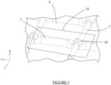
- repair sheet 32 of membrane 6 is placed, visible at the figure 7 , covering the replacement portions 27. It is then understood that the repair sheet 32 has dimensions along the longitudinal direction L and transverse direction T of the membrane 6 substantially identical to the dimensions along these same directions, of the portion P removed during the first step.
- the repair sheet 32 can then be welded to the rest of the membrane 6 in order to restore its watertightness.
- the sleeve 28 is inserted into the cavity 18 of an adjacent reinforcement 33 to the cut reinforcement 12, i.e. the one subject to the repair method.
- Adjacent reinforcement 33 is understood to mean the reinforcement arranged next to the cut reinforcement 12 and aligned along the direction of elongation of the reinforcement 12.
- the adjacent reinforcement 33 is also distinguished in that it is not intended to be replaced. by the replacement portions 27, the latter being used exclusively for the single reinforcement 12 which is the subject of the repair.
- the cut reinforcement 12 and the adjacent reinforcement 33 are distinct but form part of the same first series of reinforcements 15 or second series of reinforcements 16, and are directly connected to each other by one of the connecting pieces 21 of said series of reinforcements 15, 16.
- the sleeve 28 is then inserted into the cavity 18 of the adjacent reinforcement 33 by a translational movement following the main elongation direction of the reinforcement 12, in a second insertion direction I2 going from the first end 29 towards the second end 30, such that the first end 29 emerges outside a volume defined by the cavity 18 of the adjacent reinforcement 33, opposite the first reinforcement portion 24.
- the locking means 31 of the sleeve 28 can be arranged at its first end 29.
- the locking means 31 temporarily prevents the movement of the sleeve 28 following the translational movement previously described in the second insertion direction I2.
- the locking means 31 can then be here, the screw or the Teflon washer.
- Another step of the method according to this second embodiment consists as for the first embodiment, in substituting the first reinforcement portion 24, the second reinforcement portion 25 and the third reinforcement portion 26 by the replacement portions 27, and in such a way that the three replacement portions 27 are aligned according to the main elongation direction of the reinforcement 12 as is visible in the figure. figure 10 .
- the locking means 31 is removed from the sleeve 28 positioned at its first end 29 and said sleeve 28 is translated in the main elongation direction of the reinforcement 12, following the first insertion direction I1 so that it is inserted at least in the cavities 18 of two replacement portions 27.
- the second end 30 can remain outside the cavity 18 of one of the replacement portions 27 located in with regard to the adjacent reinforcement 33, such that the locking means 31 of the sleeve 28 is arranged on said second end 30 of the sleeve 28.
- the translational movement of the sleeve 28 is definitively blocked in the first direction of insertion I1 and in the second direction of insertion I2, the locking means 31 forming a stop against the replacement portion 27 and the adjacent reinforcement 33.
- the closure means 34 may take the form of an adhesive strip.
- the closure means 34 may comprise at least one synthetic insert having a shape complementary to the cavity 18 of the adjacent reinforcement 33. The closure means 34 may then be arranged inside the cavity 18 of the adjacent reinforcement 33 or outside the latter. Also, this closure means 34 may be force-assembled around the adjacent reinforcement 33 or in the cavity 18 of said adjacent reinforcement 33, the closure means 34 then being able to be crenellated to ensure mechanical holding of said closure means 34 on or in the adjacent reinforcement 33.
- the closing device 34 can be put in place prior to the final blocking of the sleeve 28 in the cavities 18 of the replacement portions 27 by the blocking means 31.
- the repair sheet 32 of the membrane 6, visible in the figure is arranged. figure 7 , covering the replacement portions 27.
- the repair sheet 32 then has identical structural characteristics as in the first embodiment of the invention.
Landscapes
- Engineering & Computer Science (AREA)
- Mechanical Engineering (AREA)
- General Engineering & Computer Science (AREA)
- Chemical & Material Sciences (AREA)
- Combustion & Propulsion (AREA)
- Ocean & Marine Engineering (AREA)
- Filling Or Discharging Of Gas Storage Vessels (AREA)
- Working Measures On Existing Buildindgs (AREA)
Description
- La présente invention se rapporte au domaine des cuves de transport à membrane ondulée, pour le stockage et/ou transport d'un fluide, et en particulier les cuves étanches et thermiquement isolantes pour gaz liquéfié.
- L'invention se rapporte au domaine des cuves étanches et thermiquement isolantes pour le stockage et/ou le transport de liquide à basse température, telles que des cuves pour le transport de Gaz de Pétrole Liquéfié (GPL), présentant par exemple une température comprise entre -50°C et 0°C, ou pour le transport de Gaz Naturel Liquéfié (GNL), à environ -162°C à pression atmosphérique. Ces cuves peuvent être installées à terre ou sur un ouvrage flottant. Dans le cas d'un ouvrage flottant, la cuve peut être destinée au transport de gaz liquéfié ou à recevoir du gaz liquéfié servant de carburant pour la propulsion de l'ouvrage flottant.
- Les cuves étanches et thermiquement isolantes utilisées pour le stockage de ces liquides à basse température sont connues par exemple de la demande
FR3077277 - Un inconvénient d'une telle paroi de cuve réside dans sa réparation et plus particulièrement la réparation d'un renfort inséré ou non dans une des ondes de la membrane. En effet, les éléments de la paroi de cuve étant superposés et imbriqués les uns sur les autres, l'accès à chacun des éléments de ladite paroi de cuve nécessite habituellement un démontage au moins d'une partie de la paroi de cuve.
- L'invention a donc pour but de palier à cet inconvénient en proposant un procédé de réparation optimisé, ne nécessitant pas un démontage trop important de la paroi de cuve.
- L'invention a donc pour objet un procédé de réparation d'une paroi de cuve de transport et/ou de stockage de gaz naturel liquéfié, la paroi de cuve comprenant au moins une membrane et une pluralité de renforts, la membrane comprend une pluralité d'ondes dans au moins une desquelles est disposé au moins un renfort, le renfort s'étend dans une direction d'allongement principale et comprend au moins une paroi externe qui délimite une cavité du renfort, procédé de réparation au cours duquel, à au moins une étape, on découpe le renfort suivant une direction sécante à sa direction d'allongement principale de telle sorte à former au moins une première portion de renfort et une deuxième portion de renfort séparables de la paroi de cuve, à une autre étape, on substitue la première portion de renfort et la deuxième portion de renfort par au moins deux portions de remplacement et à une autre étape, on insert un manchon dans la cavité des au moins deux portions de remplacement.
- La cuve peut notamment être la cuve d'un navire de transport de gaz naturel liquéfié et ledit navire peut alors comporter plusieurs cuves pour son stockage et/ou son transport.
- La paroi de cuve comprend alors au moins un massif isolant qui assure l'isolation thermique de la cuve nécessaire pour le transport de gaz naturel liquide et peut notamment comprendre au moins une couche d'isolation. La membrane comprend la pluralité d'ondes réparties sur sa surface. Une telle configuration de la membrane lui procure une plus grande résistance aux contraintes générées sur la cuve, notamment la rétractation thermique lors de la mise à froid de la cuve, la pression hydrostatique due au chargement de la cargaison liquide, ainsi que la pression dynamique due au mouvement de la cargaison, notamment en raison de la houle. Les ondes sur la membrane lui permettent alors de se déformer pour palier à ces contraintes.
- De manière plus précise, la pluralité d'ondes de la membrane est agencée en premières séries d'ondes et deuxièmes séries d'ondes, perpendiculaires l'une de l'autre et dont le croisement forme des noeuds. La pluralité de renforts de la paroi de cuve est alors agencée en premières séries de renforts et deuxièmes séries de renforts, qui s'étendent perpendiculairement l'une de l'autre et respectivement dans les premières séries d'ondes et deuxièmes séries d'ondes. Des pièces de liaison en forme de croix sont alors disposées entre chacun des renforts des premières séries de renforts et deuxièmes séries de renforts, et plus précisément sous les noeuds de la membrane. On comprend alors que les pièces de liaison en croix agencées sous les noeuds ont pour fonction de relier les renforts des premières séries de renforts et deuxièmes séries de renforts entre eux et s'étendent ainsi dans la partie basse des cavités de chacun des renforts.
- L'invention vise à découper un renfort de la paroi de cuve, par exemple endommagé, afin de former au moins deux portions de renfort réparties en la première portion de renfort et la deuxième portion de renfort. Les portions de renfort sont alors séparables, en ce sens qu'elles sont ôtées de la paroi de cuve. Le manchon enfilé dans la cavité des portions de remplacement permet d'aligner lesdites portions de remplacement selon la direction d'allongement principale du renfort. Le manchon se positionne plus particulièrement dans la partie haute de la cavité des portions de remplacement et forme un lien mécanique entre les deux portions de remplacement. On comprend alors que les portions de remplacement utilisées durant le procédé ont pour objectif de remplacer un même et unique renfort endommagé, c'est-à-dire un renfort unitaire avant sa découpe. L'invention trouve une application avantageuse en ce qu'elle permet de réparer au moins un des renforts de la paroi de cuve sans nécessiter de démontage de celle-ci. De manière alternative, l'invention trouve une application avantageuse en ce qu'elle permet la réparation d'au moins un des renforts lors du montage de la paroi de cuve. Les caractéristiques listées ci-dessous relative à un unique renfort s'appliquent mutatismutandis à la pluralité de renforts qui compose la paroi de cuve.
- Selon le procédé de réparation de la paroi de cuve, la pluralité de renforts comprend un renfort adjacent au renfort découpé, le renfort adjacent étant aligné le long de la direction d'allongement principale, procédé au cours duquel on enfile le manchon dans le renfort adjacent préalablement au positionnement des portions de remplacement.
- La pluralité de renforts de la paroi de cuve est organisée en première série de renforts et deuxième série de renforts. Ainsi, on entend par renfort adjacent, celui qui est disposé à côté du renfort découpé dans une même première série de renforts ou dans une même deuxième série de renforts. Le renfort adjacent présente donc les mêmes caractéristiques structurelles que la pluralité de renforts et le manchon est alors inséré dans la cavité dudit renfort adjacent. On comprend également que le renfort adjacent est distinct du renfort endommagé et qu'ainsi, ledit renfort adjacent n'est pas destiné à être remplacé par les portions de remplacement.
- Selon le procédé de réparation de la paroi de cuve, on bloque le manchon dans le renfort adjacent.
- De manière plus précise, on bloque temporairement le manchon dans le renfort adjacent avant la mise en oeuvre des étapes ultérieures du procédé de réparation. Ce blocage du manchon dans le renfort adjacent est avantageux en ce qu'il maintien les éléments entre eux et ainsi facile les opérations de réparations de la paroi de cuve. Le blocage du manchon dans le renfort adjacent peut être mis en oeuvre par un moyen de blocage du manchon prenant la forme d'une vis ou encore d'une rondelle, par exemple en téflon.
- Selon le procédé de réparation de la paroi de cuve, on insère le manchon dans la cavité des portions de remplacement postérieurement au positionnement de ces portions de remplacement sur la paroi de cuve.
- Selon une alternative du procédé de réparation de la paroi de cuve, on translate le manchon suivant la direction d'allongement principale du renfort, depuis le renfort adjacent jusque dans les cavités des portions de remplacement.
- Selon le procédé de réparation de la paroi de cuve, on bloque le manchon dans les cavités des portions de remplacement.
- De manière plus précise, on bloque de manière définitive le manchon dans les cavités des portions de remplacement. Le blocage du manchon dans les cavités des portions de remplacement s'effectue par le moyen de blocage pouvant être une vis ou une rondelle, par exemple en téflon. De manière alternative, le blocage du manchon dans les cavités des portions de remplacement peut être mis en oeuvre en sertissant le manchon par déformation d'une extrémité d'une des portions de remplacement. Toujours de manière alternative, le blocage du manchon dans les cavités d'une des portions de remplacement peut s'effectuer en formant une butée sur l'une des portions de remplacement par apport d'un matériau métallique extérieur, via une opération de soudage.
- Selon le procédé de réparation de la paroi de cuve, on ferme une cavité du renfort adjacent, pour empêcher le manchon de translater dans celle-ci.
- Dit autrement, on obture en partie la cavité du renfort adjacent au niveau de son extrémité en regard du renfort découpé, cette opération pouvant être mise en oeuvre préalablement au blocage définitif du manchon dans les cavités des portions de remplacement. A cette fin, un dispositif de fermeture pouvant prendre la forme par exemple d'un adhésif peut être disposé de telle sorte qu'il ferme au moins partiellement la cavité du renfort selon les conditions évoquées précédemment.
- Selon le procédé de réparation de la paroi de cuve, préalablement à l'étape de découpe du renfort, on retire une portion de membrane positionnée en regard du renfort.
- Dit autrement, on met à nu le renfort faisant l'objet de la mise en oeuvre du procédé de réparation de la paroi de cuve, cette étape étant nécessaire à la mise en oeuvre des étapes ultérieures dudit procédé. Le retrait de la portion de la membrane peut être effectué par exemple par un découpage mécanique ou laser de ladite membrane.
- Selon le procédé de réparation de la paroi de cuve, on solidarise une tôle de réparation de la membrane en regard du renfort.
- Dit autrement, l'étape finale du procédé de réparation de la paroi de cuve consiste en la mise en place de la tôle de réparation de la membrane en regard du au moins un renfort ayant fait l'objet de la mise en oeuvre du procédé de réparation. On comprend alors que la solidarisation de la tôle de réparation de la membrane s'effectue postérieurement à la mise en place des portions de remplacement sur la paroi de cuve. Dit encore autrement, on place la tôle de réparation en substitution de la portion de la membrane ayant été préalablement retirée lors du procédé de réparation.
- Selon un exemple ne faisant pas partie de l'invention il peut y avoir un kit de réparation d'une paroi de cuve de transport et/ou de stockage de gaz naturel liquéfié, comprenant au moins deux portions de remplacement destinées à remplacer au moins un renfort de la paroi de cuve et au moins un manchon destiné à relier mécaniquement les deux portions de remplacement. Le kit de réparation peut également comprendre une tôle de réparation permettant de recouvrir les portions de remplacement.
- Le kit de réparation participe à la mise en oeuvre du procédé de réparation de la paroi de cuve. On comprend ainsi que les deux portions de remplacement du kit de réparation sont destinées à remplacer toutes deux tout ou partie d'un seul et même renfort endommagé de la paroi de cuve. Dit autrement, le kit de remplacement est utilisé pour le remplacement d'un seul et unique renfort de la paroi de cuve.
- Selon un aspect de ce kit, le manchon est configuré pour se loger dans une partie haute d'une cavité des portions de remplacement, la partie haute de la cavité étant de forme triangulaire.
- Selon un autre aspect, le manchon est de section circulaire.
- Selon une caractéristique, le kit de réparation comprend au moins un moyen de blocage du manchon par rapport aux portions de remplacement.
- Selon une caractéristique, le kit de réparation comprend au moins un dispositif de fermeture configuré pour obturer la cavité d'un renfort adjacent à l'une des portions de remplacement.
- De manière plus précise, le renfort adjacent est aligné dans la direction d'allongement principale du renfort faisant l'objet du procédé de réparation, c'est-à-dire le renfort découpé. Le renfort découpé comprend alors la portion de remplacement.
- L'exemple ne faisant pas partie de l'invention peut également porter sur une cuve de transport et/ou de stockage de gaz naturel liquéfié pour un navire, comprenant une paroi de cuve et au moins un kit de réparation selon l'une quelconque des caractéristiques précédentes, dans laquelle les portions de remplacement sont rendues solidaires de la paroi de cuve par le manchon, les portions de remplacement étant couvertes par au moins une tôle de réparation.
- D'autres caractéristiques, détails et avantages de l'invention ressortiront plus clairement à la lecture de la description qui suit d'une part, et de plusieurs exemples de réalisation donnés à titre indicatif et non limitatif en référence aux dessins schématiques annexés d'autre part, sur lesquels :
- [
Fig. 1 ] est une vue de côté en perspective d'un navire de transport de gaz liquide avec quatre cuves comprenant l'invention ; - [
Fig.2 ] est une vue rapprochée d'une paroi de cuve montrant un massif isolant, une pluralité de renforts ainsi qu'une partie de la membrane ; - [
Fig.3 ] est une vue rapprochée d'un des renforts de la paroi de cuve découpé en une première portion de renfort, une deuxième portion de renfort et une troisième portion de renfort ; - [
Fig.4 ] est une vue rapprochée du renfort de lafigure 3 comprenant trois portions de remplacement ; - [
Fig.5 ] est une vue en perspective d'un manchon selon l'invention ; - [
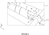
Fig.6 ] est une vue rapprochée du renfort de lafigure 4 dans lequel est inséré le manchon de lafigure 5 ; - [
Fig.7 ] est une vue rapprochée d'une tôle de réparation disposée sur le renfort de lafigure 6 ; - [
Fig.8 ] est une vue rapprochée du renfort de lafigure 3 où a été retiré la première portion de renfort, la deuxième portion de renfort et la troisième portion de renfort et où est visible un renfort adjacent dans lequel on enfile le manchon de lafigure 5 selon un deuxième mode de réalisation de l'invention ; - [
Fig.9 ] est une vue rapprochée du renfort adjacent de lafigure 8 dans lequel a été inséré le manchon de lafigure 5 et sur lequel est visible un moyen de blocage. - [
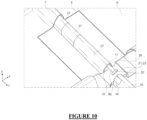
Fig. 10 ] est une vue rapprochée du renfort de lafigure 8 dans lequel ont été intégrées les portions de remplacement, et au sein desquels on a translaté le manchon préalablement inséré dans le renfort adjacent de lafigure 7 . - Les caractéristiques, variantes et les différentes formes de réalisation de l'invention peuvent être associées les unes avec les autres, selon diverses combinaisons, dans la mesure où elles ne sont pas incompatibles ou exclusives les unes aux autres. On pourra notamment imaginer des variantes de l'invention ne comprenant qu'une sélection de caractéristiques décrites par la suite de manière isolée des autres caractéristiques décrites, si cette sélection de caractéristiques est suffisante pour conférer un avantage technique ou pour différencier l'invention par rapport à l'état de la technique antérieur.
- Dans la suite de la description, les dénominations longitudinales ou transversales, se réfèrent à l'orientation de la membrane selon l'invention. Une direction longitudinale L correspond à l'axe de la membrane dans lequel elle s'étend majoritairement, alors que les orientations transversales correspondent à des droites concourantes, c'est-à-dire qui croisent la direction longitudinale, notamment perpendiculaires à la direction longitudinale L de la membrane, pour ce qui concerne la direction transversale T. L'une des directions, illustrée par la flèche référencée V, correspond à une épaisseur de la membrane.
- Les directions évoquées ci-dessus sont visibles dans un repère orthonormé LVT représenté sur les figures.
- Sur la
figure 1 est représenté un navire 1, par exemple un méthanier, qui comporte quatre cuves 2 pour le stockage de gaz à l'état liquide, notamment du gaz naturel liquide. Les cuves 2 sont séparées les unes des autres par des doubles cloisons transversales 3, autrement appelées « cofferdam ». Chacune des cuves 2 est formée d'une paroi de cuve 4 comprenant entre autres un massif isolant 5, visible sur lafigure 2 , formant en partie l'isolation thermique de la paroi de cuve 4, et d'au moins une membrane 6 destinée à être au contact de la cargaison liquide et ancrée sur le massif isolant 5. - La membrane 6, visible à la
figure 2 , est une plaque d'un matériaux anti-corrosion, notamment de l'inox d'épaisseur, par exemple comprise entre 0.5 mm et 1.5 mm, avantageusement 1.2 mm, mesurée dans la direction verticale V de la membrane 6. La membrane peut également comprendre une longueur comprise de 680 mm et 3060 mm, mesurée dans la direction longitudinale L de la membrane 6. Enfin, la membrane 6 peut comprendre une largeur comprise entre de 680 mm et 1030 mm, mesurée dans la direction transversale T de la membrane 6. - La membrane 6 comporte une pluralité d'ondes 7 réparties en une pluralité de premières séries d'ondes 8 parallèles entre elles et s'étendant suivant la direction longitudinale L de la membrane et une pluralité de deuxièmes séries d'ondes 9 parallèles entre elles et s'étendant suivant la direction transversale T de la membrane 6.
- Les premières séries d'ondes 8 et les deuxièmes séries d'ondes 9 s'étendent majoritairement le long de directions qui sont perpendiculaires entres elles, et forment à leur croisement des noeuds 10. Les noeuds 10 émergent verticalement d'un plan AB dans lequel s'inscrit la membrane 6. On entend par onde 7 une déformation de la surface de la membrane 6 dans la direction verticale V.
- La membrane 6 comprend également des portions planes 11 de la forme d'un quadrilatère, dont les deux cotés qui s'étendent suivant la direction longitudinale L de la membrane 6 sont délimités par deux premières séries d'ondes 8, et les deux cotés qui s'étendent suivant la direction transversale T de la membrane 6 sont délimités par deux deuxièmes séries d'ondes 9. L'ensemble des portions planes 11 définit alors la surface non déformée de la membrane 6 s'étendant suivant le plan AB de la membrane 6 et venant au contact du massif isolant 5 de la paroi de cuve 4, lorsque la membrane est montée contre le massif isolant 5.
- La
figure 2 met également en évidence la présence de renforts 12, répartis en premiers renforts 13 et en deuxièmes renforts 14. Dans la suite de la description détaillée, on regroupera les premiers renforts 13 et les deuxièmes renforts 14 sous le terme de renfort 12, lorsque les caractéristiques évoquaient s'appliquent à la fois aux premiers renforts 13 et aux deuxièmes renforts 14. L'invention n'est néanmoins pas limitée à une pluralité de renforts 12 et s'applique dès qu'il est nécessaire de mettre en oeuvre le procédé de réparation sur au moins un renfort 12 de la paroi de cuve 4. - Les premiers renforts 13 sont alignés pour former au moins une première série de renforts 15 s'étendant suivant la direction longitudinale L de la membrane 6. Les deuxièmes renforts 14 sont alignés pour former au moins une deuxième série de renforts 16 s'étendant dans la direction transversale T de la membrane 6. La première série de renforts 15 et la deuxième série de renforts 16 sont donc sécantes, notamment perpendiculairement.
- Les premiers renforts 13 sont disposés dans la première série d'ondes 8 de la membrane 6. On comprend que les premiers renforts 13 sont positionnés de manière à être imbriqués dans la déformation de l'onde 7, la forme des premiers renforts 13 étant complémentaire de la forme des ondes de la première série d'ondes 8 de la membrane 6.
- Les deuxièmes renforts 14 sont disposés dans la deuxième série d'ondes 9 de la membrane 6. On comprend alors que les deuxièmes renforts 14 sont positionnés de manière à être imbriqués dans la déformation de l'onde 7, la forme des deuxièmes renforts 14 étant complémentaire de la forme des ondes 7 de la deuxième série d'ondes 9 de la membrane 6.
- On comprend également que l'intersection entre la première série de renforts 15 et la deuxième série de renforts 16 est positionnée sous un noeud 10 de la membrane 6.
- Les renforts 12 comprennent une paroi externe 17 qui délimite une cavité 18. On comprend alors de ce qui précède que la paroi externe 17 procure une forme aux renforts 12 afin que ceux-ci soient aptes à être disposés dans les ondes 7 de la membrane 6 selon les caractéristiques précédentes.
- Des pièces de liaison 21, sont disposées dans les premiers renforts 13 et dans les deuxièmes renforts 14 de la membrane 6, de telle sorte qu'ils soient reliés entre eux sous les séries d'ondes 8, 9 de la membrane 6. Les pièces de liaison 21 sont ainsi placées au droit d'un noeud 10 de la membrane 6 et insérée dans chacune des cavités 18 des renforts 12. Les pièces de liaison 21 peuvent être, par exemple et de manière non limitative, sous forme de croix 22. On comprend alors que l'ensemble des renforts 12 composant les premières séries de renforts 15 et les deuxièmes séries de renforts 16 forment un ensemble solidaire disposé entre la membrane 6 et le massif isolant 5 de la paroi de cuve 4 tel que cela a été décrit précédemment.
- Un procédé de réparation de la paroi de cuve 4 va maintenant être décrit en rapport avec les
figures 3 à 10 . Plus particulièrement, le procédé de réparation permet la mise en oeuvre d'une réparation simplifiée de la paroi de cuve 4, par exemple la réparation d'au moins un des renforts 12 de ladite paroi de cuve 4. Dans la suite de la description, on comprendra que le procédé peut être mis en oeuvre sur au moins un des renforts 12 de la première série de renforts 15 et/ou sur au moins un des renforts 12 de la deuxième série de renforts 16. Ainsi on définit et regroupe sous le terme de direction d'allongement principale du renfort, la direction longitudinale L de la membrane 6 pour les premiers renforts 13 et la direction transversale T de la membrane 6 pour les deuxièmes renforts 14. - Une première étape du procédé de réparation de la cuve 2 consiste à ménager un accès au renfort 12 faisant l'objet du procédé de réparation, à l'opérateur. A cette fin, on retire une portion P, visible sur la
figure 2 , de la membrane 6 se trouvant en regard dudit renfort 12, par exemple au moyen d'un découpage laser ou mécanique. - Il convient de considérer que de manière alternative et non illustré, le procédé de réparation peut être mis en oeuvre lors du montage de la paroi de cuve, avant que la membrane ne soit disposée en recouvrement des renforts qui composent la paroi de cuve, et qu'ainsi la première étape de retrait de la portion de membrane n'est pas mise en oeuvre.
- Une fois le renfort 12 mis à nu, une deuxième étape du procédé de réparation consiste au découpage du renfort 12 suivant une direction sécante de sa direction d'allongement principale, de telle sorte qu'on forme des portions de renfort 23, et plus précisément au moins une première portion de renfort 24 et une deuxième portion de renfort 25. Dans l'exemple illustré, on forme également une troisième portion de renfort 26, mais on comprend que le procédé peut s'appliquer à plus ou moins de portions de renfort 23. On comprend également que lors de la deuxième étape du procédé, on découpe un unique et même renfort 12 de la paroi de cuve 4, de telle sorte que ce même renfort 12 devient la première portion de renfort 24, la deuxième portion de renfort 25 et la troisième portion de renfort 26 après découpage du renfort 12.
- On obtient ainsi, selon l'exemple illustré à la
figure 3 , la première portion de renfort 24, la deuxième portion de renfort 25 et la troisième portion de renfort 26 qui sont destinées à être séparées de la paroi de cuve 4. On entend par séparable de la paroi de cuve 4 que les portions de renfort 24, 25, 26 sont destinées à être retirées définitivement de la paroi de cuve 4 afin d'être remplacées par des portions de remplacement 27. - De manière alternative et non illustré, au moins une des portions de renfort 24, 25, 26 peut être amovible, en ce sens qu'elle peut être réinstallée sur la paroi de cuve à la suite de la substitution d'au moins une des portions de renforts 24, 25, 26 par au moins une portion de remplacement 27.
- Selon un premier mode de réalisation du procédé visible à la
figure 4 , à l'issue du retrait de la première portion de renfort 24, de la deuxième portion de renfort 25 et de la troisième portion de renfort 26, on dispose les portions de remplacement 27, de telle sorte qu'elles se substituent auxdites première portion de renfort 24, deuxième portion de renfort 25 et troisième portion de renfort 26. On comprend alors que les portions de remplacement 27 sont toutes trois alignées selon la direction d'allongement du renfort 12. On comprend également que les portions de remplacement 27 ont pour fonction de remplacer un même et unique renfort 12 de la paroi de cuve 4. - Par la suite, à une étape additionnelle, on enfile un manchon 28, visible à la
figure 5 , au moins dans deux cavités 18 de deux portions de remplacement 27. Dans l'exemple illustré à lafigure 6 , le manchon 28 est enfilé dans les trois cavités 18 des trois portions de remplacement 27. - Le manchon 28 présente une forme allongée ainsi qu'une première extrémité 29 et une deuxième extrémité 30, opposées l'une de l'autre de part et d'autre du manchon 28. L'insertion du manchon 28 telle que précédemment évoquée, s'effectue majoritairement par un mouvement translatoire, suivant la direction d'allongement principale du renfort 12, depuis la deuxième extrémité 30 vers la première extrémité 29, que l'on qualifie alors de premier sens d'insertion I1. Le manchon 28 a alors pour fonction de bloquer au moins les mouvements entre les portions de remplacement 27 suivant des directions perpendiculaires à la direction d'allongement dudit renfort 12.
- Toujours dans ce premier mode de réalisation, on peut prévoir qu'on insère le manchon 28 selon les caractéristiques d'insertion précédentes, tout en laissant subsister la deuxième extrémité 30 dudit manchon 28 en dehors d'un volume définit par la cavité 18 d'une des portions de remplacement 27 située à une extrémité de l'alignement des portions de remplacement 27. De la sorte on permet la mise en place d'un moyen de blocage 31 du manchon 28 au niveau de sa deuxième extrémité 30. Le moyen de blocage 31 peut être par exemple et de manière non limitative une vis ou une rondelle en téflon. Le moyen de blocage 31 a pour fonction de bloquer le mouvement du manchon 28, ici de manière définitive, suivant le mouvement translatoire précédemment décrit, au moins dans le premier sens d'insertion I1 en formant une butée contre la portion de remplacement 27. De manière alternative, le moyen de blocage 31 peut être une déformation d'une des portions de remplacement 27 de telle sorte qu'elle empêche les mouvements du manchon 28, ou encore une adjonction d'un matériau métallique sur une des portions de remplacement 27 afin de former un moyen de butée et de telle sorte que le manchon 28 soit laissé libre.
- Par la suite, on dispose une tôle de réparation 32 de membrane 6, visible à la
figure 7 , en recouvrement des portions de remplacement 27. On comprend alors que la tôle de réparation 32 présente des dimensions suivant la direction longitudinale L et transversale T de la membrane 6 sensiblement identiques aux dimensions suivant ces mêmes directions, de la portion P retirée lors de la première étape. - La tôle de réparation 32 peut alors être soudée au reste de la membrane 6 afin de rétablir l'étanchéité de celle-ci.
- Selon un deuxième mode de réalisation de l'invention, à l'issue du retrait de la première portion de renfort 24, de la deuxième portion de renfort 25 et de la troisième portion de renfort 26 de la paroi de cuve, à une étape additionnelle, on enfile le manchon 28 dans la cavité 18 d'un renfort adjacent 33 au renfort 12 découpé, c'est-à-dire celui faisant l'objet du procédé de réparation. On entend par renfort adjacent 33 le renfort disposé à côté du renfort 12 découpé et aligné le long de la direction d'allongement du renfort 12. Le renfort adjacent 33 se distingue également en ce qu'il n'est pas destiné à être remplacé par les portions de remplacement 27, ces dernières étant utilisées exclusivement pour l'unique renfort 12 objet de la réparation. Dit autrement, le renfort 12 découpé et le renfort adjacent 33 sont distincts mais font partie d'une même première série de renforts 15 ou deuxième série de renforts 16, et sont directement reliés l'un à l'autre par une des pièces de liaison 21 de ladite série de renforts 15, 16.
- Le manchon 28 est alors inséré dans la cavité 18 du renfort adjacent 33 par un mouvement de translation suivant la direction d'allongement principale du renfort 12, dans un deuxième sens d'insertion I2 allant de la première extrémité 29 vers la deuxième extrémité 30, de telle sorte que la première extrémité 29 émerge en dehors d'un volume définit par la cavité 18 du renfort adjacent 33, en regard de la première portion de renfort 24.
- Selon un exemple de l'invention, visible à la
figure 9 , on peut disposer le moyen de blocage 31 du manchon 28 au niveau de sa première extrémité 29. Dans cette configuration, le moyen de blocage 31 empêche temporairement le mouvement du manchon 28 suivant le mouvement translatoire précédemment décrit dans le deuxième sens d'insertion I2. Le moyen de blocage 31 peut alors être ici, la vis ou la rondelle en téflon. - Une autre étape du procédé selon ce deuxième mode de réalisation, consiste comme pour le premier mode de réalisation, à substituer la première portion de renfort 24, la deuxième portion de renfort 25 et la troisième portion de renfort 26 par les portions de remplacement 27, et de telle sorte que les trois portions de remplacement 27 soient alignées suivant la direction d'allongement principale du renfort 12 comme cela est visible à la
figure 10 . - Comme illustré à la
figure 10 , à la suite de cette étape, on retire le moyen de blocage 31 du manchon 28 positionné à sa première extrémité 29 et on translate ledit manchon 28 selon la direction d'allongement principale du renfort 12, suivant le premier sens d'insertion I1 de telle sorte qu'il s'insère au moins dans les cavités 18 de deux portions de remplacement 27. Selon un exemple de l'invention, la deuxième extrémité 30 peut subsister en dehors de la cavité 18 d'une des portions de remplacement 27 située en regard du renfort adjacent 33, de telle sorte qu'on dispose le moyen de blocage 31 du manchon 28 sur ladite deuxième extrémité 30 du manchon 28. Ainsi, on bloque définitivement le mouvement translatoire du manchon 28 selon le premier sens d'insertion I1 et selon le deuxième sens d'insertion I2, le moyen de blocage 31 formant une butée contre la portion de remplacement 27 et le renfort adjacent 33. - Une étape supplémentaire de ce deuxième mode de réalisation du procédé, peut-être la fermeture de la cavité 18 du renfort adjacent 33 au niveau de son extrémité en regard du renfort 12 découpé, au moyen d'un dispositif de fermeture 34. Dit autrement, on obture l'extrémité de la cavité 18 du renfort adjacent 33 se trouvant en regard de la deuxième extrémité 30 du manchon 28 portant le moyen de blocage 31. De la sorte, on permet le retrait du moyen de blocage 31 de la deuxième extrémité 30 du manchon 28, le dispositif de fermeture 34 empêchant le manchon 28 de translater dans la cavité 18 du renfort adjacent 33 suivant le deuxième sens d'insertion I2.
- Selon un exemple, le moyen de fermeture 34 peut prendre la forme d'une bande adhésive. Selon un autre exemple de l'invention, le moyen de fermeture 34 peut comprendre au moins un insert synthétique présentant une forme complémentaire à la cavité 18 du renfort adjacent 33. Le moyen de fermeture 34 peut alors être disposé à l'intérieur de la cavité 18 du renfort adjacent 33 ou à l'extérieur de ce dernier. Egalement, ce moyen de fermeture 34 peut être assemblé en force autour du renfort adjacent 33 ou dans la cavité 18 dudit renfort adjacent 33, le moyen de fermeture 34 pouvant alors être crénelé pour assurer une tenue mécanique dudit moyen de fermeture 34 sur ou dans le renfort adjacent 33.
- De manière alternative, le dispositif de fermeture 34 peut être mis en place préalablement au blocage définitif du manchon 28 dans les cavités 18 des portions de remplacement 27 par le moyen de blocage 31.
- Enfin et de manière commune au premier mode de réalisation de l'invention, on dispose la tôle de réparation 32 de membrane 6, visible à la
figure 7 , en recouvrement des portions de remplacement 27. La tôle de réparation 32 présente alors des caractéristiques structurelles identiques que dans le premier mode de réalisation de l'invention. - La présente invention ne saurait toutefois se limiter aux moyens et configurations décrits et illustrés ici, et elle s'étend également à tout moyen et configuration équivalents et à toute combinaison techniquement opérante de tels moyens, tant qu'ils restent dans le cadre de l'invention tel que définit par les revendications.
Claims (9)
- Procédé de réparation d'une paroi de cuve (4) de transport et/ou de stockage de gaz naturel liquéfié, la paroi de cuve (4) comprenant au moins une membrane (6) et une pluralité de renforts (12), la membrane (6) comprenant une pluralité d'ondes (7) dans au moins une desquelles est disposé au moins un renfort (12), le renfort (12) s'étendant dans une direction d'allongement principale et comprenant au moins une paroi externe (17) qui délimite une cavité (18) du renfort (12), le procédé de réparation étant caractérisé en ce que, à au moins une étape, on découpe le renfort (12) suivant une direction sécante à sa direction d'allongement principale de telle sorte à former au moins une première portion de renfort (24) et une deuxième portion de renfort (25) séparables de la paroi de cuve (4), à une autre étape, on substitue la première portion de renfort (24) et la deuxième portion de renfort (25) par au moins deux portions de remplacement (27) et à une autre étape, on insère un manchon (28) dans la cavité (18) des au moins deux portions de remplacement (27).
- Procédé de réparation selon la revendication 1, dans lequel la pluralité de renforts (12) comprend un renfort adjacent (33) au renfort (12) découpé, le renfort adjacent (33) étant aligné le long de la direction d'allongement principale, procédé au cours duquel on enfile le manchon (28) dans le renfort adjacent (33) préalablement au positionnement de la portion de remplacement (27).
- Procédé de réparation selon la revendication 2, au cours duquel on bloque le manchon (28) dans le renfort adjacent (33).
- Procédé de réparation selon la revendication 1 ou 3, au cours duquel on insère le manchon (28) dans la cavité (18) des portions de remplacement (27) postérieurement au positionnement de ces portions de remplacement (27) sur la paroi de cuve (4).
- Procédé de réparation selon la revendication précédente, au cours duquel on translate le manchon (28) suivant la direction d'allongement principale du renfort (12), depuis le renfort adjacent (33) jusque dans les cavités (18) des portions de remplacement (27).
- Procédé de réparation selon la revendication précédente, au cours duquel on bloque le manchon (28) dans les cavités (18) des portions de remplacement (27).
- Procédé de réparation selon la revendication 2 et 6, au cours duquel on ferme une cavité (18) du renfort adjacent (33), pour empêcher le manchon (28) de translater dans celle-ci.
- Procédé de réparation selon l'une quelconque des revendications précédentes, au cours duquel préalablement à l'étape de découpe du renfort (12), on retire une portion (P) de membrane (6) positionnée en regard du renfort (12).
- Procédé de réparation selon la revendication 7, au cours duquel on solidarise une tôle de réparation (32) de la membrane (6) en regard du renfort (12).
Applications Claiming Priority (2)
| Application Number | Priority Date | Filing Date | Title |
|---|---|---|---|
| FR1910637A FR3101337B1 (fr) | 2019-09-26 | 2019-09-26 | Procédé de réparation d’une paroi de cuve de transport et/ou de stockage de gaz naturel liquéfié. |
| PCT/FR2020/051670 WO2021058917A1 (fr) | 2019-09-26 | 2020-09-25 | Procédé de réparation d'une paroi de cuve de transport et/ou de stockage de gaz naturel liquéfié |
Publications (2)
| Publication Number | Publication Date |
|---|---|
| EP4034800A1 EP4034800A1 (fr) | 2022-08-03 |
| EP4034800B1 true EP4034800B1 (fr) | 2024-11-27 |
Family
ID=69810912
Family Applications (1)
| Application Number | Title | Priority Date | Filing Date |
|---|---|---|---|
| EP20790376.6A Active EP4034800B1 (fr) | 2019-09-26 | 2020-09-25 | Procédé de réparation d'une paroi de cuve de transport et/ou de stockage de gaz naturel liquéfié |
Country Status (7)
| Country | Link |
|---|---|
| EP (1) | EP4034800B1 (fr) |
| JP (1) | JP7592075B2 (fr) |
| KR (1) | KR102884367B1 (fr) |
| CN (1) | CN114502875B (fr) |
| ES (1) | ES3013875T3 (fr) |
| FR (1) | FR3101337B1 (fr) |
| WO (1) | WO2021058917A1 (fr) |
Family Cites Families (9)
| Publication number | Priority date | Publication date | Assignee | Title |
|---|---|---|---|---|
| DE3135602A1 (de) * | 1981-09-09 | 1983-03-24 | Stahlgruber Otto Gruber GmbH & Co, 8000 MÜnchen | "kaltreparatur an einem stahlseilfoerdergurt" |
| JPH0651513B2 (ja) * | 1989-02-23 | 1994-07-06 | 株式会社高田工業所 | タンクのアニュラープレート取り替え方法 |
| FR2968284B1 (fr) | 2010-12-01 | 2013-12-20 | Gaztransp Et Technigaz | Barriere d'etancheite pour une paroi de cuve |
| KR101422551B1 (ko) * | 2013-03-14 | 2014-07-24 | 주식회사 대양계기 | 액화천연가스 운반선의 엘엔쥐화물창의 온도센서 구조체의 수리방법 |
| KR101672221B1 (ko) * | 2014-06-05 | 2016-11-04 | 삼성중공업 주식회사 | 액화가스 화물창 및 이에 사용되는 방벽보강부재 |
| FR3039248B1 (fr) | 2015-07-24 | 2017-08-18 | Gaztransport Et Technigaz | Cuve etanche et thermiquement isolante munie d'une piece de renfort |
| CN105735205A (zh) * | 2016-03-04 | 2016-07-06 | 中国电建集团华东勘测设计研究院有限公司 | 一种混凝土面板水平施工缝错台修复方式 |
| FR3077278B1 (fr) * | 2018-02-01 | 2020-02-07 | Gaztransport Et Technigaz | Paroi etanche a membrane ondulee renforcee |
| JP6503599B1 (ja) * | 2018-09-20 | 2019-04-24 | 三菱重工環境・化学エンジニアリング株式会社 | 分割交換用炉体及び流動床焼却炉の補修方法 |
-
2019
- 2019-09-26 FR FR1910637A patent/FR3101337B1/fr active Active
-
2020
- 2020-09-25 KR KR1020227013456A patent/KR102884367B1/ko active Active
- 2020-09-25 CN CN202080067681.7A patent/CN114502875B/zh active Active
- 2020-09-25 WO PCT/FR2020/051670 patent/WO2021058917A1/fr not_active Ceased
- 2020-09-25 ES ES20790376T patent/ES3013875T3/es active Active
- 2020-09-25 JP JP2022519227A patent/JP7592075B2/ja active Active
- 2020-09-25 EP EP20790376.6A patent/EP4034800B1/fr active Active
Also Published As
| Publication number | Publication date |
|---|---|
| JP2022550346A (ja) | 2022-12-01 |
| KR20220065047A (ko) | 2022-05-19 |
| JP7592075B2 (ja) | 2024-11-29 |
| ES3013875T3 (en) | 2025-04-15 |
| KR102884367B1 (ko) | 2025-11-10 |
| EP4034800A1 (fr) | 2022-08-03 |
| CN114502875B (zh) | 2024-03-12 |
| FR3101337A1 (fr) | 2021-04-02 |
| CN114502875A (zh) | 2022-05-13 |
| FR3101337B1 (fr) | 2021-12-10 |
| WO2021058917A1 (fr) | 2021-04-01 |
Similar Documents
| Publication | Publication Date | Title |
|---|---|---|
| EP3365592B1 (fr) | Cuve comprenant des blocs isolants de coin equipes de fentes de relaxation | |
| EP3942219B1 (fr) | Cuve étanche et thermiquement isolante | |
| FR3073270B1 (fr) | Cuve etanche et thermiquement isolante comportant des dispositifs d'ancrage des panneaux isolants primaires sur des panneaux isolants secondaires | |
| FR3077278A1 (fr) | Paroi etanche a membrane ondulee renforcee | |
| FR3105342A1 (fr) | Barrière thermiquement isolante pour une paroi d’une cuve | |
| WO2020021208A1 (fr) | Cuve etanche et thermiquement isolante | |
| WO2020193683A1 (fr) | Dispositif de maintien de renforts d'onde lors de l'installation d'une paroi de cuve | |
| FR3112588A1 (fr) | Paroi d'une cuve de stockage d'un gaz liquéfiée | |
| FR3109978A1 (fr) | Dôme liquide d’une cuve de stockage pour gaz liquéfié comportant une ouverture munie d’une trappe additionnelle | |
| WO2021144531A1 (fr) | Double trappe d'accès pour une cuve de transport de gaz liquéfié | |
| EP4034800A1 (fr) | Procédé de réparation d'une paroi de cuve de transport et/ou de stockage de gaz naturel liquéfié | |
| WO2021255000A1 (fr) | Dôme liquide d'une cuve de stockage pour gaz liquéfié | |
| WO2019145635A1 (fr) | Cuve etanche et thermiquement isolante | |
| WO2022100975A1 (fr) | Procédé de fabrication d'une barrière thermiquement isolante pour une cuve | |
| FR3077115A1 (fr) | Cuve etanche et thermiquement isolante. | |
| FR3122240A1 (fr) | Dispositif de maintien d’un maillage de renforts d’onde. | |
| WO2023118716A1 (fr) | Cuve comprenant une membrane étanche présentant des traversées | |
| WO2021254999A1 (fr) | Dôme liquide d'une cuve de stockage pour gaz liquéfié | |
| FR3108267A1 (fr) | Outil de poinçonnage et système pour la connexion d’une pluralité de renforts d’onde d’une membrane corruguée d’une cuve étanche et thermiquement isolante | |
| EP4222406A1 (fr) | Procédé d'assemblage et installation de cuve de stockage pour gaz liquéfié | |
| WO2021074413A1 (fr) | Poutre de raccordement pour une cuve etanche et thermiquement isolante de stockage de gaz liquefie | |
| FR3118796A1 (fr) | Installation de stockage pour gaz liquéfié | |
| WO2025133374A1 (fr) | Cuve étanche | |
| FR3157513A1 (fr) | Cuve étanche | |
| WO2022171490A1 (fr) | Dispositif porte-flotteur |
Legal Events
| Date | Code | Title | Description |
|---|---|---|---|
| STAA | Information on the status of an ep patent application or granted ep patent |
Free format text: STATUS: UNKNOWN |
|
| STAA | Information on the status of an ep patent application or granted ep patent |
Free format text: STATUS: THE INTERNATIONAL PUBLICATION HAS BEEN MADE |
|
| PUAI | Public reference made under article 153(3) epc to a published international application that has entered the european phase |
Free format text: ORIGINAL CODE: 0009012 |
|
| STAA | Information on the status of an ep patent application or granted ep patent |
Free format text: STATUS: REQUEST FOR EXAMINATION WAS MADE |
|
| 17P | Request for examination filed |
Effective date: 20220415 |
|
| AK | Designated contracting states |
Kind code of ref document: A1 Designated state(s): AL AT BE BG CH CY CZ DE DK EE ES FI FR GB GR HR HU IE IS IT LI LT LU LV MC MK MT NL NO PL PT RO RS SE SI SK SM TR |
|
| DAV | Request for validation of the european patent (deleted) | ||
| DAX | Request for extension of the european patent (deleted) | ||
| GRAP | Despatch of communication of intention to grant a patent |
Free format text: ORIGINAL CODE: EPIDOSNIGR1 |
|
| STAA | Information on the status of an ep patent application or granted ep patent |
Free format text: STATUS: GRANT OF PATENT IS INTENDED |
|
| INTG | Intention to grant announced |
Effective date: 20240723 |
|
| GRAS | Grant fee paid |
Free format text: ORIGINAL CODE: EPIDOSNIGR3 |
|
| GRAA | (expected) grant |
Free format text: ORIGINAL CODE: 0009210 |
|
| STAA | Information on the status of an ep patent application or granted ep patent |
Free format text: STATUS: THE PATENT HAS BEEN GRANTED |
|
| AK | Designated contracting states |
Kind code of ref document: B1 Designated state(s): AL AT BE BG CH CY CZ DE DK EE ES FI FR GB GR HR HU IE IS IT LI LT LU LV MC MK MT NL NO PL PT RO RS SE SI SK SM TR |
|
| REG | Reference to a national code |
Ref country code: GB Ref legal event code: FG4D Free format text: NOT ENGLISH |
|
| REG | Reference to a national code |
Ref country code: CH Ref legal event code: EP |
|
| REG | Reference to a national code |
Ref country code: IE Ref legal event code: FG4D Free format text: LANGUAGE OF EP DOCUMENT: FRENCH |
|
| REG | Reference to a national code |
Ref country code: DE Ref legal event code: R096 Ref document number: 602020042133 Country of ref document: DE |
|
| REG | Reference to a national code |
Ref country code: LT Ref legal event code: MG9D |
|
| REG | Reference to a national code |
Ref country code: NL Ref legal event code: MP Effective date: 20241127 |
|
| PG25 | Lapsed in a contracting state [announced via postgrant information from national office to epo] |
Ref country code: HR Free format text: LAPSE BECAUSE OF FAILURE TO SUBMIT A TRANSLATION OF THE DESCRIPTION OR TO PAY THE FEE WITHIN THE PRESCRIBED TIME-LIMIT Effective date: 20241127 Ref country code: PT Free format text: LAPSE BECAUSE OF FAILURE TO SUBMIT A TRANSLATION OF THE DESCRIPTION OR TO PAY THE FEE WITHIN THE PRESCRIBED TIME-LIMIT Effective date: 20250327 Ref country code: IS Free format text: LAPSE BECAUSE OF FAILURE TO SUBMIT A TRANSLATION OF THE DESCRIPTION OR TO PAY THE FEE WITHIN THE PRESCRIBED TIME-LIMIT Effective date: 20250327 |
|
| PG25 | Lapsed in a contracting state [announced via postgrant information from national office to epo] |
Ref country code: FI Free format text: LAPSE BECAUSE OF FAILURE TO SUBMIT A TRANSLATION OF THE DESCRIPTION OR TO PAY THE FEE WITHIN THE PRESCRIBED TIME-LIMIT Effective date: 20241127 Ref country code: NL Free format text: LAPSE BECAUSE OF FAILURE TO SUBMIT A TRANSLATION OF THE DESCRIPTION OR TO PAY THE FEE WITHIN THE PRESCRIBED TIME-LIMIT Effective date: 20241127 |
|
| REG | Reference to a national code |
Ref country code: AT Ref legal event code: MK05 Ref document number: 1746019 Country of ref document: AT Kind code of ref document: T Effective date: 20241127 Ref country code: ES Ref legal event code: FG2A Ref document number: 3013875 Country of ref document: ES Kind code of ref document: T3 Effective date: 20250415 |
|
| PG25 | Lapsed in a contracting state [announced via postgrant information from national office to epo] |
Ref country code: BG Free format text: LAPSE BECAUSE OF FAILURE TO SUBMIT A TRANSLATION OF THE DESCRIPTION OR TO PAY THE FEE WITHIN THE PRESCRIBED TIME-LIMIT Effective date: 20241127 |
|
| PG25 | Lapsed in a contracting state [announced via postgrant information from national office to epo] |
Ref country code: LV Free format text: LAPSE BECAUSE OF FAILURE TO SUBMIT A TRANSLATION OF THE DESCRIPTION OR TO PAY THE FEE WITHIN THE PRESCRIBED TIME-LIMIT Effective date: 20241127 Ref country code: GR Free format text: LAPSE BECAUSE OF FAILURE TO SUBMIT A TRANSLATION OF THE DESCRIPTION OR TO PAY THE FEE WITHIN THE PRESCRIBED TIME-LIMIT Effective date: 20250228 Ref country code: AT Free format text: LAPSE BECAUSE OF FAILURE TO SUBMIT A TRANSLATION OF THE DESCRIPTION OR TO PAY THE FEE WITHIN THE PRESCRIBED TIME-LIMIT Effective date: 20241127 |
|
| PG25 | Lapsed in a contracting state [announced via postgrant information from national office to epo] |
Ref country code: PL Free format text: LAPSE BECAUSE OF FAILURE TO SUBMIT A TRANSLATION OF THE DESCRIPTION OR TO PAY THE FEE WITHIN THE PRESCRIBED TIME-LIMIT Effective date: 20241127 |
|
| PG25 | Lapsed in a contracting state [announced via postgrant information from national office to epo] |
Ref country code: RS Free format text: LAPSE BECAUSE OF FAILURE TO SUBMIT A TRANSLATION OF THE DESCRIPTION OR TO PAY THE FEE WITHIN THE PRESCRIBED TIME-LIMIT Effective date: 20250227 |
|
| PG25 | Lapsed in a contracting state [announced via postgrant information from national office to epo] |
Ref country code: SM Free format text: LAPSE BECAUSE OF FAILURE TO SUBMIT A TRANSLATION OF THE DESCRIPTION OR TO PAY THE FEE WITHIN THE PRESCRIBED TIME-LIMIT Effective date: 20241127 |
|
| PG25 | Lapsed in a contracting state [announced via postgrant information from national office to epo] |
Ref country code: DK Free format text: LAPSE BECAUSE OF FAILURE TO SUBMIT A TRANSLATION OF THE DESCRIPTION OR TO PAY THE FEE WITHIN THE PRESCRIBED TIME-LIMIT Effective date: 20241127 |
|
| PGFP | Annual fee paid to national office [announced via postgrant information from national office to epo] |
Ref country code: NO Payment date: 20250626 Year of fee payment: 6 |
|
| PG25 | Lapsed in a contracting state [announced via postgrant information from national office to epo] |
Ref country code: EE Free format text: LAPSE BECAUSE OF FAILURE TO SUBMIT A TRANSLATION OF THE DESCRIPTION OR TO PAY THE FEE WITHIN THE PRESCRIBED TIME-LIMIT Effective date: 20241127 |
|
| PGFP | Annual fee paid to national office [announced via postgrant information from national office to epo] |
Ref country code: FR Payment date: 20250624 Year of fee payment: 6 |
|
| PG25 | Lapsed in a contracting state [announced via postgrant information from national office to epo] |
Ref country code: RO Free format text: LAPSE BECAUSE OF FAILURE TO SUBMIT A TRANSLATION OF THE DESCRIPTION OR TO PAY THE FEE WITHIN THE PRESCRIBED TIME-LIMIT Effective date: 20241127 |
|
| PG25 | Lapsed in a contracting state [announced via postgrant information from national office to epo] |
Ref country code: SK Free format text: LAPSE BECAUSE OF FAILURE TO SUBMIT A TRANSLATION OF THE DESCRIPTION OR TO PAY THE FEE WITHIN THE PRESCRIBED TIME-LIMIT Effective date: 20241127 |
|
| PG25 | Lapsed in a contracting state [announced via postgrant information from national office to epo] |
Ref country code: CZ Free format text: LAPSE BECAUSE OF FAILURE TO SUBMIT A TRANSLATION OF THE DESCRIPTION OR TO PAY THE FEE WITHIN THE PRESCRIBED TIME-LIMIT Effective date: 20241127 |
|
| PG25 | Lapsed in a contracting state [announced via postgrant information from national office to epo] |
Ref country code: IT Free format text: LAPSE BECAUSE OF FAILURE TO SUBMIT A TRANSLATION OF THE DESCRIPTION OR TO PAY THE FEE WITHIN THE PRESCRIBED TIME-LIMIT Effective date: 20241127 |
|
| REG | Reference to a national code |
Ref country code: DE Ref legal event code: R097 Ref document number: 602020042133 Country of ref document: DE |
|
| PG25 | Lapsed in a contracting state [announced via postgrant information from national office to epo] |
Ref country code: SE Free format text: LAPSE BECAUSE OF FAILURE TO SUBMIT A TRANSLATION OF THE DESCRIPTION OR TO PAY THE FEE WITHIN THE PRESCRIBED TIME-LIMIT Effective date: 20241127 |
|
| PLBE | No opposition filed within time limit |
Free format text: ORIGINAL CODE: 0009261 |
|
| STAA | Information on the status of an ep patent application or granted ep patent |
Free format text: STATUS: NO OPPOSITION FILED WITHIN TIME LIMIT |
|
| REG | Reference to a national code |
Ref country code: CH Ref legal event code: L10 Free format text: ST27 STATUS EVENT CODE: U-0-0-L10-L00 (AS PROVIDED BY THE NATIONAL OFFICE) Effective date: 20251008 |
|
| 26N | No opposition filed |
Effective date: 20250828 |
|
| PGFP | Annual fee paid to national office [announced via postgrant information from national office to epo] |
Ref country code: ES Payment date: 20251001 Year of fee payment: 6 |
|
| REG | Reference to a national code |
Ref country code: CH Ref legal event code: H13 Free format text: ST27 STATUS EVENT CODE: U-0-0-H10-H13 (AS PROVIDED BY THE NATIONAL OFFICE) Effective date: 20260504 |