EP4031373B1 - Pressvorrichtung, anlage und verfahren zur herstellung eines bodenelements - Google Patents
Pressvorrichtung, anlage und verfahren zur herstellung eines bodenelements Download PDFInfo
- Publication number
- EP4031373B1 EP4031373B1 EP20865386.5A EP20865386A EP4031373B1 EP 4031373 B1 EP4031373 B1 EP 4031373B1 EP 20865386 A EP20865386 A EP 20865386A EP 4031373 B1 EP4031373 B1 EP 4031373B1
- Authority
- EP
- European Patent Office
- Prior art keywords
- pressing
- layer
- couple
- movable
- positioning device
- Prior art date
- Legal status (The legal status is an assumption and is not a legal conclusion. Google has not performed a legal analysis and makes no representation as to the accuracy of the status listed.)
- Active
Links
Images


Classifications
-
- B—PERFORMING OPERATIONS; TRANSPORTING
- B30—PRESSES
- B30B—PRESSES IN GENERAL
- B30B5/00—Presses characterised by the use of pressing means other than those mentioned in the preceding groups
- B30B5/04—Presses characterised by the use of pressing means other than those mentioned in the preceding groups wherein the pressing means is in the form of an endless band
- B30B5/06—Presses characterised by the use of pressing means other than those mentioned in the preceding groups wherein the pressing means is in the form of an endless band co-operating with another endless band
-
- B—PERFORMING OPERATIONS; TRANSPORTING
- B30—PRESSES
- B30B—PRESSES IN GENERAL
- B30B15/00—Details of, or accessories for, presses; Auxiliary measures in connection with pressing
- B30B15/08—Accessory tools, e.g. knives; Mountings therefor
-
- B—PERFORMING OPERATIONS; TRANSPORTING
- B30—PRESSES
- B30B—PRESSES IN GENERAL
- B30B15/00—Details of, or accessories for, presses; Auxiliary measures in connection with pressing
- B30B15/30—Feeding material to presses
-
- B—PERFORMING OPERATIONS; TRANSPORTING
- B30—PRESSES
- B30B—PRESSES IN GENERAL
- B30B3/00—Presses characterised by the use of rotary pressing members, e.g. rollers, rings, discs
-
- B—PERFORMING OPERATIONS; TRANSPORTING
- B30—PRESSES
- B30B—PRESSES IN GENERAL
- B30B9/00—Presses specially adapted for particular purposes
- B30B9/28—Presses specially adapted for particular purposes for forming shaped articles
-
- B—PERFORMING OPERATIONS; TRANSPORTING
- B32—LAYERED PRODUCTS
- B32B—LAYERED PRODUCTS, i.e. PRODUCTS BUILT-UP OF STRATA OF FLAT OR NON-FLAT, e.g. CELLULAR OR HONEYCOMB, FORM
- B32B38/00—Ancillary operations in connection with laminating processes
- B32B38/18—Handling of layers or the laminate
- B32B38/1825—Handling of layers or the laminate characterised by the control or constructional features of devices for tensioning, stretching or registration
- B32B38/1833—Positioning, e.g. registration or centering
-
- B—PERFORMING OPERATIONS; TRANSPORTING
- B32—LAYERED PRODUCTS
- B32B—LAYERED PRODUCTS, i.e. PRODUCTS BUILT-UP OF STRATA OF FLAT OR NON-FLAT, e.g. CELLULAR OR HONEYCOMB, FORM
- B32B2419/00—Buildings or parts thereof
- B32B2419/04—Tiles for floors or walls
-
- B—PERFORMING OPERATIONS; TRANSPORTING
- B32—LAYERED PRODUCTS
- B32B—LAYERED PRODUCTS, i.e. PRODUCTS BUILT-UP OF STRATA OF FLAT OR NON-FLAT, e.g. CELLULAR OR HONEYCOMB, FORM
- B32B37/00—Methods or apparatus for laminating, e.g. by curing or by ultrasonic bonding
- B32B37/12—Methods or apparatus for laminating, e.g. by curing or by ultrasonic bonding characterised by using adhesives
- B32B37/1284—Application of adhesive
-
- B—PERFORMING OPERATIONS; TRANSPORTING
- B32—LAYERED PRODUCTS
- B32B—LAYERED PRODUCTS, i.e. PRODUCTS BUILT-UP OF STRATA OF FLAT OR NON-FLAT, e.g. CELLULAR OR HONEYCOMB, FORM
- B32B38/00—Ancillary operations in connection with laminating processes
- B32B38/18—Handling of layers or the laminate
- B32B38/1825—Handling of layers or the laminate characterised by the control or constructional features of devices for tensioning, stretching or registration
- B32B38/1833—Positioning, e.g. registration or centering
- B32B38/1841—Positioning, e.g. registration or centering during laying up
-
- E—FIXED CONSTRUCTIONS
- E04—BUILDING
- E04F—FINISHING WORK ON BUILDINGS, e.g. STAIRS, FLOORS
- E04F15/00—Flooring
- E04F15/02—Flooring or floor layers composed of a number of similar elements
- E04F15/02038—Flooring or floor layers composed of a number of similar elements characterised by tongue and groove connections between neighbouring flooring elements
-
- E—FIXED CONSTRUCTIONS
- E04—BUILDING
- E04F—FINISHING WORK ON BUILDINGS, e.g. STAIRS, FLOORS
- E04F15/00—Flooring
- E04F15/02—Flooring or floor layers composed of a number of similar elements
- E04F15/08—Flooring or floor layers composed of a number of similar elements only of stone or stone-like material, e.g. ceramics, concrete; of glass or with a top layer of stone or stone-like material, e.g. ceramics, concrete or glass
- E04F15/082—Flooring or floor layers composed of a number of similar elements only of stone or stone-like material, e.g. ceramics, concrete; of glass or with a top layer of stone or stone-like material, e.g. ceramics, concrete or glass with a top layer of stone or stone-like material, e.g. ceramics, concrete or glass in combination with a lower layer of other material
- E04F15/087—The lower layer being of organic plastic with or without reinforcements or filling materials
-
- E—FIXED CONSTRUCTIONS
- E04—BUILDING
- E04F—FINISHING WORK ON BUILDINGS, e.g. STAIRS, FLOORS
- E04F2201/00—Joining sheets or plates or panels
- E04F2201/01—Joining sheets, plates or panels with edges in abutting relationship
- E04F2201/0153—Joining sheets, plates or panels with edges in abutting relationship by rotating the sheets, plates or panels around an axis which is parallel to the abutting edges, possibly combined with a sliding movement
-
- E—FIXED CONSTRUCTIONS
- E04—BUILDING
- E04F—FINISHING WORK ON BUILDINGS, e.g. STAIRS, FLOORS
- E04F2201/00—Joining sheets or plates or panels
- E04F2201/02—Non-undercut connections, e.g. tongue and groove connections
- E04F2201/023—Non-undercut connections, e.g. tongue and groove connections with a continuous tongue or groove
-
- E—FIXED CONSTRUCTIONS
- E04—BUILDING
- E04F—FINISHING WORK ON BUILDINGS, e.g. STAIRS, FLOORS
- E04F2201/00—Joining sheets or plates or panels
- E04F2201/04—Other details of tongues or grooves
- E04F2201/043—Other details of tongues or grooves with tongues and grooves being formed by projecting or recessed parts of the panel layers
Definitions
- the present invention relates to a pressing equipment for forming a floor element.
- the present invention relates to a pressing equipment for forming a floor element comprising an upper decorative element, e.g. a ceramic tile or a natural stone, and a lower support element, for example a support element comprising a polymeric material like an LVT or SPC board.
- the invention also relates to a plant and a method for manufacturing a floor element.
- US 7,984,600 B2 discloses an equipment and a method for forming a groutless tile comprising a ceramic tile and a supporting substrate.
- the floor element is manufactured by placing a ceramic tile into a mold and then injecting a polymeric substance, forming the substrate, into the mold so that the substrate is formed directly onto the ceramic tile.
- this method is fast and efficient it requires for expensive molds designed on the basis of the specific product to be manufactured, and in particular on the dimension thereof.
- this method is suitable to be used for manufacturing only substrate made with material that can be injection molded.
- the method disclosed in US 7,984,600 is for manufacture floor elements having a substrate comprising coupling elements that must be machined after the injection molding step. Therefore, during the machining step the machining tool can contact the ceramic tile thereby being damaged.
- EP 3 130 464 A1 discloses an equipment and a method for forming a floor element comprising a stone tile and a supporting polymeric substrate.
- the method provides for spreading a granulated thermoplastic material on a belt, pre-compacting the thermoplastic material to form a web shaped soft layer, placing the stone tile on said web shaped soft layer and then hot pressing the stone tile and the web shaped soft layer to form the floor elements.
- the product web shaped material has to be cut in order to separate the floor elements after the hot-pressing step.
- coupling elements are needed these must be manufactured in a separate machining step on the floor element having the stone tile, similarly to the method of US 7,984,600 .
- this method is suitable to be used only for manufacturing substrates starting from thermoplastic granular materials.
- US 2007/051063 A1 discloses a pressing equipment according to the preamble of claim 1.
- the present invention aims in the first place to provide an alternative pressing equipment and method for manufacturing floor tile, which, in accordance with several of its preferred embodiments, is directed to solve one or more of the problems arising in the state of the art.
- the invention provides a pressing equipment for manufacturing a floor element according to claim 1.
- the disclosure provides a pressing equipment for manufacturing a floor element, wherein the floor element comprises an upper decorative layer and a lower support layer, wherein the equipment comprises: a pressing device, a carrier to move the floor element along an advancing direction during pressing and at least a centering element to keep the mutual position between the upper ceramic element and a lower support element during pressing.
- the invention provides a plant for manufacturing a floor element, the plant comprising a pressing equipment for pressing together the upper decorative layer and the lower support layer according to claim 1, the plant further comprises a gluing device configured to provide a glue on a surface of the decorative layer and/or the lower support layer, said gluing device being disposed upstream to said pressing device.
- the upper decorative layer is a ceramic tile.
- the upper decorative layer can be made of different materials, preferably hard and/or brittle material like, for example, glass, natural stone, cement board, mineral board and/or artificial stone, metal.
- the lower support layer may be made in synthetic material like polymeric material, or polymer based composite material.
- the lower support layer can be made of flexible or, preferably, rigid PVC.
- the PVC lower support layer can preferably comprise one or more fillers like particles and/or fibers.
- the support layer can be made of mineral materials, or cement-based material, like fiber cement material.
- a preferred example of mineral material is magnesium oxide.
- a preferred example of cement-based material is Portland cement.
- Mineral boards or cement-based boards can comprise fibers, like cellulose fibers, wood fibers and/or glass fibers.
- the support layer comprises coupling elements configured for forming a mechanical coupling with coupling elements of an adjacent coupling element.
- the coupling elements can comprise a male part, for example a tongue, and a female part, for example a groove.
- said coupling elements are at least partially provided on the edges of said support layer.
- the coupling elements may be at least partially covered with a removable lining, for example a polymeric film. Said lining can prevent glue and/or resin to overflow on the coupling elements during pressing. Said eventual overflow could harm the coupling capability of the final product.
- the linings can be removed, for example peeled out, after manufacturing of the floor element.
- the pressing device is a stationary pressing device.
- stationary pressing device refers to a pressing device where the floor element stands in a fixed pressing position during the pressing operation. In other words, the pressing position is fixed with respect to the supporting structure.
- the pressing elements comprises at least a piston, preferably a plurality of pistons.
- the positioning device and/or the centering device is fixed in a predetermined position with respect to the pressing device and/or the carrier.
- the positioning device and/or the centering device is movable along the advancing direction together with the pressing device and/or the carrier.
- the positioning device may be fixed to the carrier and the centering device may be fixed to the pressing device, preferably to the belt.
- the positioning device may be substantially formed by a containing cavity provided on the pressing device and/or on the carrier, said containing cavity is defined by walls on which said abutment surfaces and/or contact surfaces are provided.
- Said cavity can be provided in form of excavation or impression made in a surface of the carrier and/or of the pressing belt.
- the cavity can be defined by ribs rising from a surface of the carrier and/or of the pressing belt.
- said ribs are made of polymeric material, preferably of a compressible material.
- the positioning device and or the centering device comprise movable element to adjust the distance between the contact surface of a couple and/or the abutment surfaces of a couple respectively.
- said movable elements are at least movable in a direction transversal, preferably substantially perpendicular to the advancing direction of the floor element.
- said contact surfaces and/or said abutment surfaces are substantially parallel to said advancing direction.
- the positioning device and/or the centering device can be independent with respect to the movement of the pressing device and of the carrier, that is to say that the positioning device and/or the centering device does not move along the advancing direction.
- the pressing equipment may further comprise one or more carrier adapted to transport one or more of the layers of the floor element toward the pressing position and/or transport the floor element away from the pressing position.
- the carrier can comprise one or more belt and/or robotic arm provided with gripping means.
- the carrier can be configured to move the layers toward an inlet opening of the supporting structure and/or to transport the floor element away from an outlet opening of the supporting structure.
- said inlet opening and said outlet opening are placed on different sides, for example opposite sides, of the supporting structure.
- the positioning device and the centering device are configured to respectively keep the position of the floor element in the pressing position during the movement along the advancing direction and keep the mutual position between the upper decorative layer and the lower support layer.
- Said cavity can be provided in form of excavation or impression made in a surface of the carrier and/or of the pressing belt.
- the cavity can be defined by ribs rising from a surface of the carrier and/or of the pressing belt.
- Preferably said ribs are made of polymeric material, preferably of a compressible material.
- the glue is preferably a resin, even more preferably a thermosetting resin.
- a resin even more preferably a thermosetting resin.
- the glue may be a bicomponent resin, in this case the gluing device may comprise a mixing element to mix the two components of the resin, and preferably said mixing means may be configured to mix the two components before and/or during the application of the glue.
- the mixing element can be a tube having internal fins. The two components of the glue flow together in the mixing element so that the turbulent flow caused by the fins allow mixing of the components.
- the mixing element is preferably located close to the nozzle of the gluing device (in case of a sprayer) so that the hardening reaction of the components does not harm the gluing device, for example by clogging the nozzle.
- the glue is a bicomponent resin, or more in general a multicomponent resin
- the plant may also comprise a plurality of gluing devices, wherein each of said gluing devices may be configured to apply one or more of said components.
- the gluing device comprises a roller
- it can comprise means to avoid the resin hardening on the gluing device itself.
- said means can comprise a removable film covering said roller. In this way, the film can be easily removed and substituted without the need of long and expensive cleaning cycles.
- the gluing device can be configured to apply the glue to form a uniform layer and/or according to a predetermined pattern. More preferably, the gluing device is configured to apply the glue in such a way to prevent overflow of the resin beyond the edges of the layers of the floor element and/or on the coupling elements.
- the gluing device can be configured to provide the glue at a predetermined distance from said edges.
- the roller can comprise a relief having the shape and/or the dimension of the pattern and/or of the layer of the glue and it is adapted to be pressed on the surface of the layer on which the glue can be provided.
- the resin has a viscosity at 20°C below 1000 cP, preferably below 750 cP, even more preferably, below 500 cP.
- the gluing device can comprise a heating element to heat up the glue, or at least one of its components, before providing the glue on the layer.
- the gluing device can also comprise a pump and/or a valve assembly to control the flow of the glue.
- the plant can further comprise a handling device for stacking the decorative layer on the support layer or vice versa.
- Said handling device can be, for example, a pantograph or an anthropomorphous robot, and be provided with gripping means.
- the handling device is advantageously provided before the pressing equipment, more preferably between the gluing device and the pressing equipment.
- the plant can further comprises one or more cleaning devices configured to clean the edges and/or the coupling elements of the layers in order to remove possible residue of glue that overflew beyond the edges of the layers.
- Said cleaning devices can comprise, for example, brushes configured to brush the edges and/or the coupling elements of the floor element.
- the cleaning devices are placed at least downstream the gluing device, more preferably downstream the pressing equipment, possibly before and after the pressing equipment.
- the plant can comprise an optical reader configured to read a mark or sign provided on the support layer and/or on the decorative layer.
- Said mark or sign can identify one specific edge and/or one specific coupling element of the layers to check if said layer is provided to the pressing equipment with the correct orientation. Identify the correct orientation of the layers, preferably of at least the lower support layer, is useful for correctly adjust the relative position between layers in the pressing equipment.
- the optical reader can be substituted with any equivalent detecting means suitable to detect a mark or sign. Said detecting means can be contactless or with contact.
- the optical reader, or the detecting means can be disposed downstream the pressing equipment, preferably downstream the gluing line.
- the plant comprises a stocking area disposed downstream the pressing equipment where the floor elements pressed in the pressing equipment can rest during ageing and/or curing of the glue.
- the disclosure relates to a method for manufacturing a floor element comprising the step of: providing at least a first layer to a pressing equipment; providing a second layer to the pressing equipment; adjusting the position of the first layer in a pressing position at the pressing equipment; adjusting the position of the second layer relative to the first layer; pressing the first and the second layer together.
- the first and the second layer can comprise any of the features described above in relation to the decorative and the support layer.
- the method may further comprise the step of stacking the first layer above the second layer. said step of stacking is performed upstream the pressing equipment and then the method comprises the step of providing the stacked layers to the pressing equipment.
- the pressing step it is exerted onto the layers a pressure of at least 350 kg/sqm, more preferably at least 370 kg/sqm.
- the pressure is kept for a pressing time of more than 1 second, preferably more than 10 seconds, for example 30 seconds.
- the method may further comprise the step of applying a glue between the layers.
- the method comprises the step of providing the glue on at least one of the layers before said layer is provided to the pressing equipment. More preferably, the step of providing the resin is performed before said step of stacking the layers.
- the glue is preferably provided onto layer in an amount greater than 150 g/sqm, more preferably greater than 200 g/sqm, for example 220 g/sqm.
- the step of providing a glue can comprise the step of spraying and or roller coating the glue on the layer.
- the step of providing the glue can comprise the step of mixing the components of the glue.
- the step of providing the glue can comprise the step of heating the glue or at least one of its components.
- the resin can be provided to forma uniform layer or a predetermined pattern.
- said coating or pattern is disposed at a predetermined distance from the edges of the layers to prevent the overflow of the glue beyond the edges and/or on the coupling element.
- pressing is performed to spread the glue on the layers to form a uniform intermediate layer between the first and second layer. More preferably, the pressing step is performed so that the glue forms an intermediate layer covers at least 80% of the surface of the layers, preferably of the smaller between the layers. Preferably the pressing is performed so that the intermediate layer covers at between 80 and 95 % of the surface of the layer, preferably of the smaller between the layers.
- the method comprises a step of stocking the floor elements for a stocking time in order to allow the resin to at least partially cure before being, packaged, transported and/or used in a floor covering.
- the stocking time is such to allow the resin to be at least 70% cured, preferably 85% cured, more preferably fully cured.
- said stocking time is at least 0.5 h, preferably more than 1 h, for example 2 h.
- the method may further comprise the step of roughing, for example sanding, the surface of the layer adapted to receive the glue.
- step of roughing is performed before said step of providing the glue.
- the method may be performed by the plant as described above and in particular by one or more of the devices and/or equipment described in relation to the plant.
- Figure 1 shows a floor panel 1 comprising an upper decorative layer 2 and a lower support layer 3.
- the floor panel 1 has a rectangular and oblong shape having a longitudinal length L larger than the transversal width W.
- the upper decorative layer 2 has an upper face 4 comprising a décor 5.
- the décor 5 can be provided with a variety of textures, designs and colors.
- the décor 5 simulates a wood pattern comprising wood nerves and flakes.
- the décor 5 is realized by means of digital printing, such as inkjet printing, although screen printing, rotogravure, flexography or off-set printing is not excluded.
- Figure 2 on a larger scale shows a cross section along the line II-II of Figure 1 .
- the decorative layer 2 is substantially constituted by a ceramic tile.
- Said ceramic tile comprises a body 6 made of a ceramic material, for example red body ceramic or porcelain.
- Said ceramic tile of the decorative layer 2 preferably comprises one or more covering layer 7 covering the upper face of the body 6.
- Said covering layer 7 preferably comprises at least a glaze that substantially form the upper face 4 of the upper decorative layer 2.
- the décor 5 is covered by or comprised in said covering layer 7.
- Figure 2 also shows that decorative layer 2 has a thickness T1 comprised between 4 mm and 15 mm, for example 6 mm, preferably greater than 7 mm, for example 8 mm or 10 mm.
- the ceramic tile constitutes the preferred solution for forming the upper decorative layer 2
- the latter can be alternatively formed by natural stone, glass, ceramic glass material, concrete, mineral board or artificial stone.
- the lower support layer 3 is preferably made of a polymeric material, preferably a thermoplastic material like PVC.
- the board is made of a rigid PVC.
- "rigid” means that the board, taken alone, bends under the own weight thereof less than 10 cm per meter and still better less than 5 cm per meter.
- the lower support layer 3 may also comprise a high amount of filler materials, such as chalk, e.g. more than 30 wt% or more than 60%wt of such filler materials. It is also not excluded that the lower support layer 3 may comprises fiber material, like cellulose or wood fiber, or also wood particles material embedded in said polymeric material.
- cement-based board can be alternatively formed by cement-based board, mineral-based board or boards made of other materials like metal.
- Cement can be preferably Portland cement
- cement-based board can comprise fiber cement board, i.e. fiber containing cement boards.
- Mineral can be preferably magnesium oxide or other metals oxides
- mineral-based board can comprise fiber mineral board, i.e. fiber containing mineral boards.
- the lower support layer 3 preferably has a thickness T2 comprised between 2 mm and 7 mm, preferably less than 6 mm, for example about 4 mm.
- Figure 2 also shows that the lower support layer 3 comprises edges 8 provided with coupling elements 9,10 configured to realize a mechanical coupling with coupling elements 9,10 of an adjacent floor element 1.
- the coupling elements 9,10 comprise a male and female parts disposed on opposite edges 8.
- the male and female parts are respectively shaped in form of a tongue 9 and a groove 10 wherein the tongue 9 projects outwardly beyond its respective edge 8 in a horizontal direction X and the groove 10 projects inwardly with respect to the respective edge 8 in said horizontal direction X.
- the lower support layer 3 extends beyond edges 11 of the upper decorative layer 2.
- the lower support layer 3 comprises upper edges 12, at said edges 8, that extend beyond the edges 11 of the upper decorative layer 2 of a distance D1.
- said distance D1 is equal on all the sides of the floor element 1.
- the lower support layer 3 is larger than the upper decorative layer 2.
- the lower support layer 3 extends beyond all the edges 11 of the upper decorative layer 2
- the lower support layer 3 may extend beyond only some of the edges 11 of the upper decorative layer 2 and that the upper decorative layer 2 extends beyond some of the edges 8 of the lower support layer 3.
- the upper decorative layer 2 may extend beyond all the edges 8 of the lower support layer 3.
- the edges 11 of the upper decorative layer 2 may substantially coincide with the edges 8 of the lower support layer 3.
- the intermediate layer 13 comprises a resin material, for example a thermosetting resin or thermoplastic resin.
- thermosetting resin are epoxy, polyurethane, cyanoacrylate, unsaturated polyester, vinyl ester or acrylic resin.
- thermoplastic resin are hot melt, polyester thermoplastic, vinyl etc.
- the resin is a rigid resin.
- the intermediate layer 13 comprises an epoxy resin.
- the epoxy is a bicomponent resin, i.e. a thermosetting resin obtained by curing at low temperature (for example at room temperature) a mixture of two components, namely a resin and a hardener.
- the resin comprises a viscosity in an uncured state at 20°C below 1000 cP, and/or permeates a porosity of the upper decorative layer 2, i.e. of the body 6 of the ceramic tile.
- the floor element may comprise one or more of the features of the floor element described in application US 16/278,560 .
- the pressing equipment 20 further comprises a carrier 26 adapted to transport the layers 2,3 to supporting plate 22.
- a carrier 26 adapted to transport the layers 2,3 to supporting plate 22.
- the same transporting device is also adapted to remove the floor element 1 from the supporting plate 22.
- the carrier 26 comprises a transporting belt.
- the centering device 25 comprises two couple 33 of abutment surfaces 34 adapted to contact opposite edges 11 of the upper decorative layer 2. It is to be noted that, advantageously, the first and the second couple 33 of abutment surfaces 34 are transversal each other, preferably orthogonal each other. So that a first couple 33 of abutment surfaces 34 is adapted to interact with the short edges 11 of the upper decorative layer 2 and the second couple 33 of abutment surfaces 34is adapted to interact with the long edges 11 of the upper decorative layer 2.
- the movable elements 35 of the centering device 25 are movable on a horizontal plane substantially along a straight line.
- the movable elements 35 of the centering device 25 are movable along sliding guides 36.
- each movable element 35 of the centering device 25 is movable along a respective sliding guide 36.
- the movable element 35 is provided with the abutment surfaces 3a of the first couple 33 is movable along a sliding guide 36 that is oriented along a horizontal direction X substantially perpendicular to the short edges 11 of the upper decorative layer 2.
- the movable element 35 provided with the abutment surfaces 34 of the second couple 33 is movable along a sliding guide 36 that is oriented along a horizontal direction Z substantially perpendicular to the long edges 11 of the upper decorative layer 2.
- the movable elements 35 of the centering device 25 are in a retracted position wherein the mutual distance between the abutment surface 34 of each couple 33 of abutment surfaces 34 is at its maximum and/or, more generally, is larger than the correspondent dimension of the upper decorative layer 3.
- Figure 4b shows the pressing equipment 20 in a second configuration wherein the layers 2,3 for forming the floor element 1 are placed on the supporting plate 22, wherein the positioning device 24 is interacting with the lower support layer 2 to place it in the pressing position, and wherein the centering device 25 is not interacting with the upper decorative layer 3.
- the movable elements 31 of the positioning device 24 are in an operative position wherein the mutual distance between the contact surface 30 of each couple 29 of contact surfaces 30 is at its minimum and/or, more generally, is substantially equal than the correspondent dimension L, W of the support layer 2.
- each contact surface 30 of the positioning device 24 contacts a respective edge 8 of the lower support layer 2.
- the movable elements 35 of the centering device 25 are in a retracted position wherein the mutual distance between the abutment surface 34 of each couple 33 of abutment surfaces 34 is at its maximum and/or, more generally, is larger than the correspondent dimension of the upper decorative layer 3.
- the centering device 25 is in the same configuration shown in figure 4a .
- Figure 4c shows the pressing equipment 20 in a third configuration wherein the layers 2,3 for forming the floor element 1 are placed on the supporting plate 22 and wherein the positioning device 24 and the centering device 25 are interacting with the layers 2,3.
- the movable elements 31 of the positioning device 24 are in an operative position wherein the mutual distance between the contact surfaces 30 of each couple 29 of contact surfaces 30 is at its minimum and/or, more generally, is substantially equal than the correspondent dimension L,W of the support layer 2.
- each contact surface 26 of the positioning device 24 contacts a respective edge 8 of the lower support layer 2 to keep it in the pressing position.
- the movable elements 35 of the centering device 25 are in an operative position wherein the mutual distance between the abutment surfaces 34 of each couple 33 of abutment surfaces 34 is at its minimum and/or, more generally, is substantially equal than the correspondent dimension of the upper decorative layer 2. In this operative position each abutment surface 34 of the centering device 25 contacts a respective edge 11 of the upper decorative layer 2.
- the centering device 25 comprises an actuator 38 configured to move the movable elements 35 between the retracted and the operative position.
- the centering device 25 comprises one actuator 38 for each movable element 35. Therefore, in the illustrated embodiment, each movable element 35 may be moved independently from the others.
- the actuator 38 can be configured to move a plurality of, preferably all of, the movable elements 35 of the centering device 25.
- the actuator 38 is a linear actuator, for example a piston having the stem connected to a lower portion of the movable element 35 and the cylinder connected to the supporting structure 21.
- Figure 5 also shows that the positioning device 24 comprises an actuator 37 configured to move the movable elements 31 between the retracted and the operative position.
- the positioning device 24 comprises one actuator 37 for each movable element 31. Therefore, in the illustrated embodiment, each movable element 31 may be moved independently from the others.
- the actuator 37 can be configured to move a plurality of, preferably all of, the movable elements 31 of the positioning device 24.
- the actuator 37 is a linear actuator, for example a piston having the stem connected to a lower portion of the movable element 31 and the cylinder connected to the supporting structure 21.
- the pressing elements 39 are independently controllable and/or controllable in group of pressing elements 39, so that they can be controlled and/or activated according to the product specification. For example, for manufacturing a larger floor element 1 a larger number of pressing elements 39 can be activated whereas for manufacturing a smaller floor element 1 a lower number of pressing elements 39 can be activated.
- the pressing device 23 is configurated to exert on the floor element 1 a pressure of at least 350 kg/sqm.
- the pressing device is configurated to exert on the floor element a pressure of less than 500 kg/sqm.
- the pressing device is configured to keep the pressure exerted on the floor element for a pressing time of at least 1s.
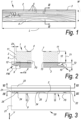
- Figures 7 to 10 show the pressing equipment 20 according to a second embodiment of the invention wherein the pressing device 23 is a continuous pressing device, where the floor element 1 advances in a predetermined advancing direction A during the pressing operation.
- the pressing position is movable with respect to the supporting structure 21.
- the pressing equipment 20 comprises a carrier 26, preferably a belt, adapted to move the floor element 1 along advancing direction A.
- the carrier 26 preferably, although not necessarily, substitutes the supporting plate 22 of the first embodiment.
- the pressing device 23 comprises a pressing belt.
- the centering device 25 is fixed in a predetermined position with respect to the belt of the pressing device 23. Moreover, the positioning device 24 is fixed in a predetermined position with respect to the carrier 26. Therefore, the positioning device 24 and the centering device 25 are movable along the advancing direction A.
- the positioning device 24 is substantially formed by a containing cavity 40 provided on the carrier 26, and the centering device 25 is substantially formed by a containing cavity 41 provided on the pressing device 23.
- Said containing cavity 40 of the positioning device 24 is defined by walls on which said contact surfaces 30 are provided.
- the containing cavity 41 of the centering device 25 is defined by walls on which said abutment surfaces 34 are provided.
- the walls of the cavities 40, 41 defining the positioning device 24 and the centering device 25 are formed by ribs 42 rising from a surface of the carrier 26 and of the pressing belt 23.
- said ribs 42 are made of polymeric material, preferably of a compressible material.
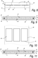
- Figure 11 shows a variant of the second embodiment wherein the centering device 25 and the positioning device 24 are formed in one piece by the same containing cavity 43.
- the walls defining the containing cavity 43 are shaped in such a way to define a lower narrow portion 44 of the cavity 43, for example suitable to contain the upper decorative layer 2, and an upper larger portion 45 of the cavity 43, for example suitable to contain the lower support layer 3.
- the floor element 1 is for example pressed upside down.
- the walls of the cavity 43 are formed by ribs 42 rising from a surface of the carrier 26.
- Preferably said ribs 42 are made of polymeric material, preferably of a compressible material.
- Figure 12 shows in a schematic view a plant 50, or a manufacturing line, for manufacturing a floor element 1.
- the plant 50 comprises one or more carriers 55 that transport the layers 2,3 of the floor element 1 through the plant 50 itself along an advancing direction A.
- This carrier 55 can coincide with the carrier 26 of the pressing equipment 20 or can be separated to the carrier 26 of the pressing equipment 20.
- the plant 50 can comprise an optical reader 57 configured to read a mark or sign provided on the support layer 3.
- Said mark or sign can identify one specific edge 8 and/or one specific coupling element 9,10 of the lower support layer to check if the lower support layer is provided with the correct orientation. Identifying the correct orientation of the support layer 3 is useful for correctly adjust the relative position between the lower support layer 3 and the upper decorative layer.
- the optical reader 57 can be substituted with any equivalent detecting means suitable to detect a mark or sign.
- the plant 50 comprises a gluing device 51 configured to provide a glue on the top surface lower support layer 3 on the carrier 55, thereby performing a step S1 of providing said glue in a method for manufacturing a floor element 1.
- the gluing device 51 comprises a sprayer having one or more nozzles for spraying the glue on said top surface. It is not excluded that in alternative embodiments the gluing device 51 comprises roller or other coating or gluing means.
- the gluing device 51 is configured to provide the glue in a pattern, but in alternative embodiment the gluing device 51 is configured to provide the glue as a uniform coating on the top surface of the lower support layer 3.
- the plant 50 further comprises a handling device 53, disposed downstream the gluing device 51, configured to stack the lower support layer 3 and the upper decorative layer 2 one upon the other in a stacking step S2 of the method.
- the handling device 53 comprises a pantograph 54, provided with gripping means to grab the decorative layer 2 and place it above the support layer 3 thereby stacking the two layers. In this stage the lower support layer 3 and the upper decorative layer 2 are not yet bonded each other and the mutual position can be adjusted in the pressing equipment 20.
- This handling device is completely optional and the two layer 2,3 can be stacked directly in the pressing equipment 20.
- the pressing equipment 20 Downstream of the handling device 53 is disposed the pressing equipment 20 that in the preferred embodiment is the stationary pressing device described above in figures from 3 to 6.
- the stacked layers 2,3 for forming the floor element 1 are provided to the pressing position at the pressing equipment 20.
- the positioning device 24 adjust the position of the lower support layer 3 on the pressing position at the pressing equipment 20.
- the centering device 25 then, adjust the position of the decorative layer 2 on the lower support layer 3.
- the positioning device 24 and the centering device 25 keep the position of the layers during a pressing step S3.
- the plant 50 can comprise a plurality of pressing equipment 20.
- the plant 50 further comprises a cleaning device 56, for example a brusher, configured to clean glue residues that eventually overflew beyond the edges of the layers 2,3 on the coupling elements.
- the cleaning device 56 is preferably disposed downstream the pressing equipment 20 in a cleaning step S4.
- the plant 50 further comprises a stocking area 52 disposed downstream the pressing equipment 20 where the floor elements 1 pressed in the pressing equipment 20 can rest during ageing and/or curing of the glue , before they are subjected to further processing steps like quality control check and packaging in a stocking step S5.
Landscapes
- Engineering & Computer Science (AREA)
- Mechanical Engineering (AREA)
- Floor Finish (AREA)
- Finishing Walls (AREA)
Claims (13)
- Druckausrüstung (20) zur Herstellung eines Bodenelements (1); wobei das Bodenelement eine obere Dekorschicht (2) und eine untere Stützschicht (3) umfasst; wobei die Ausrüstung das Folgende umfasst: eine Druckvorrichtung (23) zum Pressen der oberen Dekorschicht (2) auf die untere Stützschicht (3); eine Positioniervorrichtung (24), die dazu bestimmt ist, mindestens eine aus der unteren Stützschicht (3) und der oberen Dekorschicht (2) ausgewählte Schicht in einer Druckposition an der Druckvorrichtung (23) zu positionieren; und eine Zentriervorrichtung (25), die dazu bestimmt ist, die gegenseitige Position der oberen Dekorschicht (2) und der unteren Stützschicht (3) in der Druckposition zu justieren; wobei die Positioniervorrichtung (24) mindestens ein erstes Paar von Kontaktflächen (30) umfasst, die dazu ausgelegt sind, die gegenüberliegenden Kanten der Schicht zu berühren, die in die Druckposition gebracht werden soll; dadurch gekennzeichnet, dass die Positioniervorrichtung (24) mindestens ein bewegliches Element (31) umfasst, das dazu ausgelegt ist, den Abstand einzustellen, der sich zwischen den Kontaktflächen des Paares von Kontaktflächen (30) erstreckt.
- Druckausrüstung (20) nach Anspruch 1, wobei die Positioniervorrichtung (24) mit einem zweiten Paar von Kontaktflächen (30) ausgestattet ist, die dazu ausgelegt sind, mit gegenüberliegenden Kanten der zu positionierenden Schicht in Kontakt zu treten; wobei das erste und das zweite Paar von Kontaktflächen (30) vorzugsweise in einer Position angebracht sind, in der sie zueinander quer, vorzugsweise zueinander orthogonal, erstrecken.
- Druckausrüstung (20) nach Anspruch 2, wobei die Positioniervorrichtung (24) für jede Fläche des Flächenpaars ein bewegliches Element (31) umfasst.
- Druckausrüstung (20) nach Anspruch 3, wobei die beweglichen Elemente (31) für jedes Paar von Kontaktflächen (30) synchron bewegbar sind.
- Druckausrüstung (20) nach einem der vorhergehenden Ansprüche, wobei die Zentriervorrichtung (25) vorzugsweise zur Wechselwirkung mit nur einer Schicht ausgebildet ist, die aus der Stützschicht (3) und der Dekorschicht (2) ausgewählt ist; bevorzugt ist die Zentriervorrichtung (25) zur Wechselwirkung mit derjenigen Schicht des Bodenelements ausgebildet, die nicht mit der Positioniereinrichtung (24) in Wechselwirkung tritt.
- Druckausrüstung (20) nach Anspruch 5, wobei die Zentriervorrichtung (25) mindestens ein erstes Paar von Anschlagflächen (34) umfasst, die dazu ausgelegt sind, mit gegenüberliegenden Kanten der Schicht, die zentriert werden soll, in Kontakt zu treten.
- Druckausrüstung (20) nach Anspruch 6, wobei die Zentriervorrichtung (25) mindestens ein bewegliches Element (35) umfasst, das dazu ausgelegt ist, den Abstand einzustellen, der sich zwischen den Anschlagflächen des Paares von Anschlagflächen (34) erstreckt.
- Druckausrüstung (20) nach Anspruch 7, wobei die Zentriervorrichtung (25) ein bewegliches Element (35) für jede Anschlagfläche des Paares von Anschlagflächen (34) umfasst.
- Druckausrüstung (20) nach Anspruch 8, wobei die beweglichen Elemente (35) für jedes Paar von Anschlagflächen (34) synchron bewegt werden können.
- Druckausrüstung (20) nach Anspruch 7 und 1, wobei die beweglichen Elemente (35) der Zentriereinrichtung (25) unabhängig von den beweglichen Elementen (31) der Positioniereinrichtung (24) bewegt werden können.
- Druckausrüstung (20) nach einem der vorhergehenden Ansprüche, wobei die Zentriervorrichtung (25) fest mit der Positioniervorrichtung (24) verbunden ist.
- Druckausrüstung (20) nach einem der vorhergehenden Ansprüche, wobei die Druckvorrichtung (23) eine Anzahl von Druckelementen (39) umfasst; und wobei die Druckelemente (39) unabhängig voneinander gesteuert werden können und/oder in Gruppen von Druckelementen (39) gesteuert werden können.
- Anlage (50) zur Herstellung eines Bodenelements (1), wobei die Anlage (50) eine Druckausrüstung (20) nach einem der vorhergehenden Ansprüche umfasst, wobei die Anlage ferner ein Klebesystem (51) umfasst, das so konfiguriert ist, dass es einen Klebstoff auf einer Oberfläche der Dekorschicht (2) und/oder der unteren Stützschicht (3) bereitstellt, wobei die Klebevorrichtung (51) stromaufwärts von der Druckausrüstung (20) angebracht ist.
Applications Claiming Priority (2)
| Application Number | Priority Date | Filing Date | Title |
|---|---|---|---|
| US16/572,944 US11559961B2 (en) | 2019-09-17 | 2019-09-17 | Pressing equipment, a plant and a method for forming a floor element |
| PCT/US2020/050615 WO2021055261A1 (en) | 2019-09-17 | 2020-09-14 | A pressing equipment, a plant and a method for forming a floor element |
Publications (3)
| Publication Number | Publication Date |
|---|---|
| EP4031373A1 EP4031373A1 (de) | 2022-07-27 |
| EP4031373A4 EP4031373A4 (de) | 2023-10-18 |
| EP4031373B1 true EP4031373B1 (de) | 2025-02-26 |
Family
ID=74867889
Family Applications (1)
| Application Number | Title | Priority Date | Filing Date |
|---|---|---|---|
| EP20865386.5A Active EP4031373B1 (de) | 2019-09-17 | 2020-09-14 | Pressvorrichtung, anlage und verfahren zur herstellung eines bodenelements |
Country Status (8)
| Country | Link |
|---|---|
| US (2) | US11559961B2 (de) |
| EP (1) | EP4031373B1 (de) |
| CN (1) | CN114401843B (de) |
| BR (1) | BR112022002553A2 (de) |
| CA (1) | CA3146916A1 (de) |
| ES (1) | ES3025186T3 (de) |
| PL (1) | PL4031373T3 (de) |
| WO (1) | WO2021055261A1 (de) |
Families Citing this family (5)
| Publication number | Priority date | Publication date | Assignee | Title |
|---|---|---|---|---|
| BE1026355B1 (nl) * | 2018-06-06 | 2020-01-17 | Ivc Bvba | Vloerpanelen |
| US11959279B2 (en) * | 2020-02-12 | 2024-04-16 | Dal-Tile, Llc | Roof tile and a roof covering |
| CN112727006B (zh) * | 2020-12-30 | 2022-07-29 | 南京拓新冷暖科技有限公司 | 一种地暖保温板粘接线及其粘接方法 |
| US12291879B2 (en) * | 2021-12-29 | 2025-05-06 | Snap Lock Industries, Inc. | Method and apparatus for assembling a floor panel |
| CN114714741B (zh) * | 2022-05-11 | 2024-01-02 | 湖南机电职业技术学院 | 一种铝蜂窝复合板的成型装置 |
Family Cites Families (82)
| Publication number | Priority date | Publication date | Assignee | Title |
|---|---|---|---|---|
| US3521418A (en) | 1967-09-25 | 1970-07-21 | Ceramic Tile Walls Inc | Pre-finished decorative rigid panel |
| US3646180A (en) | 1969-10-24 | 1972-02-29 | Selectile Co Inc | Method of forming a foam cored wall panel having ceramic tile on one face |
| US3817012A (en) | 1970-09-15 | 1974-06-18 | American Olean Tile Co Inc | Ceramic tile panel construction |
| GB1472511A (en) | 1975-01-22 | 1977-05-04 | Falkenberg J | Manufacture of construction panels |
| US4567704A (en) | 1977-05-03 | 1986-02-04 | Tile Council Of America, Inc. | Resilient ceramic tile flooring |
| US4681786A (en) | 1980-03-18 | 1987-07-21 | Brown John G | Coverings providing impact sound isolation |
| IT1132252B (it) | 1980-07-25 | 1986-07-02 | Pirelli | Lastra per pavimentazione |
| DE3407443A1 (de) | 1984-02-29 | 1985-08-29 | Buchtal Gmbh Keramische Betriebe, 8472 Schwarzenfeld | Plattenfoermiges verbundelement |
| JPS61168560A (ja) | 1985-01-18 | 1986-07-30 | 日本碍子株式会社 | 高強度長石質磁器の製造法 |
| US4832995A (en) | 1985-10-21 | 1989-05-23 | Mclauchlin Dennis A | Laminated ceramic tile panel and process for producing same |
| CA1278500C (en) | 1986-05-01 | 1991-01-02 | Harold E. Mckelvey | Apparatus for use in the pre-pressing of laminated safety glass |
| NZ225505A (en) | 1987-07-22 | 1991-11-26 | Tonny Ernst Bergqvist | Press for manufacture of foamed plastics panels |
| JPH02175238A (ja) * | 1988-12-28 | 1990-07-06 | Jamco Corp | ハニカムパネルの連続成形方法 |
| US5199692A (en) * | 1990-03-24 | 1993-04-06 | Aioi Seiki, Inc. | Clamp device drive apparatus |
| JPH09158309A (ja) | 1995-12-11 | 1997-06-17 | Sekisui Chem Co Ltd | 床パネル |
| WO1997043089A1 (en) * | 1996-05-15 | 1997-11-20 | Ppg Industries, Inc. | Laminating device and method of operating same |
| US5937612A (en) | 1996-09-20 | 1999-08-17 | Jeda/America, Inc. | Reversible decorative tile and method finishing same in situ |
| DE19709088C2 (de) * | 1997-03-06 | 2000-05-11 | Wiemers Karl Heinz | Werkstückaufspanntisch |
| US6413618B1 (en) | 1999-05-11 | 2002-07-02 | Congoleum Corporation | Laminated glass floor tile and flooring made therefrom and method for making same |
| SE516696C2 (sv) | 1999-12-23 | 2002-02-12 | Perstorp Flooring Ab | Förfarande för framställning av ytelement vilka innefattar ett övre dekorativt skikt samt ytelement framställda enlit förfarandet |
| US6743318B2 (en) * | 2001-11-28 | 2004-06-01 | Masonite Corporation | Method of manufacturing consolidated cellulosic panels with contoured surfaces and variable basis weight |
| ES2254354T3 (es) | 2001-12-18 | 2006-06-16 | Bresciana Graniti S.P.A. | Baldosa compuesta para pavimentacion. |
| DE10201413A1 (de) | 2002-01-15 | 2003-07-24 | Buerkle Gmbh Robert | Verfahren und Vorrichtung zum Beschicken einer Plattenpresse |
| US7441384B2 (en) | 2002-08-14 | 2008-10-28 | Columbia Insurance Company | Pre-glued tongue and groove flooring |
| US20040031225A1 (en) | 2002-08-14 | 2004-02-19 | Gregory Fowler | Water resistant tongue and groove flooring |
| US20060111002A1 (en) | 2002-10-29 | 2006-05-25 | National Starch And Chemical Investment Holding Corporation | Fiberglass nonwoven binder |
| SE525630C2 (sv) | 2002-11-13 | 2005-03-22 | Kaehr Ab G | Golvskiva och golvbeläggning för fjädrande golv |
| US7393583B1 (en) | 2003-04-14 | 2008-07-01 | Starquartz Industries, Inc. | Flooring tile |
| US7442423B2 (en) | 2003-04-28 | 2008-10-28 | Shaw Industries Group | Hard surface-veneer engineered surfacing tiles |
| US7550192B2 (en) | 2003-04-30 | 2009-06-23 | Congoleum Corporation | Resilient floor tile |
| BE1015760A6 (nl) | 2003-06-04 | 2005-08-02 | Flooring Ind Ltd | Vloerpaneel en werkwijze voor het vervaardigen van dergelijk vloerpaneel. |
| CN1250403C (zh) | 2003-06-18 | 2006-04-12 | 哈尔滨商业大学 | 植物纤维铅笔材料及其制作方法 |
| DE10349790A1 (de) | 2003-10-24 | 2005-05-25 | Petec S.A. | Bauelement zur Herstellung von Boden- oder Wandverkleidungen |
| SE526984C2 (sv) * | 2003-11-13 | 2005-11-29 | Pergo Europ Ab | Förfarande för tillverkning av dekorativt laminat |
| US7984660B2 (en) | 2004-07-23 | 2011-07-26 | Scott Roger Nathan | Pipeline sampling device |
| DE102004045398B3 (de) | 2004-09-18 | 2006-05-04 | Faurecia Innenraum Systeme Gmbh | Verfahren zur Herstellung eines Bauteils aus zumindest zwei Schichten sowie eine Vorrichtung zur Durchführung des Verfahrens |
| US8201377B2 (en) | 2004-11-05 | 2012-06-19 | Faus Group, Inc. | Flooring system having multiple alignment points |
| BE1016394A3 (nl) * | 2004-12-23 | 2006-10-03 | Flooring Ind Ltd | Vloerpaneel, alsmede werkwijze, inrichting en accessoires voor het vervaardigen van zulk vloerpaneel. |
| DE102005006532A1 (de) | 2005-02-11 | 2006-08-24 | Kaindl Flooring Gmbh | Paneel mit dekorativer Schicht |
| CN100374291C (zh) * | 2005-08-17 | 2008-03-12 | 杭州森佳木业制造厂 | 仿真木纹地板及压贴工艺和设备 |
| US20070289236A1 (en) | 2006-06-14 | 2007-12-20 | Yong Ho Choi | Finishing panel using marble |
| BE1017350A6 (nl) | 2006-10-31 | 2008-06-03 | Flooring Ind Ltd | Vloerpaneel en vloerbekleding bestaande uit dergelijke vloerpanelen. |
| US7984600B2 (en) | 2007-02-02 | 2011-07-26 | Mohawk Carpet Corporation | Groutless tile system and method for making the same |
| RU69117U1 (ru) | 2007-07-31 | 2007-12-10 | Михаил Юрьевич Черкасов | Паркетная доска (варианты) |
| US9783996B2 (en) | 2007-11-19 | 2017-10-10 | Valinge Innovation Ab | Fibre based panels with a wear resistance surface |
| KR101050399B1 (ko) | 2008-05-20 | 2011-07-19 | 현대산업개발 주식회사 | 복수의 방수시트를 이용한 방수공법 |
| US8591460B2 (en) | 2008-06-13 | 2013-11-26 | Cardiosolutions, Inc. | Steerable catheter and dilator and system and method for implanting a heart implant |
| EA013033B1 (ru) | 2008-12-11 | 2010-02-26 | Артур Робертович Кочаров | Станок для форматной обработки паркетных блоков |
| ITMO20080330A1 (it) | 2008-12-24 | 2010-06-25 | Mariano Paganelli | Procedimento per realizzare piastrelle ad alta resistenza destinate al rivestimento di pavimentazioni e di pareti interne o esterne. |
| BE1018627A5 (nl) | 2009-01-16 | 2011-05-03 | Flooring Ind Ltd Sarl | Vloerpaneel. |
| US8741085B2 (en) | 2009-08-21 | 2014-06-03 | Awi Licensing Company | Method of making a resilient floor tile |
| DE102009042057A1 (de) | 2009-09-10 | 2011-03-24 | Sig Technology Ag | Vorrichtung und Verfahren zum Verpressen |
| KR20110064350A (ko) | 2009-12-08 | 2011-06-15 | 주식회사 세화스톤 | 석재 접합식 타일 |
| CN101881076B (zh) | 2010-06-09 | 2014-07-09 | 黄焕文 | 一种方便铺的组合式地板 |
| EP2369090B1 (de) | 2010-03-16 | 2015-10-07 | Fligo Flooring Innovation Group AB | Modulare Fußbodensubstrat |
| CA2796938A1 (en) | 2010-04-02 | 2011-10-06 | Stonexpress, Inc. | Thin-tile laminated mosaic sheet |
| US8925275B2 (en) | 2010-05-10 | 2015-01-06 | Flooring Industries Limited, Sarl | Floor panel |
| BE1019501A5 (nl) | 2010-05-10 | 2012-08-07 | Flooring Ind Ltd Sarl | Vloerpaneel en werkwijze voor het vervaardigen van vloerpanelen. |
| US9636892B2 (en) | 2010-05-25 | 2017-05-02 | Dubon Associates, Inc. | Thin floor tiles |
| US8613182B2 (en) | 2010-06-15 | 2013-12-24 | Joseph D. D'Agostino | Ceramic tile floor |
| KR101198942B1 (ko) | 2010-07-20 | 2012-11-07 | 주식회사 이지테크 | 마감용 판재 |
| CN102454278B (zh) | 2010-10-26 | 2014-06-04 | 上海劲嘉建材科技有限公司 | 自粘地砖及其制造方法 |
| CN102011475B (zh) | 2010-11-08 | 2012-10-24 | 四川升达林业产业股份有限公司 | 具有三维装饰纹理结构的强化木地板及其制造方法 |
| US8461249B2 (en) | 2010-11-14 | 2013-06-11 | Sabic Innovative Plastics Ip B.V. | Compositions and articles of manufacture containing branched polycarbonate |
| CN202097790U (zh) | 2011-05-26 | 2012-01-04 | 安徽扬子地板股份有限公司 | 地板热压机 |
| BE1020072A5 (nl) | 2011-07-12 | 2013-04-02 | Flooring Ind Ltd Sarl | Werkwijzen voor het vervaardigen van laminaatpanelen. |
| US9556619B2 (en) | 2011-10-21 | 2017-01-31 | Old Mill Brick Incorporated | Fiber enforced thin brick sheet and process |
| WO2013118030A2 (en) | 2012-02-07 | 2013-08-15 | Flooring Industries Limited, Sarl | Floor panel for forming a floor covering, floor covering formed from such floor panels and method for manufacturing such floor panels. |
| BE1020722A3 (nl) | 2012-06-01 | 2014-04-01 | Unilin Bvba | Paneel voor het vormen van een vloerbekleding en werkwijze voor het vervaardigen van dergelijke panelen. |
| US9511573B2 (en) * | 2013-07-25 | 2016-12-06 | Masonite Corporation | Automated door assembly, press, and adhesive therefor |
| US20160288447A1 (en) | 2015-01-05 | 2016-10-06 | Eurico Januario Cordeiro | Waterproof composite core |
| CN104626322B (zh) | 2015-02-10 | 2016-07-06 | 四川升达林业产业股份有限公司 | 低强度损失的槽型强化木地板制造方法 |
| BE1023310B1 (nl) | 2015-07-02 | 2017-01-31 | Unilin, Bvba | Vloerpaneel en werkwijze voor het vervaardigen van vloerpanelen. |
| WO2017013501A1 (en) | 2015-07-23 | 2017-01-26 | Floover World S.L. | Prefabricated element for flooring |
| PL3130464T3 (pl) | 2015-08-12 | 2020-11-02 | Hpc Solutions Ag | Sposób i urządzenie do wytwarzania okładziny podłogowej z płytami kamiennymi |
| GB2543637B (en) * | 2015-09-11 | 2018-08-08 | Jeld Wen Uk Ltd | Method and system for assembly of recessed panel doors |
| US10704268B2 (en) | 2016-11-08 | 2020-07-07 | Mannington Mills, Inc. | Adhesive-backed flooring panel, system, and method |
| CN106743519A (zh) | 2017-01-12 | 2017-05-31 | 江苏欧圣木业有限公司 | 加工强化地板的热压机的送料机构 |
| EP3404165B1 (de) | 2017-05-15 | 2021-10-13 | Flooring Industries Limited, SARL | Fussbodenelement zur formung eines fussbodenbelags sowie fussbodenbelag |
| CN109986334B (zh) | 2017-12-29 | 2024-07-26 | 浙江拓为汽车部件有限公司 | 一种压衬套设备预定位机构及无损压制衬套方法 |
| US10563411B2 (en) | 2018-07-06 | 2020-02-18 | Daltile Corporation | Floor element for forming a floor covering, a floor covering, and a method for manufacturing a floor element |
| US11691394B2 (en) * | 2019-08-14 | 2023-07-04 | Pet Decorator, LLC | Pet resistant engineered hardwood floor and method of making |
-
2019
- 2019-09-17 US US16/572,944 patent/US11559961B2/en active Active
-
2020
- 2020-09-14 US US17/642,271 patent/US12115748B2/en active Active
- 2020-09-14 EP EP20865386.5A patent/EP4031373B1/de active Active
- 2020-09-14 CN CN202080065121.8A patent/CN114401843B/zh active Active
- 2020-09-14 CA CA3146916A patent/CA3146916A1/en active Pending
- 2020-09-14 ES ES20865386T patent/ES3025186T3/es active Active
- 2020-09-14 PL PL20865386.5T patent/PL4031373T3/pl unknown
- 2020-09-14 BR BR112022002553A patent/BR112022002553A2/pt active IP Right Grant
- 2020-09-14 WO PCT/US2020/050615 patent/WO2021055261A1/en not_active Ceased
Also Published As
| Publication number | Publication date |
|---|---|
| EP4031373A1 (de) | 2022-07-27 |
| US20220297404A1 (en) | 2022-09-22 |
| PL4031373T3 (pl) | 2025-05-19 |
| CN114401843B (zh) | 2024-12-13 |
| US12115748B2 (en) | 2024-10-15 |
| BR112022002553A2 (pt) | 2022-07-19 |
| EP4031373A4 (de) | 2023-10-18 |
| US11559961B2 (en) | 2023-01-24 |
| CN114401843A (zh) | 2022-04-26 |
| CA3146916A1 (en) | 2021-03-25 |
| US20210078279A1 (en) | 2021-03-18 |
| WO2021055261A1 (en) | 2021-03-25 |
| ES3025186T3 (en) | 2025-06-06 |
Similar Documents
| Publication | Publication Date | Title |
|---|---|---|
| EP4031373B1 (de) | Pressvorrichtung, anlage und verfahren zur herstellung eines bodenelements | |
| US7989050B2 (en) | Building slab, floor panels in particular, and method of manufacturing the same | |
| RU2561327C2 (ru) | Способ изготовления половой доски | |
| EP2812509B1 (de) | Bodenfliese | |
| KR101407050B1 (ko) | 가변형 수조 적층방식을 이용한 3차원 프린터 및 이를 이용한 조형방법 | |
| EP3099478B1 (de) | Verfahren zur herstellung eines kontinuierliches pressband für keramikfliesen mit strukturierter oberfläche | |
| KR102847278B1 (ko) | 장식 디자인을 구비한 기판의 제조 시스템 | |
| CN103786408B (zh) | 一种人造板连续生产线的生产工艺 | |
| US12269058B2 (en) | Board edge casting process and application thereof | |
| KR101266305B1 (ko) | 평면기판에 마이크로 요철패턴이 형성된 유브이수지층 코팅방법 및 이에 사용되는 지그 | |
| KR20130053002A (ko) | Uv 패턴 롤 제조방법 | |
| CN120225326A (zh) | 用于对工件进行覆层的设备和方法 | |
| WO2005092638A2 (en) | Method to produce a covering modular panel, and modular panel thus obtained | |
| KR20180040347A (ko) | 리얼우드 내장재 및 이의 제조방법 | |
| KR102239803B1 (ko) | 리얼우드 내장재의 제조방법 | |
| JPH1190904A (ja) | ベニヤ単板の縦はぎ装置 | |
| JP3109784B2 (ja) | 木質材木口面の処理方法及び装置 | |
| CN108638398A (zh) | 一种异形件模具的制作工艺 | |
| JPH01253441A (ja) | 化粧板及びその製造方法、製造装置 | |
| WO2024154027A1 (en) | Method and plant for manufacturing slabs made of stone or stone-like agglomerate material and having veins and surface chromatic effects and slab so obtained | |
| CN121335809A (zh) | 包括工程石材的装饰元件和用于制造包括工程石材的装饰元件的方法 | |
| JP4377179B2 (ja) | 無機質化粧板の製造方法 | |
| CN116587378A (zh) | 一种多层木板及其加工工艺 | |
| JPH0482713A (ja) | 模様付ブロックの製造方法 | |
| ITVA20120026A1 (it) | Macchina per incollaggio di tamponi abrasivi. |
Legal Events
| Date | Code | Title | Description |
|---|---|---|---|
| STAA | Information on the status of an ep patent application or granted ep patent |
Free format text: STATUS: THE INTERNATIONAL PUBLICATION HAS BEEN MADE |
|
| PUAI | Public reference made under article 153(3) epc to a published international application that has entered the european phase |
Free format text: ORIGINAL CODE: 0009012 |
|
| STAA | Information on the status of an ep patent application or granted ep patent |
Free format text: STATUS: REQUEST FOR EXAMINATION WAS MADE |
|
| 17P | Request for examination filed |
Effective date: 20220223 |
|
| AK | Designated contracting states |
Kind code of ref document: A1 Designated state(s): AL AT BE BG CH CY CZ DE DK EE ES FI FR GB GR HR HU IE IS IT LI LT LU LV MC MK MT NL NO PL PT RO RS SE SI SK SM TR |
|
| DAV | Request for validation of the european patent (deleted) | ||
| DAX | Request for extension of the european patent (deleted) | ||
| A4 | Supplementary search report drawn up and despatched |
Effective date: 20230920 |
|
| RIC1 | Information provided on ipc code assigned before grant |
Ipc: B30B 1/32 20060101ALI20230914BHEP Ipc: B32B 38/18 20060101ALI20230914BHEP Ipc: E04F 15/02 20060101ALI20230914BHEP Ipc: B32B 37/10 20060101AFI20230914BHEP |
|
| RAP3 | Party data changed (applicant data changed or rights of an application transferred) |
Owner name: DAL-TILE, LLC |
|
| REG | Reference to a national code |
Ref country code: DE Ref legal event code: R079 Free format text: PREVIOUS MAIN CLASS: B32B0037100000 Ipc: B32B0037120000 Ref document number: 602020046951 Country of ref document: DE |
|
| GRAP | Despatch of communication of intention to grant a patent |
Free format text: ORIGINAL CODE: EPIDOSNIGR1 |
|
| STAA | Information on the status of an ep patent application or granted ep patent |
Free format text: STATUS: GRANT OF PATENT IS INTENDED |
|
| RIC1 | Information provided on ipc code assigned before grant |
Ipc: E04F 15/02 20060101ALI20240605BHEP Ipc: B32B 38/18 20060101ALI20240605BHEP Ipc: B30B 1/32 20060101ALI20240605BHEP Ipc: B32B 37/10 20060101ALI20240605BHEP Ipc: B30B 5/06 20060101ALI20240605BHEP Ipc: B30B 9/28 20060101ALI20240605BHEP Ipc: B30B 3/00 20060101ALI20240605BHEP Ipc: B30B 15/30 20060101ALI20240605BHEP Ipc: E04F 15/08 20060101ALI20240605BHEP Ipc: B32B 37/12 20060101AFI20240605BHEP |
|
| INTG | Intention to grant announced |
Effective date: 20240704 |
|
| GRAJ | Information related to disapproval of communication of intention to grant by the applicant or resumption of examination proceedings by the epo deleted |
Free format text: ORIGINAL CODE: EPIDOSDIGR1 |
|
| STAA | Information on the status of an ep patent application or granted ep patent |
Free format text: STATUS: REQUEST FOR EXAMINATION WAS MADE |
|
| GRAP | Despatch of communication of intention to grant a patent |
Free format text: ORIGINAL CODE: EPIDOSNIGR1 |
|
| STAA | Information on the status of an ep patent application or granted ep patent |
Free format text: STATUS: GRANT OF PATENT IS INTENDED |
|
| INTC | Intention to grant announced (deleted) | ||
| RIC1 | Information provided on ipc code assigned before grant |
Ipc: E04F 15/08 20060101ALI20240926BHEP Ipc: B30B 15/30 20060101ALI20240926BHEP Ipc: B30B 3/00 20060101ALI20240926BHEP Ipc: B30B 9/28 20060101ALI20240926BHEP Ipc: B30B 5/06 20060101ALI20240926BHEP Ipc: B32B 37/10 20060101ALI20240926BHEP Ipc: B30B 1/32 20060101ALI20240926BHEP Ipc: B32B 38/18 20060101ALI20240926BHEP Ipc: E04F 15/02 20060101ALI20240926BHEP Ipc: B30B 15/08 20060101ALI20240926BHEP Ipc: B32B 37/12 20060101AFI20240926BHEP |
|
| INTG | Intention to grant announced |
Effective date: 20241010 |
|
| GRAS | Grant fee paid |
Free format text: ORIGINAL CODE: EPIDOSNIGR3 |
|
| GRAA | (expected) grant |
Free format text: ORIGINAL CODE: 0009210 |
|
| STAA | Information on the status of an ep patent application or granted ep patent |
Free format text: STATUS: THE PATENT HAS BEEN GRANTED |
|
| P01 | Opt-out of the competence of the unified patent court (upc) registered |
Free format text: CASE NUMBER: APP_406/2025 Effective date: 20250106 |
|
| AK | Designated contracting states |
Kind code of ref document: B1 Designated state(s): AL AT BE BG CH CY CZ DE DK EE ES FI FR GB GR HR HU IE IS IT LI LT LU LV MC MK MT NL NO PL PT RO RS SE SI SK SM TR |
|
| REG | Reference to a national code |
Ref country code: GB Ref legal event code: FG4D |
|
| REG | Reference to a national code |
Ref country code: CH Ref legal event code: EP |
|
| REG | Reference to a national code |
Ref country code: DE Ref legal event code: R096 Ref document number: 602020046951 Country of ref document: DE |
|
| REG | Reference to a national code |
Ref country code: IE Ref legal event code: FG4D |
|
| REG | Reference to a national code |
Ref country code: ES Ref legal event code: FG2A Ref document number: 3025186 Country of ref document: ES Kind code of ref document: T3 Effective date: 20250606 |
|
| REG | Reference to a national code |
Ref country code: NL Ref legal event code: MP Effective date: 20250226 |
|
| PG25 | Lapsed in a contracting state [announced via postgrant information from national office to epo] |
Ref country code: RS Free format text: LAPSE BECAUSE OF FAILURE TO SUBMIT A TRANSLATION OF THE DESCRIPTION OR TO PAY THE FEE WITHIN THE PRESCRIBED TIME-LIMIT Effective date: 20250526 |
|
| PG25 | Lapsed in a contracting state [announced via postgrant information from national office to epo] |
Ref country code: FI Free format text: LAPSE BECAUSE OF FAILURE TO SUBMIT A TRANSLATION OF THE DESCRIPTION OR TO PAY THE FEE WITHIN THE PRESCRIBED TIME-LIMIT Effective date: 20250226 |
|
| REG | Reference to a national code |
Ref country code: LT Ref legal event code: MG9D |
|
| PG25 | Lapsed in a contracting state [announced via postgrant information from national office to epo] |
Ref country code: NO Free format text: LAPSE BECAUSE OF FAILURE TO SUBMIT A TRANSLATION OF THE DESCRIPTION OR TO PAY THE FEE WITHIN THE PRESCRIBED TIME-LIMIT Effective date: 20250526 Ref country code: IS Free format text: LAPSE BECAUSE OF FAILURE TO SUBMIT A TRANSLATION OF THE DESCRIPTION OR TO PAY THE FEE WITHIN THE PRESCRIBED TIME-LIMIT Effective date: 20250626 |
|
| PG25 | Lapsed in a contracting state [announced via postgrant information from national office to epo] |
Ref country code: NL Free format text: LAPSE BECAUSE OF FAILURE TO SUBMIT A TRANSLATION OF THE DESCRIPTION OR TO PAY THE FEE WITHIN THE PRESCRIBED TIME-LIMIT Effective date: 20250226 |
|
| PG25 | Lapsed in a contracting state [announced via postgrant information from national office to epo] |
Ref country code: HR Free format text: LAPSE BECAUSE OF FAILURE TO SUBMIT A TRANSLATION OF THE DESCRIPTION OR TO PAY THE FEE WITHIN THE PRESCRIBED TIME-LIMIT Effective date: 20250226 |
|
| PG25 | Lapsed in a contracting state [announced via postgrant information from national office to epo] |
Ref country code: LV Free format text: LAPSE BECAUSE OF FAILURE TO SUBMIT A TRANSLATION OF THE DESCRIPTION OR TO PAY THE FEE WITHIN THE PRESCRIBED TIME-LIMIT Effective date: 20250226 Ref country code: PT Free format text: LAPSE BECAUSE OF FAILURE TO SUBMIT A TRANSLATION OF THE DESCRIPTION OR TO PAY THE FEE WITHIN THE PRESCRIBED TIME-LIMIT Effective date: 20250626 |
|
| PG25 | Lapsed in a contracting state [announced via postgrant information from national office to epo] |
Ref country code: GR Free format text: LAPSE BECAUSE OF FAILURE TO SUBMIT A TRANSLATION OF THE DESCRIPTION OR TO PAY THE FEE WITHIN THE PRESCRIBED TIME-LIMIT Effective date: 20250527 Ref country code: BG Free format text: LAPSE BECAUSE OF FAILURE TO SUBMIT A TRANSLATION OF THE DESCRIPTION OR TO PAY THE FEE WITHIN THE PRESCRIBED TIME-LIMIT Effective date: 20250226 |
|
| REG | Reference to a national code |
Ref country code: AT Ref legal event code: MK05 Ref document number: 1770266 Country of ref document: AT Kind code of ref document: T Effective date: 20250226 |
|
| PG25 | Lapsed in a contracting state [announced via postgrant information from national office to epo] |
Ref country code: SE Free format text: LAPSE BECAUSE OF FAILURE TO SUBMIT A TRANSLATION OF THE DESCRIPTION OR TO PAY THE FEE WITHIN THE PRESCRIBED TIME-LIMIT Effective date: 20250226 |
|
| PG25 | Lapsed in a contracting state [announced via postgrant information from national office to epo] |
Ref country code: SM Free format text: LAPSE BECAUSE OF FAILURE TO SUBMIT A TRANSLATION OF THE DESCRIPTION OR TO PAY THE FEE WITHIN THE PRESCRIBED TIME-LIMIT Effective date: 20250226 |
|
| PG25 | Lapsed in a contracting state [announced via postgrant information from national office to epo] |
Ref country code: DK Free format text: LAPSE BECAUSE OF FAILURE TO SUBMIT A TRANSLATION OF THE DESCRIPTION OR TO PAY THE FEE WITHIN THE PRESCRIBED TIME-LIMIT Effective date: 20250226 |
|
| PGFP | Annual fee paid to national office [announced via postgrant information from national office to epo] |
Ref country code: DE Payment date: 20250929 Year of fee payment: 6 |
|
| PGFP | Annual fee paid to national office [announced via postgrant information from national office to epo] |
Ref country code: TR Payment date: 20250822 Year of fee payment: 6 Ref country code: PL Payment date: 20250819 Year of fee payment: 6 Ref country code: IT Payment date: 20250919 Year of fee payment: 6 |
|
| PG25 | Lapsed in a contracting state [announced via postgrant information from national office to epo] |
Ref country code: AT Free format text: LAPSE BECAUSE OF FAILURE TO SUBMIT A TRANSLATION OF THE DESCRIPTION OR TO PAY THE FEE WITHIN THE PRESCRIBED TIME-LIMIT Effective date: 20250226 |
|
| PG25 | Lapsed in a contracting state [announced via postgrant information from national office to epo] |
Ref country code: EE Free format text: LAPSE BECAUSE OF FAILURE TO SUBMIT A TRANSLATION OF THE DESCRIPTION OR TO PAY THE FEE WITHIN THE PRESCRIBED TIME-LIMIT Effective date: 20250226 Ref country code: CZ Free format text: LAPSE BECAUSE OF FAILURE TO SUBMIT A TRANSLATION OF THE DESCRIPTION OR TO PAY THE FEE WITHIN THE PRESCRIBED TIME-LIMIT Effective date: 20250226 |
|
| PG25 | Lapsed in a contracting state [announced via postgrant information from national office to epo] |
Ref country code: RO Free format text: LAPSE BECAUSE OF FAILURE TO SUBMIT A TRANSLATION OF THE DESCRIPTION OR TO PAY THE FEE WITHIN THE PRESCRIBED TIME-LIMIT Effective date: 20250226 |
|
| PG25 | Lapsed in a contracting state [announced via postgrant information from national office to epo] |
Ref country code: SK Free format text: LAPSE BECAUSE OF FAILURE TO SUBMIT A TRANSLATION OF THE DESCRIPTION OR TO PAY THE FEE WITHIN THE PRESCRIBED TIME-LIMIT Effective date: 20250226 |
|
| REG | Reference to a national code |
Ref country code: DE Ref legal event code: R097 Ref document number: 602020046951 Country of ref document: DE |
|
| PLBE | No opposition filed within time limit |
Free format text: ORIGINAL CODE: 0009261 |
|
| STAA | Information on the status of an ep patent application or granted ep patent |
Free format text: STATUS: NO OPPOSITION FILED WITHIN TIME LIMIT |
|
| PGFP | Annual fee paid to national office [announced via postgrant information from national office to epo] |
Ref country code: ES Payment date: 20251001 Year of fee payment: 6 |
|
| 26N | No opposition filed |
Effective date: 20251127 |