EP4030122B1 - Outdoor unit and refrigeration cycle apparatus - Google Patents
Outdoor unit and refrigeration cycle apparatus Download PDFInfo
- Publication number
- EP4030122B1 EP4030122B1 EP19944933.1A EP19944933A EP4030122B1 EP 4030122 B1 EP4030122 B1 EP 4030122B1 EP 19944933 A EP19944933 A EP 19944933A EP 4030122 B1 EP4030122 B1 EP 4030122B1
- Authority
- EP
- European Patent Office
- Prior art keywords
- refrigerant
- flow path
- outdoor unit
- expansion valve
- condenser
- Prior art date
- Legal status (The legal status is an assumption and is not a legal conclusion. Google has not performed a legal analysis and makes no representation as to the accuracy of the status listed.)
- Active
Links
- 238000005057 refrigeration Methods 0.000 title claims description 32
- 239000003507 refrigerant Substances 0.000 claims description 187
- 238000001514 detection method Methods 0.000 claims description 13
- CURLTUGMZLYLDI-UHFFFAOYSA-N Carbon dioxide Chemical group O=C=O CURLTUGMZLYLDI-UHFFFAOYSA-N 0.000 claims description 6
- 229910002092 carbon dioxide Inorganic materials 0.000 claims description 4
- 239000001569 carbon dioxide Substances 0.000 claims description 2
- 230000007423 decrease Effects 0.000 description 14
- 239000007788 liquid Substances 0.000 description 14
- 238000012545 processing Methods 0.000 description 9
- 238000002347 injection Methods 0.000 description 7
- 239000007924 injection Substances 0.000 description 7
- 238000010586 diagram Methods 0.000 description 4
- 238000000034 method Methods 0.000 description 3
- 239000000872 buffer Substances 0.000 description 2
- 230000015556 catabolic process Effects 0.000 description 2
- 238000006731 degradation reaction Methods 0.000 description 2
- 239000007791 liquid phase Substances 0.000 description 2
- 239000012071 phase Substances 0.000 description 2
- 238000013459 approach Methods 0.000 description 1
- 238000007664 blowing Methods 0.000 description 1
- 238000006243 chemical reaction Methods 0.000 description 1
- 238000004891 communication Methods 0.000 description 1
- 238000007906 compression Methods 0.000 description 1
- 238000013461 design Methods 0.000 description 1
- 230000000694 effects Effects 0.000 description 1
- 230000017525 heat dissipation Effects 0.000 description 1
- 239000004973 liquid crystal related substance Substances 0.000 description 1
- 238000012986 modification Methods 0.000 description 1
- 230000004048 modification Effects 0.000 description 1
- 230000002250 progressing effect Effects 0.000 description 1
- 239000000243 solution Substances 0.000 description 1
- 238000010792 warming Methods 0.000 description 1
Images


Classifications
-
- F—MECHANICAL ENGINEERING; LIGHTING; HEATING; WEAPONS; BLASTING
- F25—REFRIGERATION OR COOLING; COMBINED HEATING AND REFRIGERATION SYSTEMS; HEAT PUMP SYSTEMS; MANUFACTURE OR STORAGE OF ICE; LIQUEFACTION SOLIDIFICATION OF GASES
- F25B—REFRIGERATION MACHINES, PLANTS OR SYSTEMS; COMBINED HEATING AND REFRIGERATION SYSTEMS; HEAT PUMP SYSTEMS
- F25B49/00—Arrangement or mounting of control or safety devices
- F25B49/02—Arrangement or mounting of control or safety devices for compression type machines, plants or systems
-
- F—MECHANICAL ENGINEERING; LIGHTING; HEATING; WEAPONS; BLASTING
- F25—REFRIGERATION OR COOLING; COMBINED HEATING AND REFRIGERATION SYSTEMS; HEAT PUMP SYSTEMS; MANUFACTURE OR STORAGE OF ICE; LIQUEFACTION SOLIDIFICATION OF GASES
- F25B—REFRIGERATION MACHINES, PLANTS OR SYSTEMS; COMBINED HEATING AND REFRIGERATION SYSTEMS; HEAT PUMP SYSTEMS
- F25B1/00—Compression machines, plants or systems with non-reversible cycle
- F25B1/10—Compression machines, plants or systems with non-reversible cycle with multi-stage compression
-
- F—MECHANICAL ENGINEERING; LIGHTING; HEATING; WEAPONS; BLASTING
- F25—REFRIGERATION OR COOLING; COMBINED HEATING AND REFRIGERATION SYSTEMS; HEAT PUMP SYSTEMS; MANUFACTURE OR STORAGE OF ICE; LIQUEFACTION SOLIDIFICATION OF GASES
- F25B—REFRIGERATION MACHINES, PLANTS OR SYSTEMS; COMBINED HEATING AND REFRIGERATION SYSTEMS; HEAT PUMP SYSTEMS
- F25B41/00—Fluid-circulation arrangements
- F25B41/30—Expansion means; Dispositions thereof
-
- F—MECHANICAL ENGINEERING; LIGHTING; HEATING; WEAPONS; BLASTING
- F25—REFRIGERATION OR COOLING; COMBINED HEATING AND REFRIGERATION SYSTEMS; HEAT PUMP SYSTEMS; MANUFACTURE OR STORAGE OF ICE; LIQUEFACTION SOLIDIFICATION OF GASES
- F25B—REFRIGERATION MACHINES, PLANTS OR SYSTEMS; COMBINED HEATING AND REFRIGERATION SYSTEMS; HEAT PUMP SYSTEMS
- F25B49/00—Arrangement or mounting of control or safety devices
- F25B49/005—Arrangement or mounting of control or safety devices of safety devices
-
- F—MECHANICAL ENGINEERING; LIGHTING; HEATING; WEAPONS; BLASTING
- F25—REFRIGERATION OR COOLING; COMBINED HEATING AND REFRIGERATION SYSTEMS; HEAT PUMP SYSTEMS; MANUFACTURE OR STORAGE OF ICE; LIQUEFACTION SOLIDIFICATION OF GASES
- F25B—REFRIGERATION MACHINES, PLANTS OR SYSTEMS; COMBINED HEATING AND REFRIGERATION SYSTEMS; HEAT PUMP SYSTEMS
- F25B2309/00—Gas cycle refrigeration machines
- F25B2309/06—Compression machines, plants or systems characterised by the refrigerant being carbon dioxide
- F25B2309/061—Compression machines, plants or systems characterised by the refrigerant being carbon dioxide with cycle highest pressure above the supercritical pressure
-
- F—MECHANICAL ENGINEERING; LIGHTING; HEATING; WEAPONS; BLASTING
- F25—REFRIGERATION OR COOLING; COMBINED HEATING AND REFRIGERATION SYSTEMS; HEAT PUMP SYSTEMS; MANUFACTURE OR STORAGE OF ICE; LIQUEFACTION SOLIDIFICATION OF GASES
- F25B—REFRIGERATION MACHINES, PLANTS OR SYSTEMS; COMBINED HEATING AND REFRIGERATION SYSTEMS; HEAT PUMP SYSTEMS
- F25B2400/00—General features or devices for refrigeration machines, plants or systems, combined heating and refrigeration systems or heat-pump systems, i.e. not limited to a particular subgroup of F25B
- F25B2400/04—Refrigeration circuit bypassing means
- F25B2400/0409—Refrigeration circuit bypassing means for the evaporator
-
- F—MECHANICAL ENGINEERING; LIGHTING; HEATING; WEAPONS; BLASTING
- F25—REFRIGERATION OR COOLING; COMBINED HEATING AND REFRIGERATION SYSTEMS; HEAT PUMP SYSTEMS; MANUFACTURE OR STORAGE OF ICE; LIQUEFACTION SOLIDIFICATION OF GASES
- F25B—REFRIGERATION MACHINES, PLANTS OR SYSTEMS; COMBINED HEATING AND REFRIGERATION SYSTEMS; HEAT PUMP SYSTEMS
- F25B2400/00—General features or devices for refrigeration machines, plants or systems, combined heating and refrigeration systems or heat-pump systems, i.e. not limited to a particular subgroup of F25B
- F25B2400/16—Receivers
-
- F—MECHANICAL ENGINEERING; LIGHTING; HEATING; WEAPONS; BLASTING
- F25—REFRIGERATION OR COOLING; COMBINED HEATING AND REFRIGERATION SYSTEMS; HEAT PUMP SYSTEMS; MANUFACTURE OR STORAGE OF ICE; LIQUEFACTION SOLIDIFICATION OF GASES
- F25B—REFRIGERATION MACHINES, PLANTS OR SYSTEMS; COMBINED HEATING AND REFRIGERATION SYSTEMS; HEAT PUMP SYSTEMS
- F25B2400/00—General features or devices for refrigeration machines, plants or systems, combined heating and refrigeration systems or heat-pump systems, i.e. not limited to a particular subgroup of F25B
- F25B2400/23—Separators
-
- F—MECHANICAL ENGINEERING; LIGHTING; HEATING; WEAPONS; BLASTING
- F25—REFRIGERATION OR COOLING; COMBINED HEATING AND REFRIGERATION SYSTEMS; HEAT PUMP SYSTEMS; MANUFACTURE OR STORAGE OF ICE; LIQUEFACTION SOLIDIFICATION OF GASES
- F25B—REFRIGERATION MACHINES, PLANTS OR SYSTEMS; COMBINED HEATING AND REFRIGERATION SYSTEMS; HEAT PUMP SYSTEMS
- F25B2500/00—Problems to be solved
- F25B2500/19—Calculation of parameters
-
- F—MECHANICAL ENGINEERING; LIGHTING; HEATING; WEAPONS; BLASTING
- F25—REFRIGERATION OR COOLING; COMBINED HEATING AND REFRIGERATION SYSTEMS; HEAT PUMP SYSTEMS; MANUFACTURE OR STORAGE OF ICE; LIQUEFACTION SOLIDIFICATION OF GASES
- F25B—REFRIGERATION MACHINES, PLANTS OR SYSTEMS; COMBINED HEATING AND REFRIGERATION SYSTEMS; HEAT PUMP SYSTEMS
- F25B2500/00—Problems to be solved
- F25B2500/22—Preventing, detecting or repairing leaks of refrigeration fluids
- F25B2500/222—Detecting refrigerant leaks
-
- F—MECHANICAL ENGINEERING; LIGHTING; HEATING; WEAPONS; BLASTING
- F25—REFRIGERATION OR COOLING; COMBINED HEATING AND REFRIGERATION SYSTEMS; HEAT PUMP SYSTEMS; MANUFACTURE OR STORAGE OF ICE; LIQUEFACTION SOLIDIFICATION OF GASES
- F25B—REFRIGERATION MACHINES, PLANTS OR SYSTEMS; COMBINED HEATING AND REFRIGERATION SYSTEMS; HEAT PUMP SYSTEMS
- F25B2500/00—Problems to be solved
- F25B2500/24—Low amount of refrigerant in the system
-
- F—MECHANICAL ENGINEERING; LIGHTING; HEATING; WEAPONS; BLASTING
- F25—REFRIGERATION OR COOLING; COMBINED HEATING AND REFRIGERATION SYSTEMS; HEAT PUMP SYSTEMS; MANUFACTURE OR STORAGE OF ICE; LIQUEFACTION SOLIDIFICATION OF GASES
- F25B—REFRIGERATION MACHINES, PLANTS OR SYSTEMS; COMBINED HEATING AND REFRIGERATION SYSTEMS; HEAT PUMP SYSTEMS
- F25B2600/00—Control issues
- F25B2600/02—Compressor control
-
- F—MECHANICAL ENGINEERING; LIGHTING; HEATING; WEAPONS; BLASTING
- F25—REFRIGERATION OR COOLING; COMBINED HEATING AND REFRIGERATION SYSTEMS; HEAT PUMP SYSTEMS; MANUFACTURE OR STORAGE OF ICE; LIQUEFACTION SOLIDIFICATION OF GASES
- F25B—REFRIGERATION MACHINES, PLANTS OR SYSTEMS; COMBINED HEATING AND REFRIGERATION SYSTEMS; HEAT PUMP SYSTEMS
- F25B2600/00—Control issues
- F25B2600/05—Refrigerant levels
-
- F—MECHANICAL ENGINEERING; LIGHTING; HEATING; WEAPONS; BLASTING
- F25—REFRIGERATION OR COOLING; COMBINED HEATING AND REFRIGERATION SYSTEMS; HEAT PUMP SYSTEMS; MANUFACTURE OR STORAGE OF ICE; LIQUEFACTION SOLIDIFICATION OF GASES
- F25B—REFRIGERATION MACHINES, PLANTS OR SYSTEMS; COMBINED HEATING AND REFRIGERATION SYSTEMS; HEAT PUMP SYSTEMS
- F25B2600/00—Control issues
- F25B2600/23—Time delays
-
- F—MECHANICAL ENGINEERING; LIGHTING; HEATING; WEAPONS; BLASTING
- F25—REFRIGERATION OR COOLING; COMBINED HEATING AND REFRIGERATION SYSTEMS; HEAT PUMP SYSTEMS; MANUFACTURE OR STORAGE OF ICE; LIQUEFACTION SOLIDIFICATION OF GASES
- F25B—REFRIGERATION MACHINES, PLANTS OR SYSTEMS; COMBINED HEATING AND REFRIGERATION SYSTEMS; HEAT PUMP SYSTEMS
- F25B2600/00—Control issues
- F25B2600/25—Control of valves
- F25B2600/2501—Bypass valves
-
- F—MECHANICAL ENGINEERING; LIGHTING; HEATING; WEAPONS; BLASTING
- F25—REFRIGERATION OR COOLING; COMBINED HEATING AND REFRIGERATION SYSTEMS; HEAT PUMP SYSTEMS; MANUFACTURE OR STORAGE OF ICE; LIQUEFACTION SOLIDIFICATION OF GASES
- F25B—REFRIGERATION MACHINES, PLANTS OR SYSTEMS; COMBINED HEATING AND REFRIGERATION SYSTEMS; HEAT PUMP SYSTEMS
- F25B2600/00—Control issues
- F25B2600/25—Control of valves
- F25B2600/2509—Economiser valves
-
- F—MECHANICAL ENGINEERING; LIGHTING; HEATING; WEAPONS; BLASTING
- F25—REFRIGERATION OR COOLING; COMBINED HEATING AND REFRIGERATION SYSTEMS; HEAT PUMP SYSTEMS; MANUFACTURE OR STORAGE OF ICE; LIQUEFACTION SOLIDIFICATION OF GASES
- F25B—REFRIGERATION MACHINES, PLANTS OR SYSTEMS; COMBINED HEATING AND REFRIGERATION SYSTEMS; HEAT PUMP SYSTEMS
- F25B2700/00—Sensing or detecting of parameters; Sensors therefor
- F25B2700/19—Pressures
- F25B2700/195—Pressures of the condenser
-
- F—MECHANICAL ENGINEERING; LIGHTING; HEATING; WEAPONS; BLASTING
- F25—REFRIGERATION OR COOLING; COMBINED HEATING AND REFRIGERATION SYSTEMS; HEAT PUMP SYSTEMS; MANUFACTURE OR STORAGE OF ICE; LIQUEFACTION SOLIDIFICATION OF GASES
- F25B—REFRIGERATION MACHINES, PLANTS OR SYSTEMS; COMBINED HEATING AND REFRIGERATION SYSTEMS; HEAT PUMP SYSTEMS
- F25B2700/00—Sensing or detecting of parameters; Sensors therefor
- F25B2700/21—Temperatures
- F25B2700/2116—Temperatures of a condenser
- F25B2700/21161—Temperatures of a condenser of the fluid heated by the condenser
-
- F—MECHANICAL ENGINEERING; LIGHTING; HEATING; WEAPONS; BLASTING
- F25—REFRIGERATION OR COOLING; COMBINED HEATING AND REFRIGERATION SYSTEMS; HEAT PUMP SYSTEMS; MANUFACTURE OR STORAGE OF ICE; LIQUEFACTION SOLIDIFICATION OF GASES
- F25B—REFRIGERATION MACHINES, PLANTS OR SYSTEMS; COMBINED HEATING AND REFRIGERATION SYSTEMS; HEAT PUMP SYSTEMS
- F25B2700/00—Sensing or detecting of parameters; Sensors therefor
- F25B2700/21—Temperatures
- F25B2700/2116—Temperatures of a condenser
- F25B2700/21163—Temperatures of a condenser of the refrigerant at the outlet of the condenser
Definitions
- the present disclosure relates to an outdoor unit and a refrigeration cycle apparatus.
- WO 2017/199391 discloses a refrigeration cycle apparatus which prevents a failure of a compressor by detecting shortage of refrigerant.
- a refrigeration cycle apparatus having an injection flow path which decompresses a portion of liquid refrigerant flowing out from a condenser, reduces its temperature, and returns it to a compressor.
- the refrigerant in the compressor can be cooled by the injection flow path.
- WO 2017/199391 PTL 1 also discloses a refrigeration apparatus having an injection flow path, and the shortage of the refrigerant is detected before the compressor has a failure.
- An object of the present invention is to provide an outdoor unit and a refrigeration cycle apparatus capable of detecting shortage of refrigerant at an early stage.
- the present invention relates to an outdoor unit of a refrigeration cycle apparatus as defined in claim 1, the outdoor unit being connectable to a load device including an expansion device and an evaporator.
- the outdoor unit includes a refrigerant outlet port and a refrigerant inlet port for connecting to the load device, a first flow path, a compressor, a condenser, a second flow path, a first expansion valve, a receiver, a second expansion valve, and a controller.
- the first flow path which is a flow path from the refrigerant inlet port to the refrigerant outlet port, is configured to form, together with the load device, a circulation flow path through which refrigerant circulates.
- the compressor and the condenser are disposed on the first flow path in order from the refrigerant inlet port toward the refrigerant outlet port.
- the second flow path is configured to branch from a portion of the first flow path between the condenser and the refrigerant outlet port, and to return, to the compressor, the refrigerant that has passed through the condenser.
- the first expansion valve, the receiver, and the second expansion valve are disposed on the second flow path in order from a branch point where the second flow path is branched from the first flow path.
- the controller is configured to control the compressor and the first and second expansion valves.
- the controller is configured to notify that the refrigerant is insufficient when a time period for which a degree of opening of the second expansion valve is at an upper limit exceeds a determination time period.
- the outdoor unit and the refrigeration cycle apparatus including the same of the present invention, when the refrigerant becomes insufficient due to leak of the refrigerant or the like, shortage of the refrigerant can be detected at an early stage.
- Fig. 1 is an overall configuration diagram of a refrigeration cycle apparatus according to a first embodiment. It should be noted that Fig. 1 functionally shows the connection relation and the arrangement configuration of devices in the refrigeration cycle apparatus, and does not necessarily show an arrangement in a physical space.
- a refrigeration cycle apparatus 1 includes an outdoor unit 2, a load device 3, and pipes 84 and 88.
- Outdoor unit 2 has a refrigerant outlet port PO2 and a refrigerant inlet port PI2 for connecting to load device 3.
- Load device 3 has a refrigerant outlet port PO3 and a refrigerant inlet port PI3 for connecting to outdoor unit 2.
- Pipe 84 connects refrigerant outlet port PO2 of outdoor unit 2 to refrigerant inlet port PI3 of load device 3.
- Pipe 88 connects refrigerant outlet port PO3 of load device 3 to refrigerant inlet port PI2 of outdoor unit 2.
- Outdoor unit 2 of refrigeration cycle apparatus 1 is connectable to load device 3.
- Outdoor unit 2 includes a compressor 10 having a suction port G1, a discharge port G2, and an intermediate pressure port G3, a condenser 20, a fan 22, and pipes 80, 81, and 89.
- Load device 3 includes an expansion valve 50 which is an expansion device, an evaporator 60, and pipes 85, 86, and 87.
- Evaporator 60 is configured to perform heat exchange between air and refrigerant.
- evaporator 60 evaporates the refrigerant by absorbing heat from the air in a space to be cooled.
- Expansion valve 50 is, for example, a temperature expansion valve controlled independently of outdoor unit 2. It should be noted that expansion valve 50 may be an electronic expansion valve which can decompress the refrigerant.
- Compressor 10 compresses the refrigerant suctioned from pipe 89, and discharges the compressed refrigerant to pipe 80.
- Compressor 10 can arbitrarily change a drive frequency by inverter control.
- compressor 10 is provided with intermediate pressure port G3, and allows the refrigerant from intermediate pressure port G3 to flow into an intermediate portion of a compression process.
- Compressor 10 is configured to adjust a rotation speed according to a control signal from a controller 100. By adjusting the rotation speed of compressor 10, a circulation amount of the refrigerant is adjusted, and the capability of refrigeration cycle apparatus 1 can be adjusted.
- various types of compressors can be adopted, and for example, a compressor of scroll type, rotary type, screw type, or the like can be adopted.
- Condenser 20 is configured such that the high-temperature, high-pressure gas refrigerant discharged from compressor 10 performs heat exchange with outside air (heat dissipation). By this heat exchange, the gas refrigerant is condensed and transforms into a liquid phase.
- the refrigerant discharged from compressor 10 to pipe 80 is condensed and liquefied in condenser 20, and flows into pipe 81.
- Fan 22 for blowing the outside air is attached to condenser 20 in order to increase the efficiency of heat exchange. Fan 22 supplies condenser 20 with the outside air with which the refrigerant performs heat exchange in condenser 20. By adjusting the number of revolutions of fan 22, a refrigerant pressure on a discharge side of compressor 10 (a high pressure-side pressure) can be adjusted.
- Outdoor unit 2 includes a first flow path F1 from refrigerant inlet port PI2 to refrigerant outlet port PO2 via compressor 10 and condenser 20.
- First flow path F1 forms, together with a flow path on which expansion valve 50 and evaporator 60 of load device 3 are disposed, a circulation flow path through which the refrigerant circulates.
- this circulation flow path will also be referred to as a "main refrigerant circuit" of a refrigeration cycle.
- Outdoor unit 2 further includes a second flow path F2 including pipes 91, 92, 93, and 94 configured to cause the refrigerant to flow from a portion of the circulation flow path between an outlet of condenser 20 and refrigerant outlet port PO2 to intermediate pressure port G3 of compressor 10.
- second flow path F2 that branches from the main refrigerant circuit and delivers the refrigerant to compressor 10 will also be referred to as an "injection flow path".
- Outdoor unit 2 further includes a first expansion valve 71, a receiver 73, a second expansion valve 72, and a flow rate limiting device 70 disposed on second flow path F2.
- Receiver 73 stores liquid refrigerant.
- First expansion valve 71 is disposed between pipes 91 and 92, pipe 91 branching from the main refrigerant circuit, and pipe 92 connected to an inlet of receiver 73.
- Pipe 93 connects a gas exhaust outlet of receiver 73 to pipe 94 to exhaust a refrigerant gas within receiver 73.
- Flow rate limiting device 70 is disposed between pipes 93 and 94 to limit the flow rate of the refrigerant gas.
- a capillary tube can be used, for example.
- Pipe 91 is a pipe that branches from the main refrigerant circuit and causes the refrigerant to flow into receiver 73.
- First expansion valve 71 is an electronic expansion valve which can decrease the pressure of the refrigerant at a high pressure portion of the main refrigerant circuit to an intermediate pressure.
- Receiver 73 is a container in which the refrigerant decompressed and having two phases is separated into a gas phase and a liquid phase, and which can store the refrigerant and adjust the circulation amount of the refrigerant in the main refrigerant circuit.
- Pipe 93 connected to an upper portion of receiver 73 and pipe 94 connected to a lower portion of receiver 73 are pipes for taking out the refrigerant separated into gas refrigerant and liquid refrigerant within receiver 73, in a separated state.
- Second expansion valve 72 is provided on pipe 94. Second expansion valve 72 adjusts the amount of the liquid refrigerant to be exhausted from pipe 94, and thereby can adjust the amount of the refrigerant in receiver 73.
- receiver 73 By providing receiver 73 on the injection flow path as described above, it becomes easy to ensure a subcool in pipe 81 which is a liquid pipe. This is because, since receiver 73 generally includes the gas refrigerant therein and the temperature of the refrigerant reaches a saturation temperature, it is not possible to ensure a subcool if receiver 73 is disposed on pipe 81.
- Outdoor unit 2 further includes pressure sensors 110, 111, and 112, temperature sensors 120 and 121, and controller 100 configured to control compressor 10, first expansion valve 71, and second expansion valve 72.
- Pressure sensor 110 detects a pressure PL at the suction port portion of compressor 10, and outputs a detection value thereof to controller 100.
- Pressure sensor 111 detects a pressure PH of the discharged refrigerant from compressor 10, and outputs a detection value thereof to controller 100.
- Pressure sensor 112 detects a pressure P1 of the refrigerant flowing out from condenser 20, and outputs a detection value thereof to controller 100.
- Temperature sensor 120 detects a temperature TH of the discharged refrigerant from compressor 10, and outputs a detection value thereof to controller 100. Temperature sensor 121 detects a temperature T1 of the refrigerant in pipe 81 at the outlet of condenser 20, and outputs a detection value thereof to controller 100.
- second flow path F2 controls temperature TH of the discharged refrigerant from compressor 10 by causing the refrigerant decompressed and having a lower temperature to flow into compressor 10.
- the amount of the refrigerant in the main refrigerant circuit can be adjusted by receiver 73 placed on second flow path F2.
- Controller 100 includes a CPU (Central Processing Unit) 102, a memory 104 (a ROM (Read Only Memory) and a RAM (Random Access Memory)), input/output buffers (not shown) for inputting/outputting various signals, and the like.
- CPU 102 expands programs stored in the ROM onto the RAM or the like and executes the programs.
- the programs stored in the ROM are programs describing processing procedures of controller 100. According to these programs, controller 100 performs control of the devices in outdoor unit 2. This control can be processed not only by software but also by dedicated hardware (electronic circuitry).
- Controller 100 feedback-controls first expansion valve 71 such that temperature TH of the discharged refrigerant from compressor 10 matches a target temperature.
- Fig. 2 is a flowchart for illustrating control of first expansion valve 71.
- controller 100 increases a degree of opening of first expansion valve 71 (S22).
- S22 the refrigerant flowing into intermediate pressure port G3 via receiver 73 increases, and thus temperature TH decreases.
- controller 100 decreases the degree of opening of first expansion valve 71 (S24). Thereby, the refrigerant flowing into intermediate pressure port G3 via receiver 73 decreases, and thus temperature TH increases.
- controller 100 maintains the degree of opening of first expansion valve 71 in the present state.
- controller 100 controls the degree of opening of first expansion valve 71 such that temperature TH of the discharged refrigerant from compressor 10 approaches the target temperature.
- controller 100 feedback-controls second expansion valve 72 such that temperature T1 of the refrigerant at the outlet of condenser 20 matches a target temperature, in order to ensure a subcool SC of the refrigerant at the outlet of condenser 20.
- detection of shortage of the refrigerant is also performed simultaneously.
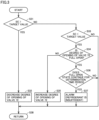
- Fig. 3 is a flowchart for illustrating control of second expansion valve 72.
- controller 100 calculates subcool SC of the refrigerant at the outlet portion of condenser 20 based on temperature T1 and a pressure in condenser 20 (approximated by PH). Specifically, controller 100 calculates subcool SC by subtracting temperature T1 from the saturation temperature of the refrigerant corresponding to pressure PH. It should be noted that a conversion table for obtaining the saturation temperature of the refrigerant corresponding to each pressure is stored beforehand in memory 104 of controller 100. Then, controller 100 compares calculated subcool SC with a target value. This target value is 5 K (kelvin), for example.
- controller 100 decreases a degree of opening of second expansion valve 72 (S32). Thereby, the amount of the liquid refrigerant to be exhausted from receiver 73 decreases and the amount of the liquid refrigerant within receiver 73 increases, and thus the amount of the refrigerant circulating through the main refrigerant circuit decreases. Accordingly, temperature T1 of the refrigerant increases, and thus subcool SC decreases.
- step S34 controller 100 determines whether or not the degree of opening of second expansion valve 72 is full open.
- full open means that the degree of opening of second expansion valve 72 has an upper limit value.
- controller 100 increases the degree of opening of second expansion valve 72 (S35).
- S35 the degree of opening of second expansion valve 72
- the amount of the liquid refrigerant to be exhausted from receiver 73 increases and the amount of the liquid refrigerant stored in receiver 73 decreases, and thus the amount of the refrigerant circulating through the main refrigerant circuit increases. Accordingly, temperature T1 of the refrigerant decreases, and thus subcool SC increases.
- step S36 controller 100 determines whether or not the state where second expansion valve 72 is fully opened continues for a determination time period.
- controller 100 maintains the degree of opening of second expansion valve 72 in the state of full open.
- controller 100 causes a notification device 101 to output an alarm indicating that the refrigerant is insufficient.
- Notification device 101 is, for example, a display device such as a liquid crystal display, an alarm lamp, or the like, and may be a device that transmits an alarm signal to an external device via a communication line.
- controller 100 After performing the processing in any of steps S32, S35, and S37, controller 100 advances the processing to step S38. Further, when subcool SC of the refrigerant at the outlet of condenser 20 is equal to the target value (NO in S31 and NO in S33), controller 100 advances the processing to step S38 while maintaining the present degree of opening. In these cases, the processing is temporarily returned to a main routine, and then the processing in the flowchart of Fig. 3 is performed repeatedly at fixed time intervals.
- Fig. 4 is a graph showing the relation between a degree of progress of shortage of the refrigerant and the degrees of opening of the expansion valves of the outdoor unit when leak of the refrigerant occurs.
- the degree of shortage of the refrigerant increases as the degree of progress increases from D0 to D3.
- the degree of progress is D0 to D1
- the amount of the refrigerant is not insufficient yet, and the liquid refrigerant is present in receiver 73.
- the temperature of the discharged refrigerant from compressor 10 is controlled properly by increasing the degree of opening of second expansion valve 72 to full open.
- subcool SC of the refrigerant at the outlet portion of condenser 20 gradually decreases, and subcool SC is zero when the degree of progress is D1.
- the degree of progress is D1 to D2
- the temperature of the discharged refrigerant from compressor 10 is still controlled properly, although subcool SC of the refrigerant at the outlet portion of condenser 20 is zero.
- the amount of the liquid refrigerant in receiver 73 decreases, and the liquid refrigerant is not present in receiver 73 when the degree of progress is D2.
- the degree of opening of second expansion valve 72 is full open.
- both first expansion valve 71 and second expansion valve 72 are fully opened. Since second expansion valve 72 is fully opened at an earlier stage, the shortage of the refrigerant can be detected at an earlier stage when the shortage of the refrigerant is determined based on the degree of opening of second expansion valve 72. In the present embodiment, it is determined that the refrigerant is insufficient when a time period for which the degree of opening of second expansion valve 72 is full open reaches the determination time period. Accordingly, a user can be notified of the shortage of the refrigerant at an early stage.
- the first embodiment has described the case that uses the refrigerant for which subcool SC can be calculated from temperature T1 and pressure PH, that is, the refrigerant used with the pressure in the condenser being less than a critical pressure.
- the refrigerant used with the pressure in the condenser being less than a critical pressure.
- adoption of natural refrigerant having a low global warming potential has been considered, and refrigerant used with a pressure in the condenser being more than or equal to the critical pressure, such as CO 2 , may be adopted.
- a second embodiment will describe detection of shortage of refrigerant in a case where such refrigerant is adopted.
- Fig. 5 is an overall configuration diagram of a refrigeration cycle apparatus according to the second embodiment. It should be noted that Fig. 5 functionally shows the connection relation and the arrangement configuration of devices in the refrigeration cycle apparatus, and does not necessarily show an arrangement in a physical space.
- a refrigeration cycle apparatus 1A includes an outdoor unit 2A, load device 3, and pipes 84 and 88. Since load device 3 and pipes 84 and 88 are the same as those in the first embodiment, the description thereof will not be repeated.
- Outdoor unit 2A includes a temperature sensor 123 instead of pressure sensor 112, and a controller 100A instead of controller 100, in the configuration of outdoor unit 2 shown in Fig. 1 . Since other components of outdoor unit 2A are the same as those of outdoor unit 2, the description thereof will not be repeated.
- Temperature sensor 123 detects an outside air temperature TA, which is an ambient temperature of outdoor unit 2A, and outputs a detection value thereof to controller 100A.
- Controller 100A includes CPU 102, memory 104, input/output buffers (not shown) for inputting/outputting various signals, and the like.
- CPU 102 expands programs stored in the ROM onto the RAM or the like and executes the programs.
- the programs stored in the ROM are programs describing processing procedures of controller 100A. According to these programs, controller 100A performs control of the devices in outdoor unit 2A. This control can be processed not only by software but also by dedicated hardware (electronic circuitry).
- Controller 100A feedback-controls first expansion valve 71 such that temperature TH of the discharged refrigerant from compressor 10 matches a target temperature. Since the control of first expansion valve 71 is the same as the control in the first embodiment shown in Fig. 2 , the description thereof will not be repeated.
- controller 100A feedback-controls second expansion valve 72 such that temperature T1 of the refrigerant at the outlet of condenser 20 matches a target temperature, in order to ensure subcool SC of the refrigerant at the outlet of condenser 20.
- controller 100A feedback-controls second expansion valve 72 such that temperature T1 of the refrigerant at the outlet of condenser 20 matches a target temperature, in order to ensure subcool SC of the refrigerant at the outlet of condenser 20.
- detection of shortage of the refrigerant is also performed simultaneously.
- a device which cools the refrigerant such as CO 2 in a supercritical state will also be referred to as condenser 20.
- an amount of decrease from a reference temperature of the refrigerant in the supercritical state will also be referred to as a subcool.
- the reference temperature is set to TA+ ⁇ , where TA is the temperature of the outside air measured by temperature sensor 123, and the amount of decrease has a target value of 5 K (kelvin), for example.
- shortage of the refrigerant can be detected at an early stage by the processing of the flowchart shown in Fig. 3 , by calculating subcool SC as a difference between temperature TA+ ⁇ and temperature T1.
- the design pressure of the container of receiver 73 can be set to be lower than that of the high pressure portion, and cost reduction by thinning the container can also be achieved.
- the present invention relates to outdoor unit 2 of refrigeration cycle apparatus 1 and outdoor unit 2A of refrigeration cycle apparatus 1A, each outdoor unit being connectable to load device 3 including expansion valve 50, which is an expansion device, and evaporator 60.
- Outdoor unit 2 shown in Fig. 1 and outdoor unit 2A shown in Fig. 5 include refrigerant outlet port PO2 and refrigerant inlet port PI2 for connecting to load device 3, first flow path F1, compressor 10, condenser 20, second flow path F2, first expansion valve 71, receiver 73, second expansion valve 72, and controller 100 or 100A.
- First flow path F1 which is a flow path from refrigerant inlet port PI2 to refrigerant outlet port PO2, is configured to form, together with load device 3, a circulation flow path through which refrigerant circulates.
- Compressor 10 and condenser 20 are disposed on first flow path F1 in order from refrigerant inlet port PI2 toward refrigerant outlet port PO2.
- Second flow path F2 is configured to branch from a portion of first flow path F1 between condenser 20 and refrigerant outlet port PO2, and to return, to compressor 10, the refrigerant that has passed through condenser 20.
- First expansion valve 71, receiver 73, and second expansion valve 72 are disposed on second flow path F2 in order from a branch point where second flow path F2 is branched from first flow path F1.
- Controllers 100 and 100A are configured to control compressor 10 and first and second expansion valves 71 and 72.
- Controllers 100 and 100A are configured to notify that the refrigerant is insufficient when a time period for which a degree of opening of second expansion valve 72 is at an upper limit exceeds a determination time period.
- the shortage of the refrigerant can be detected at an early stage in the configuration in which receiver 73 is disposed on the injection flow path, and degradation in the capability of the refrigeration cycle apparatus and continued leak of the refrigerant can be prevented.
- outdoor unit 2 shown in Fig. 1 further includes pressure sensor 111 configured to detect pressure PH of the refrigerant at the refrigerant outlet portion of condenser 20 on first flow path F1.
- pressure sensor 111 configured to detect pressure PH of the refrigerant at the refrigerant outlet portion of condenser 20 on first flow path F1.
- the refrigerant used in the configuration shown in Fig. 1 is refrigerant used with a pressure in condenser 20 being less than a critical pressure.
- outdoor unit 2A shown in Fig. 5 further includes second temperature sensor 123 configured to detect temperature TA of outside air to be supplied to condenser 20.
- second temperature sensor 123 configured to detect temperature TA of outside air to be supplied to condenser 20.
- the refrigerant used in the configuration shown in Fig. 5 is carbon dioxide used with a pressure in condenser 20 being more than or equal to the critical pressure.
- the present invention relates to a refrigeration cycle apparatus including the outdoor unit according to any one of the above descriptions, and the load device.
- 1, 1A refrigeration cycle apparatus
- 2, 2A outdoor unit
- 3 load device
- 10 compressor
- 20 condenser
- 22 fan
- 50 expansion valve
- 60 evaporator
- 70 flow rate limiting device
- 71 first expansion valve
- 72 second expansion valve
- 73 receiver
- 80, 81, 84, 85, 88, 89, 91, 92, 93, 94 pipe
- 100, 100A controller
- 101 notification device
- 104 memory
- 110, 111, 112 pressure sensor
- 120, 121, 123 temperature sensor
- F1, F2 flow path
- G1 suction port
- G2 discharge port
- G3 intermediate pressure port
- PI2, PI3 refrigerant inlet port
- PO2, PO3 refrigerant outlet port.
Landscapes
- Engineering & Computer Science (AREA)
- Physics & Mathematics (AREA)
- Mechanical Engineering (AREA)
- Thermal Sciences (AREA)
- General Engineering & Computer Science (AREA)
- Air Conditioning Control Device (AREA)
- Other Air-Conditioning Systems (AREA)
- Devices That Are Associated With Refrigeration Equipment (AREA)
Applications Claiming Priority (1)
| Application Number | Priority Date | Filing Date | Title |
|---|---|---|---|
| PCT/JP2019/035407 WO2021048905A1 (ja) | 2019-09-09 | 2019-09-09 | 室外ユニットおよび冷凍サイクル装置 |
Publications (3)
| Publication Number | Publication Date |
|---|---|
| EP4030122A1 EP4030122A1 (en) | 2022-07-20 |
| EP4030122A4 EP4030122A4 (en) | 2022-09-21 |
| EP4030122B1 true EP4030122B1 (en) | 2023-06-21 |
Family
ID=74866239
Family Applications (1)
| Application Number | Title | Priority Date | Filing Date |
|---|---|---|---|
| EP19944933.1A Active EP4030122B1 (en) | 2019-09-09 | 2019-09-09 | Outdoor unit and refrigeration cycle apparatus |
Country Status (7)
| Country | Link |
|---|---|
| EP (1) | EP4030122B1 (ja) |
| JP (1) | JP7199554B2 (ja) |
| CN (1) | CN114364934B (ja) |
| DK (1) | DK4030122T3 (ja) |
| ES (1) | ES2950759T3 (ja) |
| FI (1) | FI4030122T3 (ja) |
| WO (1) | WO2021048905A1 (ja) |
Families Citing this family (1)
| Publication number | Priority date | Publication date | Assignee | Title |
|---|---|---|---|---|
| JP2024043621A (ja) * | 2022-09-20 | 2024-04-02 | ダイキン工業株式会社 | 熱源ユニット、および冷凍装置 |
Family Cites Families (12)
| Publication number | Priority date | Publication date | Assignee | Title |
|---|---|---|---|---|
| JP3291753B2 (ja) * | 1992-04-08 | 2002-06-10 | ダイキン工業株式会社 | 冷凍装置の冷媒充填量検知装置 |
| JP4569708B2 (ja) * | 2008-12-05 | 2010-10-27 | ダイキン工業株式会社 | 冷凍装置 |
| JP5411643B2 (ja) * | 2009-10-05 | 2014-02-12 | パナソニック株式会社 | 冷凍サイクル装置および温水暖房装置 |
| JP5334909B2 (ja) * | 2010-04-20 | 2013-11-06 | 三菱電機株式会社 | 冷凍空調装置並びに冷凍空調システム |
| JP5623366B2 (ja) * | 2011-10-13 | 2014-11-12 | 福島工業株式会社 | 冷媒漏れ検知方法および冷凍冷蔵設備 |
| JP5927553B2 (ja) * | 2012-02-13 | 2016-06-01 | パナソニックIpマネジメント株式会社 | 冷凍装置 |
| JP5886463B1 (ja) * | 2015-08-07 | 2016-03-16 | 伸和コントロールズ株式会社 | 空気調和装置及びその運転方法 |
| JP2017053566A (ja) * | 2015-09-10 | 2017-03-16 | ジョンソンコントロールズ ヒタチ エア コンディショニング テクノロジー(ホンコン)リミテッド | 冷凍サイクル装置 |
| WO2017199391A1 (ja) * | 2016-05-19 | 2017-11-23 | 三菱電機株式会社 | 冷凍装置 |
| US11384965B2 (en) * | 2017-04-04 | 2022-07-12 | Mitsubishi Electric Corporation | Refrigeration cycle apparatus performing a refrigerant circulation operation using a liquid pump |
| KR102354891B1 (ko) * | 2017-05-31 | 2022-01-25 | 삼성전자주식회사 | 공기 조화기 및 그 제어 방법 |
| CN107940826B (zh) * | 2017-11-10 | 2020-04-03 | 广东美的暖通设备有限公司 | 多联机系统及其冷媒分配控制方法和装置 |
-
2019
- 2019-09-09 JP JP2021544993A patent/JP7199554B2/ja active Active
- 2019-09-09 WO PCT/JP2019/035407 patent/WO2021048905A1/ja unknown
- 2019-09-09 CN CN201980099971.7A patent/CN114364934B/zh active Active
- 2019-09-09 DK DK19944933.1T patent/DK4030122T3/da active
- 2019-09-09 EP EP19944933.1A patent/EP4030122B1/en active Active
- 2019-09-09 ES ES19944933T patent/ES2950759T3/es active Active
- 2019-09-09 FI FIEP19944933.1T patent/FI4030122T3/fi active
Also Published As
| Publication number | Publication date |
|---|---|
| FI4030122T3 (fi) | 2023-07-28 |
| JPWO2021048905A1 (ja) | 2021-03-18 |
| CN114364934A (zh) | 2022-04-15 |
| EP4030122A1 (en) | 2022-07-20 |
| CN114364934B (zh) | 2023-03-21 |
| DK4030122T3 (da) | 2023-07-24 |
| WO2021048905A1 (ja) | 2021-03-18 |
| JP7199554B2 (ja) | 2023-01-05 |
| EP4030122A4 (en) | 2022-09-21 |
| ES2950759T3 (es) | 2023-10-13 |
Similar Documents
| Publication | Publication Date | Title |
|---|---|---|
| US11131490B2 (en) | Refrigeration device having condenser unit connected to compressor unit with on-site pipe interposed therebetween and remote from the compressor unit | |
| EP2232169B1 (en) | Vapor compression system | |
| EP3954947B1 (en) | Outdoor unit, refrigeration cycle device, and refrigerating machine | |
| EP2693137A1 (en) | Device for estimating flowrate of heating medium, heat source device, and method for estimating flowrate of heating medium | |
| US10180269B2 (en) | Refrigeration device | |
| EP4030116B1 (en) | Outdoor unit and refrigeration cycle device | |
| EP4030122B1 (en) | Outdoor unit and refrigeration cycle apparatus | |
| JP6588626B2 (ja) | 冷凍装置 | |
| CN109579332B (zh) | 制冷系统 | |
| CN111148949B (zh) | 冷冻装置 | |
| US11959672B2 (en) | Air-conditioning apparatus | |
| JP4910725B2 (ja) | 冷却装置 | |
| EP4030117B1 (en) | Outdoor unit and refrigeration cycle device | |
| US20220146165A1 (en) | Air conditioning apparatus | |
| EP3499147A1 (en) | Refrigeration device, refrigeration system | |
| EP4130615A1 (en) | Outdoor unit and refrigeration cycle device | |
| JP7150191B2 (ja) | 室外ユニットおよび冷凍サイクル装置 | |
| GB2602893A (en) | Outdoor unit and refrigeration cycle device | |
| EP4071425A1 (en) | Outdoor unit and refrigeration cycle device | |
| JP7342269B2 (ja) | 冷熱源ユニット、および冷凍サイクル装置 | |
| EP3988871A1 (en) | Outdoor unit, refrigeration cycle device, and refrigerator | |
| US20210318046A1 (en) | Refrigeration cycle device | |
| JP2019207103A (ja) | 冷凍装置 |
Legal Events
| Date | Code | Title | Description |
|---|---|---|---|
| STAA | Information on the status of an ep patent application or granted ep patent |
Free format text: STATUS: THE INTERNATIONAL PUBLICATION HAS BEEN MADE |
|
| PUAI | Public reference made under article 153(3) epc to a published international application that has entered the european phase |
Free format text: ORIGINAL CODE: 0009012 |
|
| STAA | Information on the status of an ep patent application or granted ep patent |
Free format text: STATUS: REQUEST FOR EXAMINATION WAS MADE |
|
| 17P | Request for examination filed |
Effective date: 20220228 |
|
| AK | Designated contracting states |
Kind code of ref document: A1 Designated state(s): AL AT BE BG CH CY CZ DE DK EE ES FI FR GB GR HR HU IE IS IT LI LT LU LV MC MK MT NL NO PL PT RO RS SE SI SK SM TR |
|
| A4 | Supplementary search report drawn up and despatched |
Effective date: 20220823 |
|
| RIC1 | Information provided on ipc code assigned before grant |
Ipc: F25B 1/10 20060101ALI20220817BHEP Ipc: F25B 41/30 20210101ALI20220817BHEP Ipc: F25B 49/00 20060101ALI20220817BHEP Ipc: F25B 1/00 20060101ALI20220817BHEP Ipc: F25B 49/02 20060101AFI20220817BHEP |
|
| DAV | Request for validation of the european patent (deleted) | ||
| DAX | Request for extension of the european patent (deleted) | ||
| GRAP | Despatch of communication of intention to grant a patent |
Free format text: ORIGINAL CODE: EPIDOSNIGR1 |
|
| STAA | Information on the status of an ep patent application or granted ep patent |
Free format text: STATUS: GRANT OF PATENT IS INTENDED |
|
| RIC1 | Information provided on ipc code assigned before grant |
Ipc: F25B 1/10 20060101ALI20230203BHEP Ipc: F25B 41/30 20210101ALI20230203BHEP Ipc: F25B 49/00 20060101ALI20230203BHEP Ipc: F25B 1/00 20060101ALI20230203BHEP Ipc: F25B 49/02 20060101AFI20230203BHEP |
|
| INTG | Intention to grant announced |
Effective date: 20230307 |
|
| GRAS | Grant fee paid |
Free format text: ORIGINAL CODE: EPIDOSNIGR3 |
|
| GRAA | (expected) grant |
Free format text: ORIGINAL CODE: 0009210 |
|
| STAA | Information on the status of an ep patent application or granted ep patent |
Free format text: STATUS: THE PATENT HAS BEEN GRANTED |
|
| AK | Designated contracting states |
Kind code of ref document: B1 Designated state(s): AL AT BE BG CH CY CZ DE DK EE ES FI FR GB GR HR HU IE IS IT LI LT LU LV MC MK MT NL NO PL PT RO RS SE SI SK SM TR |
|
| P01 | Opt-out of the competence of the unified patent court (upc) registered |
Effective date: 20230512 |
|
| REG | Reference to a national code |
Ref country code: CH Ref legal event code: EP |
|
| REG | Reference to a national code |
Ref country code: DE Ref legal event code: R096 Ref document number: 602019031534 Country of ref document: DE |
|
| REG | Reference to a national code |
Ref country code: AT Ref legal event code: REF Ref document number: 1581146 Country of ref document: AT Kind code of ref document: T Effective date: 20230715 |
|
| REG | Reference to a national code |
Ref country code: IE Ref legal event code: FG4D |
|
| REG | Reference to a national code |
Ref country code: DK Ref legal event code: T3 Effective date: 20230719 |
|
| REG | Reference to a national code |
Ref country code: NO Ref legal event code: T2 Effective date: 20230621 |
|
| REG | Reference to a national code |
Ref country code: SE Ref legal event code: TRGR |
|
| REG | Reference to a national code |
Ref country code: LT Ref legal event code: MG9D |
|
| REG | Reference to a national code |
Ref country code: ES Ref legal event code: FG2A Ref document number: 2950759 Country of ref document: ES Kind code of ref document: T3 Effective date: 20231013 |
|
| REG | Reference to a national code |
Ref country code: NL Ref legal event code: MP Effective date: 20230621 |
|
| PGFP | Annual fee paid to national office [announced via postgrant information from national office to epo] |
Ref country code: NO Payment date: 20230911 Year of fee payment: 5 Ref country code: IT Payment date: 20230830 Year of fee payment: 5 Ref country code: GB Payment date: 20230824 Year of fee payment: 5 Ref country code: FI Payment date: 20230912 Year of fee payment: 5 |
|
| REG | Reference to a national code |
Ref country code: AT Ref legal event code: MK05 Ref document number: 1581146 Country of ref document: AT Kind code of ref document: T Effective date: 20230621 |
|
| PG25 | Lapsed in a contracting state [announced via postgrant information from national office to epo] |
Ref country code: RS Free format text: LAPSE BECAUSE OF FAILURE TO SUBMIT A TRANSLATION OF THE DESCRIPTION OR TO PAY THE FEE WITHIN THE PRESCRIBED TIME-LIMIT Effective date: 20230621 Ref country code: NL Free format text: LAPSE BECAUSE OF FAILURE TO SUBMIT A TRANSLATION OF THE DESCRIPTION OR TO PAY THE FEE WITHIN THE PRESCRIBED TIME-LIMIT Effective date: 20230621 Ref country code: LV Free format text: LAPSE BECAUSE OF FAILURE TO SUBMIT A TRANSLATION OF THE DESCRIPTION OR TO PAY THE FEE WITHIN THE PRESCRIBED TIME-LIMIT Effective date: 20230621 Ref country code: LT Free format text: LAPSE BECAUSE OF FAILURE TO SUBMIT A TRANSLATION OF THE DESCRIPTION OR TO PAY THE FEE WITHIN THE PRESCRIBED TIME-LIMIT Effective date: 20230621 Ref country code: HR Free format text: LAPSE BECAUSE OF FAILURE TO SUBMIT A TRANSLATION OF THE DESCRIPTION OR TO PAY THE FEE WITHIN THE PRESCRIBED TIME-LIMIT Effective date: 20230621 Ref country code: GR Free format text: LAPSE BECAUSE OF FAILURE TO SUBMIT A TRANSLATION OF THE DESCRIPTION OR TO PAY THE FEE WITHIN THE PRESCRIBED TIME-LIMIT Effective date: 20230922 |
|
| PGFP | Annual fee paid to national office [announced via postgrant information from national office to epo] |
Ref country code: SE Payment date: 20230830 Year of fee payment: 5 Ref country code: FR Payment date: 20230911 Year of fee payment: 5 Ref country code: DE Payment date: 20230822 Year of fee payment: 5 Ref country code: DK Payment date: 20230914 Year of fee payment: 5 |
|
| PG25 | Lapsed in a contracting state [announced via postgrant information from national office to epo] |
Ref country code: SK Free format text: LAPSE BECAUSE OF FAILURE TO SUBMIT A TRANSLATION OF THE DESCRIPTION OR TO PAY THE FEE WITHIN THE PRESCRIBED TIME-LIMIT Effective date: 20230621 |
|
| PGFP | Annual fee paid to national office [announced via postgrant information from national office to epo] |
Ref country code: ES Payment date: 20231003 Year of fee payment: 5 |
|
| PG25 | Lapsed in a contracting state [announced via postgrant information from national office to epo] |
Ref country code: IS Free format text: LAPSE BECAUSE OF FAILURE TO SUBMIT A TRANSLATION OF THE DESCRIPTION OR TO PAY THE FEE WITHIN THE PRESCRIBED TIME-LIMIT Effective date: 20231021 |
|
| PG25 | Lapsed in a contracting state [announced via postgrant information from national office to epo] |
Ref country code: SM Free format text: LAPSE BECAUSE OF FAILURE TO SUBMIT A TRANSLATION OF THE DESCRIPTION OR TO PAY THE FEE WITHIN THE PRESCRIBED TIME-LIMIT Effective date: 20230621 Ref country code: SK Free format text: LAPSE BECAUSE OF FAILURE TO SUBMIT A TRANSLATION OF THE DESCRIPTION OR TO PAY THE FEE WITHIN THE PRESCRIBED TIME-LIMIT Effective date: 20230621 Ref country code: RO Free format text: LAPSE BECAUSE OF FAILURE TO SUBMIT A TRANSLATION OF THE DESCRIPTION OR TO PAY THE FEE WITHIN THE PRESCRIBED TIME-LIMIT Effective date: 20230621 Ref country code: PT Free format text: LAPSE BECAUSE OF FAILURE TO SUBMIT A TRANSLATION OF THE DESCRIPTION OR TO PAY THE FEE WITHIN THE PRESCRIBED TIME-LIMIT Effective date: 20231023 Ref country code: IS Free format text: LAPSE BECAUSE OF FAILURE TO SUBMIT A TRANSLATION OF THE DESCRIPTION OR TO PAY THE FEE WITHIN THE PRESCRIBED TIME-LIMIT Effective date: 20231021 Ref country code: EE Free format text: LAPSE BECAUSE OF FAILURE TO SUBMIT A TRANSLATION OF THE DESCRIPTION OR TO PAY THE FEE WITHIN THE PRESCRIBED TIME-LIMIT Effective date: 20230621 Ref country code: CZ Free format text: LAPSE BECAUSE OF FAILURE TO SUBMIT A TRANSLATION OF THE DESCRIPTION OR TO PAY THE FEE WITHIN THE PRESCRIBED TIME-LIMIT Effective date: 20230621 Ref country code: AT Free format text: LAPSE BECAUSE OF FAILURE TO SUBMIT A TRANSLATION OF THE DESCRIPTION OR TO PAY THE FEE WITHIN THE PRESCRIBED TIME-LIMIT Effective date: 20230621 |
|
| PG25 | Lapsed in a contracting state [announced via postgrant information from national office to epo] |
Ref country code: PL Free format text: LAPSE BECAUSE OF FAILURE TO SUBMIT A TRANSLATION OF THE DESCRIPTION OR TO PAY THE FEE WITHIN THE PRESCRIBED TIME-LIMIT Effective date: 20230621 |
|
| REG | Reference to a national code |
Ref country code: DE Ref legal event code: R097 Ref document number: 602019031534 Country of ref document: DE |
|
| PLBE | No opposition filed within time limit |
Free format text: ORIGINAL CODE: 0009261 |
|
| STAA | Information on the status of an ep patent application or granted ep patent |
Free format text: STATUS: NO OPPOSITION FILED WITHIN TIME LIMIT |
|
| REG | Reference to a national code |
Ref country code: CH Ref legal event code: PL |
|
| PG25 | Lapsed in a contracting state [announced via postgrant information from national office to epo] |
Ref country code: SI Free format text: LAPSE BECAUSE OF FAILURE TO SUBMIT A TRANSLATION OF THE DESCRIPTION OR TO PAY THE FEE WITHIN THE PRESCRIBED TIME-LIMIT Effective date: 20230621 |
|
| PG25 | Lapsed in a contracting state [announced via postgrant information from national office to epo] |
Ref country code: LU Free format text: LAPSE BECAUSE OF NON-PAYMENT OF DUE FEES Effective date: 20230909 |
|
| 26N | No opposition filed |
Effective date: 20240322 |