EP4029671B1 - Verfahren zur herstellung eines harzbehälters und vorrichtung zur herstellung eines harzbehälters - Google Patents
Verfahren zur herstellung eines harzbehälters und vorrichtung zur herstellung eines harzbehälters Download PDFInfo
- Publication number
- EP4029671B1 EP4029671B1 EP20864178.7A EP20864178A EP4029671B1 EP 4029671 B1 EP4029671 B1 EP 4029671B1 EP 20864178 A EP20864178 A EP 20864178A EP 4029671 B1 EP4029671 B1 EP 4029671B1
- Authority
- EP
- European Patent Office
- Prior art keywords
- preform
- temperature
- temperature adjustment
- injection
- blow
- Prior art date
- Legal status (The legal status is an assumption and is not a legal conclusion. Google has not performed a legal analysis and makes no representation as to the accuracy of the status listed.)
- Active
Links
Images


Classifications
-
- B—PERFORMING OPERATIONS; TRANSPORTING
- B29—WORKING OF PLASTICS; WORKING OF SUBSTANCES IN A PLASTIC STATE IN GENERAL
- B29C—SHAPING OR JOINING OF PLASTICS; SHAPING OF MATERIAL IN A PLASTIC STATE, NOT OTHERWISE PROVIDED FOR; AFTER-TREATMENT OF THE SHAPED PRODUCTS, e.g. REPAIRING
- B29C49/00—Blow-moulding, i.e. blowing a preform or parison to a desired shape within a mould; Apparatus therefor
- B29C49/02—Combined blow-moulding and manufacture of the preform or the parison
- B29C49/06—Injection blow-moulding
- B29C49/061—Injection blow-moulding with parison holding means displaceable between injection and blow stations
- B29C49/062—Injection blow-moulding with parison holding means displaceable between injection and blow stations following an arcuate path, e.g. rotary or oscillating-type
-
- B—PERFORMING OPERATIONS; TRANSPORTING
- B29—WORKING OF PLASTICS; WORKING OF SUBSTANCES IN A PLASTIC STATE IN GENERAL
- B29B—PREPARATION OR PRETREATMENT OF THE MATERIAL TO BE SHAPED; MAKING GRANULES OR PREFORMS; RECOVERY OF PLASTICS OR OTHER CONSTITUENTS OF WASTE MATERIAL CONTAINING PLASTICS
- B29B11/00—Making preforms
- B29B11/06—Making preforms by moulding the material
- B29B11/08—Injection moulding
-
- B—PERFORMING OPERATIONS; TRANSPORTING
- B29—WORKING OF PLASTICS; WORKING OF SUBSTANCES IN A PLASTIC STATE IN GENERAL
- B29C—SHAPING OR JOINING OF PLASTICS; SHAPING OF MATERIAL IN A PLASTIC STATE, NOT OTHERWISE PROVIDED FOR; AFTER-TREATMENT OF THE SHAPED PRODUCTS, e.g. REPAIRING
- B29C45/00—Injection moulding, i.e. forcing the required volume of moulding material through a nozzle into a closed mould; Apparatus therefor
- B29C45/0053—Injection moulding, i.e. forcing the required volume of moulding material through a nozzle into a closed mould; Apparatus therefor combined with a final operation, e.g. shaping
-
- B—PERFORMING OPERATIONS; TRANSPORTING
- B29—WORKING OF PLASTICS; WORKING OF SUBSTANCES IN A PLASTIC STATE IN GENERAL
- B29C—SHAPING OR JOINING OF PLASTICS; SHAPING OF MATERIAL IN A PLASTIC STATE, NOT OTHERWISE PROVIDED FOR; AFTER-TREATMENT OF THE SHAPED PRODUCTS, e.g. REPAIRING
- B29C49/00—Blow-moulding, i.e. blowing a preform or parison to a desired shape within a mould; Apparatus therefor
- B29C49/02—Combined blow-moulding and manufacture of the preform or the parison
- B29C49/06—Injection blow-moulding
- B29C49/061—Injection blow-moulding with parison holding means displaceable between injection and blow stations
- B29C49/064—Injection blow-moulding with parison holding means displaceable between injection and blow stations following a rectilinear path, e.g. shuttle-type
-
- B—PERFORMING OPERATIONS; TRANSPORTING
- B29—WORKING OF PLASTICS; WORKING OF SUBSTANCES IN A PLASTIC STATE IN GENERAL
- B29C—SHAPING OR JOINING OF PLASTICS; SHAPING OF MATERIAL IN A PLASTIC STATE, NOT OTHERWISE PROVIDED FOR; AFTER-TREATMENT OF THE SHAPED PRODUCTS, e.g. REPAIRING
- B29C49/00—Blow-moulding, i.e. blowing a preform or parison to a desired shape within a mould; Apparatus therefor
- B29C49/28—Blow-moulding apparatus
- B29C49/30—Blow-moulding apparatus having movable moulds or mould parts
- B29C49/36—Blow-moulding apparatus having movable moulds or mould parts rotatable about one axis
-
- B—PERFORMING OPERATIONS; TRANSPORTING
- B29—WORKING OF PLASTICS; WORKING OF SUBSTANCES IN A PLASTIC STATE IN GENERAL
- B29C—SHAPING OR JOINING OF PLASTICS; SHAPING OF MATERIAL IN A PLASTIC STATE, NOT OTHERWISE PROVIDED FOR; AFTER-TREATMENT OF THE SHAPED PRODUCTS, e.g. REPAIRING
- B29C49/00—Blow-moulding, i.e. blowing a preform or parison to a desired shape within a mould; Apparatus therefor
- B29C49/42—Component parts, details or accessories; Auxiliary operations
- B29C49/4205—Handling means, e.g. transfer, loading or discharging means
- B29C49/42113—Means for manipulating the objects' position or orientation
-
- B—PERFORMING OPERATIONS; TRANSPORTING
- B29—WORKING OF PLASTICS; WORKING OF SUBSTANCES IN A PLASTIC STATE IN GENERAL
- B29C—SHAPING OR JOINING OF PLASTICS; SHAPING OF MATERIAL IN A PLASTIC STATE, NOT OTHERWISE PROVIDED FOR; AFTER-TREATMENT OF THE SHAPED PRODUCTS, e.g. REPAIRING
- B29C49/00—Blow-moulding, i.e. blowing a preform or parison to a desired shape within a mould; Apparatus therefor
- B29C49/42—Component parts, details or accessories; Auxiliary operations
- B29C49/64—Heating or cooling preforms, parisons or blown articles
- B29C49/6409—Thermal conditioning of preforms
- B29C49/6418—Heating of preforms
-
- B—PERFORMING OPERATIONS; TRANSPORTING
- B29—WORKING OF PLASTICS; WORKING OF SUBSTANCES IN A PLASTIC STATE IN GENERAL
- B29C—SHAPING OR JOINING OF PLASTICS; SHAPING OF MATERIAL IN A PLASTIC STATE, NOT OTHERWISE PROVIDED FOR; AFTER-TREATMENT OF THE SHAPED PRODUCTS, e.g. REPAIRING
- B29C49/00—Blow-moulding, i.e. blowing a preform or parison to a desired shape within a mould; Apparatus therefor
- B29C49/42—Component parts, details or accessories; Auxiliary operations
- B29C49/64—Heating or cooling preforms, parisons or blown articles
- B29C49/6409—Thermal conditioning of preforms
- B29C49/6427—Cooling of preforms
-
- B—PERFORMING OPERATIONS; TRANSPORTING
- B29—WORKING OF PLASTICS; WORKING OF SUBSTANCES IN A PLASTIC STATE IN GENERAL
- B29C—SHAPING OR JOINING OF PLASTICS; SHAPING OF MATERIAL IN A PLASTIC STATE, NOT OTHERWISE PROVIDED FOR; AFTER-TREATMENT OF THE SHAPED PRODUCTS, e.g. REPAIRING
- B29C49/00—Blow-moulding, i.e. blowing a preform or parison to a desired shape within a mould; Apparatus therefor
- B29C49/42—Component parts, details or accessories; Auxiliary operations
- B29C49/64—Heating or cooling preforms, parisons or blown articles
- B29C49/6409—Thermal conditioning of preforms
- B29C49/6463—Thermal conditioning of preforms by contact heating or cooling, e.g. mandrels or cores specially adapted for heating or cooling preforms
- B29C49/6464—Heating
-
- B—PERFORMING OPERATIONS; TRANSPORTING
- B29—WORKING OF PLASTICS; WORKING OF SUBSTANCES IN A PLASTIC STATE IN GENERAL
- B29C—SHAPING OR JOINING OF PLASTICS; SHAPING OF MATERIAL IN A PLASTIC STATE, NOT OTHERWISE PROVIDED FOR; AFTER-TREATMENT OF THE SHAPED PRODUCTS, e.g. REPAIRING
- B29C49/00—Blow-moulding, i.e. blowing a preform or parison to a desired shape within a mould; Apparatus therefor
- B29C49/42—Component parts, details or accessories; Auxiliary operations
- B29C49/64—Heating or cooling preforms, parisons or blown articles
- B29C49/6409—Thermal conditioning of preforms
- B29C49/6463—Thermal conditioning of preforms by contact heating or cooling, e.g. mandrels or cores specially adapted for heating or cooling preforms
- B29C49/6465—Cooling
-
- B—PERFORMING OPERATIONS; TRANSPORTING
- B29—WORKING OF PLASTICS; WORKING OF SUBSTANCES IN A PLASTIC STATE IN GENERAL
- B29C—SHAPING OR JOINING OF PLASTICS; SHAPING OF MATERIAL IN A PLASTIC STATE, NOT OTHERWISE PROVIDED FOR; AFTER-TREATMENT OF THE SHAPED PRODUCTS, e.g. REPAIRING
- B29C49/00—Blow-moulding, i.e. blowing a preform or parison to a desired shape within a mould; Apparatus therefor
- B29C49/42—Component parts, details or accessories; Auxiliary operations
- B29C49/64—Heating or cooling preforms, parisons or blown articles
- B29C49/6472—Heating or cooling preforms, parisons or blown articles in several stages
- B29C49/648—Heating or cooling preforms, parisons or blown articles in several stages of preforms or parisons
-
- B—PERFORMING OPERATIONS; TRANSPORTING
- B29—WORKING OF PLASTICS; WORKING OF SUBSTANCES IN A PLASTIC STATE IN GENERAL
- B29C—SHAPING OR JOINING OF PLASTICS; SHAPING OF MATERIAL IN A PLASTIC STATE, NOT OTHERWISE PROVIDED FOR; AFTER-TREATMENT OF THE SHAPED PRODUCTS, e.g. REPAIRING
- B29C49/00—Blow-moulding, i.e. blowing a preform or parison to a desired shape within a mould; Apparatus therefor
- B29C49/42—Component parts, details or accessories; Auxiliary operations
- B29C49/78—Measuring, controlling or regulating
- B29C49/786—Temperature
-
- B—PERFORMING OPERATIONS; TRANSPORTING
- B29—WORKING OF PLASTICS; WORKING OF SUBSTANCES IN A PLASTIC STATE IN GENERAL
- B29C—SHAPING OR JOINING OF PLASTICS; SHAPING OF MATERIAL IN A PLASTIC STATE, NOT OTHERWISE PROVIDED FOR; AFTER-TREATMENT OF THE SHAPED PRODUCTS, e.g. REPAIRING
- B29C45/00—Injection moulding, i.e. forcing the required volume of moulding material through a nozzle into a closed mould; Apparatus therefor
- B29C45/17—Component parts, details or accessories; Auxiliary operations
- B29C45/72—Heating or cooling
- B29C45/7207—Heating or cooling of the moulded articles
- B29C2045/7214—Preform carriers for cooling preforms
- B29C2045/725—Cooling circuits within the preform carriers
-
- B—PERFORMING OPERATIONS; TRANSPORTING
- B29—WORKING OF PLASTICS; WORKING OF SUBSTANCES IN A PLASTIC STATE IN GENERAL
- B29C—SHAPING OR JOINING OF PLASTICS; SHAPING OF MATERIAL IN A PLASTIC STATE, NOT OTHERWISE PROVIDED FOR; AFTER-TREATMENT OF THE SHAPED PRODUCTS, e.g. REPAIRING
- B29C49/00—Blow-moulding, i.e. blowing a preform or parison to a desired shape within a mould; Apparatus therefor
- B29C49/02—Combined blow-moulding and manufacture of the preform or the parison
- B29C2049/023—Combined blow-moulding and manufacture of the preform or the parison using inherent heat of the preform, i.e. 1 step blow moulding
-
- B—PERFORMING OPERATIONS; TRANSPORTING
- B29—WORKING OF PLASTICS; WORKING OF SUBSTANCES IN A PLASTIC STATE IN GENERAL
- B29C—SHAPING OR JOINING OF PLASTICS; SHAPING OF MATERIAL IN A PLASTIC STATE, NOT OTHERWISE PROVIDED FOR; AFTER-TREATMENT OF THE SHAPED PRODUCTS, e.g. REPAIRING
- B29C2949/00—Indexing scheme relating to blow-moulding
- B29C2949/07—Preforms or parisons characterised by their configuration
- B29C2949/0715—Preforms or parisons characterised by their configuration the preform having one end closed
-
- B—PERFORMING OPERATIONS; TRANSPORTING
- B29—WORKING OF PLASTICS; WORKING OF SUBSTANCES IN A PLASTIC STATE IN GENERAL
- B29C—SHAPING OR JOINING OF PLASTICS; SHAPING OF MATERIAL IN A PLASTIC STATE, NOT OTHERWISE PROVIDED FOR; AFTER-TREATMENT OF THE SHAPED PRODUCTS, e.g. REPAIRING
- B29C49/00—Blow-moulding, i.e. blowing a preform or parison to a desired shape within a mould; Apparatus therefor
- B29C49/006—Blow-moulding plants, e.g. using several blow-moulding apparatuses cooperating
- B29C49/0062—Blow-moulding plants, e.g. using several blow-moulding apparatuses cooperating using two or more parallel stations, e.g. two parallel heating or blowing stations
- B29C49/0064—Blow-moulding plants, e.g. using several blow-moulding apparatuses cooperating using two or more parallel stations, e.g. two parallel heating or blowing stations the number of preform manufacturing stations being different to the number of blowing stations
-
- B—PERFORMING OPERATIONS; TRANSPORTING
- B29—WORKING OF PLASTICS; WORKING OF SUBSTANCES IN A PLASTIC STATE IN GENERAL
- B29C—SHAPING OR JOINING OF PLASTICS; SHAPING OF MATERIAL IN A PLASTIC STATE, NOT OTHERWISE PROVIDED FOR; AFTER-TREATMENT OF THE SHAPED PRODUCTS, e.g. REPAIRING
- B29C49/00—Blow-moulding, i.e. blowing a preform or parison to a desired shape within a mould; Apparatus therefor
- B29C49/42—Component parts, details or accessories; Auxiliary operations
- B29C49/4205—Handling means, e.g. transfer, loading or discharging means
- B29C49/42113—Means for manipulating the objects' position or orientation
- B29C49/42121—Changing the center-center distance
- B29C49/42122—Adapting to blow-mould cavity center-center distance
-
- B—PERFORMING OPERATIONS; TRANSPORTING
- B29—WORKING OF PLASTICS; WORKING OF SUBSTANCES IN A PLASTIC STATE IN GENERAL
- B29C—SHAPING OR JOINING OF PLASTICS; SHAPING OF MATERIAL IN A PLASTIC STATE, NOT OTHERWISE PROVIDED FOR; AFTER-TREATMENT OF THE SHAPED PRODUCTS, e.g. REPAIRING
- B29C49/00—Blow-moulding, i.e. blowing a preform or parison to a desired shape within a mould; Apparatus therefor
- B29C49/42—Component parts, details or accessories; Auxiliary operations
- B29C49/64—Heating or cooling preforms, parisons or blown articles
- B29C49/68—Ovens specially adapted for heating preforms or parisons
- B29C49/6845—Ovens specially adapted for heating preforms or parisons using ventilation, e.g. a fan
-
- B—PERFORMING OPERATIONS; TRANSPORTING
- B29—WORKING OF PLASTICS; WORKING OF SUBSTANCES IN A PLASTIC STATE IN GENERAL
- B29K—INDEXING SCHEME ASSOCIATED WITH SUBCLASSES B29B, B29C OR B29D, RELATING TO MOULDING MATERIALS OR TO MATERIALS FOR MOULDS, REINFORCEMENTS, FILLERS OR PREFORMED PARTS, e.g. INSERTS
- B29K2067/00—Use of polyesters or derivatives thereof, as moulding material
- B29K2067/003—PET, i.e. poylethylene terephthalate
-
- B—PERFORMING OPERATIONS; TRANSPORTING
- B29—WORKING OF PLASTICS; WORKING OF SUBSTANCES IN A PLASTIC STATE IN GENERAL
- B29L—INDEXING SCHEME ASSOCIATED WITH SUBCLASS B29C, RELATING TO PARTICULAR ARTICLES
- B29L2031/00—Other particular articles
- B29L2031/712—Containers; Packaging elements or accessories, Packages
- B29L2031/7158—Bottles
Definitions
- the present invention relates to a resin container manufacturing method and a resin container manufacturing apparatus.
- Patent Literature 1 describes a hot parison type blow molding apparatus and a resin container manufacturing method using the blow molding apparatus.
- Patent Literature 2 describes a large container obtained by blow molding a bottomed tubular preform, which is obtained by injection molding a polyester resin, after temperature adjustment.
- EP 3 418 027 B1 describes a device including an injection forming unit that produces a resin preform having a bottom; a blow forming unit; a support part that supports the preform; and a conveying unit that conveys the support part to the blow forming unit, wherein the blow forming unit further has a first mold unit for performing a first step in which the preform that was produced with the injection molding unit is subjected to heat-set blowing at a first temperature, a second mold unit for performing a second step in which an intermediate molded article that was blow molded through heat-set blowing is blow molded at a second temperature to produce a container, said second temperature being lower than the first temperature, and a movement unit that can move the first mold unit and the second mold unit relative to the support part in order to perform the first step and the second step continuously.
- US 2019/152121 A1 describes a blow molding machine including an injection molding unit and a blow molding unit, wherein the injection molding unit includes a preform mold and an injection device configured to supply resin to the preform mold, wherein the injection device is fixed to a support plate, and wherein the support plate includes a position adjustment mechanism capable of adjusting a position of the injection device in an upper and lower direction with respect to the preform mold.
- US 2018/304519 A1 describes a mold including a link member including a protruding grip forming part configured to form a grip part to a portion of a container by pressurizing a portion of a preform that is expanded during blow molding; and a piston member configured to move forward toward a cavity to thus press and rotate the link member.
- US 4 151 249 A describes a method of making blown plastic containers having internal ribs.
- the hot parison type blow molding apparatus if a method of injection molding a plurality of preforms along a predetermined arrangement direction and conveying the preforms in a direction intersecting the arrangement direction to blow mold containers is adopted, a number ratio of preforms can be changed between the injection molding part and the blow molding part, and thus, there are advantages such as downsizing of a blow molding mold and local cooling of the preforms during conveying.
- this method when the injection molded preforms are divided into blow molding units (divided into the number of blow cavities) and intermittently conveyed to the blow molding part, a length of waiting time until reaching the blow molding part changes for each unit, which tends to cause a temperature difference between the preforms.
- An object of the present invention is to provide a resin container manufacturing method and a resin container manufacturing apparatus that can stably manufacture high-quality containers by reducing a temperature condition difference between preforms even when a conveying method that tends to cause the temperature difference between preforms is adopted.
- Another object of the present invention is to provide a resin container manufacturing method and a resin container manufacturing apparatus that ensure a uniform temperature between preforms and can stably manufacture high-quality containers even when a conveying method that tends to cause a temperature difference between preforms is adopted.
- a resin container manufacturing method which can solve the above problem, includes:
- a resin container manufacturing apparatus which can solve the above problem, includes:
- a resin container manufacturing method which can solve the above problem, includes:
- the present invention can provide a resin container manufacturing method and a resin container manufacturing apparatus that can stably manufacture high-quality containers by reducing a temperature condition difference between preforms even when a conveying method that tends to cause the temperature difference between preforms is adopted.
- the present invention can also provide a resin container manufacturing method and a resin container manufacturing apparatus that ensure a uniform temperature between preforms and can stably manufacture high-quality containers even when a conveying method that tends to cause a temperature difference between preforms is adopted.
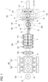
- Fig. 1 is a schematic diagram in a plan view illustrating a resin container manufacturing apparatus 1 according to the present embodiment.
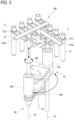
- Fig. 2 is a schematic diagram in a side view illustrating the resin container manufacturing apparatus 1 according to the present embodiment.
- the manufacturing apparatus 1 is a so-called 4-station type molding apparatus, including: an injection molding part 100 that injection molds a plurality of preforms 10 along a predetermined arrangement direction C; a temperature adjustment part 200 that adjusts a temperature of the preform 10; a blow molding part 300 that molds a resin container 20 from the preform 10; and a take-out part 400 that takes out the molded container 20.
- the container 20 manufactured by the manufacturing apparatus 1 can be a large bottle such as a 19 litres (5-gallon) bottle.
- the manufacturing apparatus is a one-step type that uses a divided blow method.
- the injection molding part 100, the temperature adjustment part 200, the blow molding part 300, and the take-out part 400 are arranged linearly.
- the manufacturing apparatus 1 includes conveying mechanisms 600 and 650 (not shown in Fig. 1 ) that convey the preform 10 and the container 20 along a conveying direction A intersecting the arrangement direction C over the temperature adjustment part 200 and the blow molding part 300.
- the manufacturing apparatus 1 is provided with a conversion part 150 between the injection molding part 100 and the temperature adjustment part 200.
- the conversion part 150 includes a conversion mechanism 500 that changes an alignment direction of the plurality of preforms 10 from the arrangement direction C to a direction along the conveying direction A.
- the injection molding part 100 injection molds the plurality of preforms 10 so that the plurality of preforms 10 are aligned along the arrangement direction C.
- the injection molding part 100 includes at least one first injection mold 110 and at least two second injection molds 120.
- the first injection mold 110 includes an injection cavity mold 112 provided with a plurality of (for example, four) recesses 114 that define outer shapes of a body portion and a bottom portion of the preform 10.
- the first injection mold 110 is connected to an injection device 102 that injects a resin material, which is a raw material of the preform 10 (for example, polyester such as polyethylene terephthalate (PET), polycarbonate (PC), and the like), and the plurality of (for example, four) recesses 114 are linearly aligned in the arrangement direction C orthogonal to an injection direction B of the injection device 102.
- the arrangement direction C also intersects (is orthogonal to) the conveying direction A.
- the injection device 102 is connected to a central portion of the first injection mold 110 in the arrangement direction C.
- a refrigerant is caused to flow through the first injection mold 110 and the second injection molds 120 of the injection molding part 100.
- a temperature of the refrigerant is set to, for example, 5°C to 20°C.
- the two second injection molds 120 each include four injection core molds 122 and injection neck molds (neck molds) 124, which are arranged along the arrangement direction C, respectively.
- the injection core molds 122 define inner shapes of a neck portion, the body portion, and the bottom portion of the preform 10, and the injection neck molds 124 define an outer shape of the neck portion.
- the two second injection molds 120 are connected to a first rotating member 130, which is a rotation plate, and are located on a circumference centered on a first central axis X1, and the two second injection molds 120 are configured to be intermittently rotatable with respect to the first central axis X1.
- the two second injection molds 120 are arranged at positions rotated by 180° from each other with respect to the first central axis X1.
- the first rotating member 130 is configured to intermittently rotate by 180° per cycle of the injection molding to swap the positions of the two second injection molds 120 with each other.
- One of the second injection molds 120 is arranged at a position where the first injection mold 110 is arranged (injection position P1), and the other one of the second injection molds 120 is arranged at a position rotated by 180° on an opposite side of the injection position P1 with respect to the first central axis X1 (post-cooling position P2).
- the post-cooling position P2 is a position where the preform 10 injection molded at the injection position P1 is held and cooled by the injection core molds 122 and the injection neck molds 124.
- the post-cooling position P2 is provided with a cooling pod 140 that can accommodate the preform 10 and can be raised and lowered.
- the cooling pod 140 is provided with a cavity 142 that accommodates the preform 10 and a flow path for a refrigerant such as water is provided around the cavity 142, and the cooling pod 140 is a member capable of cooling the preform 10 from outside.
- the cooling pod 140 is set to a temperature of, for example, 5°C to 60°C, and preferably 5°C to 20°C.
- the injection molding part 100 includes an injection part that is a part located at the injection position P1 and a post-cooling part that is a part located at the post-cooling position P2.
- the injection part injects molten resin into a cavity to mold the preform 10.
- the post-cooling part cools the preform 10 molded at the injection part and released from the cavity.
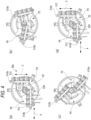
- Fig. 3 is a perspective view illustrating an outline of the conversion mechanism 500.
- the conversion mechanism 500 includes holding members 510a and 510b (for example, a hand member or a chuck member) configured to hold the preform 10, a second rotating member 520 which is a moving mechanism configured to move the holding members 510a and 510b, and two holding member conversion mechanisms 530 (for example, an electric motor) configured so that the holding members 510a and 510b can be changed in direction while the holding members 510a and 510b are moved.
- holding members 510a and 510b for example, a hand member or a chuck member
- a second rotating member 520 which is a moving mechanism configured to move the holding members 510a and 510b
- two holding member conversion mechanisms 530 for example, an electric motor
- a second cooling pod 140b constituted by a pair of split molds capable of accommodating the preform 10 may be provided at a sending position P4, which will be described later, of the conversion mechanism 500.
- the second cooling pod 140b is set to, for example, 5°C to 60°C, and is preferably set to a temperature higher than that of the first cooling pod 140.
- the holding members 510a and 510b include a holding part 512 (for example, a claw or a hand) that grips and holds a neck portion 12 of the preform 10.
- the holding members 510a and 510b are configured so that the preform can be moved up and down, that is, can be raised and lowered.
- the holding part 512 is configured to be slidable in a horizontal direction with respect to the holding member 510a (510b).
- the holding member 510a (510b) is configured to be able to move up and down with respect to the second rotating member 520.
- the second rotating member 520 is configured to be rotated by a rotating mechanism 540 (for example, an electric motor) around a second central axis X2.
- the second rotating member 520 is configured to move the holding members 510a and 510b from a receiving position P3 for receiving the plurality of injection-molded preforms 10 in the injection molding part 100 to a sending position P4 for sending the preforms 10 to the temperature adjustment part 200.
- the holding members 510a and 510b are supported by the second rotating member 520 at positions rotated by 180° from each other with respect to the second central axis X2 on the second rotating member 520.
- the two holding member conversion mechanisms 530 are provided on the second rotating member 520 so as to correspond to the holding members 510a and 510b, respectively.
- the post-cooling position P2 and the receiving position P3 are arranged so as to overlap each other in the vertical direction (up-down direction) of the manufacturing apparatus 1.
- a second post-cooling position and the sending position P4 which will be described later, may be arranged so as to overlap each other in the vertical direction (up-down direction) of the manufacturing apparatus 1.
- the holding member conversion mechanisms 530 are configured to change the alignment direction of the plurality of preforms 10 from the arrangement direction C to a direction along the conveying direction A by rotating the holding members 510a and 510b on their own axes while moving the holding members 510a and 5 10b. That is, the holding members 510a and 510b are configured to be capable of intermittently rotating (rotating on their own axes) by 90° around a third central axis X3 by the holding member conversion mechanisms 530.
- Fig. 4 is a diagram illustrating the operations of the conversion mechanism 500.
- the conversion mechanisms 500 in Figs. 3 and 4 do not always match with each other, they are common in the configurations described above, and the operation will be described with reference to Fig. 4 for convenience.
- (a) shows an initial state of the conversion mechanism 500
- (b) shows a primary state of the conversion mechanism 500
- (c) shows a secondary state of the conversion mechanism 500
- (d) shows a tertiary state of the conversion mechanism 500.
- the holding member 510a is arranged at the receiving position P3, and a plurality of holding parts 512 are arranged so as to be aligned in a direction along the arrangement direction C in the injection molding part 100.
- the holding member 510b is arranged at the sending position P4, and a plurality of holding parts 512 are arranged so as to be aligned in a direction along the conveying direction A.
- the conversion mechanism 500 transitions to the primary state shown in (b) of Fig. 4 and then the secondary state shown in (c) of Fig. 4 .
- the second rotating member 520 rotates clockwise, and the holding member 510a and the holding member 510b are exchanged in position.
- the holding member 510a rotates counterclockwise on its own axis
- the holding member 510b rotates clockwise on its own axis.
- the second rotating member 520 rotates 180° and stops.
- the holding member 510a and the holding member 510b rotate 90° in opposite directions and stop.
- the holding member 510a is arranged at the sending position P4, and the plurality of holding parts 512 are arranged so as to be aligned in a direction along the conveying direction A.
- the holding member 510b is arranged at the receiving position P3, and the plurality of holding parts 512 are arranged so as to be aligned in a direction along the arrangement direction C in the injection molding part 100.
- the second cooling pod 140b accommodates and holds the preform 10 at the sending position P4.
- the positions of the holding member 510a and the holding member 510b are exchanged from the tertiary state to the secondary state and then the primary state, by operations which are opposite to the above-mentioned operations. That is, the second rotating member 520 rotates counterclockwise, the holding member 510a rotates clockwise on its own axis, and the holding member 510b rotates counterclockwise on its own axis. In this way, the conversion mechanism 500 returns to the initial state.
- the holding member 510a and the holding member 510b are exchanged in position, and the preform 10 is transferred from the injection molding part 100 to the temperature adjustment part 200.
- the second rotating member 520 has a rotation mode of switching between clockwise and counterclockwise every time it rotates by 180°, but may also have a mode in which the direction of rotation is fixed clockwise or counterclockwise and the rotation is performed intermittently by 180°.
- one preform located at one end of the plurality of preforms along the arrangement direction C in the injection molding part 100 is defined as a first preform and one preform located at another end is defined as an N1st preform (N1 is an integer of 2 or more).
- N1 is an integer of 2 or more.
- the conversion mechanism 500 is configured to be capable of changing the alignment direction of the plurality of preforms 10 from the arrangement direction C to a direction along the conveying direction A, so that the first preform (or the N1st preform) is always at the front.
- the manufacturing apparatus 1 When the preform 10 is held by the conversion mechanism 500 between the injection molding part 100 and the temperature adjustment part 200, the preform is naturally cooled in the atmosphere.
- the manufacturing apparatus 1 includes a natural cooling part 700 between the injection molding part 100 and the temperature adjustment part 200.
- the above-mentioned conversion part 150 is provided in the natural cooling part 700.
- the term "natural cooling” used herein does not mean cooling to room temperature, but means natural cooling in the atmosphere.
- the conveying mechanisms 600 and 650 are separately provided.
- the conveying mechanism 600 is configured to receive the preform 10 arranged at the sending position P4 of the conversion mechanism 500 and convey the preform 10 to the temperature adjustment part 200.
- the conveying mechanism 650 is configured to receive the preform 10 conveyed to the temperature adjustment part 200 by the conveying mechanism 600, and convey the preform 10 and the container 20 along the conveying direction A over the temperature adjustment part 200, the blow molding part 300, and the take-out part 400.
- a translational movement chuck hand
- Conveying of the preform between the conversion mechanism 500 and the conveying mechanism 600 and between the conveying mechanism 600 and the conveying mechanism 650 can be carried out by means known in the art to which the present invention belongs, so detailed explanation thereof is omitted.
- the conveying by the conveying mechanisms 600 and 650 is performed intermittently.
- An interval (pitch) between the preforms 10 and the containers 20 can be changed on halfway.
- the conveying mechanism 600 is configured so that an interval (pitch) P1 of the injection molding part 100 can be converted to an interval P2 of the temperature adjustment part 200 (P1 ⁇ P2)
- the transfer mechanism 650 is configured so that the interval P2 of the temperature adjustment part 200 can be converted to an interval P3 of the blow molding part 300 (P2 ⁇ P3).
- the conveying mechanism 650 is configured to convert the number of the preforms 10 and the containers 20 to be conveyed by one intermittent conveying in the middle of a conveying path. Specifically, the conveying mechanism 650 is configured to intermittently convey two preforms to a heat retention temperature adjustment part 230 and a fine adjustment part 240, which will be described later, and thereafter intermittently convey the preform and the container one by one.
- the temperature adjustment part 200 includes a first temperature adjustment part 210 that adjusts the temperature of the preform, a second temperature adjustment part 220 that adjusts the temperature of the preform 10 under a condition different from that of the first temperature adjustment part 210, the heat retention temperature adjustment part 230 that prevents a temperature drop of the temperature-adjusted preform 10, and the fine adjustment part 240 that finely adjusts the temperature of the preform 10.
- a condition for adjusting the temperature of the preform 10 in the first temperature adjustment part 210 has a higher ability to lower the temperature of the preform 10 than a condition for adjusting the temperature of the preform 10 in the second temperature adjustment part 220.
- the "higher ability to lower the temperature” means that the preform 10 can be cooled more rapidly than a comparison target. More specifically, it means that a temperature range of the preform to be lowered per unit time is large.
- the temperature of the preform 10 may be adjusted from a state where an average temperature of the preforms 10 is 135°C to 160°C to a state where the average temperature is 120°C to 130°C, and in the second temperature adjustment part 220, the temperature of the preform 10 may be adjusted from a state where the average temperature of the preforms 10 is 120°C to 130°C to a state where the average temperature is 110°C to 120°C.
- the first temperature adjustment part 210 and the second temperature adjustment part 220 various temperature adjustment means, such as a method of sandwiching the preform between a temperature adjustment cavity mold and a temperature adjustment core mold (temperature adjustment rod mold), a method of blowing air onto the preform, various infrared heaters, a RED method, and an electromagnetic wave heating method, can be adopted.
- the first temperature adjustment part 210 includes a temperature adjustment core mold and a temperature adjustment cavity mold configured to adjust the temperature of the preform 10 by sandwiching the preform 10 therebetween
- the second temperature adjustment part 220 includes a temperature adjustment blow core mold that adjusts the temperature of the preform 10 by blowing a gas onto the preform 10 and optionally includes a temperature adjustment cavity mold that accommodates the preform 10.
- a preliminary blow may be performed in the second temperature adjustment part 220 to slightly inflate the preform 10 before conveying the preform 10 to the blow molding part 300.
- the first temperature adjustment part 210 may adopt a method for adjusting the temperature of the preform 10 from inside by convection by supplying and blowing gas to an inside of the preform 10 accommodated in the temperature adjustment cavity side by the temperature adjustment blow core mold, and continuously discharging the blown gas to an outside of the preform.
- the second temperature adjustment part 220 may adopt a method for preliminary blowing the preform 10 by supplying and blowing gas to the inside of the preform 10 accommodated in the temperature adjustment cavity side by the temperature adjustment blow core mold without discharging the gas to the outside of the preform 10 during blowing.
- the outside of the preform 10 may be brought into contact with the temperature adjustment cavity mold, and the temperature of the preform 10 may be adjusted from outside by heat conduction.
- a space (cavity) of the temperature adjustment cavity accommodating the preform 10 may be set larger in the second temperature adjustment part 210 than in the first temperature adjustment part 210.
- the first temperature adjustment part 210 and the second temperature adjustment part 220 are configured so that the temperature adjustment of two preforms can be performed respectively.
- a temperature adjustment medium (cooling medium) is flowed through the temperature adjustment cavity mold and the temperature adjustment core mold of the first temperature adjustment part 210 and the second temperature adjustment part 220.
- a temperature of the cooling medium is set to, for example, 40°C to 100°C, preferably 50°C to 70°C.
- the heat retention temperature adjustment part 230 is set to a temperature close to a blow optimum temperature at a uniform temperature as a whole so as to prevent the temperature of the preform 10 which has been temperature-adjusted to a temperature close to a temperature suitable for blow molding from dropping.
- various temperature adjustment methods such as various infrared heaters, a RED method, and an electromagnetic wave heating method can be adopted.
- the heat retention temperature adjustment part 230 is configured to be capable of adjusting the temperature of one preform (specifically, preventing a temperature drop of the preform).
- the fine adjustment part 240 finely adjusts the temperature of the preform 10 to a temperature suitable for blow molding.
- finely adjust means finely adjusting the temperature of the whole preform 10 to a temperature suitable for blow molding.
- finely adjust means, for example, that the temperature of the preform is intentionally made different for each part according to a shape of the container, or that the temperature unevenness for each part of the preform 10 is finely adjusted.
- the fine adjustment part 240 may be a local temperature adjustment part that locally adjusts the temperature of the preform 10.
- the fine adjustment part 240 may adopt a temperature adjustment method such as an infrared heater method, a RED method, an electromagnetic wave heating method, and an air cooling method.
- the fine adjustment part 240 is arranged immediately before the blow molding part 300.
- the fine adjustment part 240 is configured to be able to perform heating or cooling so that the temperature of one preform can be adjusted.
- the fine adjustment part 240 may also be configured to carry out a heating treatment and a cooling treatment at the same time so that a lower part of the body portion from a central part of the body portion can be cooled while an upper part of the body portion (immediately below the neck portion) of the preform 10 is locally heated.
- the blow molding part 300 includes a primary blow part 310 and a final blow part 320, and is configured to blow mold the container 20 in two stages.
- the primary blow part 310 includes a primary blow mold constituted by, for example, a stretch rod, a blow core mold, and a blow cavity mold.
- the primary blow part 310 is configured so that an intermediate molded product 15 can be molded by introducing air while stretching the preform 10 with, for example, the stretch rod.
- the final blow part 320 includes a final blow mold constituted by, for example, a blow core mold and a blow cavity mold, and if necessary, a stretch rod.
- the final blow part 320 is configured so that the container 20 can be molded by, for example, stretching the intermediate molded product 15 by air.
- the blow cavity mold of the primary blow part 310 may be set to a temperature (for example, 110°C to 140°C) higher than a temperature (for example, 60°C to 90°C) of the blow cavity mold of the final blow part 320 in order to perform heat treatment on the intermediate molded product 15.
- FIG. 5 is a flowchart of a manufacturing process of the container 20.
- the container 20 is manufactured by an injection molding process S1 of injection molding the plurality of preforms 10 along the arrangement direction C, a conversion process S1.5 of changing the alignment direction of the plurality of preforms 10 from the arrangement direction C to a direction along the conveying direction A, a temperature adjustment process S2 of adjusting the temperature of the preform 10, and a blow molding process S3 of molding the container 20 from the preform 10, and the container 20 is taken out from the manufacturing apparatus 1 in a take-out process S4.
- the manufacturing method for manufacturing the container 20 will be described with reference to Fig. 2 .
- the injection molding process S1 includes an injection process S1-1 and a post-cooling process S1-2.
- molten resin is injected into an injection cavity formed by mold clamping the injection cavity mold 112, the injection core mold 122, and the injection neck mold 124, by the injection device 102 to form the preform 10.
- the preform 10 is demolded (released) from the injection cavity mold 112, and the first rotating member 130 is rotated by 180° to move the preform 10 held by the injection core mold 122 and the injection neck mold 124 from the injection position P1 to the post-cooling position P2.
- the preform 10 held by the injection core mold 122 and the injection neck mold 124 which are moved to the post-cooling position P2 is cooled for a predetermined time.
- the cooling of the preform 10 is performed from the inside by the injection core mold 122 and the injection neck mold 124, in which a refrigerant such as water flows.
- the cooling pod 140 is raised to accommodate the preform in the cooling pod 140.
- the cooling pod 140 also cools the preform 10 from the outside.
- the body portion of the preform 10 may be sandwiched between the injection core mold 122 and the cooling pod 140 to be strongly adhered (pressed and deformed).
- the preform 10 is cooled from the inside via the injection core mold 122a (122b), so that this movement time can also be regarded as a part of the initial post-cooling process S1-2.
- the next injection process S1-1 is performed by another injection core mold 122 and another injection neck mold 124 arranged at the injection position P1. That is, the next injection process S1-1 and the post-cooling process S1-2 are performed in parallel.
- the preform 10 is demolded from the injection core mold 122 and the injection neck mold 124 and is accommodated in the cooling pod 140.
- the cooling pod 140 is lowered to a height at which the conversion mechanism 500 can receive the preform 10.
- the first rotating member 130 is rotated again to perform the next injection process S1-1 and the post-cooling process S1-2. By repeating these processes, the injection molding process S1 is continuously performed.
- the preform 10 accommodated in the cooling pod 140 and aligned in the arrangement direction C are held by the holding member 510a (510b) of the conversion mechanism 500 arranged at the receiving position P3.
- the cooling pod 140 is further lowered to make the preform 10 rotatable by the second rotating member 520.
- the preform 10 is moved from the receiving position P3 to the sending position P4.
- the holding member 510a (510b) is rotated on its own axis so that the preforms 10 are aligned in an extending direction of the conveying direction A.
- the holding member 510a (510b) is raised, the preform 10 is held by the conveying mechanism 600, and the preform 10 is released from the holding member 510a (510b).
- the conveying mechanism 600 intermittently sends out two preforms 10 to the temperature adjustment part 200, and the temperature adjustment part 200 delivers the preform 10 from the conveying mechanism 600 to the conveying mechanism 650.
- the preform 10 is naturally cooled in the atmosphere.
- the temperature of the preform 10 is made uniform before it is conveyed to the temperature adjustment part 200 (natural cooling process).
- a second post-cooling process of the preform 10 is performed at the sending position P4.
- whitening (crystallization) due to slow cooling of the preform 10 formed by a crystalline resin material (PET), which tends to occur during natural cooling, can be prevented.
- the preform 10 to be molded by the next injection molding process S1 is held by the holding member 510b (510a).
- the preform 10 molded by the next injection molding process S1 is moved from the receiving position P3 to the sending position P4.
- the conversion process S1.5 is continuously performed.
- the preform 10 is conveyed to the temperature adjustment part 200, the preform 10 is conveyed in the temperature adjustment part 200 by the conveying mechanism 650, and then the temperature adjustment process S2 is performed.
- the preform 10 is sequentially conveyed to the first temperature adjustment part 210, the second temperature adjustment part 220, the heat retention temperature adjustment part 230, and the fine adjustment part 240, and the temperature of the preform 10 is adjusted to a temperature suitable for the next blow molding process S3. That is, the temperature adjustment process S2 includes a first temperature adjustment process S2-1, a second temperature adjustment process S2-2, a heat retention temperature adjustment process S2-3b, and a fine adjustment process S2-3a.
- the heat retention temperature adjustment process S2-3b and the fine adjustment process S2-3a are provided as necessary and may be omitted. However, by providing the heat retention temperature adjustment process S2-3b, the temperature can be made uniform with high accuracy, and by providing the fine adjustment process S2-3a, the shape of the container can be easily controlled.
- the preform 10 is sandwiched between the temperature adjustment core mold and the temperature adjustment cavity mold of the first temperature adjustment part 210 so that the temperature of the preform 10 is adjusted.
- the temperature of the preform 10 is adjusted by blowing gas on the preform 10 appropriately accommodated in the temperature adjustment cavity mold by the temperature adjustment blow core mold of the second temperature adjustment part 220.
- the temperature of the preform 10 may be adjusted from the inside by convection by supplying and blowing gas to the inside of the preform 10 accommodated in the temperature adjustment cavity side by the temperature adjustment blow core mold and continuously discharging the blown gas to the outside of the preform.
- the preform 10 in the second temperature adjustment part 220 in the second temperature adjustment process S2-2, the preform 10 may be preliminary blown by supplying and blowing gas to the inside of the preform 10 accommodated in the temperature adjustment cavity side by the temperature adjustment blow core mold without discharging the gas to the outside of the preform 10 during blowing.
- the outside of the preform 10 may be brought into contact with the temperature adjustment cavity mold, and the temperature of the preform 10 may be adjusted from the outside by heat conduction.
- the space (cavity) of the temperature adjustment cavity accommodating the preform 10 may be set larger in the second temperature adjustment process S2-2 than in the first temperature adjustment process S2-1.
- the heat retention temperature adjustment part 230 maintains the temperature of the preform 10 adjusted by the first temperature adjustment process S2-1 and the second temperature adjustment process S2-2.
- the fine adjustment part 240 finely adjusts the temperature of the preform 10 to a temperature suitable for blow molding.
- two preforms 10 are intermittently conveyed to the heat retention temperature adjustment part 230 and the fine adjustment part 240, and thereafter the preform 10 and the container 20 are intermittently conveyed one by one. That is, one of the two preforms 10 conveyed to the heat retention temperature adjustment part 230 and the fine adjustment part 240 is conveyed to the fine adjustment process S2-3a without going through the heat retention temperature adjustment process S2-3b.
- the preform 10 is conveyed to the blow molding part 300 by the conveying mechanism 650, and the blow molding process S3 is performed.
- the preform 10 is shaped into the intermediate molded product 15 by the primary blow part 310 (primary blow process), and the intermediate molded product 15 is shaped into the container 20 by the final blow part 320 (final blow process).
- the container 20 is conveyed to the take-out part 400 by the conveying mechanism 650, and the container 20 is taken out. Through these processes, the container 20 can be obtained.
- the average temperature of the preform 10 is adjusted to gradually decrease over the injection molding process S1, the conversion process S1.5, and the temperature adjustment process S2. That is, as shown in Patent Literature 2, the blow molding process S3 is performed by using only residual heat in the preform 10 obtained by the injection molding process S1 without reheating the preform in the temperature adjustment process S2.
- a manufacturing apparatus 1001 according to the modification includes a conveying mechanism 1650 configured to intermittently convey the preform 10 and the container 20 from a temperature adjustment part 1200 to a blow molding part 1300, two by two.
- the manufacturing apparatus 1001 includes a temperature adjustment part 1200 provided with the first temperature adjustment part 210 and the second temperature adjustment part 220, and provided with two fine adjustment parts 240 instead of the heat retention temperature adjustment part.
- the manufacturing apparatus 1001 includes a blow molding part 1300, which is provided with two final blow parts 320 including a stretch rod, a blow core mold, and a blow cavity mold, instead of the primary blow part, and is configured to be able to blow mold two containers 20 at one time. Therefore, the manufacturing apparatus 1001 can manufacture two containers 20 at the same time in the blow molding process S3.
- a temperature of the blow cavity mold provided in the final blow part 320 of the blow molding part 1300 according to the modification may be set to room temperature (for example, 10°C to 20°C).
- the configuration can be changed according to the number of blow-molded products.
- the number of containers (N2) to be blow-molded at one time is smaller than the number of preforms (N1) to be injection-molded at one time.
- the blow molding parts 300 and 1300 include the final blow part 320 that blow-molds N2 (N2 is an integer of 1 or more) containers 20 each time, and in the blow molding parts 300 and 1300, the preform 10 and the container 20 are intermittently conveyed by N2 pieces.
- N1st preform N1 is an integer of 2 or more
- N1 and N2 satisfy a relationship of N1 > N2. Since the number of containers to be taken when molding the container in the blow molding process is small, the number of blow molding molds is reduced, and space saving of the manufacturing apparatus can be achieved.
- a technique in which a cooling time of the preform in the injection molding process, which is a rate-determining stage, is shortened and the preform is demolded at a high temperature, and the preform is additionally cooled in a temperature adjustment process on a downstream side ( Japanese Patent No. 6505344 ).
- the technique is applied to an intermittent rotary conveying type or intermittent linear conveying type hot parison type blow molding apparatus.
- the intermittent linear conveying type can change the ratio of the injection molding part to the blow molding part, and has advantages such as downsizing of the blow molding mold and local cooling of the preform during intermittent conveying.
- the injection molded preforms are usually divided into blow molding units (divided into the number of blow cavities) and intermittently conveyed to the blow molding part, there is also a disadvantage that a length of waiting time until reaching the blow molding part changes for each unit, which tends to cause a temperature difference between the preforms.
- a ratio of the number of injection moldings to the number of blow moldings may be appropriately changed to, for example, 2:1, 3:1, or 4:1. At the ratio of 4:1, a temperature difference between the preforms blown at the beginning and the end is even more notable.
- the manufacturing method (manufacturing apparatus) of the present invention is a hot parison type blow molding method (manufacturing apparatus), and has a configuration in which the injection-molded N1 preforms are divided into units of the blow molding number N2 (number of the blow cavities) and intermittently conveyed to the blow molding process, and a temperature difference between the preforms is likely to occur for each unit.
- N2 number of the blow cavities
- the multi-stage temperature adjustment process S2 is performed, which includes at least the first temperature adjustment process S2-1, the second temperature adjustment process S2-2, and the fine adjustment process S2-3a, and further includes the heat retention temperature adjustment process S2-3b as necessary.
- the container 20 can be blow-molded by reducing a difference in temperature conditions between the preforms 10, and a high-quality container can be stably manufactured.
- the temperature of the preform 10 can be adjusted while simplifying the conveying mechanism and shortening a time required for conveying.
- the preform 10 is injection-molded along the arrangement direction C intersecting the conveying direction A in the temperature adjustment process S2 and the blow molding process S3.
- the injection device 102 by arranging an injection port of the injection device 102 in a central portion in a longitudinal direction of the cavity mold used in the injection molding process S1, the injection device 102 itself can be arranged in a lateral direction (direction along the conveying direction) of the cavity mold, and occupied space required for manufacturing the resin container 20 can be reduced.
- the temperature adjustment process S2 including the first temperature adjustment process S2-1, the second temperature adjustment process S2-2, and the fine adjustment process S2-3a
- the temperature of the preform 10 can be adjusted in more multi-stages
- the container 20 can be blow-molded by further reducing the difference in the temperature conditions between the preforms 10, and a high-quality container 20 can be more stably manufactured.
- a cooling time of the injection molding process S1 can be shortened, the injection molding process S1 can be repeated in a short time, and a production amount of the container 20 per unit time can be further increased.
- the temperature of the preform 10 is relatively high, which deviates from the optimum temperature for blow molding.
- the blow molding process S3 it is required to adjust the temperature of the preform 10 to the optimum temperature for blow molding.
- the temperature of the preform 10 can be lowered in a short time immediately after the injection molding process S1 is completed, and in the second temperature adjustment process S2-2, the temperature of the preform 10 can be adjusted to the optimum temperature for blow molding. Therefore, the high-quality container 20 can be manufactured more stably.
- the temperature of the preform 10 in the first temperature adjustment process S2-1, can be lowered in a short time by sandwiching the preform 10 between the temperature adjustment core mold and the temperature adjustment cavity mold, and in the second temperature adjustment process S2-2, the temperature of the preform 10 can be adjusted to the optimum temperature for blow molding by the method of blowing gas onto the preform 10. Therefore, the high-quality container 20 can be manufactured more stably.
- an intermediate molded body can be formed before the blow molding process S3, and the container 20 can be blow molded from the intermediate molded body in the blow molding process S3. Accordingly, particularly in a high-weight preform 10 used for blow molding of a large container 20, the temperature of the preform 10 can be satisfactorily adjusted, and the high-quality container 20 can be stably manufactured.
- the preform 10 can be smoothly conveyed to the temperature adjustment process S2 and the blow molding process S3. Therefore, it is possible to maintain or improve quality of the container 20 even under a short cycle time while further improving the production amount of the container 20 per unit time. Further, if the natural cooling step is performed in the conversion process S1.5, natural cooling can be performed during the direction change of the preform 10, and the container can be manufactured more efficiently.
- the preform 10 can be released from the cavity in a state where the cooling is not completely completed in the injection process S1-1, and the cooling of the preform 10 can be continued in the post-cooling process S 1-2.
- the injection process S 1-1 of the next preform 10 can be performed, the injection molding process S 1 can be repeated in a short time, and the production amount of the container 20 per unit time can be further increased. That is, high cycle container manufacturing can be achieved.
- the container 20 can be blow-molded by reducing the difference in the temperature conditions between the preforms 10, and the high-quality container 20 can be stably manufactured.
- the temperature adjustment process S2 includes the heat retention temperature adjustment process S2-3b for preventing the temperature drop of the preform 10. Therefore, it is possible to prevent the preform 10 whose temperature has been adjusted to the optimum temperature for blow molding from dropping due to a waiting time before the blow molding, the temperature of the preform 10 is reliably made uniform, and the high-quality container 20 can be stably manufactured.
- the temperature of the preform 10 can be reliably made uniform, and the high-quality container can be stably manufactured.
- the multi-stage temperature adjustment process S2 is performed, which includes the first temperature adjustment process S2-1, the second temperature adjustment process S2-2, the heat retention temperature adjustment process S2-3b, and the fine adjustment process S2-3a.
- the container 20 can be blow-molded by reducing a difference in temperature conditions between the preforms 10, and the high-quality container 20 can be more stably manufactured.
- the cooling time of the injection molding process S 1 can be shortened, the injection molding process S 1 can be repeated in a short time, and the production amount of the resin container 20 per unit time can be further increased.
- the temperature adjustment process S2 includes the first temperature adjustment process S2-1, the second temperature adjustment process S2-2, the heat retention temperature adjustment process S2-3b, and the fine adjustment process S2-3a, by providing the natural cooling process between the injection molding process S 1 and the temperature adjustment process S2, the temperature of the preform 10 can be adjusted in more multi-stages, the container 20 can be blow-molded by further reducing the difference in the temperature conditions between the preforms, and the high-quality container 20 can be more stably manufactured.
- linear conveying does not mean only the case where the preforms can be connected by exactly one straight line, and even when the preforms are conveyed by a plurality of conveying paths tilted at slightly different angles, the effect of aligning by the conversion mechanism 500 can be obtained.
- the effects of the present disclosure can be obtained even by aligning the plurality of preforms arranged in an inclination of, for example, 30° to 150° with respect to the conveying path extending substantially linearly of the temperature adjustment part 200 and the blow molding part 300 by the conversion mechanism 500.
- orthogonal refers not only to an exact 90° angle, but also includes angles of, for example, approximately 90° ⁇ 5°.
- Temperature conditions of the first temperature adjustment part 210, the second temperature adjustment part 220, the heat retention temperature adjustment part 230, and the fine adjustment part 240 may be finely adjusted for each preform to be conveyed.
- the present invention is not limited to the above embodiment and may be modified or improved as appropriate. Materials, shapes, dimensions, numerical values, forms, numbers, arrangement places, and the like of components in the above embodiment are optional and not limited as long as the present invention can be achieved.
Landscapes
- Engineering & Computer Science (AREA)
- Mechanical Engineering (AREA)
- Manufacturing & Machinery (AREA)
- Physics & Mathematics (AREA)
- Thermal Sciences (AREA)
- Blow-Moulding Or Thermoforming Of Plastics Or The Like (AREA)
- Injection Moulding Of Plastics Or The Like (AREA)
Claims (10)
- Herstellungsverfahren für einen Harzbehälter (20), das Folgendes umfasst:ein Spritzgussverfahren zum Spritzgießen einer Vielzahl von Vorformen (10) entlang einer vorbestimmten Anordnungsrichtung (C);ein Temperatureinstellverfahren zum Einstellen einer Temperatur der Vorform; undein Blasformverfahren zum Formen eines Harzbehälters (20) aus der Vorform,dadurch gekennzeichnet, dass:nach dem Spritzgussverfahren die Vorform und der Behälter entlang einer Förderrichtung (A) normal auf die Anordnungsrichtung über dem Temperatureinstellverfahren und dem Blasformverfahren gefördert werden, unddas Temperatureinstellverfahren ein erstes Temperatureinstellverfahren zum Einstellen der Temperatur der Vorform, ein zweites Temperatureinstellverfahren zum Einstellen der Temperatur der Vorform unter einer Bedingung, die sich von jener des ersten Temperatureinstellverfahrens unterscheidet, und ein Feineinstellverfahren zum Feineinstellen der Temperatur der Vorform umfasst.
- Harzbehälter-Herstellungsverfahren nach Anspruch 1,
wobei eine Bedingung zum Einstellen der Temperatur der Vorform in dem ersten Temperatureinstellverfahren eine höhere Fähigkeit zum Verringern der Temperatur der Vorform aufweist als eine Bedingung zum Einstellen der Temperatur der Vorform in dem zweiten Temperatureinstellverfahren. - Harzbehälter-Herstellungsverfahren nach Anspruch 1 oder 2,wobei in dem ersten Temperatureinstellverfahren die Temperatur der Vorform durch sandwichartiges Anordnen der Vorform zwischen einer Temperatureinstellkernform und einer Temperatureinstellhohlraumform eingestellt wird, undwobei in dem zweiten Temperatureinstellverfahren die Temperatur der Vorform durch Blasen von Gas auf die Vorform eingestellt wird.
- Harzbehälter-Herstellungsverfahren nach einem der Ansprüche 1 bis 3,
wobei das Spritzgussverfahren ein Spritzverfahren des Einspritzens von geschmolzenem Harz in einen Hohlraum, um die Vorform zu formen, und ein Nachkühlungsverfahren des Kühlens der Vorform, die in dem Spritzverfahren geformt und aus dem Hohlraum freigegeben wurde, umfasst. - Harzbehälter-Herstellungsverfahren nach einem der Ansprüche 1 bis 4,wobei das Blasformverfahren ein abschließendes Blasverfahren des Blasformens von N2 (wobei N2 eine ganze Zahl von 1 oder mehr ist) Behältern gleichzeitig umfasst,wobei in dem Blasformverfahren die Vorformen und Behälter in Abständen durch N2 Stücke gefördert werden, undwobei in einem Fall, in dem eine Vorform an einem Ende der Vielzahl von Vorformen entlang der Anordnungsrichtung in dem Spritzgussverfahren angeordnet ist, diese als eine erste Vorform definiert ist und eine Vorform, die sich am anderen Ende befindet, als N1-te Vorform definiert ist (wobei N1 eine ganze Zahl von 2 oder mehr ist), wobei N1 und N2 eine Beziehung N1 > N2 erfüllen.
- Harzbehälter-Herstellungsvorrichtung (1, 1001), umfassend:einen Spritzgussteil (100), der eine Vielzahl von Vorformen (10) entlang einer vorbestimmten Anordnungsrichtung (C) formt;einen Temperatureinstellteil (200, 1200), der eine Temperatur der Vorform einstellt; undeinen Blasformteil (300, 1300), der einen Harzbehälter aus der Vorform formt,dadurch gekennzeichnet, dass:die Harzbehälter-Herstellungsvorrichtung einen Fördermechanismus umfasst, der die Vorform und den Behälter entlang einer Förderrichtung (A) normal auf die Anordnungsrichtung über dem Temperatureinstellteil und dem Blasformteil befördert, undder Temperatureinstellteil einen ersten Temperatureinstellteil (210), der die Temperatur der Vorform einstellt, einen zweiten Temperatureinstellteil (220), der die Temperatur der Vorform unter einer Bedingung einstellt, die sich von jener des ersten Temperatureinstellteils unterscheidet, und einen Feineinstellteil (240), der die Temperatur der Vorform feineinstellt, umfasst.
- Harzbehälter-Herstellungsvorrichtung nach Anspruch 6,
wobei eine Bedingung zum Einstellen der Temperatur der Vorform in dem ersten Temperatureinstellteil eine höhere Fähigkeit zum Verringern der Temperatur der Vorform aufweist als eine Bedingung zum Einstellen der Temperatur der Vorform in dem zweiten Temperatureinstellteil. - Harzbehälter-Herstellungsverfahren nach Anspruch 6 oder 7,wobei der erste Temperatureinstellteil eine Temperatureinstellkernform und eine Temperatureinstellhohlraumform umfasst, die ausgelegt sind, um die Temperatur der Vorform einzustellen, indem die Vorform sandwichartig dazwischen angeordnet wird, undwobei der zweite Temperatureinstellteil eine Blaskernform umfasst, die die Temperatur der Vorform durch Blasen von Gas auf die Vorform einstellt.
- Harzbehälter-Herstellungsvorrichtung nach einem der Ansprüche 6 bis 8,
wobei der Spritzgussteil einen Spritzteil, der geschmolzenes Harz in einen Hohlraum einspritzt, um die Vorform zu formen, und einen Nachkühlteil umfasst, der die in dem Spritzteil geformte und aus dem Hohlraum freigegebene Vorform kühlt. - Harzbehälter-Herstellungsvorrichtung nach einem der Ansprüche 6 bis 9,wobei der Blasformteil einen abschließenden Blasteil (320) umfasst, der N2 (wobei N2 eine ganze Zahl von 1 oder mehr ist) Behälter gleichzeitig blasformt,wobei die Vorformen und die Behälter in dem Blasformteil in Abständen durch N2 Stücke gefördert werden, undwobei in einem Fall, in dem sich eine Vorform an einem Ende der Vielzahl von Vorformen entlang der Anordnungsrichtung in dem Spritzgussverfahren befindet, diese als eine erste Vorform definiert ist und eine Vorform, die sich am anderen Ende befindet, als N1te Vorform definiert ist (wobei N1 eine ganze Zahl von 2 oder mehr ist), wobei N1 und N2 eine Beziehung N1 > N2 erfüllen.
Applications Claiming Priority (3)
| Application Number | Priority Date | Filing Date | Title |
|---|---|---|---|
| JP2019166591 | 2019-09-12 | ||
| JP2019166592 | 2019-09-12 | ||
| PCT/JP2020/034562 WO2021049638A1 (ja) | 2019-09-12 | 2020-09-11 | 樹脂製容器の製造方法および樹脂製容器の製造装置 |
Publications (4)
| Publication Number | Publication Date |
|---|---|
| EP4029671A1 EP4029671A1 (de) | 2022-07-20 |
| EP4029671A4 EP4029671A4 (de) | 2023-09-27 |
| EP4029671C0 EP4029671C0 (de) | 2024-12-11 |
| EP4029671B1 true EP4029671B1 (de) | 2024-12-11 |
Family
ID=74866341
Family Applications (1)
| Application Number | Title | Priority Date | Filing Date |
|---|---|---|---|
| EP20864178.7A Active EP4029671B1 (de) | 2019-09-12 | 2020-09-11 | Verfahren zur herstellung eines harzbehälters und vorrichtung zur herstellung eines harzbehälters |
Country Status (5)
| Country | Link |
|---|---|
| US (1) | US12076905B2 (de) |
| EP (1) | EP4029671B1 (de) |
| JP (2) | JP6878713B1 (de) |
| CN (1) | CN114502354B (de) |
| WO (1) | WO2021049638A1 (de) |
Families Citing this family (2)
| Publication number | Priority date | Publication date | Assignee | Title |
|---|---|---|---|---|
| EP4029671B1 (de) * | 2019-09-12 | 2024-12-11 | Nissei Asb Machine Co., Ltd. | Verfahren zur herstellung eines harzbehälters und vorrichtung zur herstellung eines harzbehälters |
| CN117881523A (zh) * | 2021-06-30 | 2024-04-12 | 日精Asb机械株式会社 | 树脂容器制造设备和树脂容器制造方法 |
Family Cites Families (23)
| Publication number | Priority date | Publication date | Assignee | Title |
|---|---|---|---|---|
| US4151249A (en) * | 1978-01-05 | 1979-04-24 | Owens-Illinois, Inc. | Method of making a blown bottle with internal ribs |
| JPS5834370A (ja) | 1981-08-25 | 1983-02-28 | Nippon Telegr & Teleph Corp <Ntt> | 多重波分析装置 |
| TW508300B (en) | 1994-09-16 | 2002-11-01 | Asb Co Ltd | Injection-stretch-blow moulding method |
| US5869110A (en) | 1994-09-16 | 1999-02-09 | Nissei Asb Machine Co., Ltd. | Container molding apparatus |
| JP2954858B2 (ja) | 1994-09-16 | 1999-09-27 | 日精エー・エス・ビー機械株式会社 | 射出延伸ブロー成形装置及び方法 |
| US6848899B2 (en) | 1994-09-16 | 2005-02-01 | Nissei Asb Machine Co., Ltd. | Injection stretch blow molding device with transfer station and pitch changing for blow molding |
| US5753279A (en) | 1994-09-16 | 1998-05-19 | Nissei Asb Machine Co., Ltd. | Injection stretch blow molding apparatus |
| US6247916B1 (en) | 1994-09-16 | 2001-06-19 | Nissei Asb Machine Co., Ltd. | Injection stretch blow molding apparatus with upright preform molding and inverted blow molding |
| JP3612388B2 (ja) | 1996-09-02 | 2005-01-19 | 日精エー・エス・ビー機械株式会社 | 射出ブロー成形装置及び射出ブロー成形方法 |
| JPH1134152A (ja) | 1997-07-22 | 1999-02-09 | Nissei Asb Mach Co Ltd | 大型容器及びその成形方法 |
| JP3742710B2 (ja) | 1997-07-24 | 2006-02-08 | 日精エー・エス・ビー機械株式会社 | 射出延伸吹込成形機のプリフォーム移送機構及びプリフォーム移送方法 |
| US6139789A (en) | 1998-07-31 | 2000-10-31 | Husky Injection Molding Systems Ltd. | Compact post-mold cooling device and method for thermally conditioning molded articles |
| JP4356066B2 (ja) | 2003-10-17 | 2009-11-04 | 東洋製罐株式会社 | 圧縮成形および延伸ブロー成形からなる容器の製造方法ならびに製造装置 |
| WO2010024165A1 (ja) * | 2008-08-28 | 2010-03-04 | 東洋製罐株式会社 | プリフォームの圧縮成形金型及びプリフォーム、これを用いた飲・食料品無菌充填システム及びブロー成形容器の製造方法 |
| JP5382298B2 (ja) * | 2008-08-28 | 2014-01-08 | 東洋製罐株式会社 | 容器詰め飲・食料品無菌充填システム |
| JP6796592B2 (ja) * | 2015-10-28 | 2020-12-09 | 日精エー・エス・ビー機械株式会社 | 金型、ブロー成形装置、およびブロー成形方法 |
| EP3418027B1 (de) * | 2016-02-19 | 2020-11-25 | Nissei Asb Machine Co., Ltd. | Blasformvorrichtung und blasformverfahren |
| CN118219494A (zh) * | 2016-06-27 | 2024-06-21 | 日精Asb机械株式会社 | 注射成形单元和具有该注射成形单元的吹塑成形装置 |
| JP6505344B1 (ja) | 2017-10-19 | 2019-04-24 | 日精エー・エス・ビー機械株式会社 | 樹脂製の容器の製造方法、金型ユニットおよび成形機 |
| JP7082750B2 (ja) | 2018-03-22 | 2022-06-09 | 株式会社不二越 | ドリル |
| JP2019166592A (ja) | 2018-03-22 | 2019-10-03 | 株式会社日立製作所 | ロボット制御システム、ロボット制御方法 |
| EP3845359B1 (de) * | 2018-08-28 | 2023-08-23 | Nissei Asb Machine Co., Ltd. | Verfahren zur herstellung eines harzbehälters und vorrichtung zur herstellung eines harzbehälters |
| EP4029671B1 (de) * | 2019-09-12 | 2024-12-11 | Nissei Asb Machine Co., Ltd. | Verfahren zur herstellung eines harzbehälters und vorrichtung zur herstellung eines harzbehälters |
-
2020
- 2020-09-11 EP EP20864178.7A patent/EP4029671B1/de active Active
- 2020-09-11 WO PCT/JP2020/034562 patent/WO2021049638A1/ja not_active Ceased
- 2020-09-11 JP JP2021505788A patent/JP6878713B1/ja active Active
- 2020-09-11 US US17/641,914 patent/US12076905B2/en active Active
- 2020-09-11 CN CN202080070788.7A patent/CN114502354B/zh active Active
-
2021
- 2021-04-28 JP JP2021075986A patent/JP7712787B2/ja active Active
Also Published As
| Publication number | Publication date |
|---|---|
| EP4029671C0 (de) | 2024-12-11 |
| US12076905B2 (en) | 2024-09-03 |
| CN114502354A (zh) | 2022-05-13 |
| US20220332033A1 (en) | 2022-10-20 |
| EP4029671A1 (de) | 2022-07-20 |
| EP4029671A4 (de) | 2023-09-27 |
| JP2021119057A (ja) | 2021-08-12 |
| JP7712787B2 (ja) | 2025-07-24 |
| WO2021049638A1 (ja) | 2021-03-18 |
| JPWO2021049638A1 (ja) | 2021-09-27 |
| CN114502354B (zh) | 2024-01-30 |
| JP6878713B1 (ja) | 2021-06-02 |
Similar Documents
| Publication | Publication Date | Title |
|---|---|---|
| US11731337B2 (en) | Blow molding device and blow molding method | |
| EP3845359B1 (de) | Verfahren zur herstellung eines harzbehälters und vorrichtung zur herstellung eines harzbehälters | |
| US5206039A (en) | Apparatus for conditioning pressure molded plastic articles | |
| US6099766A (en) | Method and apparatus for forming preforms with crystallized necks | |
| CN102398362B (zh) | 用于制造椭圆形塑料容器的设备及方法 | |
| EP3476567B1 (de) | Spritzgiesseinheit und blasformvorrichtung damit | |
| US20240059004A1 (en) | Device and method for producing resin container | |
| EP4029671B1 (de) | Verfahren zur herstellung eines harzbehälters und vorrichtung zur herstellung eines harzbehälters | |
| JP4388809B2 (ja) | 射出延伸ブロー成形システムのための部品移送方法および装置 | |
| JP6012683B2 (ja) | 熱可塑性材料製容器の成形機械及び成形方法 | |
| US20250001669A1 (en) | Resin container manufacturing device and resin container manufacturing method | |
| JP7710980B2 (ja) | 樹脂製容器の製造方法および樹脂製容器の製造装置 | |
| EP4324620A1 (de) | Herstellungsverfahren und herstellungsvorrichtung für harzbehälter |
Legal Events
| Date | Code | Title | Description |
|---|---|---|---|
| STAA | Information on the status of an ep patent application or granted ep patent |
Free format text: STATUS: THE INTERNATIONAL PUBLICATION HAS BEEN MADE |
|
| PUAI | Public reference made under article 153(3) epc to a published international application that has entered the european phase |
Free format text: ORIGINAL CODE: 0009012 |
|
| STAA | Information on the status of an ep patent application or granted ep patent |
Free format text: STATUS: REQUEST FOR EXAMINATION WAS MADE |
|
| 17P | Request for examination filed |
Effective date: 20220311 |
|
| AK | Designated contracting states |
Kind code of ref document: A1 Designated state(s): AL AT BE BG CH CY CZ DE DK EE ES FI FR GB GR HR HU IE IS IT LI LT LU LV MC MK MT NL NO PL PT RO RS SE SI SK SM TR |
|
| DAV | Request for validation of the european patent (deleted) | ||
| DAX | Request for extension of the european patent (deleted) | ||
| A4 | Supplementary search report drawn up and despatched |
Effective date: 20230830 |
|
| RIC1 | Information provided on ipc code assigned before grant |
Ipc: B29K 67/00 20060101ALN20230824BHEP Ipc: B29L 31/00 20060101ALN20230824BHEP Ipc: B29C 45/72 20060101ALN20230824BHEP Ipc: B29C 45/00 20060101ALN20230824BHEP Ipc: B29C 49/02 20060101ALI20230824BHEP Ipc: B29C 49/64 20060101ALI20230824BHEP Ipc: B29C 49/06 20060101ALI20230824BHEP Ipc: B29C 45/17 20060101ALI20230824BHEP Ipc: B29B 11/08 20060101AFI20230824BHEP |
|
| GRAP | Despatch of communication of intention to grant a patent |
Free format text: ORIGINAL CODE: EPIDOSNIGR1 |
|
| STAA | Information on the status of an ep patent application or granted ep patent |
Free format text: STATUS: GRANT OF PATENT IS INTENDED |
|
| RIC1 | Information provided on ipc code assigned before grant |
Ipc: B29K 67/00 20060101ALN20240611BHEP Ipc: B29L 31/00 20060101ALN20240611BHEP Ipc: B29C 45/72 20060101ALN20240611BHEP Ipc: B29C 45/00 20060101ALN20240611BHEP Ipc: B29C 49/02 20060101ALI20240611BHEP Ipc: B29C 49/64 20060101ALI20240611BHEP Ipc: B29C 49/06 20060101ALI20240611BHEP Ipc: B29C 45/17 20060101ALI20240611BHEP Ipc: B29B 11/08 20060101AFI20240611BHEP |
|
| RIC1 | Information provided on ipc code assigned before grant |
Ipc: B29K 67/00 20060101ALN20240614BHEP Ipc: B29L 31/00 20060101ALN20240614BHEP Ipc: B29C 45/72 20060101ALN20240614BHEP Ipc: B29C 45/00 20060101ALN20240614BHEP Ipc: B29C 49/02 20060101ALI20240614BHEP Ipc: B29C 49/64 20060101ALI20240614BHEP Ipc: B29C 49/06 20060101ALI20240614BHEP Ipc: B29C 45/17 20060101ALI20240614BHEP Ipc: B29B 11/08 20060101AFI20240614BHEP |
|
| INTG | Intention to grant announced |
Effective date: 20240705 |
|
| GRAS | Grant fee paid |
Free format text: ORIGINAL CODE: EPIDOSNIGR3 |
|
| GRAA | (expected) grant |
Free format text: ORIGINAL CODE: 0009210 |
|
| STAA | Information on the status of an ep patent application or granted ep patent |
Free format text: STATUS: THE PATENT HAS BEEN GRANTED |
|
| AK | Designated contracting states |
Kind code of ref document: B1 Designated state(s): AL AT BE BG CH CY CZ DE DK EE ES FI FR GB GR HR HU IE IS IT LI LT LU LV MC MK MT NL NO PL PT RO RS SE SI SK SM TR |
|
| REG | Reference to a national code |
Ref country code: GB Ref legal event code: FG4D |
|
| REG | Reference to a national code |
Ref country code: CH Ref legal event code: EP |
|
| REG | Reference to a national code |
Ref country code: DE Ref legal event code: R096 Ref document number: 602020043114 Country of ref document: DE |
|
| REG | Reference to a national code |
Ref country code: IE Ref legal event code: FG4D |
|
| U01 | Request for unitary effect filed |
Effective date: 20250102 |
|
| U07 | Unitary effect registered |
Designated state(s): AT BE BG DE DK EE FI FR IT LT LU LV MT NL PT RO SE SI Effective date: 20250115 |
|
| PG25 | Lapsed in a contracting state [announced via postgrant information from national office to epo] |
Ref country code: HR Free format text: LAPSE BECAUSE OF FAILURE TO SUBMIT A TRANSLATION OF THE DESCRIPTION OR TO PAY THE FEE WITHIN THE PRESCRIBED TIME-LIMIT Effective date: 20241211 |
|
| PG25 | Lapsed in a contracting state [announced via postgrant information from national office to epo] |
Ref country code: ES Free format text: LAPSE BECAUSE OF FAILURE TO SUBMIT A TRANSLATION OF THE DESCRIPTION OR TO PAY THE FEE WITHIN THE PRESCRIBED TIME-LIMIT Effective date: 20241211 |
|
| PG25 | Lapsed in a contracting state [announced via postgrant information from national office to epo] |
Ref country code: NO Free format text: LAPSE BECAUSE OF FAILURE TO SUBMIT A TRANSLATION OF THE DESCRIPTION OR TO PAY THE FEE WITHIN THE PRESCRIBED TIME-LIMIT Effective date: 20250311 |
|
| PG25 | Lapsed in a contracting state [announced via postgrant information from national office to epo] |
Ref country code: GR Free format text: LAPSE BECAUSE OF FAILURE TO SUBMIT A TRANSLATION OF THE DESCRIPTION OR TO PAY THE FEE WITHIN THE PRESCRIBED TIME-LIMIT Effective date: 20250312 |
|
| PG25 | Lapsed in a contracting state [announced via postgrant information from national office to epo] |
Ref country code: RS Free format text: LAPSE BECAUSE OF FAILURE TO SUBMIT A TRANSLATION OF THE DESCRIPTION OR TO PAY THE FEE WITHIN THE PRESCRIBED TIME-LIMIT Effective date: 20250311 |
|
| PG25 | Lapsed in a contracting state [announced via postgrant information from national office to epo] |
Ref country code: SM Free format text: LAPSE BECAUSE OF FAILURE TO SUBMIT A TRANSLATION OF THE DESCRIPTION OR TO PAY THE FEE WITHIN THE PRESCRIBED TIME-LIMIT Effective date: 20241211 |
|
| PG25 | Lapsed in a contracting state [announced via postgrant information from national office to epo] |
Ref country code: PL Free format text: LAPSE BECAUSE OF FAILURE TO SUBMIT A TRANSLATION OF THE DESCRIPTION OR TO PAY THE FEE WITHIN THE PRESCRIBED TIME-LIMIT Effective date: 20241211 |
|
| PG25 | Lapsed in a contracting state [announced via postgrant information from national office to epo] |
Ref country code: IS Free format text: LAPSE BECAUSE OF FAILURE TO SUBMIT A TRANSLATION OF THE DESCRIPTION OR TO PAY THE FEE WITHIN THE PRESCRIBED TIME-LIMIT Effective date: 20250411 |
|
| PG25 | Lapsed in a contracting state [announced via postgrant information from national office to epo] |
Ref country code: SK Free format text: LAPSE BECAUSE OF FAILURE TO SUBMIT A TRANSLATION OF THE DESCRIPTION OR TO PAY THE FEE WITHIN THE PRESCRIBED TIME-LIMIT Effective date: 20241211 |
|
| PG25 | Lapsed in a contracting state [announced via postgrant information from national office to epo] |
Ref country code: CZ Free format text: LAPSE BECAUSE OF FAILURE TO SUBMIT A TRANSLATION OF THE DESCRIPTION OR TO PAY THE FEE WITHIN THE PRESCRIBED TIME-LIMIT Effective date: 20241211 |
|
| PLBE | No opposition filed within time limit |
Free format text: ORIGINAL CODE: 0009261 |
|
| STAA | Information on the status of an ep patent application or granted ep patent |
Free format text: STATUS: NO OPPOSITION FILED WITHIN TIME LIMIT |
|
| U20 | Renewal fee for the european patent with unitary effect paid |
Year of fee payment: 6 Effective date: 20250923 |
|
| 26N | No opposition filed |
Effective date: 20250912 |