EP4025524B1 - Verfahren und system zur bereitstellung eines bedienerzugriffs auf eine zielspeicherposition in einem automatischen regalbedienungssystem - Google Patents
Verfahren und system zur bereitstellung eines bedienerzugriffs auf eine zielspeicherposition in einem automatischen regalbedienungssystem Download PDFInfo
- Publication number
- EP4025524B1 EP4025524B1 EP20760836.5A EP20760836A EP4025524B1 EP 4025524 B1 EP4025524 B1 EP 4025524B1 EP 20760836 A EP20760836 A EP 20760836A EP 4025524 B1 EP4025524 B1 EP 4025524B1
- Authority
- EP
- European Patent Office
- Prior art keywords
- storage
- container handling
- master control
- path
- control system
- Prior art date
- Legal status (The legal status is an assumption and is not a legal conclusion. Google has not performed a legal analysis and makes no representation as to the accuracy of the status listed.)
- Active
Links
Images


Classifications
-
- B—PERFORMING OPERATIONS; TRANSPORTING
- B65—CONVEYING; PACKING; STORING; HANDLING THIN OR FILAMENTARY MATERIAL
- B65G—TRANSPORT OR STORAGE DEVICES, e.g. CONVEYORS FOR LOADING OR TIPPING, SHOP CONVEYOR SYSTEMS OR PNEUMATIC TUBE CONVEYORS
- B65G1/00—Storing articles, individually or in orderly arrangement, in warehouses or magazines
- B65G1/02—Storage devices
- B65G1/04—Storage devices mechanical
- B65G1/0464—Storage devices mechanical with access from above
-
- B—PERFORMING OPERATIONS; TRANSPORTING
- B65—CONVEYING; PACKING; STORING; HANDLING THIN OR FILAMENTARY MATERIAL
- B65G—TRANSPORT OR STORAGE DEVICES, e.g. CONVEYORS FOR LOADING OR TIPPING, SHOP CONVEYOR SYSTEMS OR PNEUMATIC TUBE CONVEYORS
- B65G1/00—Storing articles, individually or in orderly arrangement, in warehouses or magazines
- B65G1/02—Storage devices
- B65G1/04—Storage devices mechanical
- B65G1/137—Storage devices mechanical with arrangements or automatic control means for selecting which articles are to be removed
- B65G1/1373—Storage devices mechanical with arrangements or automatic control means for selecting which articles are to be removed for fulfilling orders in warehouses
-
- A—HUMAN NECESSITIES
- A62—LIFE-SAVING; FIRE-FIGHTING
- A62C—FIRE-FIGHTING
- A62C2/00—Fire prevention or containment
-
- A—HUMAN NECESSITIES
- A62—LIFE-SAVING; FIRE-FIGHTING
- A62C—FIRE-FIGHTING
- A62C27/00—Fire-fighting land vehicles
-
- A—HUMAN NECESSITIES
- A62—LIFE-SAVING; FIRE-FIGHTING
- A62C—FIRE-FIGHTING
- A62C3/00—Fire prevention, containment or extinguishing specially adapted for particular objects or places
- A62C3/002—Fire prevention, containment or extinguishing specially adapted for particular objects or places for warehouses, storage areas or other installations for storing goods
-
- A—HUMAN NECESSITIES
- A62—LIFE-SAVING; FIRE-FIGHTING
- A62C—FIRE-FIGHTING
- A62C37/00—Control of fire-fighting equipment
-
- A—HUMAN NECESSITIES
- A62—LIFE-SAVING; FIRE-FIGHTING
- A62C—FIRE-FIGHTING
- A62C99/00—Subject matter not provided for in other groups of this subclass
-
- A—HUMAN NECESSITIES
- A62—LIFE-SAVING; FIRE-FIGHTING
- A62C—FIRE-FIGHTING
- A62C99/00—Subject matter not provided for in other groups of this subclass
- A62C99/009—Methods or equipment not provided for in groups A62C99/0009 - A62C99/0081
-
- B—PERFORMING OPERATIONS; TRANSPORTING
- B65—CONVEYING; PACKING; STORING; HANDLING THIN OR FILAMENTARY MATERIAL
- B65G—TRANSPORT OR STORAGE DEVICES, e.g. CONVEYORS FOR LOADING OR TIPPING, SHOP CONVEYOR SYSTEMS OR PNEUMATIC TUBE CONVEYORS
- B65G1/00—Storing articles, individually or in orderly arrangement, in warehouses or magazines
- B65G1/02—Storage devices
- B65G1/04—Storage devices mechanical
- B65G1/0492—Storage devices mechanical with cars adapted to travel in storage aisles
-
- B—PERFORMING OPERATIONS; TRANSPORTING
- B65—CONVEYING; PACKING; STORING; HANDLING THIN OR FILAMENTARY MATERIAL
- B65G—TRANSPORT OR STORAGE DEVICES, e.g. CONVEYORS FOR LOADING OR TIPPING, SHOP CONVEYOR SYSTEMS OR PNEUMATIC TUBE CONVEYORS
- B65G1/00—Storing articles, individually or in orderly arrangement, in warehouses or magazines
- B65G1/02—Storage devices
- B65G1/04—Storage devices mechanical
- B65G1/137—Storage devices mechanical with arrangements or automatic control means for selecting which articles are to be removed
- B65G1/1373—Storage devices mechanical with arrangements or automatic control means for selecting which articles are to be removed for fulfilling orders in warehouses
- B65G1/1378—Storage devices mechanical with arrangements or automatic control means for selecting which articles are to be removed for fulfilling orders in warehouses the orders being assembled on fixed commissioning areas remote from the storage areas
-
- G—PHYSICS
- G06—COMPUTING OR CALCULATING; COUNTING
- G06Q—INFORMATION AND COMMUNICATION TECHNOLOGY [ICT] SPECIALLY ADAPTED FOR ADMINISTRATIVE, COMMERCIAL, FINANCIAL, MANAGERIAL OR SUPERVISORY PURPOSES; SYSTEMS OR METHODS SPECIALLY ADAPTED FOR ADMINISTRATIVE, COMMERCIAL, FINANCIAL, MANAGERIAL OR SUPERVISORY PURPOSES, NOT OTHERWISE PROVIDED FOR
- G06Q10/00—Administration; Management
- G06Q10/08—Logistics, e.g. warehousing, loading or distribution; Inventory or stock management
-
- B—PERFORMING OPERATIONS; TRANSPORTING
- B65—CONVEYING; PACKING; STORING; HANDLING THIN OR FILAMENTARY MATERIAL
- B65G—TRANSPORT OR STORAGE DEVICES, e.g. CONVEYORS FOR LOADING OR TIPPING, SHOP CONVEYOR SYSTEMS OR PNEUMATIC TUBE CONVEYORS
- B65G2201/00—Indexing codes relating to handling devices, e.g. conveyors, characterised by the type of product or load being conveyed or handled
- B65G2201/02—Articles
- B65G2201/0235—Containers
-
- B—PERFORMING OPERATIONS; TRANSPORTING
- B65—CONVEYING; PACKING; STORING; HANDLING THIN OR FILAMENTARY MATERIAL
- B65G—TRANSPORT OR STORAGE DEVICES, e.g. CONVEYORS FOR LOADING OR TIPPING, SHOP CONVEYOR SYSTEMS OR PNEUMATIC TUBE CONVEYORS
- B65G2207/00—Indexing codes relating to constructional details, configuration and additional features of a handling device, e.g. Conveyors
- B65G2207/22—Heat or fire protection
-
- B—PERFORMING OPERATIONS; TRANSPORTING
- B65—CONVEYING; PACKING; STORING; HANDLING THIN OR FILAMENTARY MATERIAL
- B65G—TRANSPORT OR STORAGE DEVICES, e.g. CONVEYORS FOR LOADING OR TIPPING, SHOP CONVEYOR SYSTEMS OR PNEUMATIC TUBE CONVEYORS
- B65G2207/00—Indexing codes relating to constructional details, configuration and additional features of a handling device, e.g. Conveyors
- B65G2207/40—Safety features of loads, equipment or persons
Definitions
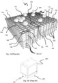
- Figs. 1A and 1C disclose a typical prior art automated storage and retrieval system 1 with a framework structure 100.
- Figs. 1B and 1D disclose prior art container handling vehicles 200,300 operating on the system 1 disclosed in Figs. 1A and 1C , respectively.
- the framework structure 100 comprises a plurality of upright members 102 and optionally a plurality of horizontal members 103 supporting the upright members 102.
- the members 102, 103 may typically be made of metal, e.g. extruded aluminum profiles.
- the framework structure 100 defines a storage grid 104 comprising storage columns 105 arranged in rows, in which storage columns 105 storage containers 106, also known as bins, are stacked one on top of another to form stacks 107.
- Each storage container 106 may typically hold a plurality of product items (not shown), and the product items within a storage container 106 may be identical, or may be of different product types depending on the application.
- the storage grid 104 guards against horizontal movement of the storage containers 106 in the stacks 107, and guides vertical movement of the storage containers 106, but does normally not otherwise support the storage containers 106 when stacked.
- the automated storage and retrieval system 1 comprises a rail system 108 arranged in a grid pattern across the top of the storage grid 104, on which rail system 108 a plurality of container handling vehicles 200,300 (as exemplified in Figs. 1B and 1D ) are operated to raise storage containers 106 from, and lower storage containers 106 into, the storage columns 105, and also to transport the storage containers 106 above the storage columns 105.
- the horizontal extent of one of the grid cells 122 constituting the grid pattern is in Figs. 1A and 1C marked by thick lines.
- Each grid cell 122 has a width which is typically within the interval of 30 to 150 cm, and a length which is typically within the interval of 50 to 200 cm.
- Each grid opening 115 has a width and a length which is typically 2 to 10 cm less than the width and the length of the grid cell 122 respectively due to the horizontal extent of the rails 110,111.
- the rail system 108 comprises a first set of parallel rails 110 arranged to guide movement of the container handling vehicles 200,300 in a first direction X across the top of the frame structure 100, and a second set of parallel rails 111 arranged perpendicular to the first set of rails 110 to guide movement of the container handling vehicles 200,300 in a second direction Y which is perpendicular to the first direction X.
- the rail system 108 defines grid columns above which the container handling vehicles 200,300 can move laterally above the storage columns 105, i.e. in a plane which is parallel to the horizontal X-Y plane.
- Each prior art container handling vehicle 200,300 comprises a vehicle body and a wheel arrangement of eight wheels 201,301 where a first set of four wheels enable the lateral movement of the container handling vehicles 200,300 in the X direction and a second set of the remaining four wheels enable the lateral movement in the Y direction.
- One or both sets of wheels in the wheel arrangement can be lifted and lowered, so that the first set of wheels and/or the second set of wheels can be engaged with the respective set of rails 110, 111 at any one time.
- Each prior art container handling vehicle 200,300 also comprises a lifting device (not shown) for vertical transportation of storage containers 106, e.g. raising a storage container 106 from, and lowering a storage container 106 into, a storage column 105.
- the lifting device comprises one or more gripping / engaging devices (not shown) which are adapted to engage a storage container 106, and which gripping / engaging devices can be lowered from the vehicle 200,300 so that the position of the gripping / engaging devices with respect to the vehicle 200,300 can be adjusted in a third direction Z which is orthogonal the first direction X and the second direction Y.
- Each container handling vehicle 200 comprises a storage compartment or space (not shown) for receiving and stowing a storage container 106 when transporting the storage container 106 across the rail system 108.
- the storage space may comprise a container receiving space arranged centrally within the vehicle body, e.g. as is described in WO2014/090684A1 .
- the container handling vehicles 300 may have a cantilever construction, as is described in NO317366 .
- the container handling vehicles 200 may have a footprint, i.e. an extent in the X and Y directions, which is generally equal to the lateral extent of a grid cell 122, i.e. the extent of a grid cell 122 in the X and Y directions, e.g. as is described in WO2015/193278A
- the term "lateral" used herein may mean "horizontal".
- the container handling vehicles 200 may have a footprint which is larger than the lateral extent of (lateral area defined by) a grid column, e.g. as is disclosed in WO2014/090684A1 .
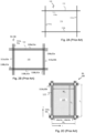
- the rail system 108 may be a single rail (also denoted single track) system, as is shown in Fig. 2A .
- the rail system 108 may be a double rail (also denoted double track) system, as is shown in Fig. 2B , thus allowing a container handling vehicle 200 having a footprint generally corresponding to the lateral area defined by a grid column 112 to travel along a row of grid columns even if another container handling vehicle 200 is positioned above a grid column neighboring that row.
- Both the single and double rail system, or a combination comprising a single and double rail arrangement in a single rail system 108 forms a grid pattern in the horizontal plane P comprising a plurality of rectangular and uniform grid locations or grid cells 122, where each grid cell 122 comprises a grid opening 115 being delimited by a pair of rails 110a, 110b of the first rails 110 and a pair of rails 111a,111b of the second set of rails 111.
- the grid cell 122 is indicated by a dashed box.
- the sections of the rail-based system being made of aluminium are the rails, and on the upper surface of the rails, there are a pair of tracks that the wheels of the vehicle run in.
- the sections could be separate rails each with a track.
- rails 110a and 110b form pairs of rails defining parallel rows of grid cells running in the X direction
- rails 111a and 111b form pairs of rails defining parallel rows of grid cells running in the Y direction.
- rails 51a and 51b form pairs of rails defining parallel rows of grid cells running in the X direction
- rails 52a and 52b form pairs of rails defining parallel rows of grid cells running in the Y direction.
- each grid cell 122 has a width W c which is typically within the interval of 30 to 150 cm, and a length L c which is typically within the interval of 50 to 200 cm.
- Each grid opening 115 has a width W o and a length L o which is typically 2 to 10 cm less than the width W c and the length L c of the grid cell 122.
- neighboring grid cells are arranged in contact with each other such that there is no space therebetween.
- a majority of the grid columns are storage columns 105, i.e. grid columns 105 where storage containers 106 are stored in stacks 107.
- a storage grid 104 normally has at least one grid column which is used not for storing storage containers 106, but which comprises a location where the container handling vehicles 200,300 can drop off and/or pick up storage containers 106 so that they can be transported to a second location (not shown) where the storage containers 106 can be accessed from outside of the storage grid 104 or transferred out of or into the storage grid 104.
- a location is normally referred to as a "port” and the grid column in which the port is located may be referred to as "port column” or "delivery column” 119,120.
- the drop-off and pick-up ports of the rail system 108 where the container handling vehicles 200,300 operate are referred to as the "upper ports of a delivery column" 119,120. While the opposite end of the delivery column is referred to as the "lower ports of a delivery column”.
- the storage grids 104 in Figs. 1A and 1C comprise two delivery columns 119 and 120.
- the first delivery column 119 may for example comprise a dedicated drop-off port where the container handling vehicles 200,300 can drop off storage containers 106 to be transported through the delivery column 119 and further to an access or a transfer station
- the second delivery column 120 may comprise a dedicated pick-up port where the container handling vehicles 200,300 can pick up storage containers 106 that have been transported through the delivery column 120 from an access or a transfer station.
- Each of the ports of the first and second delivery column may comprise a port suitable for both pick up and drop of storage containers.
- the second location may typically be a picking or a stocking station where product product items are removed from or positioned into the storage containers 106.
- the storage containers 106 are normally never removed from the automated storage and retrieval system 1, but are returned into the storage grid 104 once accessed.
- there are also lower ports provided in a delivery column such lower ports are e.g. for transferring storage containers 106 to another storage facility (e.g. to another storage grid), directly to a transport vehicle (e.g. a train or a lorry), or to a production facility.
- a transport vehicle e.g. a train or a lorry
- the automated storage and retrieval system 1 comprises a control system (not shown) which typically is computerized and which typically comprises a database for keeping track of the storage containers 106.
- a conveyor system comprising conveyors may be employed to transport the storage containers between the lower port of the delivery column and the access station.
- the conveyor system may comprise a lift device for transporting the storage containers vertically between the port and the access station.
- the conveyor system may be arranged to transfer storage containers between different grids, e.g. as is described in WO2014/075937A1 .
- WO2016/198467A1 discloses an example of a prior art access system having conveyor belts ( Figs. 5a and 5b in WO2016/198467A1 ) and a frame mounted rail ( Figs. 6a and 6b in WO2016/198467A1 ) for transporting storage containers between delivery columns and work stations where operators can access the storage containers.
- a storage container 106 stored in the storage grid 104 disclosed in Fig. 1A is to be accessed, one of the container handling vehicles 200,300 is instructed to retrieve the target storage container 106 from its position in the storage grid 104 and to transport it to or through the delivery column 119.
- This operation involves moving the container handling vehicle 200,300 to a grid location above the storage column 105 in which the target storage container 106 is positioned, retrieving the storage container 106 from the storage column 105 using the container handling vehicle's lifting device 16, and transporting the storage container 106 to the delivery column 119. If the target storage container 106 is located deep within a stack 107, i.e.
- the operation also involves temporarily moving the above-positioned storage containers prior to lifting the target storage container 106 from the storage column 105.
- This step which is sometimes referred to as "digging" within the art, may be performed with the same container handling vehicle 200,300 that is subsequently used for transporting the target storage container 106 to the delivery column, or with one or a plurality of other cooperating container handling vehicles 200,300.
- the automated storage and retrieval system 1 may have container handling vehicles 200,300 specifically dedicated to the task of temporarily removing storage containers 106 from a storage column 105. Once the target storage container 106 has been removed from the storage column 105, the temporarily removed storage containers can be repositioned into the original storage column 105. However, the removed storage containers may alternatively be relocated to other storage columns 105.
- WO 2015/140216 discloses a method of providing an operator access to a target storage position in an automated storage and retrieval system according to the preamble of claim 1 and an automated storage and retrieval system according to the preamble of claim 14.
- One objective of the present invention is thus to provide a solution which provides the firefighting crew with a possibility of visual inspection of a target storage position within an automated storage and retrieval system
- an objective of the invention is to provide a method of providing manual (i.e. operator) access to positions within the grid.
- the method thus comprises a step that the container handling vehicles follow the instructions from the master control system and remove the storage containers to make the first path.
- the first path is made once all of the storage containers in all storage columns between the position at the side edge or the top surface of the storage volume and the target storage position have been removed by the container handling vehicles.
- the master control system keeps track of any remotely operated vehicles operating on the rail system.
- Access to a specific target storage position can be desirable to provide visual inspection after a fire has occurred, in order to repair the grid, loosen or free-up unliftable storage containers within the grid etc. Access can be from above the rail system (i.e. from a top surface of the storage volume) and down into the storage column where the target storage position is, or a neighbor storage column to the storage column where the target storage position.
- the storage containers are removed or cleared by the container handling vehicle(s) in order to provide the at least first path, and may be moved to any available position within the automated storage and retrieval system or a position outside the automated storage and retrieval system.
- the available position may be an empty storage position within the storage volume or a position at a port.
- the removed storage containers may be spread to vacant storage positions in storage columns anywhere within the grid.
- An area may be set aside to receive such removed storage containers, and the area may be enclosed within a fire barrier.
- An advantage of moving said storage containers to port is that visual inspection of the storage container may be performed as well as any damage or smoke damage to item(s) stored in the storage container may be identified.
- dedicated areas of the storage system may have free capacity to receive a large amount of the removed storage containers.
- the method may further comprise, prior to the master control system allocating and instructing at least one container handling vehicle to remove storage containers along the first path, a step of:
- the first path may be a loop path enclosing the target storage position and the master control system may instruct the at least one container handling vehicle (preferably a plurality of container handling vehicles to reduce time) to remove storage containers along the loop path.
- the loop path preferably extends 360 degrees around the scene of fire.
- visual inspection may be obtained from outside of the storage volume, it may be sufficient to remove storage containers from a path in the storage volume provided that 360 degrees inspection is obtained.
- a path which extends substantially around the target position but have a section where storage containers are not removed or are only partially removed from a given stack may also be made (e.g. allowing an observer to peer around but not allowing that person to walk around easily without climbing over the remaining storage containers).
- the method may comprise collecting and evaluating information with regards to location of a scene of fire, fume, heat or smoke in the automated storage and retrieval system, where the collecting of information comprises steps of:
- the method may further comprise, in case any of the remotely operated vehicles indicates presence of fire, heat, smoke- or fume emission, the method further comprises, the steps of:
- the method may further comprise, if the master control system has decided that a reasonable prediction on location of source of the fire, fume, smoke- or heat emission can be given, the step of:
- the method may further comprise, if the master control system has decided that a reasonable prediction on location of source of the fire, fume, smoke- or heat emission can be given, the step of:
- the decision on where to remove storage containers from is a trade-off between removing containers close enough to get a good visual indication of any remaining smoke or heat emission near the target storage position and at a sufficient distance such that it is actually possible to remove the storage containers.
- the container handling vehicles may comprise a plurality of detection devices for detecting fire, fume smoke, or heat. All of the container handling vehicles operates on the rail system, and can be provided with one or more detection devices.
- the fire, fume, smoke or heat detection devices are configured to transmit data from the detection device to a master control system directly or, alternatively, via communication means present in the container handling vehicle carrying the specific detection device.
- the master control system may comprise a processing device for processing the data from the detection devices such as to create a heat map of the automated storage and retrieval system.
- the master control system keeps track of any remotely operated vehicles operating on the rail system and is configured to receive data from any of the detection device(s). This may provide valuable input in assisting in where to make a passage with regards to the location and extent of the probable scene of fire, fume, heat or smoke, in particular as the automated storage and retrieval systems increase in size (up to 110 x 150 meters and above, and with 500000 bins and more).
- the master control system may be configured to generate a temperature map or heat map based on the data.
- a temperature map or "heat map” can give valuable information in at least X and Y direction (in a horizontal plane) on where the scene of the fire, fume, heat or smoke is most likely to be located, and also information on the extent of the scene of fire, fume, heat or smoke in the X and Y directions.
- the method may further comprise the step of:
- the method thus comprises a step that the container handling vehicles follow the instructions from the master control system and remove the storage containers to make the second path.
- the method may further comprise a step of updating of the target storage position to include one or more additional column(s). For example, if a storage container outside of the initial target storage position has become damaged then it is likely that the fire has reached further than initially thought.
- the second path may be created from a different side edge of the storage volume than the first path, or the second path is created from the same side edge of the storage volume as the first path.
- the method may further comprise a step of:
- the available position may be an empty storage position or a position at a port.
- the method may provide access to an unliftable storage container within a storage column, and the step of determining the target storage position may comprise the steps of:
- an automated storage and retrieval system comprising:
- the target storage position may be determined based on required access to a target storage position in need of inspection, maintenance or repair.
- the remotely operated vehicles may be container handling vehicles comprising a lifting assembly for picking up storage containers from the storage columns to a position above the lowest level of the transport mechanism, and the lifting assembly may comprise a lifting frame connectable to a storage container, the lifting frame being configured to lift and lower the storage containers from a position in the storage column to a position above the rail system.
- the top layer of the framework 100 is a container handling vehicle rail system / rail system 108 on which a plurality of container handling vehicles 200,300 are operated.
- the framework 100 of the storage system 1 is constructed in accordance with the above mentioned prior art framework 100 described above, i.e. a plurality of upright members 102 and a plurality of horizontal members 103 which are supported by the upright members 102, and further that the horizontal members 103 includes a container handling vehicle rail system 108 of parallel rails 110,111 in the X direction and the Y direction, respectively, arranged across the top of storage columns 105.
- the horizontal area of a single grid opening 115 i.e. along the X and Y directions, may be defined by the distance between adjacent rails 110 and 111, respectively (see also Figs. 2A-2C ).
- a grid cell 122 is marked on the rail system 108 by thick lines.
- the area between adjacent rails is the grid opening 115 - the grid cell 122 is the area to the outer side edges of the opposing rails running along the opposite sides of the grid opening. Alternatively, if these are defined in terms of double-tracked rails, then the area is to the midpoint or centre of each adjacent rail.
- the container handling vehicle rail system 108 allows the container handling vehicles 200,300 to move horizontally between different grid locations, where each grid location is associated with a grid cell 122.
- the storage grid 104 is shown with a height of eight cells. It is understood, however, that the storage grid 104 can in principle be of any size. In particular it is understood that storage grid 104 can be considerably wider and/or longer than disclosed in Figs. 1A and 1C .
- the storage grid 104 may have a horizontal extent of more than 700x700 grid cells 122, or any size in between these examples, e.g. 100x100 grid cells, 200x200 grid cells, 500x500 grid cells etc.
- the grid 104 can be considerably deeper than disclosed in Figs. 1A and 1C .
- the storage grid 104 may be more than twelve grid cells deep.
- the storage grid 104 is equal or similar to the prior art storage grid 104 as described above, i.e. a storage grid 104 comprising a rail system 108; a plurality of stacks 107 of storage containers 106, a plurality of container handling vehicles 300 for lifting and moving storage containers 106 stacked in the stacks 107 and a delivery column 119,120 configured to receive a storage container 106 from a container handling vehicle 200,300.
- the rail system 108 comprises a first set of parallel trails 110 arranged in a horizontal plane (P) and extending in a first direction (X) and a second set of parallel rails 111 arranged in the horizontal plane (P) and extending in a second direction (Y) which is orthogonal to the first direction (X).
- the first and second sets of rails 110, 111 form a grid pattern in the horizontal plane (P) comprising a plurality of adjacent grid cells 122.
- Each grid cell 122 displays a grid opening defined by a pair of neighbouring rails of the first set of rails 110 and a pair of neighbouring rails of the second set of rails 111.
- the plurality of stacks 107 are arranged in storage columns 105 located beneath the rail system 108, wherein each storage column 105 is located vertically below a grid cell 122.
- Each container handling vehicle 200,300 is configured to move on the rail system 108 above the storage columns 105.
- the storage container vehicles 200,300 may be of any type known in the art, e.g. any one of the automated container handling vehicles disclosed in WO2014/090684 A1 , in NO317366 or in WO2015/193278A1 .
- the rail system 108 may be a single rail system, as is shown in Fig. 2A .
- the rail system 108 may be a double rail system, as is shown in Fig. 2B .
- the rail system 108 may be a combination of single and double rail system. Details of the single and double rail systems are disclosed in this specification under the section of background and prior art.
- FIG. 3A Perspective views of an automated storage and retrieval system are shown in Fig. 3A .
- the automated storage and retrieval system comprises a storage grid 104, onto which a plurality of container handling vehicles 200,300 operates, and a delivery system 140 comprising a delivery rail system 50 onto which a plurality of delivery vehicles 30 operates.
- the delivery vehicles 30 are provided with wheel arrangement 31 comprising first and second sets of wheels for driving the delivery vehicles in the first direction (X) and the second direction (Y).
- a master control system 800 keeps track of the container handling vehicles 200,300 operating on the storage grid 104 and the delivery vehicles 30 operating on the delivery rail system 30.
- the delivery system 140 comprises one or more of the delivery vehicles 30 as described above, i.e. delivery vehicles 30 configured to receive and support one or more storage containers 106 for transport between one or more delivery columns 119,120 of the storage grid 104 and one or more predetermined positions outside the storage grid 104.
- the predetermined positions may for example be a second location, a container accessing station, a conveyor line, another storage container, or a transport vehicle such as a truck.
- the delivery system 140 may further comprise a delivery rail system 50 situated below a delivery port of the one or more delivery columns 119,120.
- the delivery rail system 50 may be constructed in the same way or a similar way as the rail system 108 for the container handling vehicles 200,300.
- the delivery rail system 50 may comprise a first set of parallel rails 51 arranged in a horizontal plane (P1) and extending in a first direction (X), and a second set of parallel rails 52 arranged in the horizontal plane (P1) and extending in a second direction (Y) which is orthogonal to the first direction (X).
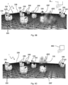
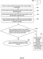
- FIGs. 3B and 3C show two examples where fume, smoke or heat emission 400 has occurred on a storage grid 104 in an automated storage and retrieval system 1.
- a plurality of container handling vehicles 200, 200' operates on a rail system 108 of a storage grid 104 in an automated storage and retrieval system 1 and communicates with a master control system 800.
- Some of the container handling vehicles 200, 200' have been equipped with fire detection device 150.
- a majority, preferably above 50%, of the container handling vehicles 200, 200' comprises a fire detection device 150, possibly together with stationary fire detection devices 150 arranged on the storage grid 104.
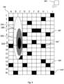
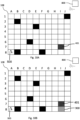
- Fig. 4 shows an example of a heat map created by the master control system based on input from a plurality of fire detection devices 150 arranged on container handling vehicles 200,300.
- fire detection devices 150 on container handling vehicles 200', 200 x such as to create a heat map 160
- order for the master control system 800 to provide the heat map 160 preferably three or more fire detection devices 150 which can provide additional input to the master control system 800 with regards to concentration of fume or smoke, or in case of heat detection, additional input from e.g. an infra-red camera or temperature sensor on the container handling vehicle 200',200 x , are utilized.
- the master control system 800 can create a heat map 160 which indicates the probable location of the source of the fume, smoke or heat emission (see Figs. 3B and 3C ).
- the disclosed heat map 160 comprises an outer portion 161 indicated by coarse-grains, an intermediate portion 161 indicated by stripes and an inner portion 162 indicated by solid black.
- the heat map 160 may indicated that it is certain that the source of the fume, smoke or heat emission 400 is within the outer portion 161, and almost certain that the source of the fume, smoke or heat emission 400 is within the striped portion 161, and very likely that the source of the fume, smoke or heat emission 400 is within the inner portion 162. If the master control system 800 has drawn up such a heat map 160, it is most promising for any fire-fighting crew to focus their initial fire-fighting in the inner portion 162 (i.e. within cell locations B7-B10 and C7-C10) on Fig. 4 .
- Fig. 5A is a flow-chart of how an operator can be provided access to a target storage position 400, 401 in an automated storage and retrieval system 1. Such an operation may include the steps of:
- Fig. 5B is a flow-chart of an example of steps to be taken in the event a container handling vehicle detects fume, smoke or heat. Such a process may include the following steps:
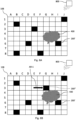
- Figs. 6A-6D are sequential step-by-step illustrations of the flow-chart of Fig. 5B , where one and one container handling vehicle 200' ...x with a fire detection device is instructed to drive to grid cells close to a container handling vehicle 200' that has detected fume, smoke or heat 400 in order for the master control system 800 to process data from the fire detection device received from the container handing vehicles 200' ...x to predict location of the source of the fume, smoke or heat 400.
- a first container handling vehicle 200' in cell H5 which first container handling vehicle 200' is provided with a fire detection device (not shown in Fig. 6A ), detects fume, smoke or heat 400.
- the first container handling vehicle 200' transmits data from the fire detection device to master control system 800.
- the master control system 800 keeps continuous track of all of the container handling vehicles 200' ...x , and thus know the position of the first container handling vehicle 201' which has detected fume, smoke or heat 400.
- the master control system 800 processes the data from the fire detection device received data from the fire detection device received from the first container handling vehicle 200'.
- the master control system 800 based on the input from the first container handling vehicle 200', has instructed a second container handling vehicle 200" initially positioned in cell E3, to move to cell G3 (as illustrated by arrow AR-1) which is closer to the first container handling vehicle 200' (and expected to be closer to the source of the fume, smoke or heat emission 400).
- cell G3 as illustrated by arrow AR-1
- the fire detection device of the second container handling vehicle 200" transmits data from the fire detection device to the master control system 800.
- the master control system 800 processes data from the fire detection device from the first and second container handling vehicles 200', 200".
- the master control system 800 based on the input from the first and second container handling vehicles 200', 200", has instructed a third container handling vehicle 200'" initially positioned in cell F8, to move to cell F6 (as illustrated by arrow AR-2) which is closer to the first and second container handling vehicles 200', 200" (and expected to be closer to the source of the fume, smoke or heat emission 400).
- cell F6 as illustrated by arrow AR-2
- the fire detection device of the third container handling vehicle 200′′′ transmits data from the fire detection device to the master control system 800.
- the master control system 800 processes data from the fire detection device from the first, second and third container handling vehicles 200', 200", 200'".
- the master control system 800 based on the processing has a reasonable prediction on the location of the source of the fume, smoke or heat 400, no further container handling vehicles 200 x are instructed to move closer to the expected source of the fume, smoke or heat emission 400.
- arranging three container handling vehicles 200', 200", 200′′′ in a triangular arrangement TA enclosing the source of the fume, smoke or heat emission 400 will be sufficient in order to establish a reasonable prediction on location of the source for the fume, smoke or heat emission 400 is.
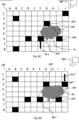
- the master control system 800 based on the input from the first, second and third container handling vehicles 200', 200", 200"', has instructed a fourth container handling vehicle 200"” initially positioned in cell 11, to move to cell J3 (as illustrated by arrow AR-3) which is closer to the first, second and or third container handling vehicles 200', 200", 200′′′ (and expected to be closer to the source of the fume, smoke or heat emission 400).
- the fire detection device of the fourth container handling vehicle 200"" transmits data from the fire detection device to the master control system 800.
- the master control system 800 processes data from the fire detection devices from the first, second, third container handling vehicles 200', 200", 200′′′, 200"".
- a total of four container handling vehicles 200', 200", 200′′′, 200"" are arranged as a four-cornered polygon PA enclosing the source of the fume, smoke or heat emission 400.
- This setup is almost certainly enough to establish a reasonable location for the source of the fume, smoke or heat emission 400.
- the master control system 800 may instruct further container handling vehicles 200 x with fire detection device to move closer to the expected location of the source of the fume, smoke or heat emission 400.
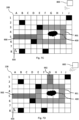
- Fig. 7A shows a scene of fire 400 after it has been extinguished by e.g. a sprinkler.
- the expected scene of fire 400 is in the storage columns represented by cells G4, G5, H4, H5 in Fig. 7A .
- a container handing vehicle(s) 200 has removed storage containers and created a loop path 901 around the scene of fire, extending 360 degrees around the scene of fire 400.
- the loop path 901 is in the storage columns represented by cells E3-E6, E6-I6, I6-I3 and I3-E3 forming a rectangular pattern (, i.e. a loop) around the scene of fire 400.
- FIG. 7C it is disclosed an example where container handing vehicle(s) 200 has removed storage containers in order to create a first path 900 extending from a position at a side edge of the storage volume 500 to the loop path around the scene of fire in Fig. 7B .
- the first path 900 is created from the side edge on the left hand side of the Figure and the storage containers in cells A5-D5 have been removed in order to create the first path 900.
- FIG. 7D it is disclosed an example where container handing vehicle(s) has removed storage containers in order to create a second path 902 extending from a position at a side edge of the storage volume 150 and to the loop path 901 around the scene of fire 400 in Figs. 7B and 7C .
- the second path 902 is created from the side edge on the top of the Figure and the storage containers in cells G1-G2 have been removed in order to create the second path 902.
- Fig. 8 shows an example where scene of fire 400, i.e. the target storage position, is close to a corner of the storage volume 500 (the down right corner in Fig. 8 ) and where container handling vehicle(s) 200 has created a L-shaped path 900 in the storage volume 500.
- the L-shaped path 900 extends between a first side edge of the storage volume 150 to a second side edge of the storage volume 500.
- the path 900 in Fig. 8 extends through the storage columns represented by cell G8-G6 and G6-J6.
- 360 degrees visual inspection is achieved from the outside of the storage volume 500, i.e. the two side edges on the right hand side in the Figure and the lower side, respectively.
- Fig. 9A shows an example of an unliftable storage container in a storage volume 150.
- the unliftable storage container is in a target storage position 401 represented by cell numbered F4.
- Fig. 9B shows an example where container handling vehicle(s) has removed storage containers in order to create a first path 900 from a position at a side edge of the storage volume 150 and to the unliftable storage container in target storage position 401.
- the first path 900 in Fig. 9B extends from the lower side edge at the storage column represented by cell G8 to storage column represented by cell G4, via positions G7, G6 and G5.
- Fig. 10A shows an unliftable storage container in a storage volume 150 at a different position than the unliftable storage container in Fig. 9A .
- the unliftable storage container is in a target storage position 401 represented by cell I7.
- FIG. 10B it is shown an example where container handling vehicle(s) 200 has removed storage containers in order to create a first path 900 that extends from a position at a lower side edge of the storage volume 150 and to the unliftable storage container in Fig. 10A .
- Fig. 11 is a perspective view of an automated storage and retrieval system 1 illustrating that the system may have side panel(s) 25 on the side edges.
- the side panel(s) 25 can be removed in order to be able to access the storage volume 150 below the rail system 108 at ground level.
Landscapes
- Engineering & Computer Science (AREA)
- Business, Economics & Management (AREA)
- Health & Medical Sciences (AREA)
- Public Health (AREA)
- Emergency Management (AREA)
- Mechanical Engineering (AREA)
- Operations Research (AREA)
- Economics (AREA)
- Human Resources & Organizations (AREA)
- Physics & Mathematics (AREA)
- Development Economics (AREA)
- Marketing (AREA)
- Quality & Reliability (AREA)
- Strategic Management (AREA)
- Tourism & Hospitality (AREA)
- Entrepreneurship & Innovation (AREA)
- General Business, Economics & Management (AREA)
- General Physics & Mathematics (AREA)
- Theoretical Computer Science (AREA)
- Warehouses Or Storage Devices (AREA)
- Platform Screen Doors And Railroad Systems (AREA)
- Automatic Disk Changers (AREA)
Claims (14)
- Verfahren zum Bereitstellen eines Bedienerzugriffs auf eine Ziellagerposition (400, 401) in einem automatischen Regalbedienungssystem (1), wobei das automatische Regalbedienungssystem (1) Folgendes umfasst:ein Schienensystem (108) zum Führen einer Vielzahl von Containertransportfahrzeugen (200, 300), wobei das Schienensystem (108) einen ersten Satz von parallelen Schienen (110), der in einer horizontalen Ebene (P) angeordnet ist und sich in einer ersten Richtung (X) erstreckt, und einen zweiten Satz von parallelen Schienen (111), der in der horizontalen Ebene (P) angeordnet ist und sich in einer zweiten Richtung (Y) erstreckt, die senkrecht zu der ersten Richtung (X) ist, umfasst, wobei der erste und der zweite Satz von Schienen (110, 111) ein Gittermuster in der horizontalen Ebene (P) bilden, das eine Vielzahl von aneinander angrenzenden Gitterzellen (122) umfasst, wobei jede Gitterzelle (122) eine Gitteröffnung (115) umfasst, die durch ein Paar von benachbarten Schienen (110a, 110b) des ersten Satzes von Schienen (110) und ein Paar von benachbarten Schienen (111a, 111b) des zweiten Satzes von Schienen (111) definiert ist; wobei das automatische Regalbedienungssystem (1) ferner ein Lagervolumen (500) unterhalb des Schienensystems (108) umfasst, wobei das Lagervolumen (500) Lagersäulen zum Lagern von Lagercontainern (106) umfasst und die Containertransportfahrzeuge (200, 300) dazu betreibbar sind, einen Lagercontainer (106) aus einem Stapel (107) von Lagercontainern innerhalb des Lagervolumens (500) zu holen,wobei das Verfahren dadurch gekennzeichnet ist, dass es die folgenden Schritte umfasst:- Betreiben eines übergeordneten Steuersystems (800), um mindestens ein Containertransportfahrzeug (200, 300) zuzuweisen und dazu anzuweisen, Lagercontainer entlang eines ersten Wegs (900) zwischen einer Position an einem Seitenrand oder einer Oberseite des Lagervolumens (500) und der Ziellagerposition (400, 401) derart zu entfernen, dass ein Bediener auf die Ziellagerposition über den ersten Weg (900) zugreifen kann, wenn das mindestens eine Containertransportfahrzeug (200, 300) die Lagercontainer (106) entlang des ersten Wegs entfernt hat.
- Verfahren nach Anspruch 1, wobei das Verfahren einen folgenden Schritt umfasst:- Bestimmen einer Ziellagerposition.
- Verfahren nach Anspruch 1, wobei der erste Weg ein Rundweg (901) ist, der die Ziellagerposition umschließt, und wobei das übergeordnete Steuersystem (800) das mindestens eine Containertransportfahrzeug dazu anweist, Lagercontainer entlang des Rundwegs (901) zu entfernen.
- Verfahren nach einem der vorhergehenden Ansprüche, wobei das Verfahren Sammeln und Auswerten von Informationen in Bezug auf den Ort einer Szene mit Feuer, Qualm, Hitze oder Rauch in dem automatischen Regalbedienungssystem (1) umfasst, wobei das Sammeln von Informationen folgende Schritte umfasst:- Betreiben einer Vielzahl von ferngesteuerten Fahrzeugen (200, 300) auf dem Schienensystem (108), wobei jedes der ferngesteuerten Fahrzeuge (200, 300) mit einer Erkennungsvorrichtung (150) zum Erkennen von Feuer, Hitze, Qualm oder Rauch versehen ist und wobei die Erkennungsvorrichtungen (150) dazu ausgelegt sind, Daten von den Erkennungsvorrichtungen an das übergeordnete Steuersystem (800) über Kommunikationsmittel in dem Containertransportfahrzeug zu übertragen, das die Erkennungsvorrichtung (150) trägt, welche die Informationen gesammelt hat; und- Nutzen des übergeordneten Steuersystems, um Daten von einer der Erkennungsvorrichtungen (150) zu verarbeiten, und Verwenden des übergeordneten Steuersystems (800), um Informationen zu dem Ort der Szene mit Feuer, Qualm, Hitze oder Rauch bereitzustellen; und- Nutzen des übergeordneten Steuersystems, um zu bestimmen, wo Lagercontainer entfernt werden müssen, um den ersten Weg (900) zu erzeugen.
- Verfahren nach Anspruch 4, wobei in dem Fall, dass eines der ferngesteuerten Fahrzeuge (200') ein Vorhandensein von Feuer-, Hitze-, Rauch- oder Qualmemissionen angibt, das Verfahren ferner die folgenden Schritte umfasst:- Zuweisen eines anderen ferngesteuerten Fahrzeugs (200‴) mit einer Erkennungsvorrichtung (150) zum Erkennen von Feuer, Hitze, Qualm oder Rauch, um sich in eine Zelle in der Nähe der Position der ferngesteuerten Fahrzeuge (200', 200") zu bewegen, die ein Vorhandensein von Feuer-, Hitze-, Rauch- oder Qualemissionen anzeigen; und- Nutzen des übergeordneten Steuersystems (800), um die Daten von den Erkennungsvorrichtungen von den ferngesteuerten Fahrzeugen (200', 200", 200"') zu verarbeiten, wobei das übergeordnete Steuersystem (800) auf Grundlage der Verarbeitung der Informationen von den Erkennungsvorrichtungen entscheidet, ob eine sinnvolle Vorhersage zu dem Ort einer Quelle (400) der Feuer-, Qualm-, Rauch- oder Hitzeemissionen erteilt werden kann.
- Verfahren nach Anspruch 5, wobei, wenn das übergeordnete Steuersystem (800) entschieden hat, dass eine sinnvolle Vorhersage zu dem Ort der Quelle (400) der Feuer-, Qualm-, Rauch- oder Hitzeemissionen erteilt werden kann, das Verfahren den folgenden Schritt umfasst:- Nutzen des übergeordneten Steuersystems (800), um die Position der Quelle der Feuer-, Qualm-, Rauch- oder Hitzeemissionen (400) in Form einer dreieckigen Anordnung (TA) durch Vergleichen von Informationen von mindestens drei Erkennungsvorrichtungen zu bestimmen.
- Verfahren nach Anspruch 6, wobei, wenn das übergeordnete Steuersystem (800) entschieden hat, dass eine sinnvolle Vorhersage zu dem Ort der Quelle (400) der Feuer-, Qualm-, Rauch- oder Hitzeemissionen erteilt werden kann, das Verfahren den folgenden Schritt umfasst:- Nutzen des übergeordneten Steuersystems (800), um die Position der Quelle der Feuer-, Qualm-, Rauch- oder Hitzeemissionen (400) in Form einer viereckigen Polygonanordnung (PA) durch Vergleichen von Informationen von mindestens vier Erkennungsvorrichtungen zu bestimmen.
- Verfahren nach einem der vorhergehenden Ansprüche, umfassend den folgenden Schritt:- Betreiben eines übergeordneten Steuersystems (800), um mindestens ein Containertransportfahrzeug zuzuweisen und dazu anzuweisen, Lagercontainer entlang eines zweiten Wegs zwischen einer Position an einem Seitenrand des Lagervolumens (500) und der Ziellagerposition derart zu entfernen, dass ein Bediener auf die Ziellagerposition über einen beliebigen von dem ersten und/oder dem zweiten Weg zugreifen kann.
- Verfahren nach Anspruch 8, wobei der zweite Weg von einem anderen Seitenrand des Lagervolumens (500) aus als der erste Weg erzeugt wird oder der zweite Weg von dem gleichen Seitenrand des Lagervolumens (500) aus wie der erste Weg erzeugt wird.
- Verfahren nach einem der vorhergehenden Ansprüche, ferner umfassend einen folgenden Schritt:- Nutzen des übergeordneten Steuersystems (800), um zu bestimmen, wohin die Lagercontainer von dem/den Weg(en) zu bewegen sind und auf Grundlage davon, wo verfügbare Positionen gefunden werden, einen folgenden Schritt:- Anweisen des/der Containertransportfahrzeugs/-e (200', 200", 200‴), die Lagercontainer an eine der verfügbaren Position(en) zu bewegen.
- Verfahren nach Anspruch 10, wobei die verfügbare Position eine leere Lagerposition oder eine Position an einer Arbeitsstation ist.
- Verfahren nach einem der vorhergehenden Ansprüche, wobei das Verfahren Zugriff auf einen nicht anhebbaren Lagercontainer (401) innerhalb einer Lagersäule bereitstellt und wobei der Schritt des Bestimmens der Lagerzielposition die folgenden Schritte umfasst:- Empfangen von Informationen von einem Containertransportfahrzeug, die angeben, dass ein Lagercontainer an der Ziellagerposition nicht anhebbar ist;- Nutzen des übergeordneten Steuersystems (800), um Lagercontainer entlang des ersten Wegs (900) zwischen der Position an dem Seitenrand des Lagervolumens und der Ziellagerposition zu entfernen, an der sich der nicht anhebbare Lagercontainer (401) befindet, sodass ein Bediener auf den nicht anhebbaren Lagercontainer (401) zugreifen kann.
- Verfahren nach einem der vorhergehenden Ansprüche, wobei die Ziellagerposition auf Grundlage eines erforderlichen Zugriffs auf eine Ziellagerposition bestimmt wird, die einer Inspektion, Wartung oder Reparatur bedarf.
- Automatisches Regalbedienungssystem (1), wobei das automatische Regalbedienungssystem (1) Folgendes umfasst:- ein Schienensystem (108) zum Führen einer Vielzahl von Containertransportfahrzeugen (200, 300), wobei das Schienensystem (108) einen ersten Satz von parallelen Schienen (110), der in einer horizontalen Ebene (P) angeordnet ist und sich in einer ersten Richtung (X) erstreckt, und einen zweiten Satz von parallelen Schienen (111), der in der horizontalen Ebene (P) angeordnet ist und sich in einer zweiten Richtung (Y) erstreckt, die senkrecht zu der ersten Richtung (X) ist, umfasst, wobei der erste und der zweite Satz von Schienen (110, 111) ein Gittermuster in der horizontalen Ebene (P) bilden, das eine Vielzahl von aneinander angrenzenden Gitterzellen (122) umfasst, wobei jede Gitterzelle (122) eine Gitteröffnung (115) umfasst, die durch ein Paar von benachbarten Schienen (110a, 110b) des ersten Satzes von Schienen (110) und ein Paar von benachbarten Schienen (111a, 111b) des zweiten Satzes von Schienen (111) definiert ist;- ein Lagervolumen (500) unterhalb des Schienensystems (108), wobei das Lagervolumen (500) Lagersäulen zum Lagern von Lagercontainern (106) umfasst und die Containertransportfahrzeuge (200, 300) dazu betreibbar sind, einen Lagercontainer (106) aus einem Stapel (107) von Lagercontainern innerhalb des Lagervolumens (500) zu holen,- mindestens ein Containertransportfahrzeug (200, 300), das auf dem Schienensystem (108) betreibbar ist, wobei das Containertransportfahrzeug (200, 300) eine Hubanordnung zum Aufnehmen von Lagercontainern aus den Lagersäulen in eine Position über der niedrigsten Ebene des Transportmechanismus umfasst und die Hubanordnung einen Hubrahmen umfasst, der mit einem Lagercontainer verbindbar ist, wobei der Hubrahmen dazu ausgelegt ist, die Lagercontainer (106) aus einer Position in der Lagersäule in eine Position über dem Schienensystem (108) anzuheben und abzusenken; gekennzeichnet durch- ein übergeordnetes Steuersystem (800), das dazu ausgelegt ist, mindestens eines von dem Containertransportfahrzeug (200, 300) zuzuweisen und dazu anzuweisen, Lagercontainer entlang eines ersten Wegs (900) zwischen einer Position an einem Seitenrand oder einer Oberseite des Lagervolumens (500) und der Ziellagerposition (400, 401) innerhalb des Lagervolumens (500) derart zu entfernen, dass ein Bediener auf die Ziellagerposition (400, 401) über den ersten Weg (900) zugreifen kann, wenn das mindestens eine Containertransportfahrzeug die Lagercontainer entlang des ersten Wegs (900) entfernt hat.
Priority Applications (1)
| Application Number | Priority Date | Filing Date | Title |
|---|---|---|---|
| EP23178656.7A EP4249083A3 (de) | 2019-09-02 | 2020-08-21 | Verfahren und system zur bereitstellung eines bedienerzugriffs auf eine zielspeicherposition in einem automatischen regalbedienungssystem |
Applications Claiming Priority (2)
| Application Number | Priority Date | Filing Date | Title |
|---|---|---|---|
| NO20191053A NO347754B1 (en) | 2019-09-02 | 2019-09-02 | Method, and associated system, of providing an operator access to a target storage position in an automated storage and retrieval system |
| PCT/EP2020/073453 WO2021043597A1 (en) | 2019-09-02 | 2020-08-21 | Method, and associated system, of providing an operator access to a target storage position in an automated storage and retrieval system |
Related Child Applications (2)
| Application Number | Title | Priority Date | Filing Date |
|---|---|---|---|
| EP23178656.7A Division-Into EP4249083A3 (de) | 2019-09-02 | 2020-08-21 | Verfahren und system zur bereitstellung eines bedienerzugriffs auf eine zielspeicherposition in einem automatischen regalbedienungssystem |
| EP23178656.7A Division EP4249083A3 (de) | 2019-09-02 | 2020-08-21 | Verfahren und system zur bereitstellung eines bedienerzugriffs auf eine zielspeicherposition in einem automatischen regalbedienungssystem |
Publications (2)
| Publication Number | Publication Date |
|---|---|
| EP4025524A1 EP4025524A1 (de) | 2022-07-13 |
| EP4025524B1 true EP4025524B1 (de) | 2023-07-26 |
Family
ID=72193466
Family Applications (2)
| Application Number | Title | Priority Date | Filing Date |
|---|---|---|---|
| EP20760836.5A Active EP4025524B1 (de) | 2019-09-02 | 2020-08-21 | Verfahren und system zur bereitstellung eines bedienerzugriffs auf eine zielspeicherposition in einem automatischen regalbedienungssystem |
| EP23178656.7A Pending EP4249083A3 (de) | 2019-09-02 | 2020-08-21 | Verfahren und system zur bereitstellung eines bedienerzugriffs auf eine zielspeicherposition in einem automatischen regalbedienungssystem |
Family Applications After (1)
| Application Number | Title | Priority Date | Filing Date |
|---|---|---|---|
| EP23178656.7A Pending EP4249083A3 (de) | 2019-09-02 | 2020-08-21 | Verfahren und system zur bereitstellung eines bedienerzugriffs auf eine zielspeicherposition in einem automatischen regalbedienungssystem |
Country Status (11)
| Country | Link |
|---|---|
| US (1) | US12434911B2 (de) |
| EP (2) | EP4025524B1 (de) |
| JP (2) | JP7624974B2 (de) |
| KR (1) | KR102936978B1 (de) |
| CN (2) | CN116674924A (de) |
| CA (1) | CA3148880A1 (de) |
| DK (1) | DK4025524T3 (de) |
| ES (1) | ES2954437T3 (de) |
| NO (1) | NO347754B1 (de) |
| PL (1) | PL4025524T3 (de) |
| WO (1) | WO2021043597A1 (de) |
Families Citing this family (6)
| Publication number | Priority date | Publication date | Assignee | Title |
|---|---|---|---|---|
| CA3098972A1 (en) | 2018-06-12 | 2019-12-19 | Autostore Technology AS | Container accessing station with lifting device |
| GB201904827D0 (en) * | 2018-11-14 | 2019-05-22 | Ocado Innovation Ltd | Container-manoeuvring apparatus |
| NO345928B1 (en) * | 2019-08-27 | 2021-10-25 | Autostore Tech As | Bin ventilation system |
| DE102023101670A1 (de) * | 2023-01-24 | 2024-07-25 | Amova Gmbh | Feuerlöschkonzept in Hochregallager II |
| CN116374459B (zh) * | 2023-03-03 | 2025-02-07 | 北京极智嘉科技股份有限公司 | 仓储系统和仓储方法 |
| WO2025259922A1 (en) * | 2024-06-12 | 2025-12-18 | Mytra, Inc. | System and method for multi-rack storage |
Family Cites Families (35)
| Publication number | Priority date | Publication date | Assignee | Title |
|---|---|---|---|---|
| JPH0991567A (ja) * | 1995-09-25 | 1997-04-04 | Nippon Yusoki Co Ltd | 環境防災管理システム |
| JPH1135117A (ja) * | 1997-07-11 | 1999-02-09 | Yokin Kofun Yugenkoshi | 資材納入・ピックアップシステム |
| NO317366B1 (no) | 1999-07-01 | 2004-10-18 | Autostore As | Lagringsanlegg med fjernstyrte vogner med to hjulsett og heisinnretning for drift på skinner anlagt i kryss over kolonner av lagringsenheter som er adskilt med vertikale profilstolper |
| US20070065259A1 (en) | 2005-08-30 | 2007-03-22 | Talley Paul A | Automated self storage system |
| JP4729031B2 (ja) | 2007-11-19 | 2011-07-20 | 日本通運株式会社 | 保管荷物のロケーション管理システム |
| JP4715868B2 (ja) * | 2008-06-04 | 2011-07-06 | 村田機械株式会社 | 搬送走行車システム |
| AU2009100534B4 (en) * | 2009-06-02 | 2010-05-20 | Magnum Rental Pty Ltd | Vehicle mounted unmanned water cannon |
| JP2011155156A (ja) * | 2010-01-27 | 2011-08-11 | Muratec Automation Co Ltd | 物品搬送装置 |
| EP2563698B1 (de) * | 2010-04-30 | 2021-12-01 | David Alba | System zum transport, zur lagerung und zur verteilung intermodaler container |
| US8694152B2 (en) * | 2010-12-15 | 2014-04-08 | Symbotic, LLC | Maintenance access zones for storage and retrieval systems |
| TWI622540B (zh) * | 2011-09-09 | 2018-05-01 | 辛波提克有限責任公司 | 自動化儲存及取放系統 |
| NO334806B1 (no) | 2012-11-13 | 2014-06-02 | Jakob Hatteland Logistics As | Lagringssystem |
| NO335839B1 (no) * | 2012-12-10 | 2015-03-02 | Jakob Hatteland Logistics As | Robot for transport av lagringsbeholdere |
| GB201404870D0 (en) * | 2014-03-18 | 2014-04-30 | Ocado Ltd | Robotic service device and handling method |
| GB201314313D0 (en) * | 2013-08-09 | 2013-09-25 | Ocado Ltd | Apparatus for retrieving units from a storage system |
| US9280157B2 (en) * | 2013-09-04 | 2016-03-08 | Amazon Technologies, Inc. | System and method for transporting personnel within an active workspace |
| JP5835368B2 (ja) | 2014-01-27 | 2015-12-24 | 株式会社ダイフク | 物品搬送設備 |
| DE202014003113U1 (de) * | 2014-04-10 | 2014-04-24 | Raumaster Paper Oy | Meldeanlage und Vertikalrollenlager |
| NO337544B1 (no) | 2014-06-19 | 2016-05-02 | Jakob Hatteland Logistics As | Fjernstyrt kjøretøysammenstilling for å plukke opp lagringsbeholdere fra et lagringssystem |
| US10549914B2 (en) * | 2015-04-15 | 2020-02-04 | Ocado Innovation Limited | Storage systems and methods |
| GB201602332D0 (en) * | 2015-04-15 | 2016-03-23 | Ocado Innovation Ltd | Robotic container handling device and method |
| GB201509921D0 (en) | 2015-06-08 | 2015-07-22 | Ocado Innovation Ltd | Object storage, handling and retrieving system and method |
| NO340577B1 (en) * | 2015-09-04 | 2017-05-15 | Jakob Hatteland Logistics As | Method for fetching a target bin stored in a storage system and a storage system which includes a control device operating in accordance with the method |
| GB201521488D0 (en) * | 2015-12-06 | 2016-01-20 | Ocado Innovation Ltd | Sequencing systems and methods |
| GB201603518D0 (en) | 2016-02-29 | 2016-04-13 | Ocado Innovation Ltd | Robotic fire extinguishing device and handling method |
| GB201604100D0 (en) * | 2016-03-10 | 2016-04-20 | Ocado Innovation Ltd | Apparatus for retrieving units from a storage system |
| GB201716201D0 (en) * | 2017-10-04 | 2017-11-15 | Ocado Innovation Ltd | Object handling coordination system and method of relocating a transporting vessel |
| NO344407B1 (en) | 2017-10-24 | 2019-12-02 | Autostore Tech As | Automated storage and retrieval system and method of providing access to equipment |
| NO346519B1 (en) * | 2017-11-02 | 2022-09-19 | Autostore Tech As | An automated storage and retrieval system, use of a multi trolley vehicle on the system and a method of operating the system |
| HUE070376T2 (hu) * | 2018-06-08 | 2025-06-28 | Attabotics Inc | Továbbfejlesztett tároló és kitároló rendszerek |
| CN108646762B (zh) | 2018-07-17 | 2020-01-14 | 北京极智嘉科技有限公司 | 机器人的消防控制方法、装置、服务器和存储介质 |
| CN109230321B (zh) * | 2018-10-12 | 2020-07-21 | 上海大族富创得科技有限公司 | 物料传输系统、传输方法及存储装置 |
| US20230028034A1 (en) * | 2019-08-26 | 2023-01-26 | Attabotics Inc. | Multi-zone automated storage and retrieval system |
| US20230356014A1 (en) * | 2020-10-29 | 2023-11-09 | Tyco Fire Products Lp | Controlled system and methods of automated storage and retrieval system fire protection |
| CN116745218A (zh) * | 2020-11-23 | 2023-09-12 | 瑞仕格物流公司 | 具有多方向车的自动储存和取回系统 |
-
2019
- 2019-09-02 NO NO20191053A patent/NO347754B1/en unknown
-
2020
- 2020-08-21 DK DK20760836.5T patent/DK4025524T3/da active
- 2020-08-21 PL PL20760836.5T patent/PL4025524T3/pl unknown
- 2020-08-21 EP EP20760836.5A patent/EP4025524B1/de active Active
- 2020-08-21 JP JP2022513497A patent/JP7624974B2/ja active Active
- 2020-08-21 EP EP23178656.7A patent/EP4249083A3/de active Pending
- 2020-08-21 CN CN202310854522.7A patent/CN116674924A/zh active Pending
- 2020-08-21 ES ES20760836T patent/ES2954437T3/es active Active
- 2020-08-21 CN CN202080061692.4A patent/CN114341028B/zh active Active
- 2020-08-21 KR KR1020227006279A patent/KR102936978B1/ko active Active
- 2020-08-21 US US17/634,376 patent/US12434911B2/en active Active
- 2020-08-21 CA CA3148880A patent/CA3148880A1/en active Pending
- 2020-08-21 WO PCT/EP2020/073453 patent/WO2021043597A1/en not_active Ceased
-
2025
- 2025-01-21 JP JP2025008328A patent/JP2025061535A/ja active Pending
Also Published As
| Publication number | Publication date |
|---|---|
| EP4025524A1 (de) | 2022-07-13 |
| PL4025524T3 (pl) | 2023-09-25 |
| NO347754B1 (en) | 2024-03-18 |
| US12434911B2 (en) | 2025-10-07 |
| JP2025061535A (ja) | 2025-04-10 |
| CN114341028A (zh) | 2022-04-12 |
| ES2954437T3 (es) | 2023-11-22 |
| EP4249083A3 (de) | 2023-11-22 |
| US20220281684A1 (en) | 2022-09-08 |
| EP4249083A2 (de) | 2023-09-27 |
| WO2021043597A1 (en) | 2021-03-11 |
| CN116674924A (zh) | 2023-09-01 |
| CN114341028B (zh) | 2023-06-30 |
| CA3148880A1 (en) | 2021-03-11 |
| JP7624974B2 (ja) | 2025-01-31 |
| DK4025524T3 (da) | 2023-09-04 |
| KR102936978B1 (ko) | 2026-03-11 |
| KR20220050903A (ko) | 2022-04-25 |
| NO20191053A1 (en) | 2021-03-03 |
| JP2022546481A (ja) | 2022-11-04 |
Similar Documents
| Publication | Publication Date | Title |
|---|---|---|
| EP4025524B1 (de) | Verfahren und system zur bereitstellung eines bedienerzugriffs auf eine zielspeicherposition in einem automatischen regalbedienungssystem | |
| US12151894B2 (en) | System and applicable methods of collecting items from storage containers using robotic operator | |
| WO2018233886A1 (en) | Storage system and container handling station | |
| US12296864B2 (en) | Delivery system with an access point and a method of accessing an access point of the delivery system | |
| US20250050145A1 (en) | Automated grid storage and retrieval system with passive fire prevention arrangement | |
| US20250371955A1 (en) | An automated storage and retrieval system with fire detection device and methods of locating and/or verifying fire or smoke in an automated storage and retrieval system | |
| EP4196417A1 (de) | System und verfahren zur erkennung von anomalien in den spuren eines dreidimensionalen speichersystems | |
| NO346210B1 (en) | Method for handling malfunctioning vehicles on a rail system and a storage and retrieval system using such a method | |
| US12311207B2 (en) | Automated grid storage and retrieval system with foam-based fire prevention system | |
| HK40063202A (en) | Method, and associated system, of providing an operator access to a target storage position in an automated storage and retrieval system | |
| HK40090188A (zh) | 用於自动化仓储系统的主控制系统 | |
| HK40063202B (en) | Method, and associated system, of providing an operator access to a target storage position in an automated storage and retrieval system |
Legal Events
| Date | Code | Title | Description |
|---|---|---|---|
| STAA | Information on the status of an ep patent application or granted ep patent |
Free format text: STATUS: UNKNOWN |
|
| STAA | Information on the status of an ep patent application or granted ep patent |
Free format text: STATUS: THE INTERNATIONAL PUBLICATION HAS BEEN MADE |
|
| PUAI | Public reference made under article 153(3) epc to a published international application that has entered the european phase |
Free format text: ORIGINAL CODE: 0009012 |
|
| STAA | Information on the status of an ep patent application or granted ep patent |
Free format text: STATUS: REQUEST FOR EXAMINATION WAS MADE |
|
| 17P | Request for examination filed |
Effective date: 20220317 |
|
| AK | Designated contracting states |
Kind code of ref document: A1 Designated state(s): AL AT BE BG CH CY CZ DE DK EE ES FI FR GB GR HR HU IE IS IT LI LT LU LV MC MK MT NL NO PL PT RO RS SE SI SK SM TR |
|
| DAV | Request for validation of the european patent (deleted) | ||
| DAX | Request for extension of the european patent (deleted) | ||
| GRAP | Despatch of communication of intention to grant a patent |
Free format text: ORIGINAL CODE: EPIDOSNIGR1 |
|
| STAA | Information on the status of an ep patent application or granted ep patent |
Free format text: STATUS: GRANT OF PATENT IS INTENDED |
|
| RIC1 | Information provided on ipc code assigned before grant |
Ipc: A62C 3/00 20060101ALI20230310BHEP Ipc: A62C 27/00 20060101ALI20230310BHEP Ipc: B65G 1/137 20060101ALI20230310BHEP Ipc: B65G 1/04 20060101AFI20230310BHEP |
|
| INTG | Intention to grant announced |
Effective date: 20230411 |
|
| GRAS | Grant fee paid |
Free format text: ORIGINAL CODE: EPIDOSNIGR3 |
|
| GRAA | (expected) grant |
Free format text: ORIGINAL CODE: 0009210 |
|
| STAA | Information on the status of an ep patent application or granted ep patent |
Free format text: STATUS: THE PATENT HAS BEEN GRANTED |
|
| P01 | Opt-out of the competence of the unified patent court (upc) registered |
Effective date: 20230524 |
|
| AK | Designated contracting states |
Kind code of ref document: B1 Designated state(s): AL AT BE BG CH CY CZ DE DK EE ES FI FR GB GR HR HU IE IS IT LI LT LU LV MC MK MT NL NO PL PT RO RS SE SI SK SM TR |
|
| REG | Reference to a national code |
Ref country code: CH Ref legal event code: EP |
|
| REG | Reference to a national code |
Ref country code: IE Ref legal event code: FG4D |
|
| REG | Reference to a national code |
Ref country code: DE Ref legal event code: R096 Ref document number: 602020014550 Country of ref document: DE |
|
| REG | Reference to a national code |
Ref country code: DK Ref legal event code: T3 Effective date: 20230829 |
|
| REG | Reference to a national code |
Ref country code: SE Ref legal event code: TRGR |
|
| REG | Reference to a national code |
Ref country code: NL Ref legal event code: FP |
|
| REG | Reference to a national code |
Ref country code: LT Ref legal event code: MG9D |
|
| REG | Reference to a national code |
Ref country code: GB Ref legal event code: 732E Free format text: REGISTERED BETWEEN 20231019 AND 20231025 |
|
| REG | Reference to a national code |
Ref country code: ES Ref legal event code: FG2A Ref document number: 2954437 Country of ref document: ES Kind code of ref document: T3 Effective date: 20231122 |
|
| REG | Reference to a national code |
Ref country code: AT Ref legal event code: MK05 Ref document number: 1591727 Country of ref document: AT Kind code of ref document: T Effective date: 20230726 |
|
| PG25 | Lapsed in a contracting state [announced via postgrant information from national office to epo] |
Ref country code: GR Free format text: LAPSE BECAUSE OF FAILURE TO SUBMIT A TRANSLATION OF THE DESCRIPTION OR TO PAY THE FEE WITHIN THE PRESCRIBED TIME-LIMIT Effective date: 20231027 |
|
| PG25 | Lapsed in a contracting state [announced via postgrant information from national office to epo] |
Ref country code: IS Free format text: LAPSE BECAUSE OF FAILURE TO SUBMIT A TRANSLATION OF THE DESCRIPTION OR TO PAY THE FEE WITHIN THE PRESCRIBED TIME-LIMIT Effective date: 20231126 |
|
| PG25 | Lapsed in a contracting state [announced via postgrant information from national office to epo] |
Ref country code: RS Free format text: LAPSE BECAUSE OF FAILURE TO SUBMIT A TRANSLATION OF THE DESCRIPTION OR TO PAY THE FEE WITHIN THE PRESCRIBED TIME-LIMIT Effective date: 20230726 Ref country code: PT Free format text: LAPSE BECAUSE OF FAILURE TO SUBMIT A TRANSLATION OF THE DESCRIPTION OR TO PAY THE FEE WITHIN THE PRESCRIBED TIME-LIMIT Effective date: 20231127 Ref country code: NO Free format text: LAPSE BECAUSE OF FAILURE TO SUBMIT A TRANSLATION OF THE DESCRIPTION OR TO PAY THE FEE WITHIN THE PRESCRIBED TIME-LIMIT Effective date: 20231026 Ref country code: LV Free format text: LAPSE BECAUSE OF FAILURE TO SUBMIT A TRANSLATION OF THE DESCRIPTION OR TO PAY THE FEE WITHIN THE PRESCRIBED TIME-LIMIT Effective date: 20230726 Ref country code: LT Free format text: LAPSE BECAUSE OF FAILURE TO SUBMIT A TRANSLATION OF THE DESCRIPTION OR TO PAY THE FEE WITHIN THE PRESCRIBED TIME-LIMIT Effective date: 20230726 Ref country code: IS Free format text: LAPSE BECAUSE OF FAILURE TO SUBMIT A TRANSLATION OF THE DESCRIPTION OR TO PAY THE FEE WITHIN THE PRESCRIBED TIME-LIMIT Effective date: 20231126 Ref country code: HR Free format text: LAPSE BECAUSE OF FAILURE TO SUBMIT A TRANSLATION OF THE DESCRIPTION OR TO PAY THE FEE WITHIN THE PRESCRIBED TIME-LIMIT Effective date: 20230726 Ref country code: GR Free format text: LAPSE BECAUSE OF FAILURE TO SUBMIT A TRANSLATION OF THE DESCRIPTION OR TO PAY THE FEE WITHIN THE PRESCRIBED TIME-LIMIT Effective date: 20231027 Ref country code: FI Free format text: LAPSE BECAUSE OF FAILURE TO SUBMIT A TRANSLATION OF THE DESCRIPTION OR TO PAY THE FEE WITHIN THE PRESCRIBED TIME-LIMIT Effective date: 20230726 Ref country code: AT Free format text: LAPSE BECAUSE OF FAILURE TO SUBMIT A TRANSLATION OF THE DESCRIPTION OR TO PAY THE FEE WITHIN THE PRESCRIBED TIME-LIMIT Effective date: 20230726 |
|
| PG25 | Lapsed in a contracting state [announced via postgrant information from national office to epo] |
Ref country code: LU Free format text: LAPSE BECAUSE OF NON-PAYMENT OF DUE FEES Effective date: 20230821 |
|
| REG | Reference to a national code |
Ref country code: DE Ref legal event code: R097 Ref document number: 602020014550 Country of ref document: DE |
|
| PG25 | Lapsed in a contracting state [announced via postgrant information from national office to epo] |
Ref country code: EE Free format text: LAPSE BECAUSE OF FAILURE TO SUBMIT A TRANSLATION OF THE DESCRIPTION OR TO PAY THE FEE WITHIN THE PRESCRIBED TIME-LIMIT Effective date: 20230726 Ref country code: SM Free format text: LAPSE BECAUSE OF FAILURE TO SUBMIT A TRANSLATION OF THE DESCRIPTION OR TO PAY THE FEE WITHIN THE PRESCRIBED TIME-LIMIT Effective date: 20230726 Ref country code: RO Free format text: LAPSE BECAUSE OF FAILURE TO SUBMIT A TRANSLATION OF THE DESCRIPTION OR TO PAY THE FEE WITHIN THE PRESCRIBED TIME-LIMIT Effective date: 20230726 Ref country code: LU Free format text: LAPSE BECAUSE OF NON-PAYMENT OF DUE FEES Effective date: 20230821 Ref country code: MC Free format text: LAPSE BECAUSE OF FAILURE TO SUBMIT A TRANSLATION OF THE DESCRIPTION OR TO PAY THE FEE WITHIN THE PRESCRIBED TIME-LIMIT Effective date: 20230726 Ref country code: SK Free format text: LAPSE BECAUSE OF FAILURE TO SUBMIT A TRANSLATION OF THE DESCRIPTION OR TO PAY THE FEE WITHIN THE PRESCRIBED TIME-LIMIT Effective date: 20230726 |
|
| REG | Reference to a national code |
Ref country code: IE Ref legal event code: MM4A |
|
| PLBE | No opposition filed within time limit |
Free format text: ORIGINAL CODE: 0009261 |
|
| STAA | Information on the status of an ep patent application or granted ep patent |
Free format text: STATUS: NO OPPOSITION FILED WITHIN TIME LIMIT |
|
| 26N | No opposition filed |
Effective date: 20240429 |
|
| PG25 | Lapsed in a contracting state [announced via postgrant information from national office to epo] |
Ref country code: IE Free format text: LAPSE BECAUSE OF NON-PAYMENT OF DUE FEES Effective date: 20230821 |
|
| PG25 | Lapsed in a contracting state [announced via postgrant information from national office to epo] |
Ref country code: IE Free format text: LAPSE BECAUSE OF NON-PAYMENT OF DUE FEES Effective date: 20230821 Ref country code: SI Free format text: LAPSE BECAUSE OF FAILURE TO SUBMIT A TRANSLATION OF THE DESCRIPTION OR TO PAY THE FEE WITHIN THE PRESCRIBED TIME-LIMIT Effective date: 20230726 |
|
| PG25 | Lapsed in a contracting state [announced via postgrant information from national office to epo] |
Ref country code: BG Free format text: LAPSE BECAUSE OF FAILURE TO SUBMIT A TRANSLATION OF THE DESCRIPTION OR TO PAY THE FEE WITHIN THE PRESCRIBED TIME-LIMIT Effective date: 20230726 |
|
| PG25 | Lapsed in a contracting state [announced via postgrant information from national office to epo] |
Ref country code: BG Free format text: LAPSE BECAUSE OF FAILURE TO SUBMIT A TRANSLATION OF THE DESCRIPTION OR TO PAY THE FEE WITHIN THE PRESCRIBED TIME-LIMIT Effective date: 20230726 |
|
| PG25 | Lapsed in a contracting state [announced via postgrant information from national office to epo] |
Ref country code: CY Free format text: LAPSE BECAUSE OF FAILURE TO SUBMIT A TRANSLATION OF THE DESCRIPTION OR TO PAY THE FEE WITHIN THE PRESCRIBED TIME-LIMIT; INVALID AB INITIO Effective date: 20200821 |
|
| PG25 | Lapsed in a contracting state [announced via postgrant information from national office to epo] |
Ref country code: HU Free format text: LAPSE BECAUSE OF FAILURE TO SUBMIT A TRANSLATION OF THE DESCRIPTION OR TO PAY THE FEE WITHIN THE PRESCRIBED TIME-LIMIT; INVALID AB INITIO Effective date: 20200821 |
|
| PGFP | Annual fee paid to national office [announced via postgrant information from national office to epo] |
Ref country code: NL Payment date: 20250825 Year of fee payment: 6 |
|
| PGFP | Annual fee paid to national office [announced via postgrant information from national office to epo] |
Ref country code: ES Payment date: 20250909 Year of fee payment: 6 |
|
| PGFP | Annual fee paid to national office [announced via postgrant information from national office to epo] |
Ref country code: DE Payment date: 20250827 Year of fee payment: 6 Ref country code: DK Payment date: 20250825 Year of fee payment: 6 |
|
| PGFP | Annual fee paid to national office [announced via postgrant information from national office to epo] |
Ref country code: IT Payment date: 20250821 Year of fee payment: 6 Ref country code: PL Payment date: 20250729 Year of fee payment: 6 |
|
| PGFP | Annual fee paid to national office [announced via postgrant information from national office to epo] |
Ref country code: BE Payment date: 20250825 Year of fee payment: 6 Ref country code: GB Payment date: 20250820 Year of fee payment: 6 |
|
| PGFP | Annual fee paid to national office [announced via postgrant information from national office to epo] |
Ref country code: FR Payment date: 20250819 Year of fee payment: 6 |
|
| PGFP | Annual fee paid to national office [announced via postgrant information from national office to epo] |
Ref country code: CH Payment date: 20250901 Year of fee payment: 6 Ref country code: SE Payment date: 20250825 Year of fee payment: 6 |
|
| PGFP | Annual fee paid to national office [announced via postgrant information from national office to epo] |
Ref country code: CZ Payment date: 20250807 Year of fee payment: 6 |
|
| PG25 | Lapsed in a contracting state [announced via postgrant information from national office to epo] |
Ref country code: TR Free format text: LAPSE BECAUSE OF FAILURE TO SUBMIT A TRANSLATION OF THE DESCRIPTION OR TO PAY THE FEE WITHIN THE PRESCRIBED TIME-LIMIT Effective date: 20230726 |