EP4020982A2 - Tiefenerfassungsverfahren für systeme der virtuellen, erweiterten und gemischten realität - Google Patents
Tiefenerfassungsverfahren für systeme der virtuellen, erweiterten und gemischten realität Download PDFInfo
- Publication number
- EP4020982A2 EP4020982A2 EP22157426.2A EP22157426A EP4020982A2 EP 4020982 A2 EP4020982 A2 EP 4020982A2 EP 22157426 A EP22157426 A EP 22157426A EP 4020982 A2 EP4020982 A2 EP 4020982A2
- Authority
- EP
- European Patent Office
- Prior art keywords
- depth
- sensor
- mode
- priority
- range
- Prior art date
- Legal status (The legal status is an assumption and is not a legal conclusion. Google has not performed a legal analysis and makes no representation as to the accuracy of the status listed.)
- Granted
Links
Images




Classifications
-
- G—PHYSICS
- G06—COMPUTING OR CALCULATING; COUNTING
- G06F—ELECTRIC DIGITAL DATA PROCESSING
- G06F3/00—Input arrangements for transferring data to be processed into a form capable of being handled by the computer; Output arrangements for transferring data from processing unit to output unit, e.g. interface arrangements
- G06F3/01—Input arrangements or combined input and output arrangements for interaction between user and computer
- G06F3/011—Arrangements for interaction with the human body, e.g. for user immersion in virtual reality
-
- G—PHYSICS
- G06—COMPUTING OR CALCULATING; COUNTING
- G06F—ELECTRIC DIGITAL DATA PROCESSING
- G06F3/00—Input arrangements for transferring data to be processed into a form capable of being handled by the computer; Output arrangements for transferring data from processing unit to output unit, e.g. interface arrangements
- G06F3/01—Input arrangements or combined input and output arrangements for interaction between user and computer
- G06F3/011—Arrangements for interaction with the human body, e.g. for user immersion in virtual reality
- G06F3/012—Head tracking input arrangements
-
- G—PHYSICS
- G01—MEASURING; TESTING
- G01S—RADIO DIRECTION-FINDING; RADIO NAVIGATION; DETERMINING DISTANCE OR VELOCITY BY USE OF RADIO WAVES; LOCATING OR PRESENCE-DETECTING BY USE OF THE REFLECTION OR RERADIATION OF RADIO WAVES; ANALOGOUS ARRANGEMENTS USING OTHER WAVES
- G01S17/00—Systems using the reflection or reradiation of electromagnetic waves other than radio waves, e.g. lidar systems
- G01S17/88—Lidar systems specially adapted for specific applications
- G01S17/89—Lidar systems specially adapted for specific applications for mapping or imaging
- G01S17/894—Three-dimensional [3D] imaging with simultaneous measurement of time-of-flight at a two-dimensional [2D] array of receiver pixels, e.g. time-of-flight cameras or flash lidar
-
- G—PHYSICS
- G06—COMPUTING OR CALCULATING; COUNTING
- G06F—ELECTRIC DIGITAL DATA PROCESSING
- G06F3/00—Input arrangements for transferring data to be processed into a form capable of being handled by the computer; Output arrangements for transferring data from processing unit to output unit, e.g. interface arrangements
-
- H—ELECTRICITY
- H04—ELECTRIC COMMUNICATION TECHNIQUE
- H04N—PICTORIAL COMMUNICATION, e.g. TELEVISION
- H04N13/00—Stereoscopic video systems; Multi-view video systems; Details thereof
-
- H—ELECTRICITY
- H04—ELECTRIC COMMUNICATION TECHNIQUE
- H04N—PICTORIAL COMMUNICATION, e.g. TELEVISION
- H04N13/00—Stereoscopic video systems; Multi-view video systems; Details thereof
- H04N13/10—Processing, recording or transmission of stereoscopic or multi-view image signals
- H04N13/106—Processing image signals
- H04N13/139—Format conversion, e.g. of frame-rate or size
-
- H—ELECTRICITY
- H04—ELECTRIC COMMUNICATION TECHNIQUE
- H04N—PICTORIAL COMMUNICATION, e.g. TELEVISION
- H04N13/00—Stereoscopic video systems; Multi-view video systems; Details thereof
- H04N13/20—Image signal generators
- H04N13/271—Image signal generators wherein the generated image signals comprise depth maps or disparity maps
-
- H—ELECTRICITY
- H04—ELECTRIC COMMUNICATION TECHNIQUE
- H04N—PICTORIAL COMMUNICATION, e.g. TELEVISION
- H04N13/00—Stereoscopic video systems; Multi-view video systems; Details thereof
- H04N13/20—Image signal generators
- H04N13/296—Synchronisation thereof; Control thereof
-
- H—ELECTRICITY
- H04—ELECTRIC COMMUNICATION TECHNIQUE
- H04N—PICTORIAL COMMUNICATION, e.g. TELEVISION
- H04N23/00—Cameras or camera modules comprising electronic image sensors; Control thereof
- H04N23/60—Control of cameras or camera modules
- H04N23/667—Camera operation mode switching, e.g. between still and video, sport and normal or high- and low-resolution modes
-
- H—ELECTRICITY
- H04—ELECTRIC COMMUNICATION TECHNIQUE
- H04N—PICTORIAL COMMUNICATION, e.g. TELEVISION
- H04N23/00—Cameras or camera modules comprising electronic image sensors; Control thereof
- H04N23/95—Computational photography systems, e.g. light-field imaging systems
- H04N23/951—Computational photography systems, e.g. light-field imaging systems by using two or more images to influence resolution, frame rate or aspect ratio
-
- H—ELECTRICITY
- H04—ELECTRIC COMMUNICATION TECHNIQUE
- H04N—PICTORIAL COMMUNICATION, e.g. TELEVISION
- H04N23/00—Cameras or camera modules comprising electronic image sensors; Control thereof
- H04N23/95—Computational photography systems, e.g. light-field imaging systems
- H04N23/957—Light-field or plenoptic cameras or camera modules
-
- H—ELECTRICITY
- H04—ELECTRIC COMMUNICATION TECHNIQUE
- H04N—PICTORIAL COMMUNICATION, e.g. TELEVISION
- H04N23/00—Cameras or camera modules comprising electronic image sensors; Control thereof
- H04N23/95—Computational photography systems, e.g. light-field imaging systems
- H04N23/958—Computational photography systems, e.g. light-field imaging systems for extended depth of field imaging
- H04N23/959—Computational photography systems, e.g. light-field imaging systems for extended depth of field imaging by adjusting depth of field during image capture, e.g. maximising or setting range based on scene characteristics
Definitions
- Augmented reality systems generally supplement a real-world environment with simulated elements.
- augmented reality or "AR” systems may provide a user with a view of the surrounding real-world environment via a head-mounted display.
- computer-generated imagery can also be presented on the display to enhance the real-world environment.
- This computer-generated imagery can include elements which are contextually-related to the real-world environment.
- Such elements can include simulated text, images, objects, etc.
- Mixed reality, or "MR” systems are a type of AR system which also introduce simulated objects into a real-world environment, but these objects typically feature a greater degree of interactivity.
- the simulated elements can often times be interactive in real time.
- FIG. 1 depicts an example AR/MR scene 1 where a user sees a real-world park setting 6 featuring people, trees, buildings in the background, and a concrete platform 20.
- computer-generated imagery is also presented to the user.
- the computer-generated imagery can include, for example, a robot statue 10 standing upon the real-world platform 20, and a cartoon-like avatar character 2 flying by which seems to be a personification of a bumblebee, even though these elements 2, 10 are not actually present in the real-world environment.
- the senor may be a depth sensor.
- the first mode of operation may comprise a depth sensing mode with a first frame rate and the second mode of operation may a depth sensing mode with a second frame rate which is slower than the first frame rate.
- one or more of the dummy operation steps may comprise a delay.
- FIG. 2 illustrates an example of a wearable VR/AR/MR display system 80.
- the VR/AR/MR display system 80 includes a display 62, and various mechanical and electronic modules and systems to support the functioning of that display 62.
- the display 62 may be coupled to a frame 64, which is wearable by a user 60 and which positions the display 62 in front of the eyes of the user 60.
- a speaker 66 can be coupled to the frame 64 and positioned adjacent the ear canal of the user.
- Another speaker, not shown, can be positioned adjacent the other ear canal of the user to provide for stereo/shapeable sound control.
- one type of depth sensor is a 3D time-of-flight (TOF) camera.
- TOF time-of-flight
- a 3D TOF camera illuminates a scene using a light source.
- the TOF camera then observes and processes the light which reflects from the scene in order to determine information about the distances to various points/objects/features within the scene.
- Some TOF cameras perform depth measurements by emitting pulses of infrared light toward one or more points within a scene and then measuring the elapsed time until the light is reflected back from the scene. Based on the elapsed time, combined with knowledge of the speed of light, the camera can then determine the distance which the light has traveled.
- some TOF cameras can perform depth measurements by emitting a modulated light signal (e.g., a square or sinusoid wave) and then measuring the phase shift between the illumination light signal and the reflection light signal. These phase shift measurements are then translated to distance measurements.
- a modulated light signal e.g., a square or sinusoid wave
- the illumination is from a solid-state laser or light emitting diode (LED) operating in the near-infrared range (e.g., ⁇ 850nm), which is invisible to human eyes.
- LED light emitting diode
- the illumination from the light source into the scene is designed to be relatively uniform.
- An imaging sensor designed to respond to the same spectrum as the illumination light receives the reflected light from the scene and converts the light to electrical signals.
- the imaging sensor can be a CCD or CMOS sensor having a resolution of, for example, 224x172 pixels, though imaging sensors with greater or lesser resolution can also be used.
- the light received by each pixel of the imaging sensor has an ambient component and a reflected component. Depth information is only embedded in the reflected component.
- the TOF camera may capture an image of the ambient infrared light just before, or just after, actively illuminating the scene with infrared light. This image of the ambient infrared light can be referred to as an intensity sub-frame image.
- the depth sensor 100 can differentiate the reflected component of infrared light from the background noise in the scene.
- Angle 1 may be 0° and ⁇ may be 90° such that the camera may detect the reflected light received at each pixel during periods of time which are phase shifted with respect to the modulation signal by 0°, 90°, 180°, and 270°.
- Each of these measurements can result in a separate phase sub-frame image captured by the camera sensor.
- the distances to the points in the scene corresponding to each of the sensor pixels can then be calculated from the four phase sub-frames using mathematical equations which are known in the art.
- each complete frame of depth information-from which a set of depth measurements (one per pixel) can be determined-is made up of several sub-frames of image data.
- TOF cameras can modulate the illumination light using two or more separate modulation signals having different frequencies (e.g., Fmod0 and Fmod1).
- Depth measurements are performed by measuring the phase shifts of the reflected light with respect to each of the multiple modulation frequencies. Since each modulation frequency is different, each one will have a different ambiguity distance. The actual distance to a given point in the scene is the distance where the measurements which were made using different modulation frequencies are in agreement.
- a distance can be measured for every pixel in the camera sensor. This results in a depth map of the scene within the field of view of the camera.
- a depth map is a collection of points, or voxels, within a three-dimensional space, where each voxel is located at the distance measured by the corresponding sensor pixel.
- a depth map can be rendered in a three-dimensional space as a collection of points, or a point-cloud.
- the 3D points can be mathematically connected to form a mesh.
- the mesh can be used to model the scene, detect objects, etc.
- virtual content can be mapped onto the mesh by the VR/AR/MR system to provide life-like 3D virtual content that interacts with the user's real-life surroundings.
- Various types of depth measurements can be advantageous for different purposes in the VR/AR/MR system 80.
- close range, low frame rate depth measurements may be sufficient for detecting when the user's hand is present in the field of view of the depth sensor 100.
- close range, high frame rate depth measurements may be more useful for tracking the movements of the user's hands and thereby detecting a specific gesture being made.
- long-range depth measurements at low or high frame rates can be useful for mapping the user's environment.
- a high dynamic range (HDR) depth measurement from close range through long-range, can also be beneficial.
- Table 1 illustrates an example sequence of operations for a short-range, high frame rate depth sensing mode.
- this mode of operation is used for sensing depths at ranges less than about 2 meters (depending upon modulation frequency and exposure time) with frame rates greater than about 20 Hz.
- the frame rate is 45 Hz, which means that one complete frame of depth information is captured every 22.22 ms (1/45 s).
- each complete frame of depth information is based on an intensity sub-frame (for measuring ambient infrared light while the illumination source is off) and four phase sub-frames (which are captured while the illumination source is modulated).
- Table 2 illustrates an example sequence of operations for a short-range, low frame rate depth sensing mode.
- This mode of operation may be used for sensing depths at ranges less than about 2 meters (depending upon modulation frequency and exposure time) with frame rates less than about 20 Hz.
- the frame rate is 8 Hz, which means that one complete frame of depth information is captured every 125 ms.
- each complete frame of depth information is based on an intensity sub-frame and four phase sub-frames.
- the short-range, high frame rate mode has the advantage of producing depth measurements with better time resolution
- the short-range, low frame rate mode can be beneficial-due to being less computationally intensive, thereby allowing the system to enter a low power mode and save energy-when lower time resolution is adequate for the task at hand.
- step 0 is obtaining the intensity sub-frame.
- steps 1-4 the four phase sub-frames are captured.
- the exposure time for each of these sub-frames is typically less than about .5 ms and the read out time for each sub-frame is typically less than about 1 ms.
- Steps 0-4 in Table 2 are the same as steps 0-4 in Table 1.
- the short-range, low frame rate mode of operation and the short-range, high frame rate mode of operation have these five steps in common.
- the short-range, low frame rate mode of operation also includes a relatively long delay as step 5 of the operation sequence.
- This delay can be equal to, for example, the difference between the 125 ms period of the operation sequence and the total time required to complete steps 0-4.
- the relatively long delay of step 5 occupies the time during the period of the operation sequence which is not required in order to capture and read out the intensity sub-frame and the four phase sub-frames.
- the difference, therefore, between the two short-range modes of operation respectively shown in Tables 1 and 2 relates to the difference between the relatively long delay of step 5 in Table 2 and the optional relatively short delay of step 5 in Table 1.
- the example sequence of operations for the long-range, low frame rate mode begins with step 0, which is obtaining the intensity sub-frame. Then, during steps 1-8, the eight phase sub-frames are captured. Once again, for long-range measurements, the exposure time for each of these sub-frames is typically less than about 2-3 ms and each sub-frame also includes an associated read out time for transferring the captured image data from the image sensor. The read out time is typically less than about 1 ms. Steps 0-8 in Table 4 are the same as steps 0-8 in Table 3. The long-range, low frame rate mode of operation and the long-range, high frame rate mode of operation therefore have these nine steps in common.
- a long-range, high frame rate mode of operation i.e., according to Table 3
- a long-range, low frame rate mode of operation i.e., according to Table 4
- Each application 310 can make requests to the depth sensing system 300 for various types of depth information as needed.
- the arbiter 330 is responsible for receiving the requests for depth information and for scheduling the depth sensing operations which will provide the requested depth information. In some embodiments, the arbiter 330 also prioritizes requests for depth measurements so as to serve more time-critical applications first.
- the arbiter 330 prioritizes depth sensing requests in the following order (though other prioritization schemes can also be used): 1) short-range, high frame rate depth measurements; 2) high dynamic range depth measurements (made up of short-range, low frame rate depth measurements interleaved with long-range, low frame rate depth measurements); 3) short-range, low frame rate depth measurements; 4) long-range, high frame rate depth measurements; 5) long-range, low frame rate depth measurements; and 6) idle state.
- the state machine 320 While still in the Pending Hot Standby state 530, the state machine 320 sets the host VR/AR/MR system 80 to a standby state and closes the frame buffers which are used to receive the depth information. Once these actions are complete, the depth sensing system state machine 320 transitions the depth sensor 100 into the Hot Standby state 510. The state machine 320, working in conjunction with the arbiter 330, then specifies the next depth sensing mode and the process can repeat. Once again, the next depth sensing mode is set by specifying a set/subset and/or sequence of the operation steps which are stored in the memory bins of the depth sensor 100 to be executed. And changing the depth sensing mode in this manner does not require the depth sensor 100 to be re-programmed because the operation steps for the next depth sensing mode have already been stored in the memory bins.
- the difference between the high frame rate, short-range depth sensing mode (i.e., Table 1) and the low frame rate, short-range depth sensing mode (i.e., Table 2) relates to the difference between the respective frame periods, or, in other words, the difference between the amount of delay that is introduced before repeating the sub-frame capture sequence.
- a relatively short delay or no delay at all
- a relatively long delay is introduced so as to reduce the frame rate (and correspondingly increase the frame period).
- the table 700 in FIG. 7 also shows the common operation steps between the high frame rate, short-range measurement mode and the low frame rate, short-range measurement mode. These common operations are represented in the table 700 by Step m+2 through Step m+n+1.
- Step m+2 For the example TOF camera discussed herein, short-range measurements require five total sub-frames (one intensity sub-frame and four phase sub-frames). Therefore, the index n in the table 700 would be equal to five (and, as just discussed, the index m would be equal to 9). Accordingly, Steps 11-15 would be used to capture the intensity sub-frame and the four phase sub-frames for short-range modes of operation. These operation steps can be stored in the next five memory bins of the depth sensor 100.
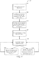
- the depth sensor 100 can operate in a second depth sensing mode by executing a group of common operation steps and one or more dummy operation steps, as shown in block 670.
- the group of common operation steps could be, for example, Step 1 through Step m, and the dummy operation step could be Step 0, in the table 700 shown in FIG. 7 . This would correspond to operation in the low frame rate, long-range depth sensing mode.
- the group of common operation steps executed in block 660 could be Step m+2 through Step m+n+1, and the dummy operation step could be Step m+n+2, in the table 700 shown in FIG. 7 . This would correspond to operation in the low frame rate, short-range depth sensing mode.
- the depth sensor 100 captures one or more frames of depth information while in the specified depth sensing mode. Once the measurement is complete, the method 600 returns back to block 650 where the depth sensing mode of operation can once again be specified.
- T eye_safe_dummy The long-range measurement is followed at Step 9 by an eye safety delay, which is labeled as T eye_safe_dummy in FIG. 9 .
- This delay can prevent the triggering of eye-safety circuits in the depth sensor 100 such that the light source of the depth sensor is not shut off in the middle of a measurement.
- This delay is another example of a dummy operation step and is discussed further below.
- dummy operation steps which constitute delays may, in some embodiments, be implemented as an intensity sub-frame (including an exposure period and a readout period) followed by an idle period.
- the intensity sub-frame which is captured during a dummy operation step is typically not used to calculate depths.
- the differences between the HDR depth sensing mode as compared to the high frame rate, long-range mode and the high frame rate, short-range mode are the eye safety period at Step 9 in Table 5 and the optional delay at Step 15. These differences can be implemented by appropriate dummy operation frames, as discussed herein.
- the eye safety period can be implemented by the eye safe dummy operation step shown at Step m+1 in the programming scheme 700 shown in FIG. 7 .
- the optional delay at Step 15 in Table 5 can be implemented using the dummy operation at Step m+n+2 of the programming scheme 700 shown in FIG. 7 .
- switching the sensor between the first and second modes of operation may not require any additional act to store an operation step in the sensor memory.
- the first mode of operation can comprise executing at least the common operation steps at a first rate
- the second mode of operation can comprise performing the common operation steps and at least one dummy operation step at a second rate which is slower than the first rate
- At least one of the one or more dummy operation steps can comprise a delay.
- providing the sensor with the sequence of common operation steps and the one or more dummy operation steps can comprise storing those operation steps in a sensor memory.
- the first mode of operation can comprise a depth sensing mode with a first frame rate and the second mode of operation can comprise a depth sensing mode with a second frame rate which is slower than the first frame rate.
- the system can be integrated in a virtual reality, augmented reality, or mixed reality display system.
- the system can further comprise an arbiter to receive requests to operate the sensor in the first mode or the second mode, and the arbiter can be configured to schedule and prioritize the requests.
- the system can further comprise the sensor.
- the arbiter can be configured to assign the first priority based on a priority of a first application requesting the first type of depth measurement, and to assign the second priority based on a priority of a second application requesting the second type of depth measurement.
- the depth sensor can comprise a time-of-flight camera.
- the first depth sensing mode of operation can correspond to a first distance range of measurements and the second depth sensing mode of operation can correspond to a second distance range of measurements which is different from the first distance range of measurements.
- the first depth sensing mode of operation can correspond to a first frame rate and the second depth sensing mode of operation can correspond to a second frame rate which is slower than the first frame rate.
- the method can further comprise providing depth information from the depth sensor to a virtual reality, augmented reality, or mixed reality display system.
- a system comprises: a processor configured to execute a method comprising: performing a configuration operation for a depth sensor, the configuration operation comprising storing a first sequence of operation steps which define a first depth sensing mode of operation in a memory of the depth sensor, and storing a second sequence of operation steps which define a second depth sensing mode of operation in the memory of the depth sensor; receiving a first request for depth measurements according to the first depth sensing mode of operation; in response to the first request, operating the depth sensor in the first mode of operation by causing it to execute the first sequence of operation steps; receiving a second request for depth measurements according to the second depth sensing mode of operation; and in response to the second request, and without performing an additional configuration operation, operating the depth sensor in the second mode of operation by causing it to execute the second sequence of operation steps.
- the system can be integrated in a virtual, augmented, or mixed reality display system.
- a non-transitory computer-readable medium comprises code which, when read by a computing device, causes the computing device to perform a method comprising: providing the sensor with a sequence of common operation steps which are included in both a first sequence of operation steps which define a first mode of operation and a second sequence of operation steps which define a second mode of operation; providing the sensor with one or more dummy operation steps which relate to the difference between the first mode of operation and the second mode of operation; operating the sensor in the first mode of operation by causing it to execute at least the common operation steps; and operating the sensor in the second mode of operation by causing it to execute the common operation steps and at least one dummy operation step.
- the first mode of operation can comprise executing at least the common operation steps at a first rate
- the second mode of operation can comprise performing the common operation steps and at least one dummy operation step at a second rate which is slower than the first rate
- At least one of the one or more dummy operation steps can comprise a delay.
- the first depth sensing mode of operation can correspond to a first distance range of measurements and the second depth sensing mode of operation can correspond to a second distance range of measurements which is different from the first distance range of measurements.
Landscapes
- Engineering & Computer Science (AREA)
- Multimedia (AREA)
- Signal Processing (AREA)
- Theoretical Computer Science (AREA)
- Physics & Mathematics (AREA)
- General Physics & Mathematics (AREA)
- General Engineering & Computer Science (AREA)
- Human Computer Interaction (AREA)
- Computing Systems (AREA)
- Electromagnetism (AREA)
- Radar, Positioning & Navigation (AREA)
- Remote Sensing (AREA)
- Computer Networks & Wireless Communication (AREA)
- Studio Devices (AREA)
- Length Measuring Devices By Optical Means (AREA)
- Optical Radar Systems And Details Thereof (AREA)
- Measurement Of Optical Distance (AREA)
- Testing Or Calibration Of Command Recording Devices (AREA)
- User Interface Of Digital Computer (AREA)
- Holo Graphy (AREA)
- Radar Systems Or Details Thereof (AREA)
- Processing Or Creating Images (AREA)
- Image Processing (AREA)
Priority Applications (1)
| Application Number | Priority Date | Filing Date | Title |
|---|---|---|---|
| EP24215265.0A EP4489393A3 (de) | 2017-03-21 | 2018-03-19 | Tiefenmesstechniken für systeme der virtuellen, erweiterten und gemischten realität |
Applications Claiming Priority (3)
| Application Number | Priority Date | Filing Date | Title |
|---|---|---|---|
| US201762474503P | 2017-03-21 | 2017-03-21 | |
| EP18771170.0A EP3603055B1 (de) | 2017-03-21 | 2018-03-19 | Tiefenerfassungsverfahren für systeme der virtuellen, erweiterten und gemischten realität |
| PCT/US2018/023179 WO2018175344A1 (en) | 2017-03-21 | 2018-03-19 | Depth sensing techniques for virtual, augmented, and mixed reality systems |
Related Parent Applications (1)
| Application Number | Title | Priority Date | Filing Date |
|---|---|---|---|
| EP18771170.0A Division EP3603055B1 (de) | 2017-03-21 | 2018-03-19 | Tiefenerfassungsverfahren für systeme der virtuellen, erweiterten und gemischten realität |
Related Child Applications (1)
| Application Number | Title | Priority Date | Filing Date |
|---|---|---|---|
| EP24215265.0A Division EP4489393A3 (de) | 2017-03-21 | 2018-03-19 | Tiefenmesstechniken für systeme der virtuellen, erweiterten und gemischten realität |
Publications (3)
| Publication Number | Publication Date |
|---|---|
| EP4020982A2 true EP4020982A2 (de) | 2022-06-29 |
| EP4020982A3 EP4020982A3 (de) | 2022-09-21 |
| EP4020982B1 EP4020982B1 (de) | 2024-12-04 |
Family
ID=63583181
Family Applications (3)
| Application Number | Title | Priority Date | Filing Date |
|---|---|---|---|
| EP22157426.2A Active EP4020982B1 (de) | 2017-03-21 | 2018-03-19 | Tiefenerfassungsverfahren für systeme der virtuellen, erweiterten und gemischten realität |
| EP24215265.0A Pending EP4489393A3 (de) | 2017-03-21 | 2018-03-19 | Tiefenmesstechniken für systeme der virtuellen, erweiterten und gemischten realität |
| EP18771170.0A Active EP3603055B1 (de) | 2017-03-21 | 2018-03-19 | Tiefenerfassungsverfahren für systeme der virtuellen, erweiterten und gemischten realität |
Family Applications After (2)
| Application Number | Title | Priority Date | Filing Date |
|---|---|---|---|
| EP24215265.0A Pending EP4489393A3 (de) | 2017-03-21 | 2018-03-19 | Tiefenmesstechniken für systeme der virtuellen, erweiterten und gemischten realität |
| EP18771170.0A Active EP3603055B1 (de) | 2017-03-21 | 2018-03-19 | Tiefenerfassungsverfahren für systeme der virtuellen, erweiterten und gemischten realität |
Country Status (9)
| Country | Link |
|---|---|
| US (5) | US10455153B2 (de) |
| EP (3) | EP4020982B1 (de) |
| JP (5) | JP7198766B2 (de) |
| KR (2) | KR102493992B1 (de) |
| CN (3) | CN118819301A (de) |
| AU (1) | AU2018237067B2 (de) |
| CA (1) | CA3055572C (de) |
| IL (3) | IL269008B2 (de) |
| WO (1) | WO2018175344A1 (de) |
Cited By (1)
| Publication number | Priority date | Publication date | Assignee | Title |
|---|---|---|---|---|
| EP4489393A2 (de) | 2017-03-21 | 2025-01-08 | Magic Leap, Inc. | Tiefenmesstechniken für systeme der virtuellen, erweiterten und gemischten realität |
Families Citing this family (26)
| Publication number | Priority date | Publication date | Assignee | Title |
|---|---|---|---|---|
| US11619814B1 (en) * | 2018-06-04 | 2023-04-04 | Meta Platforms Technologies, Llc | Apparatus, system, and method for improving digital head-mounted displays |
| US11902677B2 (en) | 2018-11-12 | 2024-02-13 | Magic Leap, Inc. | Patch tracking image sensor |
| US11809613B2 (en) | 2018-11-12 | 2023-11-07 | Magic Leap, Inc. | Event-based camera with high-resolution frame output |
| WO2020101891A1 (en) | 2018-11-12 | 2020-05-22 | Magic Leap, Inc. | Depth based dynamic vision sensor |
| WO2020102110A1 (en) | 2018-11-13 | 2020-05-22 | Magic Leap, Inc. | Event-based ir camera |
| US10861165B2 (en) * | 2019-01-11 | 2020-12-08 | Microsoft Technology Licensing, Llc | Subject tracking with aliased time-of-flight data |
| EP3914997A4 (de) | 2019-01-25 | 2022-10-12 | Magic Leap, Inc. | Augenverfolgung unter verwendung von bildern mit verschiedenen belichtungszeiten |
| EP3922011A4 (de) | 2019-02-07 | 2022-10-26 | Magic Leap, Inc. | Leichte realitätsübergreifende vorrichtung mit geringer leistungsaufnahme und mit hoher zeitlicher auflösung |
| JP7720783B2 (ja) | 2019-02-07 | 2025-08-08 | マジック リープ, インコーポレイテッド | 受動深度抽出を伴う軽量のクロスリアリティデバイス |
| EP3973347B1 (de) | 2019-05-20 | 2025-03-26 | Magic Leap, Inc. | Systeme und techniken zur schätzung der augenstellung |
| WO2021004944A1 (en) * | 2019-07-05 | 2021-01-14 | Sony Semiconductor Solutions Corporation | Time-of-flight sensing circuitry with different imaging modes and method for operating such a time-of-flight sensing circuitry |
| US20220229189A1 (en) * | 2019-07-05 | 2022-07-21 | Sony Semiconductor Solutions Corporation | Time-of-flight sensor and system |
| WO2021004795A1 (en) * | 2019-07-05 | 2021-01-14 | Sony Semiconductor Solutions Corporation | Time-of-flight sensing circuitry and method for operating a time-of-flight sensing circuitry |
| EP3789771B1 (de) | 2019-09-05 | 2023-01-04 | F. Hoffmann-La Roche AG | Verfahren und system zur lokalisierung eines trägers auf einem labortransportsystem |
| JP7175872B2 (ja) * | 2019-11-14 | 2022-11-21 | 株式会社日立エルジーデータストレージ | 測距装置 |
| US11895412B2 (en) * | 2020-03-10 | 2024-02-06 | Sony Semiconductor Solutions Corporation | Imaging device and imaging method |
| JP7567492B2 (ja) * | 2020-03-18 | 2024-10-16 | 株式会社リコー | 距離計測装置及び距離計測方法 |
| EP4121794A1 (de) | 2020-03-18 | 2023-01-25 | Ricoh Company, Ltd. | Entfernungsmessvorrichtung und entfernungsmessverfahren |
| US12306349B2 (en) | 2020-05-15 | 2025-05-20 | Analog Devices International Unlimited Company | Proximity detection system |
| US12000931B2 (en) | 2020-05-15 | 2024-06-04 | Analog Devices International Unlimited Company | Continuous wave time of flight system |
| KR102817675B1 (ko) | 2020-07-15 | 2025-06-09 | 매직 립, 인코포레이티드 | 비구면 각막 모델을 사용한 눈 추적 |
| JP7596810B2 (ja) * | 2021-01-22 | 2024-12-10 | Toppanホールディングス株式会社 | 距離画像撮像装置及び距離画像撮像方法 |
| WO2024162659A1 (ko) * | 2023-01-31 | 2024-08-08 | 삼성전자 주식회사 | 이미지 센서, 이미지 센서를 포함하는 전자 장치 및 그 동작 방법 |
| WO2024167310A1 (ko) * | 2023-02-07 | 2024-08-15 | 삼성전자 주식회사 | Tof 센서의 소모 전류를 감소하는 방법 및 이를 지원하는 전자 장치 |
| EP4726676A1 (de) * | 2023-06-08 | 2026-04-15 | LG Electronics Inc. | Signalverarbeitungsvorrichtung und anzeigevorrichtung damit für fahrzeuge |
| US12505562B2 (en) * | 2023-08-04 | 2025-12-23 | Himax Technologies Limited | Object tracking system and 3D location reporting method |
Family Cites Families (77)
| Publication number | Priority date | Publication date | Assignee | Title |
|---|---|---|---|---|
| US4628312A (en) * | 1983-10-19 | 1986-12-09 | Vega Precision Laboratories, Inc. | Decoding apparatus and method for a position coded pulse communication system |
| JPH053568A (ja) | 1991-06-25 | 1993-01-08 | Canon Inc | ビデオカメラ装置 |
| JPH0553568A (ja) | 1991-08-22 | 1993-03-05 | Seiko Epson Corp | 画像処理装置 |
| US6222525B1 (en) | 1992-03-05 | 2001-04-24 | Brad A. Armstrong | Image controllers with sheet connected sensors |
| US5670988A (en) | 1995-09-05 | 1997-09-23 | Interlink Electronics, Inc. | Trigger operated electronic device |
| JPH1153568A (ja) * | 1997-08-07 | 1999-02-26 | Matsushita Electric Ind Co Ltd | 画像処理装置 |
| JP2001337166A (ja) | 2000-05-26 | 2001-12-07 | Minolta Co Ltd | 3次元入力方法および3次元入力装置 |
| JP2004157061A (ja) | 2002-11-08 | 2004-06-03 | Nikon-Trimble Co Ltd | 距離測定装置 |
| USD514570S1 (en) | 2004-06-24 | 2006-02-07 | Microsoft Corporation | Region of a fingerprint scanning device with an illuminated ring |
| US8696113B2 (en) | 2005-10-07 | 2014-04-15 | Percept Technologies Inc. | Enhanced optical and perceptual digital eyewear |
| US11428937B2 (en) | 2005-10-07 | 2022-08-30 | Percept Technologies | Enhanced optical and perceptual digital eyewear |
| US20070081123A1 (en) | 2005-10-07 | 2007-04-12 | Lewis Scott W | Digital eyewear |
| JP2008183049A (ja) | 2007-01-26 | 2008-08-14 | Matsushita Electric Ind Co Ltd | 撮像装置、カプセル型内視カメラ |
| JP4936528B2 (ja) | 2007-03-28 | 2012-05-23 | 富士フイルム株式会社 | カプセル内視鏡システム、およびカプセル内視鏡システムの作動方法 |
| US7852461B2 (en) * | 2007-11-15 | 2010-12-14 | Microsoft International Holdings B.V. | Dual mode depth imaging |
| JP4826615B2 (ja) | 2008-09-30 | 2011-11-30 | パナソニック電工株式会社 | 車両用周辺監視装置 |
| JP5415434B2 (ja) | 2008-10-02 | 2014-02-12 | 日立オートモティブシステムズ株式会社 | 車両走行に関する情報処理装置 |
| JP2010230366A (ja) | 2009-03-26 | 2010-10-14 | Denso Corp | 障害物検出装置 |
| JP5156695B2 (ja) | 2009-06-25 | 2013-03-06 | 本田技研工業株式会社 | 三次元形状測定システム |
| JP2012053029A (ja) | 2010-08-05 | 2012-03-15 | Ricoh Co Ltd | 測光・測距装置、測光・測距方法及びその測光・測距装置を有する撮像機器 |
| US20120056982A1 (en) | 2010-09-08 | 2012-03-08 | Microsoft Corporation | Depth camera based on structured light and stereo vision |
| US8681255B2 (en) * | 2010-09-28 | 2014-03-25 | Microsoft Corporation | Integrated low power depth camera and projection device |
| US9304319B2 (en) | 2010-11-18 | 2016-04-05 | Microsoft Technology Licensing, Llc | Automatic focus improvement for augmented reality displays |
| US10156722B2 (en) | 2010-12-24 | 2018-12-18 | Magic Leap, Inc. | Methods and systems for displaying stereoscopy with a freeform optical system with addressable focus for virtual and augmented reality |
| NZ706893A (en) | 2010-12-24 | 2017-02-24 | Magic Leap Inc | An ergonomic head mounted display device and optical system |
| GB2502213A (en) | 2010-12-30 | 2013-11-20 | Irobot Corp | Mobile Human Interface Robot |
| JP5330431B2 (ja) * | 2011-03-11 | 2013-10-30 | 富士フイルム株式会社 | 超音波プローブおよび超音波診断装置 |
| CA3035118C (en) | 2011-05-06 | 2022-01-04 | Magic Leap, Inc. | Massive simultaneous remote digital presence world |
| US9317961B2 (en) * | 2011-09-14 | 2016-04-19 | Google Inc. | Prioritizing node requests based on tile distance to reduce perceptual scene time |
| EP2760363A4 (de) | 2011-09-29 | 2015-06-24 | Magic Leap Inc | Taktiler handschuh zur mensch-computer-interaktion |
| RU2017115669A (ru) | 2011-10-28 | 2019-01-28 | Мэджик Лип, Инк. | Система и способ для дополненной и виртуальной реальности |
| KR101869277B1 (ko) * | 2011-11-17 | 2018-06-22 | 삼성전자주식회사 | 화소 회로 및 이를 포함하는 깊이 센서 |
| CN104067316B (zh) | 2011-11-23 | 2017-10-27 | 奇跃公司 | 三维虚拟和增强现实显示系统 |
| JP2013123172A (ja) * | 2011-12-12 | 2013-06-20 | Nikon Corp | 撮像装置およびプログラム |
| JP5912591B2 (ja) | 2012-02-01 | 2016-04-27 | 東京パーツ工業株式会社 | 物体検知装置及び車両用開閉体制御装置 |
| BR112014024941A2 (pt) | 2012-04-05 | 2017-09-19 | Magic Leap Inc | dispositivo de imagem de campo de visão amplo com capacidade de focalização ativa |
| JP5968025B2 (ja) * | 2012-04-11 | 2016-08-10 | キヤノン株式会社 | 撮像装置及び撮像装置の制御方法 |
| US9671566B2 (en) | 2012-06-11 | 2017-06-06 | Magic Leap, Inc. | Planar waveguide apparatus with diffraction element(s) and system employing same |
| AU2013274359B2 (en) | 2012-06-11 | 2017-05-25 | Magic Leap, Inc. | Multiple depth plane three-dimensional display using a wave guide reflector array projector |
| JP2015534108A (ja) | 2012-09-11 | 2015-11-26 | マジック リープ, インコーポレイテッド | 人間工学的な頭部搭載型ディスプレイデバイスおよび光学システム |
| US9432916B2 (en) | 2012-12-27 | 2016-08-30 | Intel Corporation | Situation aware sensor power management |
| IL301489B2 (en) | 2013-01-15 | 2024-08-01 | Magic Leap Inc | A system for scanning electromagnetic imaging radiation |
| US9407837B2 (en) * | 2013-02-28 | 2016-08-02 | Google Inc. | Depth sensor using modulated light projector and image sensor with color and IR sensing |
| US9142019B2 (en) * | 2013-02-28 | 2015-09-22 | Google Technology Holdings LLC | System for 2D/3D spatial feature processing |
| KR20230044041A (ko) * | 2013-03-11 | 2023-03-31 | 매직 립, 인코포레이티드 | 증강 및 가상 현실을 위한 시스템 및 방법 |
| CN105229719B (zh) | 2013-03-15 | 2018-04-27 | 奇跃公司 | 显示系统和方法 |
| US10262462B2 (en) | 2014-04-18 | 2019-04-16 | Magic Leap, Inc. | Systems and methods for augmented and virtual reality |
| US9874749B2 (en) | 2013-11-27 | 2018-01-23 | Magic Leap, Inc. | Virtual and augmented reality systems and methods |
| WO2015005754A1 (ko) | 2013-07-12 | 2015-01-15 | 삼성전자 주식회사 | 뷰 합성 예측을 이용한 인터 레이어 비디오 복호화 방법 및 그 장치 뷰 합성 예측을 이용한 인터 레이어 비디오 부호화 방법 및 장치 |
| EP3058418B1 (de) | 2013-10-16 | 2023-10-04 | Magic Leap, Inc. | Kopfhörer für virtuelle oder erweiterte realität mit einstellbarem zwischenpupillenabstand |
| US9857591B2 (en) | 2014-05-30 | 2018-01-02 | Magic Leap, Inc. | Methods and system for creating focal planes in virtual and augmented reality |
| KR102651578B1 (ko) | 2013-11-27 | 2024-03-25 | 매직 립, 인코포레이티드 | 가상 및 증강 현실 시스템들 및 방법들 |
| NZ722903A (en) | 2014-01-31 | 2020-05-29 | Magic Leap Inc | Multi-focal display system and method |
| KR102177133B1 (ko) * | 2014-01-31 | 2020-11-10 | 매직 립, 인코포레이티드 | 멀티-포컬 디스플레이 시스템 및 방법 |
| US10203762B2 (en) | 2014-03-11 | 2019-02-12 | Magic Leap, Inc. | Methods and systems for creating virtual and augmented reality |
| US9389069B2 (en) | 2014-03-26 | 2016-07-12 | Alces Technology, Inc. | Compact 3D depth capture systems |
| EP3140779A4 (de) | 2014-05-09 | 2017-11-29 | Google LLC | Systeme und verfahren zur verwendung von augensignalen mit sicherer mobilkommunikation |
| USD759657S1 (en) | 2014-05-19 | 2016-06-21 | Microsoft Corporation | Connector with illumination region |
| NZ764905A (en) | 2014-05-30 | 2022-05-27 | Magic Leap Inc | Methods and systems for generating virtual content display with a virtual or augmented reality apparatus |
| USD752529S1 (en) | 2014-06-09 | 2016-03-29 | Comcast Cable Communications, Llc | Electronic housing with illuminated region |
| WO2016004499A1 (en) * | 2014-07-08 | 2016-01-14 | Grigori Broudno | High efficiency spark plug |
| US20160140760A1 (en) * | 2014-11-13 | 2016-05-19 | Upton Beall Bowden | Adapting a display on a transparent electronic display |
| US9552816B2 (en) * | 2014-12-19 | 2017-01-24 | Amazon Technologies, Inc. | Application focus in speech-based systems |
| WO2016151918A1 (ja) | 2015-03-26 | 2016-09-29 | 富士フイルム株式会社 | 距離画像取得装置及び距離画像取得方法 |
| US9967535B2 (en) | 2015-04-17 | 2018-05-08 | Light Labs Inc. | Methods and apparatus for reducing noise in images |
| JP2016213786A (ja) * | 2015-05-13 | 2016-12-15 | パナソニックIpマネジメント株式会社 | カメラ装置 |
| USD758367S1 (en) | 2015-05-14 | 2016-06-07 | Magic Leap, Inc. | Virtual reality headset |
| US9683834B2 (en) | 2015-05-27 | 2017-06-20 | Intel Corporation | Adaptable depth sensing system |
| CN105357511B (zh) * | 2015-12-08 | 2018-05-15 | 上海图漾信息科技有限公司 | 深度数据检测系统 |
| CN107533136B (zh) | 2015-06-24 | 2020-08-25 | 株式会社村田制作所 | 距离传感器 |
| US9887537B2 (en) | 2015-06-30 | 2018-02-06 | Microsoft Technology Licensing, Llc | Analog limit on digitally set pulse widths |
| US10341633B2 (en) * | 2015-11-20 | 2019-07-02 | Qualcomm Incorporated | Systems and methods for correcting erroneous depth information |
| US10477157B1 (en) * | 2016-03-02 | 2019-11-12 | Meta View, Inc. | Apparatuses, methods and systems for a sensor array adapted for vision computing |
| USD805734S1 (en) | 2016-03-04 | 2017-12-26 | Nike, Inc. | Shirt |
| USD794288S1 (en) | 2016-03-11 | 2017-08-15 | Nike, Inc. | Shoe with illuminable sole light sequence |
| US10110840B2 (en) * | 2016-10-25 | 2018-10-23 | Semiconductor Components Industries, Llc | Image sensor pixels with overflow capabilities |
| IL269008B2 (en) | 2017-03-21 | 2023-10-01 | Magic Leap Inc | Depth sensing techniques for virtual, augmented and mixed reality systems |
-
2018
- 2018-03-19 IL IL269008A patent/IL269008B2/en unknown
- 2018-03-19 CN CN202411028927.6A patent/CN118819301A/zh active Pending
- 2018-03-19 CN CN201880019671.9A patent/CN110431841B/zh active Active
- 2018-03-19 IL IL302172A patent/IL302172B2/en unknown
- 2018-03-19 EP EP22157426.2A patent/EP4020982B1/de active Active
- 2018-03-19 KR KR1020197030693A patent/KR102493992B1/ko active Active
- 2018-03-19 WO PCT/US2018/023179 patent/WO2018175344A1/en not_active Ceased
- 2018-03-19 KR KR1020237003052A patent/KR102527329B1/ko active Active
- 2018-03-19 CN CN202110857359.0A patent/CN113568508B/zh active Active
- 2018-03-19 CA CA3055572A patent/CA3055572C/en active Active
- 2018-03-19 US US15/925,577 patent/US10455153B2/en active Active
- 2018-03-19 AU AU2018237067A patent/AU2018237067B2/en active Active
- 2018-03-19 EP EP24215265.0A patent/EP4489393A3/de active Pending
- 2018-03-19 EP EP18771170.0A patent/EP3603055B1/de active Active
- 2018-03-19 IL IL308454A patent/IL308454A/en unknown
- 2018-03-19 JP JP2019548327A patent/JP7198766B2/ja active Active
-
2019
- 2019-09-17 US US16/573,891 patent/US11303809B2/en active Active
-
2021
- 2021-03-10 JP JP2021038206A patent/JP7198850B2/ja active Active
-
2022
- 2022-03-09 US US17/690,956 patent/US11778318B2/en active Active
- 2022-11-18 JP JP2022184776A patent/JP7535089B2/ja active Active
-
2023
- 2023-08-22 US US18/453,762 patent/US12192623B2/en active Active
- 2023-11-21 JP JP2023197268A patent/JP7723720B2/ja active Active
-
2024
- 2024-10-25 JP JP2024188159A patent/JP7850220B2/ja active Active
- 2024-11-24 US US18/957,796 patent/US20250088739A1/en active Pending
Cited By (1)
| Publication number | Priority date | Publication date | Assignee | Title |
|---|---|---|---|---|
| EP4489393A2 (de) | 2017-03-21 | 2025-01-08 | Magic Leap, Inc. | Tiefenmesstechniken für systeme der virtuellen, erweiterten und gemischten realität |
Also Published As
Similar Documents
| Publication | Publication Date | Title |
|---|---|---|
| US12192623B2 (en) | Depth sensing techniques for virtual, augmented, and mixed reality systems | |
| US8548270B2 (en) | Time-of-flight depth imaging | |
| KR101879478B1 (ko) | 레이저 깊이 지도 레인지를 확대하는 방법 | |
| CN112189147B (zh) | 一种飞行时间ToF相机和一种ToF方法 |
Legal Events
| Date | Code | Title | Description |
|---|---|---|---|
| PUAI | Public reference made under article 153(3) epc to a published international application that has entered the european phase |
Free format text: ORIGINAL CODE: 0009012 |
|
| STAA | Information on the status of an ep patent application or granted ep patent |
Free format text: STATUS: THE APPLICATION HAS BEEN PUBLISHED |
|
| AC | Divisional application: reference to earlier application |
Ref document number: 3603055 Country of ref document: EP Kind code of ref document: P |
|
| AK | Designated contracting states |
Kind code of ref document: A2 Designated state(s): AL AT BE BG CH CY CZ DE DK EE ES FI FR GB GR HR HU IE IS IT LI LT LU LV MC MK MT NL NO PL PT RO RS SE SI SK SM TR |
|
| PUAL | Search report despatched |
Free format text: ORIGINAL CODE: 0009013 |
|
| AK | Designated contracting states |
Kind code of ref document: A3 Designated state(s): AL AT BE BG CH CY CZ DE DK EE ES FI FR GB GR HR HU IE IS IT LI LT LU LV MC MK MT NL NO PL PT RO RS SE SI SK SM TR |
|
| RIC1 | Information provided on ipc code assigned before grant |
Ipc: H04N 13/20 20180101ALI20220815BHEP Ipc: H04N 13/268 20180101ALI20220815BHEP Ipc: H04N 13/128 20180101AFI20220815BHEP |
|
| STAA | Information on the status of an ep patent application or granted ep patent |
Free format text: STATUS: REQUEST FOR EXAMINATION WAS MADE |
|
| 17P | Request for examination filed |
Effective date: 20230313 |
|
| RBV | Designated contracting states (corrected) |
Designated state(s): AL AT BE BG CH CY CZ DE DK EE ES FI FR GB GR HR HU IE IS IT LI LT LU LV MC MK MT NL NO PL PT RO RS SE SI SK SM TR |
|
| P01 | Opt-out of the competence of the unified patent court (upc) registered |
Effective date: 20230622 |
|
| GRAP | Despatch of communication of intention to grant a patent |
Free format text: ORIGINAL CODE: EPIDOSNIGR1 |
|
| STAA | Information on the status of an ep patent application or granted ep patent |
Free format text: STATUS: GRANT OF PATENT IS INTENDED |
|
| INTG | Intention to grant announced |
Effective date: 20240626 |
|
| GRAS | Grant fee paid |
Free format text: ORIGINAL CODE: EPIDOSNIGR3 |
|
| GRAA | (expected) grant |
Free format text: ORIGINAL CODE: 0009210 |
|
| STAA | Information on the status of an ep patent application or granted ep patent |
Free format text: STATUS: THE PATENT HAS BEEN GRANTED |
|
| AC | Divisional application: reference to earlier application |
Ref document number: 3603055 Country of ref document: EP Kind code of ref document: P |
|
| AK | Designated contracting states |
Kind code of ref document: B1 Designated state(s): AL AT BE BG CH CY CZ DE DK EE ES FI FR GB GR HR HU IE IS IT LI LT LU LV MC MK MT NL NO PL PT RO RS SE SI SK SM TR |
|
| REG | Reference to a national code |
Ref country code: CH Ref legal event code: EP |
|
| REG | Reference to a national code |
Ref country code: NL Ref legal event code: FP |
|
| REG | Reference to a national code |
Ref country code: DE Ref legal event code: R096 Ref document number: 602018077427 Country of ref document: DE |
|
| REG | Reference to a national code |
Ref country code: IE Ref legal event code: FG4D |
|
| REG | Reference to a national code |
Ref country code: LT Ref legal event code: MG9D |
|
| PG25 | Lapsed in a contracting state [announced via postgrant information from national office to epo] |
Ref country code: HR Free format text: LAPSE BECAUSE OF FAILURE TO SUBMIT A TRANSLATION OF THE DESCRIPTION OR TO PAY THE FEE WITHIN THE PRESCRIBED TIME-LIMIT Effective date: 20241204 |
|
| PG25 | Lapsed in a contracting state [announced via postgrant information from national office to epo] |
Ref country code: FI Free format text: LAPSE BECAUSE OF FAILURE TO SUBMIT A TRANSLATION OF THE DESCRIPTION OR TO PAY THE FEE WITHIN THE PRESCRIBED TIME-LIMIT Effective date: 20241204 |
|
| PG25 | Lapsed in a contracting state [announced via postgrant information from national office to epo] |
Ref country code: BG Free format text: LAPSE BECAUSE OF FAILURE TO SUBMIT A TRANSLATION OF THE DESCRIPTION OR TO PAY THE FEE WITHIN THE PRESCRIBED TIME-LIMIT Effective date: 20241204 |
|
| PG25 | Lapsed in a contracting state [announced via postgrant information from national office to epo] |
Ref country code: ES Free format text: LAPSE BECAUSE OF FAILURE TO SUBMIT A TRANSLATION OF THE DESCRIPTION OR TO PAY THE FEE WITHIN THE PRESCRIBED TIME-LIMIT Effective date: 20241204 |
|
| PG25 | Lapsed in a contracting state [announced via postgrant information from national office to epo] |
Ref country code: NO Free format text: LAPSE BECAUSE OF FAILURE TO SUBMIT A TRANSLATION OF THE DESCRIPTION OR TO PAY THE FEE WITHIN THE PRESCRIBED TIME-LIMIT Effective date: 20250304 |
|
| PG25 | Lapsed in a contracting state [announced via postgrant information from national office to epo] |
Ref country code: LV Free format text: LAPSE BECAUSE OF FAILURE TO SUBMIT A TRANSLATION OF THE DESCRIPTION OR TO PAY THE FEE WITHIN THE PRESCRIBED TIME-LIMIT Effective date: 20241204 Ref country code: GR Free format text: LAPSE BECAUSE OF FAILURE TO SUBMIT A TRANSLATION OF THE DESCRIPTION OR TO PAY THE FEE WITHIN THE PRESCRIBED TIME-LIMIT Effective date: 20250305 |
|
| PG25 | Lapsed in a contracting state [announced via postgrant information from national office to epo] |
Ref country code: RS Free format text: LAPSE BECAUSE OF FAILURE TO SUBMIT A TRANSLATION OF THE DESCRIPTION OR TO PAY THE FEE WITHIN THE PRESCRIBED TIME-LIMIT Effective date: 20250304 |
|
| REG | Reference to a national code |
Ref country code: AT Ref legal event code: MK05 Ref document number: 1749395 Country of ref document: AT Kind code of ref document: T Effective date: 20241204 |
|
| PG25 | Lapsed in a contracting state [announced via postgrant information from national office to epo] |
Ref country code: SM Free format text: LAPSE BECAUSE OF FAILURE TO SUBMIT A TRANSLATION OF THE DESCRIPTION OR TO PAY THE FEE WITHIN THE PRESCRIBED TIME-LIMIT Effective date: 20241204 |
|
| PG25 | Lapsed in a contracting state [announced via postgrant information from national office to epo] |
Ref country code: PL Free format text: LAPSE BECAUSE OF FAILURE TO SUBMIT A TRANSLATION OF THE DESCRIPTION OR TO PAY THE FEE WITHIN THE PRESCRIBED TIME-LIMIT Effective date: 20241204 |
|
| PG25 | Lapsed in a contracting state [announced via postgrant information from national office to epo] |
Ref country code: IS Free format text: LAPSE BECAUSE OF FAILURE TO SUBMIT A TRANSLATION OF THE DESCRIPTION OR TO PAY THE FEE WITHIN THE PRESCRIBED TIME-LIMIT Effective date: 20250404 |
|
| PG25 | Lapsed in a contracting state [announced via postgrant information from national office to epo] |
Ref country code: PT Free format text: LAPSE BECAUSE OF FAILURE TO SUBMIT A TRANSLATION OF THE DESCRIPTION OR TO PAY THE FEE WITHIN THE PRESCRIBED TIME-LIMIT Effective date: 20250404 |
|
| PG25 | Lapsed in a contracting state [announced via postgrant information from national office to epo] |
Ref country code: EE Free format text: LAPSE BECAUSE OF FAILURE TO SUBMIT A TRANSLATION OF THE DESCRIPTION OR TO PAY THE FEE WITHIN THE PRESCRIBED TIME-LIMIT Effective date: 20241204 |
|
| PG25 | Lapsed in a contracting state [announced via postgrant information from national office to epo] |
Ref country code: AT Free format text: LAPSE BECAUSE OF FAILURE TO SUBMIT A TRANSLATION OF THE DESCRIPTION OR TO PAY THE FEE WITHIN THE PRESCRIBED TIME-LIMIT Effective date: 20241204 Ref country code: RO Free format text: LAPSE BECAUSE OF FAILURE TO SUBMIT A TRANSLATION OF THE DESCRIPTION OR TO PAY THE FEE WITHIN THE PRESCRIBED TIME-LIMIT Effective date: 20241204 |
|
| PG25 | Lapsed in a contracting state [announced via postgrant information from national office to epo] |
Ref country code: SK Free format text: LAPSE BECAUSE OF FAILURE TO SUBMIT A TRANSLATION OF THE DESCRIPTION OR TO PAY THE FEE WITHIN THE PRESCRIBED TIME-LIMIT Effective date: 20241204 |
|
| PG25 | Lapsed in a contracting state [announced via postgrant information from national office to epo] |
Ref country code: CZ Free format text: LAPSE BECAUSE OF FAILURE TO SUBMIT A TRANSLATION OF THE DESCRIPTION OR TO PAY THE FEE WITHIN THE PRESCRIBED TIME-LIMIT Effective date: 20241204 |
|
| PG25 | Lapsed in a contracting state [announced via postgrant information from national office to epo] |
Ref country code: IT Free format text: LAPSE BECAUSE OF FAILURE TO SUBMIT A TRANSLATION OF THE DESCRIPTION OR TO PAY THE FEE WITHIN THE PRESCRIBED TIME-LIMIT Effective date: 20241204 |
|
| REG | Reference to a national code |
Ref country code: DE Ref legal event code: R097 Ref document number: 602018077427 Country of ref document: DE |
|
| PG25 | Lapsed in a contracting state [announced via postgrant information from national office to epo] |
Ref country code: SE Free format text: LAPSE BECAUSE OF FAILURE TO SUBMIT A TRANSLATION OF THE DESCRIPTION OR TO PAY THE FEE WITHIN THE PRESCRIBED TIME-LIMIT Effective date: 20241204 |
|
| PG25 | Lapsed in a contracting state [announced via postgrant information from national office to epo] |
Ref country code: DK Free format text: LAPSE BECAUSE OF FAILURE TO SUBMIT A TRANSLATION OF THE DESCRIPTION OR TO PAY THE FEE WITHIN THE PRESCRIBED TIME-LIMIT Effective date: 20241204 |
|
| PLBE | No opposition filed within time limit |
Free format text: ORIGINAL CODE: 0009261 |
|
| STAA | Information on the status of an ep patent application or granted ep patent |
Free format text: STATUS: NO OPPOSITION FILED WITHIN TIME LIMIT |
|
| PG25 | Lapsed in a contracting state [announced via postgrant information from national office to epo] |
Ref country code: MC Free format text: LAPSE BECAUSE OF FAILURE TO SUBMIT A TRANSLATION OF THE DESCRIPTION OR TO PAY THE FEE WITHIN THE PRESCRIBED TIME-LIMIT Effective date: 20241204 |
|
| REG | Reference to a national code |
Ref country code: CH Ref legal event code: L10 Free format text: ST27 STATUS EVENT CODE: U-0-0-L10-L00 (AS PROVIDED BY THE NATIONAL OFFICE) Effective date: 20251015 |
|
| REG | Reference to a national code |
Ref country code: CH Ref legal event code: H13 Free format text: ST27 STATUS EVENT CODE: U-0-0-H10-H13 (AS PROVIDED BY THE NATIONAL OFFICE) Effective date: 20251024 |
|
| 26N | No opposition filed |
Effective date: 20250905 |
|
| PG25 | Lapsed in a contracting state [announced via postgrant information from national office to epo] |
Ref country code: LU Free format text: LAPSE BECAUSE OF NON-PAYMENT OF DUE FEES Effective date: 20250319 |
|
| PG25 | Lapsed in a contracting state [announced via postgrant information from national office to epo] |
Ref country code: CH Free format text: LAPSE BECAUSE OF NON-PAYMENT OF DUE FEES Effective date: 20250331 |
|
| PG25 | Lapsed in a contracting state [announced via postgrant information from national office to epo] |
Ref country code: IE Free format text: LAPSE BECAUSE OF NON-PAYMENT OF DUE FEES Effective date: 20250319 |
|
| PGFP | Annual fee paid to national office [announced via postgrant information from national office to epo] |
Ref country code: NL Payment date: 20260219 Year of fee payment: 9 |
|
| PGFP | Annual fee paid to national office [announced via postgrant information from national office to epo] |
Ref country code: GB Payment date: 20260220 Year of fee payment: 9 |
|
| PGFP | Annual fee paid to national office [announced via postgrant information from national office to epo] |
Ref country code: DE Payment date: 20260219 Year of fee payment: 9 |
|
| PGFP | Annual fee paid to national office [announced via postgrant information from national office to epo] |
Ref country code: BE Payment date: 20260219 Year of fee payment: 9 |
|
| PGFP | Annual fee paid to national office [announced via postgrant information from national office to epo] |
Ref country code: FR Payment date: 20260220 Year of fee payment: 9 |