EP3973347B1 - Systeme und techniken zur schätzung der augenstellung - Google Patents
Systeme und techniken zur schätzung der augenstellung Download PDFInfo
- Publication number
- EP3973347B1 EP3973347B1 EP20809425.0A EP20809425A EP3973347B1 EP 3973347 B1 EP3973347 B1 EP 3973347B1 EP 20809425 A EP20809425 A EP 20809425A EP 3973347 B1 EP3973347 B1 EP 3973347B1
- Authority
- EP
- European Patent Office
- Prior art keywords
- eye
- user
- glint
- image
- images
- Prior art date
- Legal status (The legal status is an assumption and is not a legal conclusion. Google has not performed a legal analysis and makes no representation as to the accuracy of the status listed.)
- Active
Links
Images


Classifications
-
- G—PHYSICS
- G06—COMPUTING OR CALCULATING; COUNTING
- G06F—ELECTRIC DIGITAL DATA PROCESSING
- G06F3/00—Input arrangements for transferring data to be processed into a form capable of being handled by the computer; Output arrangements for transferring data from processing unit to output unit, e.g. interface arrangements
- G06F3/01—Input arrangements or combined input and output arrangements for interaction between user and computer
- G06F3/011—Arrangements for interaction with the human body, e.g. for user immersion in virtual reality
- G06F3/013—Eye tracking input arrangements
-
- G—PHYSICS
- G06—COMPUTING OR CALCULATING; COUNTING
- G06F—ELECTRIC DIGITAL DATA PROCESSING
- G06F3/00—Input arrangements for transferring data to be processed into a form capable of being handled by the computer; Output arrangements for transferring data from processing unit to output unit, e.g. interface arrangements
- G06F3/01—Input arrangements or combined input and output arrangements for interaction between user and computer
- G06F3/011—Arrangements for interaction with the human body, e.g. for user immersion in virtual reality
- G06F3/012—Head tracking input arrangements
-
- G—PHYSICS
- G06—COMPUTING OR CALCULATING; COUNTING
- G06T—IMAGE DATA PROCESSING OR GENERATION, IN GENERAL
- G06T7/00—Image analysis
- G06T7/70—Determining position or orientation of objects or cameras
- G06T7/73—Determining position or orientation of objects or cameras using feature-based methods
-
- G—PHYSICS
- G06—COMPUTING OR CALCULATING; COUNTING
- G06T—IMAGE DATA PROCESSING OR GENERATION, IN GENERAL
- G06T7/00—Image analysis
- G06T7/70—Determining position or orientation of objects or cameras
- G06T7/77—Determining position or orientation of objects or cameras using statistical methods
-
- G—PHYSICS
- G06—COMPUTING OR CALCULATING; COUNTING
- G06T—IMAGE DATA PROCESSING OR GENERATION, IN GENERAL
- G06T2207/00—Indexing scheme for image analysis or image enhancement
- G06T2207/10—Image acquisition modality
- G06T2207/10048—Infrared image
-
- G—PHYSICS
- G06—COMPUTING OR CALCULATING; COUNTING
- G06T—IMAGE DATA PROCESSING OR GENERATION, IN GENERAL
- G06T2207/00—Indexing scheme for image analysis or image enhancement
- G06T2207/10—Image acquisition modality
- G06T2207/10141—Special mode during image acquisition
- G06T2207/10152—Varying illumination
-
- G—PHYSICS
- G06—COMPUTING OR CALCULATING; COUNTING
- G06T—IMAGE DATA PROCESSING OR GENERATION, IN GENERAL
- G06T2207/00—Indexing scheme for image analysis or image enhancement
- G06T2207/30—Subject of image; Context of image processing
- G06T2207/30004—Biomedical image processing
- G06T2207/30041—Eye; Retina; Ophthalmic
-
- G—PHYSICS
- G06—COMPUTING OR CALCULATING; COUNTING
- G06T—IMAGE DATA PROCESSING OR GENERATION, IN GENERAL
- G06T2207/00—Indexing scheme for image analysis or image enhancement
- G06T2207/30—Subject of image; Context of image processing
- G06T2207/30196—Human being; Person
-
- G—PHYSICS
- G06—COMPUTING OR CALCULATING; COUNTING
- G06T—IMAGE DATA PROCESSING OR GENERATION, IN GENERAL
- G06T2207/00—Indexing scheme for image analysis or image enhancement
- G06T2207/30—Subject of image; Context of image processing
- G06T2207/30196—Human being; Person
- G06T2207/30201—Face
Definitions
- the present disclosure relates to display systems, virtual reality, and augmented reality imaging and visualization systems and, more particularly, to techniques for tracking a user's eyes in such systems.
- a virtual reality, or "VR”, scenario typically involves presentation of digital or virtual image information without transparency to other actual real-world visual input
- an augmented reality, or “AR” scenario typically involves presentation of digital or virtual image information as an augmentation to visualization of the actual world around the user
- a mixed reality, or "MR” related to merging real and virtual worlds to produce new environments where physical and virtual objects coexist and interact in real time.
- the human visual perception system is very complex, and producing a VR, AR, or MR technology that facilitates a comfortable, natural-feeling, rich presentation of virtual image elements amongst other virtual or real-world imagery elements is challenging.
- Systems and methods disclosed herein address various challenges related to VR, AR and MR technology.
- US 2019/042842A discloses a head mounted display which comprises an eye tracking system configured to enable eye-tracking using light.
- the eye tracking system implements time-multiplexing by configuring a source assembly comprising a plurality of light sources to project at least a first light pattern towards the user's eye over a first time period, and a second light pattern towards the user's eye over a second time period in accordance with a set of emission instructions.
- a camera assembly is configured to capture images of the user's eye during the first and second time periods in accordance with a set of imaging instructions, the captured images containing one or more glints corresponding to reflections of the first or second light patterns on the cornea of the user's eye. The location of the glints may be used to determine a shape or orientation of the eye.
- US 2019/108383A discloses circuitry of a gaze/eye tracking system which obtains one or more images of a left eye and one or more images a right eye, determines a gaze direction of the left eye based on at least one obtained image of the left eye, determines a gaze direction of the right eye based on at least one obtained image of the right eye, determines a first confidence value based on the one or more obtained images of the left eye, determines a second confidence value based on the one or more obtained images of the right eye, and determines a final gaze direction based at least in part on the first confidence value and the second confidence value.
- the first and second confidence values represent indications of the reliability of the determined gaze directions of the left eye and the right eye, respectively. Corresponding methods and computer-readable media are also provided.
- US 2013/050642A discloses technology which provides for automatic alignment of a see-through near-eye, mixed reality device with an inter-pupillary distance (IPD).
- IPD inter-pupillary distance
- a determination is made as to whether a see-through, near-eye, mixed reality display device is aligned with an IPD of a user. If the display device is not aligned with the IPD, the display device is automatically adjusted.
- the alignment determination is based on determinations of whether an optical axis of each display optical system positioned to be seen through by a respective eye is aligned with a pupil of the respective eye in accordance with an alignment criteria.
- the pupil alignment may be determined based on an arrangement of gaze detection elements for each display optical system including at least one sensor for capturing data of the respective eye and the captured data.
- the captured data may be image data, image and glint data, and glint data only.
- the eye tracking system can include an eye-tracking camera configured to obtain images of the eye at different exposure times or different frame rates. For example, images of the eye taken at a longer exposure time can show iris or pupil features, and images of the eye taken at shorter exposure times (sometimes referred to as glint images) can show peaks of glints reflected from the cornea.
- the shorter exposure glint images may be taken at a higher frame rate (HFR) than the longer exposure images to provide for accurate gaze prediction.
- the shorter exposure glint images can be analyzed to provide glint locations to subpixel accuracy.
- the longer exposure images can be analyzed for pupil center or center of rotation.
- the eye tracking system can predict future gaze direction, which can be used for foveated rendering by a wearable display system, for example, an AR, VR, or MR wearable display system.
- the exposure time of the longer exposure image may be in a range from 200 ⁇ s to 1200 ⁇ s, for example, about 700 ⁇ s.
- the longer exposure images can be taken at a frame rate in a range from 10 frames per second (fps) to 60 fps (e.g., 30 fps), 30 fps to 60 fps, or some other range.
- the exposure time of the shorter exposure, glint images may be in a range from 5 ⁇ s to 100 ⁇ s, for example, less than about 40 ⁇ s.
- the ratio of the exposure time for the longer exposure image relative to the exposure time for the glint image can be in a range from 5 to 50, 10 to 20, or some other range.
- the glint images can be taken at a frame rate in a range from 50 fps to 1000 fps (e.g., 120 fps), 200 fps to 400 fps, or some other range in various embodiments.
- the ratio of the frame rate for the glint images relative to the frame rate for the longer exposure images can be in a range from 1 to 100, 1 to 50, 2 to 20, 3 to 10, or some other ratio.
- the shorter exposure images are analyzed by a first processor (which may be disposed in or on a head-mounted component of the wearable display system), and the longer exposure images are analyzed by a second processor (which may be disposed in or on a non-head mounted component of the wearable display system, such as, e.g., a beltpack).
- the first processor comprises a buffer in which portions of the shorter exposure images are temporarily stored for determining glint location(s).
- a wearable display system such as, e.g., an AR, MR, or VR display system can track the user's eyes in order to project virtual content toward where the user is looking.
- An eye tracking system can include an inward-facing, eye-tracking camera, and light sources (e.g., infrared light emitting diodes) that provide reflections (called glints) from the user's corneas.
- a processor can analyze images of the user's eyes taken by the eye-tracking camera to obtain positions of the glints and other eye features (e.g., the pupil or iris) and determine eye gaze from the glints and eye features.
- Eye images that are sufficient to show not only the glints but also the eye features may be taken with relatively long exposure times (e.g., several hundred to a thousand ⁇ s).
- the glints may be saturated in such longer exposure images, which can make it challenging to accurately identify the position of the glint center.
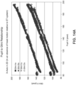
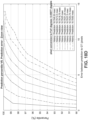
- an uncertainty in the glint position may be 10 to 20 pixels, which can introduce a corresponding error in the gaze direction of about 20 to 50 arcminutes.
- various embodiments of the eye tracking systems described herein obtain images of the eye at different exposure times or at different frame rates.
- longer exposure images of the eye taken at a longer exposure time can show iris or pupil features
- shorter exposure images can show peaks of glints reflected from the cornea.
- the shorter exposure images are sometimes referred to herein as glint images, because they may be used to identify coordinate positions of glints in the images.
- the shorter exposure glint images may, in some implementations, be taken at a high frame rate (HFR) for accurate gaze prediction (e.g., a frame rate that is higher than the frame rate for the longer exposure images).
- HFR high frame rate
- the shorter exposure glint images can be analyzed to provide glint locations to subpixel accuracy leading to accurate predictions of gaze direction (e.g., to within a few arcminutes or better).
- the longer exposure images can be analyzed for pupil center or center of rotation.
- At least a portion of a glint image is temporarily stored in a buffer and that portion of the glint image is analyzed to identify positions of one or more glints that may be located in that portion.
- the portion may comprise a relatively small number of pixels, rows, or columns of the glint image.
- the portion may comprise an n x m portion of the glint image, where n and m are integers that can be in a range from about 1 to 20.
- An additional portion of the glint image may then be stored in the buffer for analysis, until either the entire glint image has been processed or all the glints (commonly, four) have been identified.
- the glint positions e.g., Cartesian coordinates
- the glint image may be deleted from memory (buffer memory or other volatile or non-volatile storage).
- buffering may advantageously permit rapid processing of the glint image to identify glint positions or reduce storage needs of the eye-tracking process since the glint image may be deleted after use.
- the shorter exposure images are not combined with the longer exposure images to obtain a high dynamic range (HDR) image that is used for eye tracking. Rather, in some such embodiments, the shorter exposure images and the longer exposure images are processed separately and are used to determine different information.
- the shorter exposure image may be used for identifying glint positions (e.g., coordinates of the glint centers) or eye gaze direction.
- the shorter exposure image may be deleted from memory (e.g., a buffer) after the glint positions are determined.
- the longer exposure images may be used for determining pupil center or center of rotation, extract iris features for biometric security applications, determine eyelid shape or occlusion of the iris or pupil by the eyelid, measure pupil size, determine render camera parameters, and so forth.
- different processors perform the processing of the shorter and longer exposure images.
- a processor in the head-mounted display may process the shorter exposure images
- a processor in a non-head mounted unit e.g., a beltpack
- a non-head mounted unit e.g., a beltpack
- various embodiments of the multiple exposure time techniques described herein can reap the benefits of HDR luminosity that is collectively provided by both the shorter and longer exposure images, without combining, compositing, merging, or otherwise processing such short and long exposure images together (e.g., as an HDR image).
- various embodiments of the multiple exposure eye tracking system do not use such short and long exposure images to generate or otherwise obtain HDR images.
- the exposure time of the longer exposure image may be in a range from 200 ⁇ s to 1200 ⁇ s, for example, about 700 ⁇ s.
- the longer exposure images can be taken at a frame rate in a range from 10 frames per second (fps) to 60 fps (e.g., 30 fps), 30 fps to 60 fps, or some other range.
- the exposure time of the glint images may be in a range from 5 ⁇ s to 100 ⁇ s, for example, less than about 40 ⁇ s.
- the ratio of the exposure time for the longer exposure image relative to the exposure time for the shorter exposure glint image can be in a range from 5 to 50, 10 to 20, or some other range.
- the glint images can be taken at a frame rate in a range from 50 fps to 1000 fps (e.g., 120 fps), 200 fps to 400 fps, or some other range in various embodiments.
- the ratio of the frame rate for the glint images relative to the frame rate for the longer exposure images can be in a range from 1 to 100, 1 to 50, 2 to 20, 3 to 10, or some other ratio.
- Some wearable systems may utilize foveated rendering techniques in which virtual content may be rendered primarily in the direction the user is looking.
- Embodiments of the eye tracking system can accurately estimate future gaze direction (e.g., out to about 50 ms in the future), which can be used by the rendering system to prepare virtual content for future rendering, and which may advantageously reduce rendering latency and improve user experience.
- a wearable system (also referred to herein as an augmented reality (AR) system) can be configured to present 2D or 3D virtual images to a user.
- the images may be still images, frames of a video, or a video, in combination or the like.
- At least a portion of the wearable system can be implemented on a wearable device that can present a VR, AR, or MR environment, alone or in combination, for user interaction.
- the wearable device can be used interchangeably as an AR device (ARD).
- AR is used interchangeably with the term "MR”.
- FIG. 1 depicts an illustration of a mixed reality scenario with certain virtual reality objects, and certain physical objects viewed by a person.
- an MR scene 100 is depicted wherein a user of an MR technology sees a real-world park-like setting 110 featuring people, trees, buildings in the background, and a concrete platform 120.
- the user of the MR technology also perceives that he "sees" a robot statue 130 standing upon the real-world platform 120, and a cartoon-like avatar character 140 flying by which seems to be a personification of a bumble bee, even though these elements do not exist in the real world.
- each point in the display's visual field may be desirable for each point in the display's visual field to generate an accommodative response corresponding to its virtual depth. If the accommodative response to a display point does not correspond to the virtual depth of that point, as determined by the binocular depth cues of convergence and stereopsis, the human eye may experience an accommodation conflict, resulting in unstable imaging, harmful eye strain, headaches, and, in the absence of accommodation information, almost a complete lack of surface depth.
- VR, AR, and MR experiences can be provided by display systems having displays in which images corresponding to a plurality of depth planes are provided to a viewer.
- the images may be different for each depth plane (e.g., provide slightly different presentations of a scene or object) and may be separately focused by the viewer's eyes, thereby helping to provide the user with depth cues based on the accommodation of the eye required to bring into focus different image features for the scene located on different depth plane or based on observing different image features on different depth planes being out of focus.
- depth cues provide credible perceptions of depth.
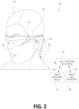
- FIG. 2 illustrates an example of wearable system 200 which can be configured to provide an AR/VR/MR scene.
- the wearable system 200 can also be referred to as the AR system 200.
- the wearable system 200 includes a display 220, and various mechanical and electronic modules and systems to support the functioning of display 220.
- the display 220 may be coupled to a frame 230, which is wearable by a user, wearer, or viewer 210.
- the display 220 can be positioned in front of the eyes of the user 210.
- the display 220 can present AR/VR/MR content to a user.
- the display 220 can comprise a head mounted display (HMD) that is worn on the head of the user.
- HMD head mounted display
- a speaker 240 is coupled to the frame 230 and positioned adjacent the ear canal of the user (in some embodiments, another speaker, not shown, is positioned adjacent the other ear canal of the user to provide for stereo/shapeable sound control).
- the display 220 can include an audio sensor (e.g., a microphone) 232 for detecting an audio stream from the environment and capture ambient sound.
- one or more other audio sensors, not shown, are positioned to provide stereo sound reception. Stereo sound reception can be used to determine the location of a sound source.
- the wearable system 200 can perform voice or speech recognition on the audio stream.
- the wearable system 200 can include an outward-facing imaging system 464 (shown in FIG. 4 ) which observes the world in the environment around the user.
- the wearable system 200 can also include an inward-facing imaging system 462 (shown in FIG. 4 ) which can track the eye movements of the user.
- the inward-facing imaging system may track either one eye's movements or both eyes' movements.
- the inward-facing imaging system 462 may be attached to the frame 230 and may be in electrical communication with the processing modules 260 or 270, which may process image information acquired by the inward-facing imaging system to determine, e.g., the pupil diameters or orientations of the eyes, eye movements or eye pose of the user 210.
- the inward-facing imaging system 462 may include one or more cameras. For example, at least one camera may be used to image each eye. The images acquired by the cameras may be used to determine pupil size or eye pose for each eye separately, thereby allowing presentation of image information to each eye to be dynamically tailored to that eye.
- the wearable system 200 can use the outward-facing imaging system 464 or the inward-facing imaging system 462 to acquire images of a pose of the user.
- the images may be still images, frames of a video, or a video.
- the display 220 can be operatively coupled 250, such as by a wired lead or wireless connectivity, to a local data processing module 260 which may be mounted in a variety of configurations, such as fixedly attached to the frame 230, fixedly attached to a helmet or hat worn by the user, embedded in headphones, or otherwise removably attached to the user 210 (e.g., in a backpack-style configuration, in a belt-coupling style configuration).
- a local data processing module 260 which may be mounted in a variety of configurations, such as fixedly attached to the frame 230, fixedly attached to a helmet or hat worn by the user, embedded in headphones, or otherwise removably attached to the user 210 (e.g., in a backpack-style configuration, in a belt-coupling style configuration).
- the local processing and data module 260 may comprise a hardware processor, as well as digital memory, such as non-volatile memory (e.g., flash memory), both of which may be utilized to assist in the processing, caching, and storage of data.
- the data may include data a) captured from sensors (which may be, e.g., operatively coupled to the frame 230 or otherwise attached to the user 210), such as image capture devices (e.g., cameras in the inward-facing imaging system or the outward-facing imaging system), audio sensors (e.g., microphones), inertial measurement units (IMUs), accelerometers, compasses, global positioning system (GPS) units, radio devices, or gyroscopes; or b) acquired or processed using remote processing module 270 or remote data repository 280, possibly for passage to the display 220 after such processing or retrieval.
- sensors which may be, e.g., operatively coupled to the frame 230 or otherwise attached to the user 210
- image capture devices e.g.
- the local processing and data module 260 may be operatively coupled by communication links 262 or 264, such as via wired or wireless communication links, to the remote processing module 270 or remote data repository 280 such that these remote modules are available as resources to the local processing and data module 260.
- remote processing module 280 and remote data repository 280 may be operatively coupled to each other.
- the remote processing module 270 may comprise one or more processors configured to analyze and process data or image information.
- the remote data repository 280 may comprise a digital data storage facility, which may be available through the internet or other networking configuration in a "cloud" resource configuration. In some embodiments, all data is stored and all computations are performed in the local processing and data module, allowing fully autonomous use from a remote module.
- FIG. 3 schematically illustrates example components of a wearable system.
- FIG. 3 shows a wearable system 200 which can include a display 220 and a frame 230.
- a blown-up view 202 schematically illustrates various components of the wearable system 200.
- one or more of the components illustrated in FIG. 3 can be part of the display 220.
- the various components alone or in combination can collect a variety of data (such as e.g., audio or visual data) associated with the user of the wearable system 200 or the user's environment. It should be appreciated that other embodiments may have additional or fewer components depending on the application for which the wearable system is used. Nevertheless, FIG. 3 provides a basic idea of some of the various components and types of data that may be collected, analyzed, and stored through the wearable system.
- FIG. 3 shows an example wearable system 200 which can include the display 220.
- the display 220 can comprise a display lens 226 that may be mounted to a user's head or a housing or frame 230, which corresponds to the frame 230.
- the display lens 226 may comprise one or more transparent mirrors positioned by the housing 230 in front of the user's eyes 302, 304 and may be configured to bounce projected light 338 into the eyes 302, 304 and facilitate beam shaping, while also allowing for transmission of at least some light from the local environment.
- the wavefront of the projected light beam 338 may be bent or focused to coincide with a desired focal distance of the projected light.
- two wide-field-of-view machine vision cameras 316 can be coupled to the housing 230 to image the environment around the user. These cameras 316 can be dual capture visible light / non-visible (e.g., infrared) light cameras. The cameras 316 may be part of the outward-facing imaging system 464 shown in FIG. 4 . Image acquired by the world cameras 316 can be processed by the pose processor 336. For example, the pose processor 336 can implement one or more object recognizers 708 (e.g., shown in FIG. 7 ) to identify a pose of a user or another person in the user's environment or to identify a physical object in the user's environment.
- object recognizers 708 e.g., shown in FIG. 7
- a pair of scanned-laser shaped-wavefront (e.g., for depth) light projector modules with display mirrors and optics configured to project light 338 into the eyes 302, 304 are shown.
- the depicted view also shows two miniature infrared cameras 324 paired with light sources 326 (such as light emitting diodes "LED"s), which are configured to be able to track the eyes 302, 304 of the user to support rendering and user input.
- the light sources 326 may emit light in the infrared (IR) portion of the optical spectrum, because the eyes 302, 304 are not sensitive to IR light and will not perceive the light sources as shining into the user's eyes, which would be uncomfortable.
- IR infrared
- the cameras 324 may be part of the inward-facing imaging system 462 shown in FIG. 4 .
- the wearable system 200 can further feature a sensor assembly 339, which may comprise X, Y, and Z axis accelerometer capability as well as a magnetic compass and X, Y, and Z axis gyro capability, preferably providing data at a relatively high frequency, such as 200 Hz.
- the sensor assembly 339 may be part of the IMU described with reference to FIG.
- the depicted system 200 can also comprise a head pose processor 336, such as an ASIC (application specific integrated circuit), FPGA (field programmable gate array), or ARM processor (advanced reduced-instruction-set machine), which may be configured to calculate real or near-real time user head pose from wide field of view image information output from the capture devices 316.
- the head pose processor 336 can be a hardware processor and can be implemented as part of the local processing and data module 260 shown in FIG. 2 .
- the wearable system can also include one or more depth sensors 234.
- the depth sensor 234 can be configured to measure the distance between an object in an environment to a wearable device.
- the depth sensor 234 may include a laser scanner (e.g., a lidar), an ultrasonic depth sensor, or a depth sensing camera.
- the cameras 316 may also be considered as depth sensors 234.
- a processor 332 configured to execute digital or analog processing to derive pose from the gyro, compass, or accelerometer data from the sensor assembly 339.
- the processor 332 may be part of the local processing and data module 260 shown in FIG. 2 .
- the wearable system 200 as shown in FIG. 3 can also include a position system such as, e.g., a GPS 337 (global positioning system) to assist with pose and positioning analyses.
- the GPS may further provide remotely-based (e.g., cloud-based) information about the user's environment. This information may be used for recognizing objects or information in user's environment.
- the wearable system may combine data acquired by the GPS 337 and a remote computing system (such as, e.g., the remote processing module 270, another user's ARD, etc.) which can provide more information about the user's environment.
- a remote computing system such as, e.g., the remote processing module 270, another user's ARD, etc.
- the wearable system can determine the user's location based on GPS data and retrieve a world map (e.g., by communicating with a remote processing module 270) including virtual objects associated with the user's location.
- the wearable system 200 can monitor the environment using the world cameras 316 (which may be part of the outward-facing imaging system 464 shown in FIG. 4 ). Based on the images acquired by the world cameras 316, the wearable system 200 can detect objects in the environment. The wearable system can further use data acquired by the GPS 337 to interpret the characters.
- the wearable system 200 may also comprise a rendering engine 334 which can be configured to provide rendering information that is local to the user to facilitate operation of the scanners and imaging into the eyes of the user, for the user's view of the world.
- the rendering engine 334 may be implemented by a hardware processor (such as, e.g., a central processing unit or a graphics processing unit). In some embodiments, the rendering engine is part of the local processing and data module 260.
- the rendering engine 334 may comprise the light-field render controller 618 described with reference to FIGS. 6 and 7 .
- the rendering engine 334 can be communicatively coupled (e.g., via wired or wireless links) to other components of the wearable system 200.
- the rendering engine 334 can be coupled to the eye cameras 324 via communication link 274, and be coupled to a projecting subsystem 318 (which can project light into user's eyes 302, 304 via a scanned laser arrangement in a manner similar to a retinal scanning display) via the communication link 272.
- the rendering engine 334 can also be in communication with other processing units such as, e.g., the sensor pose processor 332 and the image pose processor 336 via links 276 and 294 respectively.
- the cameras 324 may be utilized to track the eye pose to support rendering and user input. Some example eye poses may include where the user is looking or at what depth he or she is focusing (which may be estimated with eye vergence).
- the cameras 324 and the infrared light sources 326 can be used to provide data to for the multiple exposure time eye-tracking techniques described herein.
- the GPS 337, gyros, compass, and accelerometers 339 may be utilized to provide coarse or fast pose estimates.
- One or more of the cameras 316 can acquire images and pose, which in conjunction with data from an associated cloud computing resource, may be utilized to map the local environment and share user views with others.
- the example components depicted in FIG. 3 are for illustration purposes only. Multiple sensors and other functional modules are shown together for ease of illustration and description. Some embodiments may include only one or a subset of these sensors or modules. Further, the locations of these components are not limited to the positions depicted in FIG. 3 . Some components may be mounted to or housed within other components, such as a belt-mounted component, a hand-held component, or a helmet component. As one example, the image pose processor 336, sensor pose processor 332, and rendering engine 334 may be positioned in a beltpack and configured to communicate with other components of the wearable system via wireless communication, such as ultra-wideband, Wi-Fi, Bluetooth, etc., or via wired communication.
- wireless communication such as ultra-wideband, Wi-Fi, Bluetooth, etc.
- the cameras 324 may be utilized to measure where the centers of a user's eyes are geometrically verged to, which, in general, coincides with a position of focus, or "depth of focus", of the eyes.
- a 3-dimensional surface of all points the eyes verge to can be referred to as the "horopter".
- the focal distance may take on a finite number of depths, or may be infinitely varying.
- Light projected from the vergence distance appears to be focused to the subject eye 302, 304, while light in front of or behind the vergence distance is blurred. Examples of wearable devices and other display systems of the present disclosure are also described in U.S. Patent Publication No. 2016/0270656 .
- the human visual system is complicated and providing a realistic perception of depth is challenging. Viewers of an object may perceive the object as being three-dimensional due to a combination of vergence and accommodation. Vergence movements (e.g., rolling movements of the pupils toward or away from each other to converge the lines of sight of the eyes to fixate upon an object) of the two eyes relative to each other are closely associated with focusing (or "accommodation") of the lenses of the eyes.
- Vergence movements e.g., rolling movements of the pupils toward or away from each other to converge the lines of sight of the eyes to fixate upon an object
- the eye vergence may be tracked with the cameras 324, and the rendering engine 334 and projection subsystem 318 may be utilized to render all objects on or close to the horopter in focus, and all other objects at varying degrees of defocus (e.g., using intentionally-created blurring).
- the system 220 renders to the user at a frame rate of about 60 frames per second or greater.
- the cameras 324 may be utilized for eye tracking, and software may be configured to pick up not only vergence geometry but also focus location cues to serve as user inputs.
- such a display system is configured with brightness and contrast suitable for day or night use.
- the wearable system 200 is configured to display one or more virtual images based on the accommodation of the user's eyes. Unlike prior 3D display approaches that force the user to focus where the images are being projected, in some embodiments, the wearable system is configured to automatically vary the focus of projected virtual content to allow for a more comfortable viewing of one or more images presented to the user. For example, if the user's eyes have a current focus of 1 m, the image may be projected to coincide with the user's focus. If the user shifts focus to 3 m, the image is projected to coincide with the new focus. Thus, rather than forcing the user to a predetermined focus, the wearable system 200 of some embodiments allows the user's eye to a function in a more natural manner.
- Such a wearable system 200 may eliminate or reduce the incidences of eye strain, headaches, and other physiological symptoms typically observed with respect to virtual reality devices.
- various embodiments of the wearable system 200 are configured to project virtual images at varying focal distances, through one or more variable focus elements (VFEs).
- VFEs variable focus elements
- 3D perception may be achieved through a multi-plane focus system that projects images at fixed focal planes away from the user.
- Other embodiments employ variable plane focus, wherein the focal plane is moved back and forth in the z-direction to coincide with the user's present state of focus.
- wearable system 200 may employ eye tracking to determine a vergence of the user's eyes, determine the user's current focus, and project the virtual image at the determined focus.
- wearable system 200 comprises a light modulator that variably projects, through a fiber scanner, or other light generating source, light beams of varying focus in a raster pattern across the retina.
- a spatial light modulator may project the images to the user through various optical components. For example, as described further below, the spatial light modulator may project the images onto one or more waveguides, which then transmit the images to the user.
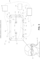
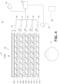
- FIG. 4 illustrates an example of a waveguide stack for outputting image information to a user.
- a wearable system 400 includes a stack of waveguides, or stacked waveguide assembly 480 that may be utilized to provide three-dimensional perception to the eye/brain using a plurality of waveguides 432b, 434b, 436b, 438b, 440b.
- the wearable system 400 may correspond to wearable system 200 of FIG. 2 , with FIG. 4 schematically showing some parts of that wearable system 200 in greater detail.
- the waveguide assembly 480 may be integrated into the display 220 of FIG. 2 .
- the waveguide assembly 480 may also include a plurality of features 458, 456, 454, 452 between the waveguides.
- the features 458, 456, 454, 452 may be lenses.
- the features 458, 456, 454, 452 may not be lenses. Rather, they may simply be spacers (e.g., cladding layers or structures for forming air gaps).
- the waveguides 432b, 434b, 436b, 438b, 440b or the plurality of lenses 458, 456, 454, 452 may be configured to send image information to the eye with various levels of wavefront curvature or light ray divergence.
- Each waveguide level may be associated with a particular depth plane and may be configured to output image information corresponding to that depth plane.
- Image injection devices 420, 422, 424, 426, 428 may be utilized to inject image information into the waveguides 440b, 438b, 436b, 434b, 432b, each of which may be configured to distribute incoming light across each respective waveguide, for output toward the eye 410.
- a single beam of light may be injected into each waveguide to output an entire field of cloned collimated beams that are directed toward the eye 410 at particular angles (and amounts of divergence) corresponding to the depth plane associated with a particular waveguide.
- the image injection devices 420, 422, 424, 426, 428 are discrete displays that each produce image information for injection into a corresponding waveguide 440b, 438b, 436b, 434b, 432b, respectively.
- the image injection devices 420, 422, 424, 426, 428 are the output ends of a single multiplexed display which may, e.g., pipe image information via one or more optical conduits (such as fiber optic cables) to each of the image injection devices 420, 422, 424, 426, 428.
- a controller 460 controls the operation of the stacked waveguide assembly 480 and the image injection devices 420, 422, 424, 426, 428.
- the controller 460 includes programming (e.g., instructions in a non-transitory computer-readable medium) that regulates the timing and provision of image information to the waveguides 440b, 438b, 436b, 434b, 432b.
- the controller 460 may be a single integral device, or a distributed system connected by wired or wireless communication channels.
- the controller 460 may be part of the processing modules 260 or 270 (illustrated in FIG. 2 ) in some embodiments.
- the waveguides 440b, 438b, 436b, 434b, 432b may be configured to propagate light within each respective waveguide by total internal reflection (TIR).
- TIR total internal reflection
- the waveguides 440b, 438b, 436b, 434b, 432b may each be planar or have another shape (e.g., curved), with major top and bottom surfaces and edges extending between those major top and bottom surfaces.
- the waveguides 440b, 438b, 436b, 434b, 432b may each include light extracting optical elements 440a, 438a, 436a, 434a, 432a that are configured to extract light out of a waveguide by redirecting the light, propagating within each respective waveguide, out of the waveguide to output image information to the eye 410.
- Extracted light may also be referred to as outcoupled light
- light extracting optical elements may also be referred to as outcoupling optical elements.
- An extracted beam of light is outputted by the waveguide at locations at which the light propagating in the waveguide strikes a light redirecting element.
- the light extracting optical elements may, for example, be reflective or diffractive optical features. While illustrated disposed at the bottom major surfaces of the waveguides 440b, 438b, 436b, 434b, 432b for ease of description and drawing clarity, in some embodiments, the light extracting optical elements 440a, 438a, 436a, 434a, 432a may be disposed at the top or bottom major surfaces, or may be disposed directly in the volume of the waveguides 440b, 438b, 436b, 434b, 432b.
- the light extracting optical elements 440a, 438a, 436a, 434a, 432a may be formed in a layer of material that is attached to a transparent substrate to form the waveguides 440b, 438b, 436b, 434b, 432b.
- the waveguides 440b, 438b, 436b, 434b, 432b may be a monolithic piece of material and the light extracting optical elements 440a, 438a, 436a, 434a, 432a may be formed on a surface or in the interior of that piece of material.
- each waveguide 440b, 438b, 436b, 434b, 432b is configured to output light to form an image corresponding to a particular depth plane.
- the waveguide 432b nearest the eye may be configured to deliver collimated light, as injected into such waveguide 432b, to the eye 410.
- the collimated light may be representative of the optical infinity focal plane.
- the next waveguide up 434b may be configured to send out collimated light which passes through the first lens 452 (e.g., a negative lens) before it can reach the eye 410.
- First lens 452 may be configured to create a slight convex wavefront curvature so that the eye/brain interprets light coming from that next waveguide up 434b as coming from a first focal plane closer inward toward the eye 410 from optical infinity.
- the third up waveguide 436b passes its output light through both the first lens 452 and second lens 454 before reaching the eye 410.
- the combined optical power of the first and second lenses 452 and 454 may be configured to create another incremental amount of wavefront curvature so that the eye/brain interprets light coming from the third waveguide 436b as coming from a second focal plane that is even closer inward toward the person from optical infinity than was light from the next waveguide up 434b.
- the other waveguide layers e.g., waveguides 438b, 440b
- lenses e.g., lenses 456, 458
- the highest waveguide 440b in the stack sending its output through all of the lenses between it and the eye for an aggregate focal power representative of the closest focal plane to the person.
- a compensating lens layer 430 may be disposed at the top of the stack to compensate for the aggregate power of the lens stack 458, 456, 454, 452 below.
- Compensating lens layer 430 and the stacked waveguide assembly 480 as a whole may be configured such that light coming from the world 470 is conveyed to the eye 410 at substantially the same level of divergence (or collimation) as the light had when it was initially received by the stacked waveguide assembly 480.) Such a configuration provides as many perceived focal planes as there are available waveguide/lens pairings. Both the light extracting optical elements of the waveguides and the focusing aspects of the lenses may be static (e.g., not dynamic or electro-active). In some alternative embodiments, either or both may be dynamic using electro-active features.
- the light extracting optical elements 440a, 438a, 436a, 434a, 432a may be configured to both redirect light out of their respective waveguides and to output this light with the appropriate amount of divergence or collimation for a particular depth plane associated with the waveguide.
- waveguides having different associated depth planes may have different configurations of light extracting optical elements, which output light with a different amount of divergence depending on the associated depth plane.
- the light extracting optical elements 440a, 438a, 436a, 434a, 432a may be volumetric or surface features, which may be configured to output light at specific angles.
- the light extracting optical elements 440a, 438a, 436a, 434a, 432a may be volume holograms, surface holograms, and/or diffraction gratings.
- Light extracting optical elements, such as diffraction gratings, are described in U.S. Patent Publication No. 2015/0178939, published June 25, 2015 .
- the light extracting optical elements 440a, 438a, 436a, 434a, 432a are diffractive features that form a diffraction pattern, or "diffractive optical element” (also referred to herein as a "DOE").
- the DOE has a relatively low diffraction efficiency so that only a portion of the light of the beam is deflected away toward the eye 410 with each intersection of the DOE, while the rest continues to move through a waveguide via total internal reflection.
- the light carrying the image information can thus be divided into a number of related exit beams that exit the waveguide at a multiplicity of locations and the result is a fairly uniform pattern of exit emission toward the eye 304 for this particular collimated beam bouncing around within a waveguide.
- one or more DOEs may be switchable between "on” state in which they actively diffract, and "off” state in which they do not significantly diffract.
- a switchable DOE may comprise a layer of polymer dispersed liquid crystal, in which microdroplets comprise a diffraction pattern in a host medium, and the refractive index of the microdroplets can be switched to substantially match the refractive index of the host material (in which case the pattern does not appreciably diffract incident light) or the microdroplet can be switched to an index that does not match that of the host medium (in which case the pattern actively diffracts incident light).
- the number and distribution of depth planes or depth of field may be varied dynamically based on the pupil sizes or orientations of the eyes of the viewer.
- Depth of field may change inversely with a viewer's pupil size.
- the depth of field increases such that one plane that is not discernible because the location of that plane is beyond the depth of focus of the eye may become discernible and appear more in focus with reduction of pupil size and commensurate with the increase in depth of field.
- the number of spaced apart depth planes used to present different images to the viewer may be decreased with the decreased pupil size.
- a viewer may not be able to clearly perceive the details of both a first depth plane and a second depth plane at one pupil size without adjusting the accommodation of the eye away from one depth plane and to the other depth plane.
- These two depth planes may, however, be sufficiently in focus at the same time to the user at another pupil size without changing accommodation.
- the display system may vary the number of waveguides receiving image information based upon determinations of pupil size or orientation, or upon receiving electrical signals indicative of particular pupil size or orientation. For example, if the user's eyes are unable to distinguish between two depth planes associated with two waveguides, then the controller 460 (which may be an embodiment of the local processing and data module 260) can be configured or programmed to cease providing image information to one of these waveguides.
- the controller 460 which may be an embodiment of the local processing and data module 260
- the DOEs for a waveguide are switchable between the on and off states, the DOEs may be switched to the off state when the waveguide does receive image information.
- the FOR may include 4 ⁇ steradians of solid angle surrounding the wearable system 400 because the wearer can move his body, head, or eyes to perceive substantially any direction in space. In other contexts, the wearer's movements may be more constricted, and accordingly the wearer's FOR may subtend a smaller solid angle. Images obtained from the outward-facing imaging system 464 can be used to track gestures made by the user (e.g., hand or finger gestures), detect objects in the world 470 in front of the user, and so forth.
- gestures made by the user e.g., hand or finger gestures
- the wearable system 400 can include an audio sensor 232, e.g., a microphone, to capture ambient sound. As described above, in some embodiments, one or more other audio sensors can be positioned to provide stereo sound reception useful to the determination of location of a speech source.
- the audio sensor 232 can comprise a directional microphone, as another example, which can also provide such useful directional information as to where the audio source is located.
- the wearable system 400 can use information from both the outward-facing imaging system 464 and the audio sensor 230 in locating a source of speech, or to determine an active speaker at a particular moment in time, etc.
- the wearable system 400 can use the voice recognition alone or in combination with a reflected image of the speaker (e.g., as seen in a mirror) to determine the identity of the speaker.
- the wearable system 400 can determine a position of the speaker in an environment based on sound acquired from directional microphones. The wearable system 400 can parse the sound coming from the speaker's position with speech recognition algorithms to determine the content of the speech and use voice recognition techniques to determine the identity (e.g., name or other demographic information) of the speaker.
- the wearable system 400 can also include an inward-facing imaging system 466 (comprising, e.g., a digital camera), which observes the movements of the user, such as the eye movements (e.g., for eye-tracking) and the facial movements.
- the inward-facing imaging system 466 may be used to capture images of the eye 410 to determine the size and/or orientation of the pupil of the eye 304.
- the inward-facing imaging system 466 can be used to obtain images for use in determining the direction the user is looking (e.g., eye pose) or for biometric identification of the user (e.g., via iris identification).
- the inward-facing imaging system 426 can be used to provide input images and information for the multiple exposure time eye-tracking techniques described herein.
- At least one camera may be utilized for each eye, to separately determine the pupil size or eye pose of each eye independently, thereby allowing the presentation of image information to each eye to be dynamically tailored to that eye.
- the pupil diameter or orientation of only a single eye 410 e.g., using only a single camera per pair of eyes
- the images obtained by the inward-facing imaging system 466 may be analyzed to determine the user's eye pose or mood, which can be used by the wearable system 400 to decide which audio or visual content should be presented to the user.
- the wearable system 400 may also determine head pose (e.g., head position or head orientation) using sensors such as IMUs, accelerometers, gyroscopes, etc.
- the inward-facing imaging system 426 can comprise the cameras 324 and light sources 326 (e.g., IR LEDs) described with reference to FIG. 3 .
- the wearable system 400 can include a user input device 466 by which the user can input commands to the controller 460 to interact with the wearable system 400.
- the user input device 466 can include a trackpad, a touchscreen, a joystick, a multiple degree-of-freedom (DOF) controller, a capacitive sensing device, a game controller, a keyboard, a mouse, a directional pad (D-pad), a wand, a haptic device, a totem (e.g., functioning as a virtual user input device), and so forth.
- DOF multiple degree-of-freedom
- a multi-DOF controller can sense user input in some or all possible translations (e.g., left/right, forward/backward, or up/down) or rotations (e.g., yaw, pitch, or roll) of the controller.
- a multi-DOF controller which supports the translation movements may be referred to as a 3DOF while a multi-DOF controller which supports the translations and rotations may be referred to as 6DOF.
- the user may use a finger (e.g., a thumb) to press or swipe on a touch-sensitive input device to provide input to the wearable system 400 (e.g., to provide user input to a user interface provided by the wearable system 400).
- the user input device 466 may be held by the user's hand during the use of the wearable system 400.
- the user input device 466 can be in wired or wireless communication with the wearable system 400.
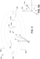
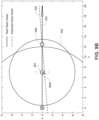
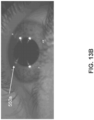
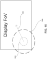
- FIG. 5 illustrates an image of an eye 500 with eyelids 504, sclera 508 (the "white” of the eye), iris 512, and pupil 516.
- Curve 516a shows the pupillary boundary between the pupil 516 and the iris 512
- curve 512a shows the limbic boundary between the iris 512 and the sclera 508.
- the eyelids 504 include an upper eyelid 504a and a lower eyelid 504b.
- the eye 500 is illustrated in a natural resting pose (e.g., in which the user's face and gaze are both oriented as they would be toward a distant object directly ahead of the user).
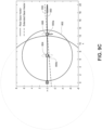
- the natural resting pose of the eye 500 can be indicated by a natural resting direction 520, which is a direction orthogonal to the surface of the eye 500 when in the natural resting pose (e.g., directly out of the plane for the eye 500 shown in FIG. 5 ) and in this example, centered within the pupil 516.
- a natural resting direction 520 is a direction orthogonal to the surface of the eye 500 when in the natural resting pose (e.g., directly out of the plane for the eye 500 shown in FIG. 5 ) and in this example, centered within the pupil 516.
- the current eye pose can be determined with reference to an eye pose direction 524, which is a direction orthogonal to the surface of the eye (and centered in within the pupil 516) but oriented toward the object at which the eye is currently directed.
- the pose of the eye 500 can be expressed as two angular parameters indicating an azimuthal deflection and a zenithal deflection of the eye pose direction 524 of the eye, both relative to the natural resting direction 520 of the eye.
- these angular parameters can be represented as ⁇ (azimuthal deflection, determined from a fiducial azimuth) and ⁇ (zenithal deflection, sometimes also referred to as a polar deflection).
- angular roll of the eye around the eye pose direction 524 can be included in the determination of eye pose, and angular roll can be included in the eye-tracking.
- other techniques for determining the eye pose can be used, for example, a pitch, yaw, and optionally roll system.
- the eye pose can be provided as a 2DOF or a 3DOF orientation.
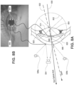
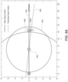
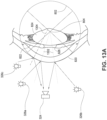
- the light sources 326 can illuminate the eye 500 (e.g., in the IR), and reflections of the light sources from the eye (typically off of the cornea) are referred to as glints.
- FIG. 5 schematically shows an example where there are four glints 550. The positions, number, brightnesses, etc. of the glints 550 can depend on the position and number of the light sources 326, the pose of the eye, and so forth.
- an eye-tracking camera 324 can obtain eye images, and a processor can analyze the eye images to determine positions and movements of the glints for eye-tracking. In some embodiments, multiple eye images with different exposure times or different frame rates can be used to provide high accuracy eye tracking.
- An eye image can be obtained from a video using any appropriate process, for example, using a video processing algorithm that can extract an image from one or more sequential frames (or non-sequential frames).
- the inward-facing imaging system 426 of FIG. 4 or the camera 324 and light source 326 of FIG. 3 can be utilized to provide the video or image(s) of one or both of the eyes.
- the pose of the eye can be determined from the eye image using a variety of eye-tracking techniques, for example, the multiple exposure time techniques for accurate corneal glint detection that are described herein.
- an eye pose can be determined by considering the lensing effects of the cornea on light sources that are provided. Any suitable eye tracking technique can be used for determining eye pose in the eyelid shape estimation techniques described herein.
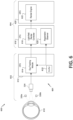
- FIG. 6 illustrates a schematic diagram of a wearable system 600 that includes an eye tracking system 601.
- the wearable system 600 may be an embodiment of the wearable systems 200 and 400 described with reference to FIGS. 2 to 4 .
- the wearable system 600 may, in at least some embodiments, include components located in a head-mounted unit 602 and components located in a non-head-mounted unit 604.
- Non-head mounted unit 604 may be, as examples, a belt-mounted component, a hand-held component, a component in a backpack, a remote component, etc. Incorporating some of the components of the wearable system 600 in non-head-mounted unit 604 may help to reduce the size, weight, complexity, and cost of the head-mounted unit 602.
- some or all of the functionality described as being performed by one or more components of head-mounted unit 602 and/or non-head mounted unit 604 may be provided by way of one or more components included elsewhere in the wearable system 600.
- some or all of the functionality described below in association with a CPU 612 of head-mounted unit 602 may be provided by way of a CPU 616 of non-head mounted unit 604, and vice versa.
- some or all of such functionality may be provided by way of peripheral devices of wearable system 600.
- some or all of such functionality may be provided by way of one or more cloud computing devices or other remotely-located computing devices in a manner similar to that which has been described above with reference to FIG. 2 .
- wearable system 600 can include an eye tracking system 601 including a camera 324 that captures images of a user's eye 610.
- the eye tracking system may also include light sources 326a and 326b (such as light emitting diodes "LED"s).
- the light sources 326a and 326b may generate glints (e.g., reflections off of the user's eyes that appear in images of the eye captured by camera 324). Schematic examples of glints 550 are shown in FIG. 5 .
- the positions of the light sources 326a and 326b relative to the camera 324 may be known and, as a consequence, the positions of the glints within images captured by camera 324 can be used in tracking the user's eyes (as will be described in more detail below).
- Eye tracking module 614 may receive images from eye tracking camera(s) 324 and may analyze the images to extract various pieces of information. As described herein, the images from the eye tracking camera(s) may include shorter exposure (glint) images and longer exposure images. As examples, the eye tracking module 614 may detect the user's eye poses, a three-dimensional position of the user's eye relative to the eye tracking camera 324 (and to the head-mounted unit 602), the direction one or both of the user's eyes 610 are focused on, the user's vergence depth (e.g., the depth from the user at which the user is focusing on), the positions of the user's pupils, the positions of the user's cornea and corneal sphere, the center of rotation of each of the user's eyes, or the center of perspective of each of the user's eyes. As shown in FIG. 6 , the eye tracking module 614 may be a software module implemented using a CPU 612 in a head-mounted unit 602.
- Data from eye tracking module 614 may be provided to other components in the wearable system. As example, such data may be transmitted to components in a non-head-mounted unit 604 such as CPU 616 including software modules for a light-field render controller 618 and a registration observer 620.
- a non-head-mounted unit 604 such as CPU 616 including software modules for a light-field render controller 618 and a registration observer 620.
- the functionality may be performed differently than shown in FIG. 6 (or FIG. 7 ), which are intended to be illustrative and not limiting.
- the shorter exposure glint images can be processed by the CPU 612 in the head-mounted unit 602 (which may be disposed in the camera 324) and the longer exposure images can be processed by the CPU 616 (or GPU 621) in the non-head mounted unit 604 (e.g., in a beltpack).
- some of the eye tracking functionality performed by the eye tracking module 614 may be performed by a processor (e.g., the CPU 616 or GPU 621) in the non-head mounted unit 604 (e.g., the beltpack). This may be advantageous because some of the eye tracking functionality may be CPU-intensive and may, in some cases, be performed more efficiently or rapidly by a more powerful processor disposed in the non-head mounted unit 604.
- a processor e.g., the CPU 616 or GPU 621
- the non-head mounted unit 604 e.g., the beltpack
- Render controller 618 may use information from eye tracking module 614 to adjust images displayed to the user by render engine 622 (e.g., a render engine that may be a software module in GPU 620 and that may provide images to the display 220). As an example, the render controller 618 may adjust images displayed to the user based on the user's center of rotation or center of perspective. In particular, the render controller 618 may use information on the user's center of perspective to simulate a render camera (e.g., to simulate collecting images from the user's perspective) and may adjust images displayed to the user based on the simulated render camera. Further details discussing the creation, adjustment, and use of render cameras in rendering processes are provided in U.S. Patent Application No. 15/274,823 , published as U.S. Patent Application Publication No. 2017/0091996 , entitled "METHODS AND SYSTEMS FOR DETECTING AND COMBINING STRUCTURAL FEATURES IN 3D RECONSTRUCTION,".
- one or more modules (or components) of the system 600 may determine the position and orientation of the render camera within render space based on the position and orientation of the user's head and eyes (e.g., as determined based on head pose and eye tracking data, respectively).
- the system 600 may effectively map the position and orientation of the user's head and eyes to particular locations and angular positions within a 3D virtual environment, place and orient render cameras at the particular locations and angular positions within the 3D virtual environment, and render virtual content for the user as it would be captured by the render camera. Further details discussing real world to virtual world mapping processes are provided in U.S. Patent Application No.
- the render controller 618 may adjust the depths at which images are displayed by selecting which depth plane (or depth planes) are utilized at any given time to display the images.
- a depth plane switch may be carried out through an adjustment of one or more intrinsic render camera parameters.
- Registration observer 620 may use information from the eye tracking module 614 to identify whether the head-mounted unit 602 is properly positioned on a user's head.
- the eye tracking module 614 may provide eye location information, such as the positions of the centers of rotation of the user's eyes, indicative of the three-dimensional position of the user's eyes relative to camera 324 and head-mounted unit 602 and the eye tracking module 614 may use the location information to determine if display 220 is properly aligned in the user's field of view, or if the head-mounted unit 602 (or headset) has slipped or is otherwise misaligned with the user's eyes.
- the registration observer 620 may be able to determine if the head-mounted unit 602 has slipped down the user's nose bridge, thus moving display 220 away and down from the user's eyes (which may be undesirable), if the head-mounted unit 602 has been moved up the user's nose bridge, thus moving display 220 closer and up from the user's eyes, if the head-mounted unit 602 has been shifted left or right relative the user's nose bridge, if the head-mounted unit 602 has been lifted above the user's nose bridge, or if the head-mounted unit 602 has been moved in these or other ways away from a desired position or range of positions.
- registration observer 620 may be able to determine if head-mounted unit 602, in general, and displays 220, in particular, are properly positioned in front of the user's eyes. In other words, the registration observer 620 may determine if a left display in display system 220 is appropriately aligned with the user's left eye and a right display in display system 220 is appropriately aligned with the user's right eye. The registration observer 620 may determine if the head-mounted unit 602 is properly positioned by determining if the head-mounted unit 602 is positioned and oriented within a desired range of positions and/or orientations relative to the user's eyes. Example registration observation and feedback techniques, which may be utilized by the registration observer 620, are described in U.S.
- the wearable system may include a plurality of discrete depth planes formed by a plurality of waveguides, each conveying image information with a varying level of wavefront curvature.
- a wearable system may include one or more variable depth planes, such as an optical element that conveys image information with a level of wavefront curvature that varies over time.
- the render engine 622 can convey content to a user at a selected depth (e.g., cause the render engine 622 to direct the display 220 to switch depth planes), based in part of the user's vergence depth.
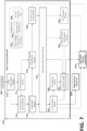
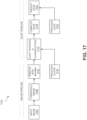
- FIG. 7 A block diagram of an example eye tracking module 614 is shown in FIG. 7 .
- the eye tracking module 614 may include a variety of different submodules, may provide a variety of different outputs, and may utilize a variety of available data in tracking the user's eyes.
- eye tracking module 614 may utilize available data including eye tracking extrinsics and intrinsics, such as the geometric arrangements of the eye tracking camera 324 relative to the light sources 326 and the head-mounted-unit 602; assumed eye dimensions 704 such as a typical distance of approximately 4.7 mm between a user's center of cornea curvature and the average center of rotation of the user's eye or typical distances between a user's center of rotation and center of perspective; and per-user calibration data 706 such as a particular user's interpupillary distance. Additional examples of extrinsics, intrinsics, and other information that may be employed by the eye tracking module 614 are described in U.S. Patent Application No. 15/497,726, filed April 26, 2017 , published as U.S.
- Patent Application Publication No. 2018/0018515 entitled “IRIS BOUNDARY ESTIMATION USING CORNEA CURVATURE,”.
- Example eye tracking modules and techniques which may be implemented as the eye tracking module 614 or otherwise utilized by the eye tracking module 614, are described in U.S. Patent Application No. 16/250,931, filed January 17, 2019 , published as U.S. Patent Application Publication No. 2019/0243448 , entitled “EYE CENTER OF ROTATION DETERMINATION, DEPTH PLANE SELECTION, AND RENDER CAMERA POSITIONING IN DISPLAY SYSTEMS,”.
- Pupil identification module 712 may receive preprocessed images from the image preprocessing module 710 and may identify regions of those images that include the user's pupil.
- the pupil identification module 712 may, in some embodiments, determine the coordinates of the position, or coordinates, of the center, or centroid, of the user's pupil in the eye tracking images from camera 324.
- the pupil identification module 712 may output pupil identification data, which may indicate which regions of the preprocessing images module 712 identified as showing the user's pupil, to glint detection and labeling module 714.
- the pupil identification module 712 may provide the 2D coordinates of the user's pupil (e.g., the 2D coordinates of the centroid of the user's pupil) within each eye tracking image to glint detection module 714.
- pupil identification module 712 may also provide pupil identification data of the same sort to coordinate system normalization module 718.
- Pupil detection techniques which may be utilized by pupil identification module 712, are described in U.S. Patent Publication No. 2017/0053165, published February 23, 2017 and in U.S. Patent Publication No. 2017/0053166, published February 23, 2017 .
- Glint detection and labeling module 714 may receive preprocessed images from module 710 and pupil identification data from module 712. Glint detection module 714 may use this data to detect and/or identify glints (e.g., reflections off of the user's eye of the light from light sources 326) within regions of the preprocessed images that show the user's pupil. As an example, the glint detection module 714 may search for bright regions within the eye tracking image, sometimes referred to herein as "blobs" or local intensity maxima that are in the vicinity of the user's pupil or iris.
- glint detection module 714 may search for bright regions within the eye tracking image, sometimes referred to herein as "blobs" or local intensity maxima that are in the vicinity of the user's pupil or iris.
- the glint detection module 714 may rescale (e.g., enlarge) the pupil ellipse to encompass additional glints.
- the glint detection module 714 may filter glints by size or by intensity.
- the glint detection module 714 may also determine the 2D positions of each of the glints within the eye tracking image. In at least some examples, the glint detection module 714 may determine the 2D positions of the glints relative to the user's pupil, which may also be referred to as the pupil-glint vectors.
- Glint detection and labeling module 714 may label the glints and output the preprocessing images with labeled glints to the 3D cornea center estimation module 716. Glint detection and labeling module 714 may also pass along data such as preprocessed images from module 710 and pupil identification data from module 712. In some implementations, the glint detection and labeling module 714 may determine which light source (e.g., from among a plurality of light sources of the system including infrared light sources 326a and 326b) produced each identified glint. In these examples, the glint detection and labeling module 714 may label the glints with information identifying the associated light source and output the preprocessing images with labeled glints to the 3D cornea center estimation module 716.
- the glint detection and labeling module 714 may label the glints with information identifying the associated light source and output the preprocessing images with labeled glints to the 3D cornea
- Pupil and glint detection can use any suitable techniques.
- edge detection can be applied to the eye image to identify glints, pupils, or irises.
- Edge detection can be applied by various edge detectors, edge detection algorithms, or filters.
- a Canny Edge detector can be applied to the image to detect edges such as in lines of the image. Edges may include points located along a line that correspond to the local maximum derivative.
- the pupillary boundary 516a or the iris (limbic) boundary 512a can be located using a Canny edge detector. With the location of the pupil or iris determined, various image processing techniques can be used to detect the "pose" of the pupil 116.
- the pose can also be referred to as the gaze, pointing direction, or the orientation of the eye.
- the pupil may be looking leftwards towards an object, and the pose of the pupil could be classified as a leftwards pose.
- Other methods can be used to detect the location of the pupil or glints.
- a concentric ring can be located in an eye image using a Canny Edge detector.
- an integro-differential operator can be used to find the pupillary or limbus boundaries of the iris.
- the Daugman integro-differential operator, the Hough transform, or other iris segmentation techniques can be used to return a curve that estimates the boundary of the pupil or the iris.
- the modules 712, 714 can apply the glint detection techniques described herein, which may use multiple eye images captured with different exposure times or different frame rates.
- 3D cornea center estimation module 716 may receive preprocessed images including detected glint data and pupil (or iris) identification data from modules 710, 712, 714. 3D cornea center estimation module 716 may use these data to estimate the 3D position of the user's cornea. In some embodiments, the 3D cornea center estimation module 716 may estimate the 3D position of an eye's center of cornea curvature or a user's corneal sphere, e.g., the center of an imaginary sphere having a surface portion generally coextensive with the user's cornea.
- the 3D cornea center estimation module 716 may provide data indicating the estimated 3D coordinates of the corneal sphere and/or user's cornea to the coordinate system normalization module 718, the optical axis determination module 722, and/or the light-field render controller 618.
- Techniques for estimating the positions of eye features such as a cornea or corneal sphere, which may be utilized by 3D cornea center estimation module 716 and other modules in the wearable systems of the present disclosure are discussed in U.S. Patent Application No. 15/497,726, filed April 26, 2017 , published as U.S. Patent Application Publication No. 2018/0018515 , which is incorporated by reference herein in its entirety.
- Coordinate system normalization module 718 may optionally (as indicated by its dashed outline) be included in eye tracking module 614. Coordinate system normalization module 718 may receive data indicating the estimated 3D coordinates of the center of the user's cornea (and/or the center of the user's corneal sphere) from the 3D cornea center estimation module 716 and may also receive data from other modules. Coordinate system normalization module 718 may normalize the eye camera coordinate system, which may help to compensate for slippages of the wearable device (e.g., slippages of the head-mounted component from its normal resting position on the user's head, which may be identified by registration observer 620).
- the wearable device e.g., slippages of the head-mounted component from its normal resting position on the user's head, which may be identified by registration observer 620.
- Coordinate system normalization module 718 may rotate the coordinate system to align the z-axis (e.g., the vergence depth axis) of the coordinate system with the cornea center (e.g., as indicated by the 3D cornea center estimation module 716) and may translate the camera center (e.g., the origin of the coordinate system) to a predetermined distance away from the cornea center such as 30 mm (e.g., module 718 may enlarge or shrink the eye tracking image depending on whether the eye camera 324 was determined to be nearer or further than the predetermined distance). With this normalization process, the eye tracking module 614 may be able to establish a consistent orientation and distance in the eye tracking data, relatively independent of variations of headset positioning on the user's head. Coordinate system normalization module 718 may provide 3D coordinates of the center of the cornea (and/or corneal sphere), pupil identification data, and preprocessed eye tracking images to the 3D pupil center locator module 720.
- the z-axis e.g., the vergence
- 3D pupil center locator module 720 may receive data, in the normalized or the unnormalized coordinate system, including the 3D coordinates of the center of the user's cornea (and/or corneal sphere), pupil location data, and preprocessed eye tracking images. 3D pupil center locator module 720 may analyze such data to determine the 3D coordinates of the center of the user's pupil in the normalized or unnormalized eye camera coordinate system.
- the 3D pupil center locator module 720 may determine the location of the user's pupil in three-dimensions based on the 2D position of the pupil centroid (as determined by module 712), the 3D position of the cornea center (as determined by module 716), assumed eye dimensions 704 such as the size of the a typical user's corneal sphere and the typical distance from the cornea center to the pupil center, and optical properties of eyes such as the index of refraction of the cornea (relative to the index of refraction of air) or any combination of these.
- Techniques for estimating the positions of eye features such as a pupil which may be utilized by 3D pupil center locator module 720 and other modules in the wearable systems of the present disclosure are discussed in U.S. Patent Application No. 15/497,726, filed April 26, 2017 , published as U.S. Patent Application Publication No. 2018/0018515 .
- Optical axis determination module 722 may receive data from modules 716 and 720 indicating the 3D coordinates of the center of the user's cornea and the user's pupil. Based on such data, the optical axis determination module 722 may identify a vector from the position of the cornea center (e.g., from the center of the corneal sphere) to the center of the user's pupil, which may define the optical axis of the user's eye. Optical axis determination module 722 may provide outputs specifying the user's optical axis to modules 724, 728, 730, and 732, as examples.
- Center of rotation (CoR) estimation module 724 may receive data from module 722 including parameters of the optical axis of the user's eye (e.g., data indicating the direction of the optical axis in a coordinate system with a known relation to the head-mounted unit 602). CoR estimation module 724 may estimate the center of rotation of a user's eye (e.g., the point around which the user's eye rotates when the user eye rotates left, right, up, and/or down). While eyes may not rotate perfectly around a singular point, assuming a singular point may be sufficient.
- CoR estimation module 724 may estimate an eye's center of rotation by moving from the center of the pupil (identified by module 720) or the center of curvature of the cornea (as identified by module 716) toward the retina along the optical axis (identified by module 722) a particular distance.
- This particular distance may be an assumed eye dimension 704.
- the particular distance between the center of curvature of the cornea and the CoR may be approximately 4.7 mm. This distance may be varied for a particular user based on any relevant data including the user's age, gender, vision prescription, other relevant characteristics, etc.
- the CoR estimation module 724 may refine its estimate of the center of rotation of each of the user's eyes over time. As an example, as time passes, the user will eventually rotate their eyes (to look somewhere else, at something closer, further, or sometime left, right, up, or down) causing a shift in the optical axis of each of their eyes. CoR estimation module 724 may then analyze two (or more) optical axes identified by module 722 and locate the 3D point of intersection of those optical axes. The CoR estimation module 724 may then determine the center of rotation lies at that 3D point of intersection. Such a technique may provide for an estimate of the center of rotation, with an accuracy that improves over time.
- the CoR estimation module 724 may estimate the CoR by finding the average point of intersection of optical axes determined for various different eye poses over time.
- module 724 may filter or average estimated CoR positions over time, may calculate a moving average of estimated CoR positions over time, and/or may apply a Kalman filter and known dynamics of the eyes and eye tracking system to estimate the CoR positions over time.
- module 724 may calculate a weighted average of determined points of optical axes intersection and assumed CoR positions (such as 4.7 mm from an eye's center of cornea curvature), such that the determined CoR may slowly drift from an assumed CoR position (e.g., 4.7 mm behind an eye's center of cornea curvature) to a slightly different location within the user's eye over time as eye tracking data for the user is obtain and thereby enables per-user refinement of the CoR position.
- assumed CoR position e.g., 4.7 mm behind an eye's center of cornea curvature
- Interpupillary distance (IPD) estimation module 726 may receive data from CoR estimation module 724 indicating the estimated 3D positions of the centers of rotation of the user's left and right eyes. IPD estimation module 726 may then estimate a user's IPD by measuring the 3D distance between the centers of rotation of the user's left and right eyes. In general, the distance between the estimated CoR of the user's left eye and the estimated CoR of the user's right eye may be roughly equal to the distance between the centers of a user's pupils, when the user is looking at optical infinity (e.g., the optical axes of the user's eyes are substantially parallel to one another), which is the typical definition of interpupillary distance (IPD).
- IPD interpupillary distance
- a user's IPD may be used by various components and modules in the wearable system.
- a user's IPD may be provided to registration observer 620 and used in assessing how well the wearable device is aligned with the user's eyes (e.g., whether the left and right display lenses are properly spaced in accordance with the user's IPD).
- a user's IPD may be provided to vergence depth estimation module 728 and be used in determining a user's vergence depth.
- Module 726 may employ various techniques, such as those discussed in connection with CoR estimation module 724, to increase the accuracy of the estimated IPD.
- IPD estimation module 724 may apply filtering, averaging over time, weighted averaging including assumed IPD distances, Kalman filters, etc. as part of estimating a user's IPD in an accurate manner.
- IPD estimation module 726 may receive data from 3D pupil center locator module and/or 3D cornea center estimation modulation 716 indicating the estimated 3D positions of the user's pupils and/or corneas. IPD estimation module 726 may then estimate a user's IPD by reference to the distances between the pupils and corneas. In general, these distances will vary over time as a user rotates their eyes and changes the depth of their vergence. In some cases, the IPD estimation module 726 may look for the largest measured distance between the pupils and/or corneas, which can occur while the user is looking near optical infinity and generally corresponds to the user's interpupillary distance.
- the IPD estimation module 726 may fit the measured distances between the user's pupils (and/or corneas) to a mathematical relationship of how a person's interpupillary distance changes as a function of their vergence depth. In some embodiments, using these or other similar techniques, the IPD estimation module 726 may be able to estimate the user's IPD even without an observation of the user looking at optical infinity (e.g., by extrapolating out from one or more observations in which the user was verging at distances closer than optical infinity).
- Vergence depth estimation module 728 may receive data from various modules and submodules in the eye tracking module 614 (as shown in connection with FIG. 7 ).
- vergence depth estimation module 728 may employ data indicating estimated 3D positions of pupil centers (e.g., as provided by module 720 described above), one or more determined parameters of optical axes (e.g., as provided by module 722 described above), estimated 3D positions of centers of rotation (e.g., as provided by module 724 described above), estimated IPD (e.g., Euclidean distance(s) between estimated 3D positions of centers of rotations) (e.g., as provided by module 726 described above), and/or one or more determined parameters of optical and/or visual axes (e.g., as provided by module 722 and/or module 730 described below).
- estimated 3D positions of pupil centers e.g., as provided by module 720 described above
- one or more determined parameters of optical axes e.g., as provided by module 722 described above
- Vergence depth estimation module 728 may detect or otherwise obtain a measure of a user's vergence depth, which may be the distance from the user at which the user's eyes are focused.
- a measure of a user's vergence depth may be the distance from the user at which the user's eyes are focused.
- the user's left and right eyes have a vergence depth of three feet; and, while when the user is looking at a distant landscape (e.g., the optical axes of the user's eyes are substantially parallel to one another such that the distance between the centers of the user's pupils may be roughly equal to the distance between the centers of rotation of the user's left and right eyes), the user's left and right eyes have a vergence depth of infinity.
- the vergence depth estimation module 728 may utilize data indicating the estimated centers of the user's pupils (e.g., as provided by module 720) to determine the 3D distance between the estimated centers of the user's pupils.
- the vergence depth estimation module 728 may obtain a measure of vergence depth by comparing such a determined 3D distance between pupil centers to estimated IPD (e.g., Euclidean distance(s) between estimated 3D positions of centers of rotations) (e.g., as indicated by module 726 described above).
- the vergence depth estimation module 728 may utilize known, assumed, estimated, and/or determined geometries to calculate vergence depth.
- module 728 may combine 3D distance between pupil centers, estimated IPD, and 3D CoR positions in a trigonometric calculation to estimate (e.g., determine) a user's vergence depth. Indeed, an evaluation of such a determined 3D distance between pupil centers against estimated IPD may serve to indicate a measure of the user's current vergence depth relative to optical infinity.
- the vergence depth estimation module 728 may simply receive or access data indicating an estimated 3D distance between the estimated centers of the user's pupils for purposes of obtaining such a measure of vergence depth.
- the vergence depth estimation module 728 may estimate vergence depth by comparing a user's left and right optical axis.
- vergence depth estimation module 728 may estimate vergence depth by locating the distance from a user at which the user's left and right optical axes intersect (or where projections of the user's left and right optical axes on a plane such as a horizontal plane intersect). Module 728 may utilize a user's IPD in this calculation, by setting the zero depth to be the depth at which the user's left and right optical axes are separated by the user's IPD. In at least some embodiments, vergence depth estimation module 728 may determine vergence depth by triangulating eye tracking data together with known or derived spatial relationships.
- vergence depth estimation module 728 may estimate a user's vergence depth based on the intersection of the user's visual axes (instead of their optical axes), which may provide a more accurate indication of the distance at which the user is focused on.
- eye tracking module 614 may include optical to visual axis mapping module 730.
- a user's optical and visual axis are generally not aligned.
- a visual axis is the axis along which a person is looking, while an optical axis is defined by the center of that person's lens and pupil, and may go through the center of the person's retina.
- a user's visual axis is generally defined by the location of the user's fovea, which may be offset from the center of a user's retina, thereby resulting in different optical and visual axis.
- eye tracking module 614 may include optical to visual axis mapping module 730.
- Optical to visual axis mapping module 730 may correct for the differences between a user's optical and visual axis and provide information on the user's visual axis to other components in the wearable system, such as vergence depth estimation module 728 and light-field render controller 618.
- module 730 may use assumed eye dimensions 704 including a typical offset of approximately 5.2° inwards (nasally, towards a user's nose) between an optical axis and a visual axis. In other words, module 730 may shift a user's left optical axis (nasally) rightwards by 5.2° towards the nose and a user's right optical axis (nasally) leftwards by 5.2° towards the nose in order to estimate the directions of the user's left and right optical axes. In other examples, module 730 may utilize per-user calibration data 706 in mapping optical axes (e.g., as indicated by module 722 described above) to visual axes.
- module 730 may utilize per-user calibration data 706 in mapping optical axes (e.g., as indicated by module 722 described above) to visual axes.
- module 730 may shift a user's optical axes nasally by between 4.0° and 6.5°, by between 4.5° and 6.0°, by between 5.0° and 5.4°, etc., or any ranges formed by any of these values.
- the module 730 may apply a shift based at least in part upon characteristics of a particular user such as their age, sex, vision prescription, or other relevant characteristics and/or may apply a shift based at least in part upon a calibration process for a particular user (e.g., to determine a particular user's optical-visual axis offset).
- module 730 may also shift the origins of the left and right optical axes to correspond with the user's CoP (as determined by module 732) instead of the user's CoR.
- Optional center of perspective (CoP) estimation module 732 when provided, may estimate the location of the user's left and right centers of perspective (CoP).
- a CoP may be a useful location for the wearable system and, in at least some embodiments, is a position just in front of a pupil.
- CoP estimation module 732 may estimate the locations of a user's left and right centers of perspective based on the 3D location of a user's pupil center, the 3D location of a user's center of cornea curvature, or such suitable data or any combination thereof.
- a user's CoP may be approximately 5.01 mm in front of the center of cornea curvature (e.g., 5.01 mm from the corneal sphere center in a direction that is towards the eye's cornea and that is along the optical axis) and may be approximately 2.97 mm behind the outer surface of a user's cornea, along the optical or visual axis.
- a user's center of perspective may be just in front of the center of their pupil.
- a user's CoP may be less than approximately 2.0 mm from the user's pupil, less than approximately 1.0 mm from the user's pupil, or less than approximately 0.5 mm from the user's pupil or any ranges between any of these values.
- the center of perspective may correspond to a location within the anterior chamber of the eye.
- the CoP may be between 1.0 mm and 2.0 mm, about 1.0 mm, between 0.25 mm and 1.0 mm, between 0.5 mm and 1.0 mm, or between 0.25 mm and 0.5 mm.
- the center of perspective described herein (as a potentially desirable position for a pinhole of a render camera and an anatomical position in a user's eye) may be a position that serves to reduce and/or eliminate undesired parallax shifts.
- the optical system of a user's eye is very roughly equivalent to theoretical system formed by a pinhole in front of a lens, projecting onto a screen, with the pinhole, lens, and screen roughly corresponding to a user's pupil/iris, lens, and retina, respectively.
- the CoP should be located at the center of the pupil of an eye (and such a CoP may be used in some embodiments).
- the human eye includes, in addition to the lens and pinhole of the pupil, a cornea that imparts additional optical power to light propagating toward the retina).
- the anatomical equivalent of the pinhole in the theoretical system described in this paragraph may be a region of the user's eye positioned between the outer surface of the cornea of the user's eye and the center of the pupil or iris of the user's eye.
- the anatomical equivalent of the pinhole may correspond to a region within the anterior chamber of a user's eye.
- eye tracking module 614 may provide data, such as estimated 3D positions of left and right eye centers of rotation (CoR), vergence depth, left and right eye optical axis, 3D positions of a user's eye, 3D positions of a user's left and right centers of cornea curvature, 3D positions of a user's left and right pupil centers, 3D positions of a user's left and right center of perspective, a user's IPD, etc., to other components, such as light-field render controller 618 and registration observer 620, in the wearable system. Eye tracking module 614 may also include other submodules that detect and generate data associated with other aspects of a user's eye.
- CoR estimated 3D positions of left and right eye centers of rotation
- vergence depth a user's eye
- left and right eye optical axis 3D positions of a user's eye
- 3D positions of a user's eye 3D positions of a user's left and right centers of cornea curvature
- eye tracking module 614 may include a blink detection module that provides a flag or other alert whenever a user blinks and a saccade detection module that provides a flag or other alert whenever a user's eye saccades (e.g., quickly shifts focus to another point).
- FIG. 8A is a schematic diagram of a cross-section of an eye showing the eye's cornea 820, iris 822, lens 824, and pupil 826.
- the sclera (the white of the eye) surrounds the iris 822.
- the cornea can have an approximately spherical shape, shown by corneal sphere 802, which has a center 804.
- the eye optical axis is a line (shown by a solid line 830) passing through the center 806 of the pupil and the cornea center 804.
- the user's gaze direction (shown by a dashed line 832; sometimes also referred to as a gaze vector) is the vision axis of the user and generally is at a small offset angle from the eye optical axis.
- the offset which is specific to each particular eye, can be determined by user calibration from eye images.
- the user-measured offset can be stored by a wearable display system and used to determine the gaze direction from measurements of the eye optical axis.
- Light sources 326a and 326b can illuminate the eye and generate glints (e.g., specular reflections off of the user's eye) that are imaged by a camera 324a. Schematic examples of glints 550 are shown in FIG. 5 .
- the positions of the light sources 326a and 326b relative to the camera 324 is known and, as a consequence, the positions of the glints within images captured by camera 324 can be used in tracking the user's eye as well as modeling the corneal sphere 802 and determining its center 804.
- FIG. 8B is a photograph of an eye showing an example of four glints 550, which are produced by four light sources (for this example photograph).
- the light sources 326a, 326b produce infrared (IR) light, so that the user does not see the light sources, which can be distracting.
- IR infrared
- a single image of the eye is used to determine information about the pupil (e.g., to determine its center) and the glints (e.g., their positions in the eye image).
- the glints e.g., their positions in the eye image.
- FIGS. 9A-9C Examples of such errors are schematically illustrated in FIGS. 9A-9C .
- the real gaze vector is shown as a solid line 830 passing through the pupil center 806 and the center 804 of the corneal sphere 802, and the gaze vector extracted from an eye image is shown as a dashed line 930.
- FIG. 9A shows an example of the error in the extracted gaze vector when there is a small error 900a in the measured position of only the pupil center.
- FIG. 9B shows an example of the error in the extracted gaze vector when there is a small error 900b in the measured position of only the corneal center.
- the error in gaze determination may be about 20 arcminutes for each pixel of error in determination of a glint in the eye image, whereas with some embodiments of the multiple exposure time eye tracking techniques described herein, the error can be reduced to less than about 3 arcminutes per pixel.
- FIG. 10A shows an example of uncertainty in a glint position when glints are obtained from a single, long exposure eye image 1002a.
- the exposure time for the eye image 1002a was about 700 ⁇ s.
- One of the glints in the image 1002a is shown in a zoomed-in image 1006a, and contour plot 1008a shows intensity contours of the glint.
- the zoomed-in image 1006a shows that the glint is saturated, and the peak of the glint intensity is clipped.
- the dynamic range of the intensity in the image 1006a may be relatively high to capture both the lower intensity pupil and iris features as well as the higher intensity glints.
- the glint covers many pixels in the image 1006a, which may make it challenging to accurately determine a center of the glint, particularly when the peak intensities of the glint are clipped.
- the full width half maximum (FWHM) of the glint 1006a is about 15 pixels.
- each pixel of error in determining the center (or centroid) of the glint corresponds to about 20 arcminutes of error in determining gaze direction or direction of the eye optical axis.
- Embodiments of eye imaging using multiple eye images captured with different exposure times advantageously can identify glint positions more accurately and advantageously can reduce the error in gaze direction or optical axis direction to a few arcminutes or less.
- FIG. 10B shows an example of uncertainty in a glint position when techniques using multiple images taken at different exposure times are used.
- two sequential images are captured by the eye-tracking camera: a first, longer exposure image 1002b and a second, shorter exposure image 1004.
- the total capture time for the two images 1002b, 1004 is about 1.5 ms.
- the labels first and second as applied to the images 1002b and 1004 are not intended to indicate a temporal order of when the images are taken but simply as a convenient way to refer to each of the two images. Accordingly, the first image 1002b can be taken before the second image 1004, after the second image 1004, or the two exposures may at least partially overlap.
- the longer exposure image 1002b may have an exposure time similar to the image 1002a shown in FIG. 10A , which in this example is about 700 ⁇ s.
- the first, longer exposure image 1002b can be used to determine pupil (or iris) features.
- the longer exposure image 1002b can be analyzed to determine the pupil center or center of rotation (CoR), extract iris features for biometric security applications, determine eyelid shape or occlusion of the iris or pupil by the eyelid, measure pupil size, determine render camera parameters, and so forth.
- the glints may be saturated in such a longer exposure image, which may lead to relatively large errors in glint positions.
- pupil contrast in the longer exposure image can be increased by using eye-tracking cameras that have a better modulation transfer function (MTF), e.g., an MTF closer to a diffraction-limited MTF.
- MTF modulation transfer function
- a better MTF for the imaging sensor or a better MTF for the imaging lens of the camera can be selected to improve pixel contrast.
- Example imaging sensing devices and techniques which may be implemented as eye-tracking cameras having such an MTF or otherwise employed in one or more of the eye-tracking systems described herein, are described in U.S. Patent Application No. 16/219,829, filed December 13, 2018 , published as U.S. Patent Application Publication No.
- the eye-tracking camera 324 can produce images with pupil contrast (e.g., measured at the transition between the pupil and the iris) of 5 to 6 pixels, 1 to 4 pixels, etc.
- the exposure time for the second, shorter exposure image 1004 can be substantially less than the exposure time of the first image 1002b to reduce the likelihood of saturating the glints 550 (e.g., clipping the glint peaks in the image).
- the second, shorter exposure image 1004 is sometimes referred to herein as a glint image as it can be used to identify glint positions accurately.
- the exposure time of the second image 1004 was less than 40 ⁇ s. Notice that although the glints are perceptible in the second image 1004, the pupil (or iris) features are not readily perceptible, which is why the longer exposure first image 1002b can be used for pupil center extraction or CoR determination.
- Image 1006b is a zoomed-in view of one of the glints in the second image 1004.
- the smaller size of the glint in the image 1006b (compared to the size in the image 1006a) is readily apparent, which demonstrates that the glint is not saturated in the image 1006b.
- Contour plot 1008b shows a much smaller contour pattern for the glint (compared to the contours shown in the contour plot 1008a).
- the location of the center of the glint can be determined to subpixel accuracy, e.g., about 1/10th of a pixel (corresponding to only about 2 arcminutes of error in gaze or optical axis direction in this example).
- the location of the pixel center can be determined very accurately from the second, shorter exposure image 1004, e.g., by fitting a two-dimensional (2D) Gaussian (or other bell-shaped curve) to the glint pixel values.
- the location of the center of mass of the glint can be determined and relied upon in a capacity similar to that of the location of the center of the glint.
- the exposure times of the glint images used to determine glint locations can be selected to be just long enough to image peaks of the glints.
- Eye-imaging techniques thus may utilize capture of a longer exposure image (which may be used for extraction of pupil properties) and a shorter exposure glint image (which may be used for extraction of glint position).
- the longer and shorter images can be taken in any order, or the exposure times can at least partially overlap.
- the exposure time for the first image may be in a range from 200 ⁇ s to 1200 ⁇ s, while the exposure time for the second image may be in a range from 5 ⁇ s to 100 ⁇ s.
- the ratio of the exposure time for the first image relative to the exposure time for the second image can be in a range from 5 to 50, 10 to 20, or some other range.
- the frame rates at which the longer and shorter exposure images can be captured are described with reference to FIG. 11 .
- a potential advantage to determining glint positions from the second, shorter exposure image is that the glints cover a relatively small number of pixels (e.g., compare the image 1006b with the image 1006a) and finding the glint center can be performed computationally quickly and efficiently.
- the search area for glints may have a diameter of only about 2 to 10 pixels, in some embodiments.
- the glints cover a smaller number of pixels, only a relatively small portion of the image may be analyzed or stored (e.g., in a buffer), which can provide substantial memory savings.
- the dynamic range of the glint images may be sufficiently low that images of ambient, environmental light sources (e.g., room lights, the sky, etc.) are not perceptible due to the short exposure time, which advantageously means that such ambient light sources will not interfere with or be mistaken for a glint.
- ambient light sources e.g., room lights, the sky, etc.
- Example eye-tracking and saccade-detecting systems and techniques, as well as exposure time switching and adjustment schemes associated therewith, are described in U.S. Provisional Patent Application No. 62/660,180, filed April 19, 2018 , entitled "SYSTEMS AND METHODS FOR ADJUSTING OPERATIONAL PARAMETERS OF A HEAD-MOUNTED DISPLAY SYSTEM BASED ON USER SACCADES," and U.S. Patent Application No. 16/389,529, filed April 19, 2019 , published as U.S. Patent Application Publication No.
- 2019/0324276 entitled “SYSTEMS AND METHODS FOR OPERATING A DISPLAY SYSTEM BASED ON USER PERCEPTIBILITY,”.
- one or more of such example systems, techniques, and schemes may be implemented as or otherwise leveraged in one or more of the systems and techniques described herein (e.g., by the eye tracking module 614). Additional details of switching between shorter time and longer time exposures are described below with reference to FIG. 11 .
- a portion of a glint image is temporarily stored in a buffer and that portion of the glint image is analyzed to identify positions of one or more glints that may be located in that portion.
- the portion may comprise a relatively small number of pixels, rows, or columns of the glint image.
- the portion may comprise an n x m portion of the glint image, where n and m are in a range from about 1 to 20.
- a 5x5 portion of the glint image may be stored in the buffer.
- the buffer may be cleared. An additional portion of the glint image may then be stored in the buffer for analysis, until either the entire glint image has been processed or all the glints (commonly, four) have been identified. In some cases, more than one of the glints of the image are in the buffer at the same time for processing. In some cases, the majority of the glints of the image are in the buffer at the same time for processing. In some cases, all the glints of the image are in the buffer at the same time for processing.
- the glint positions may be used for subsequent actions in the eye-tracking process, and after the glint positions have been stored or communicated to a suitable processor, the glint image may be deleted from memory (buffer memory or other volatile or non-volatile storage). Such buffering may advantageously permit rapid processing of the glint image to identify glint positions or reduce storage needs of the eye-tracking process since the glint image may be deleted after use.
- the shorter exposure, glint images are processed by a hardware processor in the wearable system 200, 400, or 600.
- the glint images may be processed by the CPU 612 of the head-mounted unit 602 described with reference to FIG. 6 .
- the CPU 612 may include or be in communication with a buffer 615, which can be used to temporarily store at least a portion of the glint image for processing (e.g., identifying glint positions).
- the CPU 612 may, in some implementations, output the positions of the identified glints to another processor that analyzes the longer exposure image (e.g., the CPU 616 or the GPU 620 described with reference to FIG. 6 ).
- This other processor may, in some implementations, be remote from the head-mounted display unit.
- the other processor may, for example, be in the belt pack.
- a hardware processor such as the CPU 612 may output the positions of the identified glints (e.g., Cartesian coordinates of the glint peaks) possibly along with data indicative of the intensities of the identified glints (e.g., peak intensities of the glints) to another processor (e.g., the CPU 616 or the GPU 620 described with reference to FIG. 6 ).
- the CPU 612 and the buffer 615 are in a hardware processor that is in or associated with the eye-tracking camera 324.
- Such an arrangement can provide for increased efficiency, because the shorter exposure glint images can be processed by the camera circuitry and do not need to be communicated to another processing unit (either on or off of the head-mounted unit 602).
- the camera 324 may simply output glint positions (e.g., Cartesian coordinates of the glint peaks) to another processing unit (e.g., a hardware processor that analyzes the longer exposure images such as the CPU 612, 616 or the GPU 620).
- a hardware processor that is in or associated with the camera 324 may output the positions of the identified glints (e.g., Cartesian coordinates of the glint peaks) possibly along with data indicative of the intensities of each of the identified glints (e.g., peak intensities of the glints) to another processor (e.g., the CPU 612, 616, or the GPU 620 described with reference to FIG. 6 ).
- another processor e.g., the CPU 612, 616, or the GPU 620 described with reference to FIG. 6 .
- the shorter exposure, glint images are processed by a hardware processor (e.g., CPU 612), and this hardware processor may output the positions of identified glint candidates (e.g., Cartesian coordinates of the glint peaks), which may potentially be glint images, possibly along with data indicative of the intensities of the identified glint candidates (e.g., peak intensities of the glints) to another processor.
- This other processor may identify a subset of the identified glint candidates as glints.
- This other processor may also perform one or more operations (e.g., one or more operations to determine gaze direction) on the basis of the subset of the identified glint candidates (e.g., the subset of the identified glint candidates deemed to be glints by the other processor).
- one or more operations e.g., one or more operations to determine gaze direction
- the shorter exposure, glint images are processed by a hardware processor (e.g., CPU 612, a hardware processor that is in or associated with the camera 324, etc.), and this hardware processor may output the positions of the identified glint candidates (e.g., Cartesian coordinates of the glint peaks) possibly along with data indicative of the intensities of the identified glint candidates (e.g., peak intensities of the glints) to another processor (e.g., the CPU 616 or the GPU 620 described with reference to FIG. 6 ), and this other processor (e.g., the CPU 616 or the GPU 620 described with reference to FIG.
- a hardware processor e.g., CPU 612, a hardware processor that is in or associated with the camera 324, etc.
- this hardware processor may output the positions of the identified glint candidates (e.g., Cartesian coordinates of the glint peaks) possibly along with data indicative of the intensities of the identified glint candidates (
- the hardware processor that processes the shorter exposure, glint images may further output data indicative of the intensities of the different identified glint candidates (e.g., peak intensities of the glints) to the other processor (e.g., the CPU 616 or the GPU 620 described with reference to FIG.
- this other processor may select a subset of the identified glint candidates based on one or both of the positions of the identified glint candidates and the intensities of the identified glint candidates and may possibly further perform one or more operations (e.g., one or more operations to determine gaze direction) on the basis of the selected subset of identified glint candidates.
- the other processor e.g., the CPU 616 or the GPU 620 described with reference to FIG. 6
- the subset of identified glint candidates selected by the other processor may only include one glint candidate for each infrared light source employed by the system, while the quantity of glint candidates identified and communicated to the other processor may exceed the quantity of infrared light sources that are employed by the system.
- Other configurations and approaches are possible.
- the longer exposure image may be processed by the CPU 612 or may be communicated to the non-head mounted unit 604, e.g., for processing by the CPU 616 or the GPU 621.
- the CPU 616 or the GPU 621 may obtain the glint positions identified from the shorter exposure image from another processor (e.g., the CPU 612) programmed to analyze the glint images stored by the buffer 615.
- capturing multiple eye images with different exposure times advantageously can provide accurate determination of glint centers (e.g., from the shorter exposure image) and accurate determination of pupil center (e.g., from the longer exposure image).
- the positions of the glint centers can be used to determine the pose of the cornea.
- embodiments of the eye-tracking system can capture glint exposures at a relatively high frame rate (e.g., compared to the frame rate of the longer exposure images), for example, in a range from about 100 frames per second (fps) to 500 fps.
- a time period between successive short glint exposures may be in a range from about 1 to 2 ms up to about 5 to 10 ms, in various embodiments.
- the longer exposure images for pupil center determination may be captured at a lower frame rate than the frame rate for the glint images.
- the frame rate for the longer exposure images can be in a range from about 10 fps to 60 fps, in various embodiments. This is not a requirement, and in some embodiments, the frame rates of both the shorter and longer exposure images are the same.
- FIG. 11 shows an example of a combined operational mode in which the longer exposure images are taken at a frame rate of 50 fps (e.g., 20 ms between successive images), and the glint images are taken at a frame rate of 200 fps (e.g., 5 ms between successive glint images).
- the combined operational mode may be performed by the eye tracking modules 614 described with reference to FIGS. 6 and 7 .
- the horizontal axis in FIG. 11 is time (in ms).
- the top row of FIG. 11 schematically illustrates illumination of the eye (e.g., by an IR light source) and capture of the corresponding image, e.g., by the eye-tracking camera 324.
- Glint images 1004 are illustrated as pointed triangles, whereas the longer exposure images are illustrated as wider, flat topped trapezoids. In this example, the glint image is capture before a subsequent long exposure image, although the order can be reversed in other implementations. Because, in this example, the frame rate for the glint images 1004 is higher than the frame rate for the longer exposure images 1002 (e.g., four times higher in this example), FIG. 11 shows four glint images being captured (separated by about 5 ms) before the next longer exposure image is taken (e.g., 20 ms after the first longer exposure image was captured).
- the glint image frame rate or the longer exposure image frame rate could be different than illustrated in FIG. 11 .
- the glint image frame rate can be in a range from about 100 fps to about 1000 fps
- the longer exposure image frame rate can be in a range from about 10 fps to about 100 fps.
- the ratio of the glint image frame rate to the longer exposure frame rate can in a range from about 1 to 20, 4 to 10, or some other range.
- the middle row of FIG. 11 schematically illustrates readout of the glint and longer exposure image data (with readout occurring after the image is captured), and the bottom row of FIG. 11 shows an operational mode of the eye-tracking system (e.g., glint priority using glint images or pupil priority using longer exposure images).
- glint positions are determined every 5 ms from the short exposure glint images
- pupil center (or CoR) is determined every 20 ms from the longer exposure images.
- the exposure time of the longer exposure images may be long enough and have sufficient dynamic range to capture the pupil and iris features but short enough so that the eye has not moved substantially during the exposure (e.g., to reduce the likelihood of blurring in the image).
- the exposure time of the longer exposure images can be about 700 ⁇ s and the exposure time of the glint images can be less than about 40 ⁇ s, in some embodiments.
- the eye tracking module 614 may dynamically adjust the exposure time, for example, between the shorter exposure time and the longer exposure time. For example, an exposure time may be selected by the display system (e.g., from a range of exposure times) based on a type of information being determined. As an example, the eye tracking module 614 may be determining occurrence of a saccade. In other examples however, the wearable display system 200 may obtain one or more images to determine a gaze associated with the user's eye. For example, the display system may utilize a geometry of the user's eye to determine a vector extending from the user's fovea or the eye optical axis described with reference to FIG. 8A . The display system may therefore select a shorter exposure time to reduce existence of motion blur.
- an exposure time may be selected by the display system (e.g., from a range of exposure times) based on a type of information being determined. As an example, the eye tracking module 614 may be determining occurrence of a saccade.
- the wearable display system 200 may obtain
- the display system may perform a biometric authentication process based on an image of the user's eye. For example, the display system may compare known eye features of the user's user to eye features identified in the image. Thus, the display system may similarly select a shorter exposure time to reduce existence of motion blur.
- the eye tracking module 614 may alternate between obtaining images at a first exposure time (e.g., a long exposure) and obtaining images at a second exposure time (e.g., a short exposure). For example, the eye tracking module may obtain an image at the first exposure time to determine whether the user is performing a saccade, and then subsequently obtain an image at the second exposure time. Additionally, particular operating conditions of the wearable display system 200 may inform whether images are to be obtained at the first or second exposure time.
- a first exposure time e.g., a long exposure
- a second exposure time e.g., a short exposure
- the eye tracking module 614 may dynamically adjust one or more of the exposure times. For example, the eye tracking module may increase or decrease the exposure time used for saccade detection or glint positions. In this example, the eye tracking module may determine that measures associated with motion blur are too high or too low. That is, the measures may not be accurately detecting, or over detecting, saccades due to the exposure time. For example, the eye tracking module may be configured to perform saccade detection using both motion blur detection and comparisons between successively-captured image frames.
- the results provided by comparing multiple images may be used as a reference, and the motion blur detection may be adjusted until a desired (e.g., high) level of agreement is reached between the results of the two schemes for saccade detection. If the image frame comparison indicates that saccades are being under detected, the eye tracking module may be configured to increase the exposure time. Conversely, if saccades are being falsely detected, then the exposure time may be decreased.
- the eye tracking module may additionally or alternatively dynamically adjust the exposure time for the longer exposure images used for determining pupil or iris properties (e.g., pupil center, CoR, etc.). For example, if the longer exposure image has such a high dynamic range that iris details are saturated, the eye tracking module may decrease the exposure time.
- pupil or iris properties e.g., pupil center, CoR, etc.
- the eye tracking module may also adjust the exposure time. For example, the display system may dynamically reduce the exposure time to reduce motion blur, or the eye tracking module may increase the exposure time if the obtained images are not properly exposed (e.g., if the images are too dark).
- the eye tracking module may utilize the same camera for each image obtained of the user's eye (e.g., the camera 324). That is, the eye tracking module may utilize a camera pointing at a particular eye of the user. When a user performs a saccade, both eyes may move in a corresponding manner (e.g., at a similar velocity and amplitude). Thus, the eye tracking module may utilize images of the same eye to reliably determine whether a saccade is being performed.
- the eye tracking module may utilize cameras pointing at each eye of the user.
- the eye tracking module may optionally utilize the same camera to obtain images of the same eye or may select a camera to utilize. For example, the eye tracking module may select a camera that is not being currently utilized.
- the eye tracking module may trigger both cameras to obtain images at the same time.
- each camera may obtain an image at a respective exposure time.
- the eye tracking module may obtain a first image of a first eye to determine measures of motion blur, glint positions, etc., while obtaining a second image of a second eye to determine other information (e.g., information to be used for gaze detection, pupil center determination, authentication, and so on).
- both images may be utilized to determine whether the user is performing a saccade.
- the eye tracking module may determine deformation of features (e.g., an eye of the user, a glint, and so on) shown in a first image as compared to the same features as shown in a second image.
- the eye tracking module may cause each camera to alternate between two exposure values, for example out of phase from each other.
- a first camera may obtain an image at a first exposure value (e.g., a shorter exposure time)
- a second camera may obtain an image at a second exposure value (e.g., a longer exposure time).
- the first camera may obtain an image at the second exposure value
- the second camera may obtain an image at the first exposure value.
- FIG. 12 schematically illustrates an example of how the use of short exposure glint images captured at relatively high frame rates can provide robust glint detection and tracking as the eye moves.
- Frame #1 four example glints are shown.
- Frame #2 is a glint image taken a short time after Frame #1 (e.g., about 5 ms later at a 200 fps rate) and illustrates how the initial glint positions (labeled as #1) have moved to positions labeled by #2.
- Frame #3 is another glint image taken a short time after Frame #2 (e.g., about 5 ms later at a 200 fps rate) and illustrates how the initial glint positions have continued move to positions labeled by #3.
- FIG. 12 schematically shows how an example constellation or pattern of glints moves from frame to frame.
- the glint images can be captured at a relatively high frame rate, determination of glint positions at an earlier frame can assist determining the expected positions of the glints in subsequent frames, because the glints do not move appreciably between the frames when taken at a relatively high frame rate (see, e.g., the glint movements depicted in FIG. 12 ).
- Such glint imaging enables the eye-tracking system to limit the frame-by-frame search region to a small number of pixels (e.g., 2 to 10 pixels) around the previous glint positions, which advantageously may improve processing speed and efficiency.
- a portion of the glint image (e.g., a 5x5 group of pixels) may be stored in a temporary memory buffer 615 for processing by an associated CPU 612.
- Glints that are present in the image portion may be quickly and efficiently identified and their positions determined.
- the glint positions may be used for subsequent processing (e.g., with the longer exposure images) and the glint image deleted from memory.
- a further advantage of such glint imaging can be that labeling of each of the glints is less likely to result in error (e.g., mislabeling the upper left hand glint as the upper right hand glint or the lower left hand glint), because the eye-tracking system can follow the small movements of the glints from frame to frame.
- the "constellation" of four glints depicted in FIG. 12 may tend to move at a substantially common velocity from frame to frame as the eye moves.
- the common velocity may represent an average or mean velocity of the constellation.
- the system can check that all identified glints are moving at approximately the same velocity.
- glints in the "constellation" moves at a substantially different velocity (e.g., more than a threshold amount different from the common velocity)
- that glint may have been misidentified or the glint may have reflected from a non-spherical portion of the cornea.
- the eye tracking module 614 may be able to detect saccadic and microsaccadic movements with a relatively high degree of confidence on the basis of as few as two image frames.
- the eye tracking module may be configured to determine whether a global change in glint position from one frame to the next exceeds a threshold value and, in response to determining that such a global change does indeed exceed the threshold value, determine that the user's eye is engaging in saccadic (or microsaccadic) movement. This may advantageously be utilized to perform depth plane switching, for example, as described in the above-incorporated U.S. Patent Application No. 62/660,180 filed April 19, 2018 and U.S. Patent Application Publication No. 2019/0324276 .
- FIG. 13A which is generally similar to FIG. 8A , illustrates a situation where one of the glints is reflected from a non-spherical portion of the cornea.
- the eye-tracking system can determine the cornea modeled center of the corneal sphere 1402 from the glints from the light sources 326a and 326b. For example, the reflections from the light sources 326a, 326b can be projected (shown as dashed lines 1302) back to the cornea modeled center 804, where both dashed lines 1302 meet at a common point. However, if the system projects the glint from the light source 326c toward the center, dashed line 1304 does not meet at the cornea modeled center 804.
- the system can identify a situation where a glint is likely reflected from a non-spherical region of the cornea (e.g., because the glint velocity is different from the common velocity of the constellation) and remove the glint from the corneal sphere modeling calculation (or reduce a weight assigned to that glint).
- the glint speed of glints in non-spherical corneal regions is often much faster than the glint speed for spherical regions and this increase in speed can be used, at least partly, to identify when a glint is arising from a non-spherical corneal region.
- FIG. 13B is an image that shows an example of a glint 550a where there is partial occlusion. Glint imaging can also be used to identify when a glint becomes at least partially occluded by monitoring the intensities of the glints in the image.
- each glint may have approximately the same intensity from frame to frame, whereas if there is at least partial occlusion, the intensity of the glint will rapidly decrease.
- the eye-tracking system can monitor the glint intensity as a function of time (e.g., from frame to frame) to determine when partial or total occlusion occurs, and remove that glint from the eye-tracking analysis (or reduce a weight assigned to that glint).
- the constellation of glints may have approximately similar intensities, so the system can monitor whether there is difference of a particular glint intensity from the common intensity of the constellation.
- the eye-tracking system can remove that glint from the eye-tracking analysis (or reduce a weight assigned to that glint).
- the eye-tracking system may estimate the location of a partially or totally occluded glint.
- the glint detection and labeling module 714 described with reference to FIG. 7 thus can advantageously include a glint motion detector to monitor glint velocity or glint intensity from frame to frame in the glint imaging to provide a more robust determination of glint positions, which can provide a more robust determination of the center of the corneal sphere (e.g., determined by the 3D cornea center estimation module 716 of FIG. 7 ).
- FIGS. 14A and 14B are graphs of examples of glint movement versus pupil movement in a Cartesian (x,y) coordinate system, with the x-axis being horizontal and the y-axis being vertical.
- FIG. 14A shows the glint x-location (in pixels) versus the pupil x-location (in pixels);
- FIG. 14B shows the glint y-location (in pixels) versus the pupil y-location (in pixels).
- four glints (A, B, C, and D) where tracked, and there was no movement of the user's head relative to the eye-tracking (ET) system during measurement.
- the eye-tracking system may estimate the location of a partially or totally occluded glint. In these implementations, which are described in further detail below with reference to FIG. 20 , the eye-tracking system may leverage a probabilistic statistical model of such a glint-pupil relationship so as to estimate the locations of one or more partially or totally occluded glints.
- the glint-pupil relationship together with the robustness of glint determination provided by the glint imaging can be used to provide robustness to the determination of the pupil center (or center of rotation, CoR).
- leveraging the glint-pupil relationship to determine pupil position may advantageously provide computational savings of the pupil identification and position determination techniques described above with reference to one or more of the modules of FIG. 7 , such as module 712 or module 720.
- glint positions can be robustly determined (e.g., to subpixel accuracy) from the glint images and an estimate of the position of the pupil center (or CoR) can be predicted based at least in part on the glint-pupil relationship (see, e.g., FIGS.
- the pupil center (or CoR) does not change appreciably.
- Glint positions can be tracked and averaged over multiple glint frame captures (e.g., from 1 to 10 frames).
- the average glint position provides the estimate for the pupil position (or CoR). In some embodiments, this estimate can then be used in analysis of the longer exposure images to more accurately and reliably determine the pupil center (or CoR). In other embodiments, this estimate, alone, may serve to inform the system of the pupil center.
- the render controller 618 can use information from the eye tracking module 614 to adjust images displayed to the user by the render engine 622 (e.g., a render engine that may be a software module in the GPU 620 and that may provide images to the display 220 of the wearable system 200). As an example, the render controller 618 may adjust images displayed to the user based on the user's center of rotation or center of perspective.
- the render engine 622 e.g., a render engine that may be a software module in the GPU 620 and that may provide images to the display 220 of the wearable system 200.
- the render controller 618 may adjust images displayed to the user based on the user's center of rotation or center of perspective.
- pixels in the display 220 are rendered near the gaze direction at a higher resolution or frame rate than in regions of the display 220 away from the gaze direction (which may not be rendered at all in some cases). This is sometimes referred to as foveated rendering and may provide substantial computational performance gains, because primarily substantially only pixels in the gaze direction may be rendered.
- Foveated rendering may provide an increase in rendering bandwidth and a decrease in power consumption by the system 200. Examples of wearable systems 200 that utilize foveated rendering are described in U.S. Patent Publication No. 2018/0275410 , entitled "Depth Based Foveated Rendering for Display Systems,".
- the area of the region 1506 increases approximately as the square of the time between when the gazes moves to a new direction and when images can be actually rendered by the render pipeline (sometimes referred to as the motion-to-photon timescale).
- the motion-to-photon timescale is in a range from about 10 ms to 100 ms. Accordingly, it may be advantageous for the eye-tracking system to be able to predict a future gaze direction (out to about the motion-to-photon time for the display) so that the rendering pipeline can begin generating image data for display when the user's eyes move to the future gaze direction.
- Such prediction of the future gaze direction for foveated rendering can provide user benefits such as, e.g., increased apparent responsiveness of the display, reduced latency in image generation, and so forth.
- FIG. 16 schematically illustrates an example timing diagram 1600 for a rendering pipeline, which utilizes an embodiment of multiple exposure time eye imaging for eye tracking.
- the rendering pipeline is initially idle 1602 (awaiting the next glint exposure) and then a glint exposure 1604 is captured (the exposure time may be less than 50 ⁇ s).
- the glint image is read out 1606 by a camera stack, and the readout time can be decreased by reading out only the peaks of the glint image.
- Glints and glint positions are extracted at 1608 and the eye-tracking system determines gaze at 1610.
- the renderer e.g., render controller 618 and render engine 622 renders the images for display at 1612.
- FIG. 17 is a block diagram of an example gaze prediction system 1700 for foveated rendering.
- the system 1700 can be implemented, for example, as part of the system 600 described with reference to FIGS. 6 and 7 .
- the system 1700 has two pipelines: an image pipeline for obtaining glint images and a glint pipeline for processing the glints and predicting a future gaze direction out to a gaze prediction time.
- the gaze prediction time for foveated rendering may be comparable to the motion-to-photon time for the system 600 (e.g., from 10 ms to 100 ms in various implementations).
- the gaze prediction time is in a range from about 20 ms to 50 ms, e.g., about 25 ms to 30 ms.
- the blocks show in FIG. 17 are illustrative and in other embodiments, one or more of the blocks can be combined, reorganized, omitted or additional blocks added to the system 1700.
- the system 1700 receives a glint image.
- a glint image is the image 1004 shown in FIG. 10B , in which peaks of the glints are imaged.
- the system can threshold the image, e.g., set the intensity values of the lowest image pixel values to be a lower threshold (e.g., zero).
- a lower threshold e.g., zero
- non-maxima in the glint image are suppressed or removed, which can assist in finding just the glint peaks.
- the system 1700 can scan across rows (or columns) of the image to find maxima.
- close maxima can be processed to remove the lesser maxima of a group of closely spaced maxima (e.g., maxima within a threshold pixel distance from each other, e.g., 2 to 20 pixels).
- a group of closely spaced maxima e.g., maxima within a threshold pixel distance from each other, e.g., 2 to 20 pixels.
- a user may wear a contact lens. Reflection of a light source 326 can occur at both the front of the contact lens and at the cornea, resulting in two closely-spaced glints.
- the non-maxima suppression at block 1710 can eliminate the lesser maxima so that only the primary or first specular reflection is kept for further processing.
- the glint pipeline receives the processed glint image from the image pipeline.
- Glint tracking and classification e.g., labeling
- information on previously identified glints can be received from block 1716, and the block 1714 can use this information to identify a search region in the glint image where each of the glints is likely to be found (which may reduce search time and increase processing efficiency).
- the previous glint information from the block 1716 can also be useful in identifying if a glint has been at least partially occluded or the glint comes from a non-spherical portion of the cornea.
- Such glints may be removed from glint tracking at block 1714.
- the eye-tracking system may estimate the location of a partially or totally occluded glint. Additional details are provided below with reference to FIG. 20 .
- the system 1700 computes the current gaze (e.g., the eye optical axis or the gaze vector) from the glint information received from the block 1714.
- previous gaze information e.g., determined from a previous glint image
- the system 1700 can extrapolate from the current gaze (block 1718) and one or more previous gazes (block 1720) to predict the gaze at the future gaze time (e.g., 10 ms to 100 ms in the future).
- the predicted gaze from the block 1722 can be provided to the rendering engine to enable foveated rendering.
- the pipelines in the system 1700 run at the glint imaging high frame rate (e.g., 100 fps to 400 fps).
- FIGS. 18A-18D illustrate results of an experiment to predict future gaze using an embodiment of the gaze prediction system 1700.
- the glint image frame rate was 160 fps.
- FIG. 18A shows the glint path for each of four glints when the user's eye was moving over a field of view that was about 40 arcminutes by 20 arcminutes. The paths of the four glints are shown by different filled points, and the path of the mean value of these glints is shown by open squares.
- FIG. 18B shows a comparison of the gaze predictions (short solid lines) versus the path (in open squares) of the mean value of the glints (which is considered to be the ground truth for this experiment).
- FIG. 18C is a plot of eye angular velocity (in degrees per second) versus frames, with a velocity histogram 1820 on the left-hand-side of the figure.
- FIG. 18C shows that most of the eye movements occur at relatively low angular velocities (e.g., below about 25 deg/s) with persistent but somewhat sporadic or random movements up to about 200 deg/s.
- FIG. 18D is a receiver operating characteristic (ROC) plot showing prediction percentile versus error between the prediction and the ground truth (GT).
- ROC receiver operating characteristic
- the different lines are for different future prediction times from 6.25 ms up to 60 ms.
- the error increases as the prediction time gets longer, but even at a prediction time of 50 ms, over 90 percent of the gaze predictions have an error less than 5 pixels.
- FIG. 19 is a flowchart that illustrates an example method 1900 for eye tracking.
- the method 1900 can be performed by embodiments of the wearable display system 200, 400, or 600, for example, using the eye tracking system 601 described with reference to FIGS. 6 and 7 .
- the blocks described below can be performed in any suitable order or sequence, and blocks can be combined or rearranged, or other blocks can be added.
- the method 1900 captures a longer exposure image of the eye, for example, using the eye-tracking camera 324.
- the exposure time of the longer exposure image may be in a range from 200 ⁇ s to 1200 ⁇ s, for example, about 700 ⁇ s.
- the exposure time for the longer exposure image can depend on the properties of the eye tracking camera 324 and can be different in other embodiments.
- the exposure time for the longer exposure image should have sufficient dynamic range to capture features of the pupil or iris.
- the longer exposure images can be taken at a frame rate in a range from 10 fps to 60 fps in various embodiments.
- the method 1900 captures shorter exposure (glint) image of the eye, for example, using the eye-tracking camera 324.
- the exposure time of the glint image may be in a range from 5 ⁇ s to 100 ⁇ s, for example, less than about 40 ⁇ s.
- the exposure time for the shorter exposure, glint image may be less than the exposure time for the longer exposure image captured at block 1904.
- the exposure time for the glint image can depend on the properties of the eye tracking camera 324 and can be different in other embodiments.
- the exposure time for the glint image should be sufficient to image peaks of the glints from the light sources 326.
- the exposure time may be sufficient that the glints are not saturated and have a width of a few (e.g., 1 to 5) pixels, in order to enable subpixel location of the glint center.
- the ratio of the exposure time for the longer exposure image relative to the exposure time for the glint image can be in a range from 5 to 50, 10 to 20, or some other range.
- the glint images can be taken at a frame rate in a range from 100 fps to 1000 fps in various embodiments.
- the ratio of the frame rate for the glint images relative to the frame rate for the longer exposure images can be in a range from 1 to 100, 1 to 50, 2 to 20, 3 to 10, or some other ratio.
- the method 1900 can determine pupil center (or center of rotation, CoR) from the longer exposure image obtained at block 1904.
- the method 1900 can analyze the longer exposure images for other eye features (e.g., an iris code) for other biometric applications.
- the method 1900 can determine glint positions from the glint image obtained at block 1908. For example, the method 1900 can fit a 2-D Gaussian to the glint images to determine the glint position. Other functionality can be performed at block 1916. For example, as described with reference to FIG. 17 , the method 1900 can threshold the glint image, remove non-maxima or close maxima from the glint image, and so forth.
- the method 1900 can track a "constellation" of glints and use the mean velocity of the constellation to assist in identifying estimated glint positions, whether a glint is reflected from a non-spherical region of the cornea, is experiencing at least partial occlusion, and so forth.
- the method 1900 can utilize previously determined positions of glints (e.g., in prior glint images) to assist locating or labeling glints in the current glint image.
- the method 1900 can determine a current gaze using the information determined from the longer exposure image and the shorter exposure, glint image.
- the glint positions obtained from the glint image and the pupil center obtained from the longer exposure image can be used to determine the gaze direction.
- the gaze direction can be expressed as two angles, for example, ⁇ (azimuthal deflection, determined from a fiducial azimuth) and ⁇ (zenithal deflection, sometimes also referred to as a polar deflection) described with reference to FIG. 5A .
- the method 1900 can predict a future gaze from the current gaze and one or more previous gazes.
- future gaze can be advantageously used for foveated rendering.
- the future gaze can be predicted via extrapolation techniques.
- the block 1924 can predict the future gaze at a future gaze time (e.g., 10 ms to 100 ms after the time for which the current gaze is computed).
- the method 1900 can render virtual content for presentation to the user of the wearable display system.
- the method 1900 e.g., using the render controller 618 or the render engine 622
- knowledge of the user's future gaze direction can be used to more efficiently begin preparing the virtual content for rendering when the user is looking in the future gaze direction, which may advantageously reduce latency and improve rendering performance.
- the wearable display system may not utilize foveated rendering techniques, and the method 1900 may not predict future gaze direction.
- the block 1924 is optional.
- one or more glints may be partially or totally occluded by a user's eyelids, eyelashes, and the like.
- the eye-tracking system may estimate the location of a partially or totally occluded glint.
- the eye-tracking system may leverage a probabilistic statistical model of a glint-pupil relationship so as to estimate the locations of one or more partially or totally occluded glints.
- Such a glint-pupil relationship may, in some examples, be similar to one or more of the glint-pupil relationships described above with reference to FIGS. 14A-14B .
- the eye-tracking system may estimate the locations of one or more partially or totally occluded glints in response to determining that less than a predetermined minimum threshold quantity of glints (e.g., two glints) has been detected.
- the eye-tracking system may apply the detected glint locations, the determined pupil location, or both to a probabilistic statistical model of a glint-pupil relationship to identify regions in an image in which glints are expected to be shown and estimate locations in an image at which glints are expected to be shown.
- the eye-tracking system may use the detected glint locations together with the estimated glint locations to determine eye pose and/or provide the estimated glint locations along with the detected glint locations for output to one or more downstream modules.
- the probabilistic statistical model that is leveraged by the eye-tracking system for glint location estimation may be generated and/or adapted for each user. That is, in some implementations, the eye-tracking system may develop a model of glint location as a function of pupil location for a given user based on eye-tracking data obtained for that user (e.g., determined pupil locations and determined glint locations) over a period of time. As described above with reference to FIGS. 14A-14B , there is an approximately linear relationship between pupil and glint location. As such, the eye-tracking system may develop such a probabilistic statistical model of the glint-pupil relationship for a given user by performing linear regression on eye-tracking data obtained for that user.
- the eye-tracking system may recursively update a linear fit over time, for example, using a least-square approach as new eye-tracking data arrives.
- the eye-tracking system may employ one or more Kalman filtering techniques to update the model over time.
- FIG. 20 is a flowchart that illustrates an example method 2000 for glint estimation.
- the method 2000 can be performed by embodiments of the wearable display system 200, 400, or 600, for example, using the eye tracking system 601 described with reference to FIGS. 6 and 7 .
- the blocks described below can be performed in any suitable order or sequence, and blocks can be combined or rearranged, or other blocks can be added or removed or any combination thereof.
- the method 2000 may be performed by a head-mounted system that includes one or more cameras that are configured to capture images of an eye of a user, multiple light sources (e.g., infrared light sources) that are configured to illuminate the eye of the user in a manner so as to produce glints in images of the eye of the user captured by the one or more cameras, and one or more processors coupled to the one or more cameras.
- a head-mounted system that includes one or more cameras that are configured to capture images of an eye of a user, multiple light sources (e.g., infrared light sources) that are configured to illuminate the eye of the user in a manner so as to produce glints in images of the eye of the user captured by the one or more cameras, and one or more processors coupled to the one or more cameras.
- some or all of the operations of method 2000 may be performed at least in part by the one or more processors of the system.
- the multiple light sources may include three or more light sources.
- the method 2000 may include receiving an image of an eye of a user. This may, for example, correspond to one or more processors receiving an image of from one or more cameras.
- the method 2000 may include detecting a set of one or more glints in the image.
- one or more of the glint detection techniques described herein may be employed to detect locations in the image at which glints are shown.
- the method 2000 may include determining whether the detected set of one or more glints includes less than a minimum quantity of glints. For example, this may include determining whether the detected set of one or more glints includes less than two glints.
- the method 2000 may include applying the detected set of one or more glints to a model to estimate a set of one or more glints in the image.
- a model may correspond to a probabilistic statistical model of the glint-pupil relationship.
- such a model may be generated and/or adapted for each user.
- the estimated set of one or more glint locations may correspond to locations in the image at which one or more glints may be shown, had they not been partially or totally occluded.
- the method 2000 may include determining a pose of the eye based on the detected set of one or more glints and the estimated set of one or more glints.
- the method 2000 may include updating the model based at least in part on the detected set of one or more glints. For example, this may include updating a linear fit over time, for example, using a least-square approach.
- operations associated with block 2011 may be performed.
- the method 2000 may include determining a pose of the eye based on the detected set of one or more glints.
- the method 2000 may include updating the model based at least in part on the detected set of one or more glints.
- the method 2000 may further include identifying a location in the image of the eye of the user at which a center of a pupil of the eye of the user is shown. In these implementations, at block 2008, the method 2000 may include applying the identified location of the center of the pupil and the detected set of one or more glints to a model to estimate a set of one or more glints in the image.
- the method 2000 may include receiving another image of the eye of the user.
- operations associated with block 2008 may be performed.
- such operations associated with block 2008 include applying the detected set of one or more glints to the model, as updated at block 2012, to estimate a set of one or more glints in the image.
- This recursion in method 2000 is demonstrative of how the probabilistic statistical model may possibly be updated for a given user over time.
- the method 2000 may further include applying the identified location of the center of the pupil of the eye of the user to the model to identify a plurality of regions in the image of the eye of the user at which a plurality of glints are expected to be shown, respectively.
- identified regions in the image may be similar to one or more of the "search" areas or regions described herein.
- the method 2000 may include detecting a set of one or more locations in one or more of the plurality of identified regions, respectively.
- the method 2000 may include (i) applying the identified location of the center of the pupil of the eye of the user to the probabilistic statistical model to identify one or more regions in the image of the eye of the user at which one or more glints are expected to be shown, respectively, and (ii) applying the detected set of one or more glint locations to the probabilistic statistical model to estimate a set of one or more locations in the one or more identified regions of the image of the eye of the user at which one or more glints are shown, respectively.
- the method 2000 may include updating the probabilistic statistical model based on the identified location of the center of the pupil of the eye of the user and the detected set of one or more glint locations.
- the method 2000 may include determining a location of a center of a cornea of the eye of the user, a location of a center of rotation of the eye of the user, and/or a gaze direction of the eye of the user based at least in part on the detected set of one or more glint locations and the estimated set of one or more glint locations. Accordingly, in various examples, at 2010, the method 2000 may include determining one or more quantities associated with the eye or with the vision of the eye of the user (e.g., the center of perspective) based at least in part on the detected set of one or more glint locations and the estimated set of one or more glint locations.
- Each of the processes, methods, and algorithms described herein and/or depicted in the attached figures may be embodied in, and fully or partially automated by, code modules executed by one or more physical computing systems, hardware computer processors, application-specific circuitry, and/or electronic hardware configured to execute specific and particular computer instructions.
- computing systems can include general purpose computers (e.g., servers) programmed with specific computer instructions or special purpose computers, special purpose circuitry, and so forth.
- a code module may be compiled and linked into an executable program, installed in a dynamic link library, or may be written in an interpreted programming language.
- particular operations and methods may be performed by circuitry that is specific to a given function.
- certain implementations of the functionality of the present disclosure are sufficiently mathematically, computationally, or technically complex that application-specific hardware or one or more physical computing devices (utilizing appropriate specialized executable instructions) may be necessary to perform the functionality, for example, due to the volume or complexity of the calculations involved or to provide results substantially in real-time.
- animations or video may include many frames, with each frame having millions of pixels, and specifically programmed computer hardware is necessary to process the video data to provide a desired image processing task or application in a commercially reasonable amount of time.
- real-time eye-tracking for an AR, MR, VR wearable device is computationally challenging, and the multiple exposure time eye tracking techniques may utilize efficient CPUs, GPUs, ASICs, or FPGAs.
- Code modules or any type of data may be stored on any type of non-transitory computer-readable medium, such as physical computer storage including hard drives, solid state memory, random access memory (RAM), read only memory (ROM), optical disc, volatile or non-volatile storage, combinations of the same and/or the like.
- the methods and modules (or data) may also be transmitted as generated data signals (e.g., as part of a carrier wave or other analog or digital propagated signal) on a variety of computer-readable transmission mediums, including wireless-based and wired/cable-based mediums, and may take a variety of forms (e.g., as part of a single or multiplexed analog signal, or as multiple discrete digital packets or frames).
- the results of the disclosed processes or process steps may be stored, persistently or otherwise, in any type of non-transitory, tangible computer storage or may be communicated via a computer-readable transmission medium.
- any processes, blocks, states, steps, or functionalities in flow diagrams described herein and/or depicted in the attached figures should be understood as potentially representing code modules, segments, or portions of code which include one or more executable instructions for implementing specific functions (e.g., logical or arithmetical) or steps in the process.
- the various processes, blocks, states, steps, or functionalities can be combined, rearranged, added to, deleted from, modified, or otherwise changed from the illustrative examples provided herein.
- additional or different computing systems or code modules may perform some or all of the functionalities described herein.
- the processes, methods, and systems may be implemented in a network (or distributed) computing environment.
- Network environments include enterprise-wide computer networks, intranets, local area networks (LAN), wide area networks (WAN), personal area networks (PAN), cloud computing networks, crowd-sourced computing networks, the Internet, and the World Wide Web.
- the network may be a wired or a wireless network or any other type of communication network.
- a phrase referring to "at least one of" a list of items refers to any combination of those items, including single members.
- "at least one of: A, B, or C” is intended to cover: A, B, C, A and B, A and C, B and C, and A, B, and C.
- Conjunctive language such as the phrase "at least one of X, Y and Z," unless specifically stated otherwise, is otherwise understood with the context as used in general to convey that an item, term, etc. may be at least one of X, Y or Z. Thus, such conjunctive language is not generally intended to imply that certain embodiments require at least one of X, at least one of Y and at least one of Z to each be present.
Landscapes
- Engineering & Computer Science (AREA)
- Theoretical Computer Science (AREA)
- Physics & Mathematics (AREA)
- General Engineering & Computer Science (AREA)
- General Physics & Mathematics (AREA)
- Human Computer Interaction (AREA)
- Computer Vision & Pattern Recognition (AREA)
- Life Sciences & Earth Sciences (AREA)
- Bioinformatics & Cheminformatics (AREA)
- Bioinformatics & Computational Biology (AREA)
- Evolutionary Biology (AREA)
- Probability & Statistics with Applications (AREA)
- User Interface Of Digital Computer (AREA)
- Eye Examination Apparatus (AREA)
- Image Analysis (AREA)
Claims (11)
- Am Kopf befestigtes System (200, 400, 600), umfassend:eine oder mehrere Kameras (324), die so konfiguriert sind, dass sie Bilder eines Auges (410, 500, 610) eines Benutzers erfassen;eine Vielzahl von Lichtquellen (326), die so konfiguriert sind, dass sie das Auge des Benutzers so beleuchten, dass in den von der einen oder den mehreren Kameras erfassten Bildern des Auges des Benutzers Lichtreflexionen erzeugt werden, wobei die Gesamtmenge der in der Vielzahl von Lichtquellen enthaltenen Lichtquellen größer oder gleich einem bestimmten Wert ist; undeinen oder mehrere Prozessoren, die funktionsfähig mit der einen oder den mehreren Kameras gekoppelt sind, wobei der eine oder die mehreren Prozessoren konfiguriert sind zum:Empfangen eines Bildes des Auges des Benutzers von der einen oder den mehreren Kameras;Erkennen eines Satzes von einer oder mehreren Positionen in dem Bild des Auges des Benutzers, an denen eine oder mehrere Lichtreflexionen sichtbar sind;Bestimmen, ob eine Gesamtmenge von Positionen, die in dem erkannten Satz von einer oder mehreren Lichtreflexionspositionen enthalten sind, kleiner als der bestimmte Wert ist;als Reaktion auf die Bestimmung, dass die Gesamtmenge von Positionen, die in dem erkannten Satz von einer oder mehreren Lichtreflexionspositionen enthalten sind, kleiner als der bestimmte Wert ist:Anwenden des erkannten Satzes von einer oder mehreren Lichtreflexionspositionen auf ein probabilistisches statistisches Modell, um einen Satz von einer oder mehreren Positionen im Bild des Auges des Benutzers zu schätzen, an denen jeweils eine oder mehrere Lichtreflexionen sichtbar sind, wobei der geschätzte Satz von einer oder mehreren Lichtreflexionspositionen sich von dem erkannten Satz von einer oder mehreren Lichtreflexionspositionen unterscheidet;Bestimmen der Ausrichtung des Auges des Benutzers zumindest teilweise auf der Grundlage des erkannten Satzes von einer oder mehreren Lichtreflexionspositionen und des geschätzten Satzes von einer oder mehreren Lichtreflexionspositionen; undIdentifizieren einer Position im Bild des Auges des Benutzers, an der das Zentrum einer Pupille des Auges des Benutzers sichtbar ist;wobei zum Anwenden des erkannten Satzes von einer oder mehreren Lichtreflexionspositionen auf ein probabilistisches statistisches Modell, um den Satz von einer oder mehreren Positionen im Bild des Auges des Benutzers zu schätzen, an denen jeweils eine oder mehrere Lichtreflexionen sichtbar sind, der eine oder die mehreren Prozessoren konfiguriert sind zum:
Anwenden der identifizierten Position des Zentrums der Pupille des Auges des Benutzers und des erkannten Satzes von einer oder mehreren Lichtreflexionspositionen auf das probabilistische statistische Modell, um den Satz von einer oder mehreren Positionen im Bild des Auges des Benutzers zu schätzen, an denen jeweils eine oder mehrere Lichtreflexionen sichtbar sind. - System nach Anspruch 1, wobei der eine oder die mehreren Prozessoren ferner konfiguriert sind zum:Anwenden der identifizierten Position des Zentrums der Pupille des Auges des Benutzers auf das probabilistische statistische Modell, um eine Vielzahl von Bereichen in dem Bild des Auges des Benutzers zu identifizieren, an denen jeweils eine Vielzahl von Lichtreflexionen erwartet wird, wobei eine Gesamtmenge von Bereichen, die in der Vielzahl von identifizierten Bereichen enthalten sind, größer oder gleich dem bestimmten Wert ist; undwobei zum Erkennen des Satzes von einer oder mehreren Positionen in dem Bild des Auges des Benutzers, an denen jeweils eine oder mehrere Lichtreflexionen sichtbar sind, der eine oder die mehreren Prozessoren konfiguriert sind zum:
Erkennen eines Satzes von einem oder mehreren Positionen in einem oder mehreren der Vielzahl von identifizierten Bereichen. - System nach Anspruch 1, wobei zum Anwenden der identifizierten Position des Zentrums der Pupille des Auges des Benutzers und des erkannten Satzes von einer oder mehreren Lichtreflexionspositionen auf das probabilistische statistische Modell, um den Satz von einer oder mehreren Positionen in dem Bild des Auges des Benutzers zu schätzen, an denen jeweils eine oder mehrere Lichtreflexionen sichtbar sind, der eine oder die mehreren Prozessoren konfiguriert sind zum:Anwenden der identifizierten Position des Zentrums der Pupille des Auges des Benutzers auf das probabilistische statistische Modell, um einen oder mehrere Bereiche im Bild des Auges des Benutzers zu identifizieren, an denen jeweils eine oder mehrere Lichtreflexionen erwartet werden; undAnwenden des erkannten Satzes von einem oder mehreren Lichtreflexionspositionen auf das probabilistische statistische Modell, um einen Satz von einer oder mehreren Positionen in den einen oder mehreren identifizierten Bereichen des Bildes des Auges des Benutzers zu schätzen, an denen jeweils eine oder mehrere Lichtreflexionen sichtbar sind.
- System nach Anspruch 1, wobei der eine oder die mehreren Prozessoren ferner konfiguriert sind zum:
Aktualisieren des probabilistischen statistischen Modells auf der Grundlage der identifizierten Position des Zentrums der Pupille des Auges des Benutzers und des erkannten Satzes von einer oder mehreren Lichtreflexionspositionen. - System nach Anspruch 1, wobei der bestimmte Wert einem Wert von zwei entspricht.
- System nach Anspruch 5, wobei die Gesamtmenge der in der Vielzahl von Lichtquellen enthaltenen Lichtquellen größer oder gleich einem Wert von drei ist.
- System nach Anspruch 1, wobei die Vielzahl von Lichtquellen (324) eine Vielzahl von Infrarotlichtquellen umfasst.
- System nach Anspruch 1, wobei zur Bestimmung der Ausrichtung des Auges des Benutzers zumindest teilweise auf der Grundlage des erkannten Satzes von einer oder mehreren Lichtreflexionspositionen und des geschätzten Satzes von einer oder mehreren Lichtreflexionspositionen der eine oder die mehreren Prozessoren konfiguriert sind zum:
Bestimmen einer Position eines Zentrums einer Hornhaut des Auges des Benutzers zumindest teilweise auf der Grundlage des erkannten Satzes von einer oder mehreren Lichtreflexionspositionen und des geschätzten Satzes von einer oder mehreren Lichtreflexionspositionen. - System nach Anspruch 1, wobei zur Bestimmung der Ausrichtung des Auges des Benutzers zumindest teilweise auf der Grundlage des erkannten Satzes von einer oder mehreren Lichtreflexionspositionen und des geschätzten Satzes von einer oder mehreren Lichtreflexionspositionen der eine oder die mehreren Prozessoren konfiguriert sind zum:
Bestimmen einer Position eines Rotationszentrums des Auges des Benutzers zumindest teilweise auf der Grundlage des erkannten Satzes von einer oder mehreren Lichtreflexionspositionen und des geschätzten Satzes von einer oder mehreren Lichtreflexionspositionen. - System nach Anspruch 1, wobei zur Bestimmung der Ausrichtung des Auges des Benutzers zumindest teilweise auf der Grundlage des erkannten Satzes von einer oder mehreren Lichtreflexionspositionen und des geschätzten Satzes von einer oder mehreren Lichtreflexionspositionen der eine oder die mehreren Prozessoren konfiguriert sind zum:
Bestimmen einer Blickrichtung des Auges des Benutzers zumindest teilweise auf der Grundlage des erkannten Satzes von einer oder mehreren Lichtreflexionspositionen und des geschätzten Satzes von einer oder mehreren Lichtreflexionspositionen. - System nach Anspruch 1, wobei der eine oder die mehreren Prozessoren ferner konfiguriert sind zum:
als Reaktion auf eine Bestimmung, dass die Gesamtmenge der in dem erkannten Satz von einer oder mehreren Lichtreflexionspositionen enthaltenen Positionen größer ist als der bestimmte Wert:
Bestimmen einer Ausrichtung des Auges des Benutzers zumindest teilweise auf der Grundlage des erkannten Satzes von einer oder mehreren Lichtreflexionspositionen.
Applications Claiming Priority (2)
| Application Number | Priority Date | Filing Date | Title |
|---|---|---|---|
| US201962850539P | 2019-05-20 | 2019-05-20 | |
| PCT/US2020/033620 WO2020236827A1 (en) | 2019-05-20 | 2020-05-19 | Systems and techniques for estimating eye pose |
Publications (3)
| Publication Number | Publication Date |
|---|---|
| EP3973347A1 EP3973347A1 (de) | 2022-03-30 |
| EP3973347A4 EP3973347A4 (de) | 2023-05-31 |
| EP3973347B1 true EP3973347B1 (de) | 2025-03-26 |
Family
ID=73457064
Family Applications (1)
| Application Number | Title | Priority Date | Filing Date |
|---|---|---|---|
| EP20809425.0A Active EP3973347B1 (de) | 2019-05-20 | 2020-05-19 | Systeme und techniken zur schätzung der augenstellung |
Country Status (5)
| Country | Link |
|---|---|
| US (5) | US11315288B2 (de) |
| EP (1) | EP3973347B1 (de) |
| JP (2) | JP7423659B2 (de) |
| CN (1) | CN114127610A (de) |
| WO (1) | WO2020236827A1 (de) |
Families Citing this family (16)
| Publication number | Priority date | Publication date | Assignee | Title |
|---|---|---|---|---|
| US11944481B1 (en) * | 2018-02-23 | 2024-04-02 | Robert Edwin Douglas | Method and apparatus for predicting an image analysis tool based on user behavior |
| EP3973347B1 (de) | 2019-05-20 | 2025-03-26 | Magic Leap, Inc. | Systeme und techniken zur schätzung der augenstellung |
| US11315326B2 (en) * | 2019-10-15 | 2022-04-26 | At&T Intellectual Property I, L.P. | Extended reality anchor caching based on viewport prediction |
| US11205069B1 (en) * | 2020-02-20 | 2021-12-21 | Facebook Technologies, Llc | Hybrid cornea and pupil tracking |
| GB2594966B (en) * | 2020-05-13 | 2024-07-31 | Sony Interactive Entertainment Inc | Gaze tracking apparatus and systems |
| WO2021247435A1 (en) * | 2020-06-05 | 2021-12-09 | Magic Leap, Inc. | Enhanced eye tracking techniques based on neural network analysis of images |
| KR102817675B1 (ko) | 2020-07-15 | 2025-06-09 | 매직 립, 인코포레이티드 | 비구면 각막 모델을 사용한 눈 추적 |
| CN116507267A (zh) * | 2020-09-22 | 2023-07-28 | 苹果公司 | 用于视网膜眼睛跟踪的多个注视相关照明源 |
| US20220198831A1 (en) * | 2020-12-17 | 2022-06-23 | Delphinium Clinic Ltd. | System for determining one or more characteristics of a user based on an image of their eye using an ar/vr headset |
| CN113177434A (zh) * | 2021-03-30 | 2021-07-27 | 青岛小鸟看看科技有限公司 | 基于单眼球追踪的虚拟现实系统注视渲染方法、系统 |
| ES2988871T3 (es) * | 2021-06-30 | 2024-11-22 | Tobii Ab | Sistema de seguimiento ocular |
| EP4113252A1 (de) | 2021-07-02 | 2023-01-04 | IniVation AG | Augenverfolgungsvorrichtung, augenverfolgungsverfahren und computerlesbares medium |
| GB2614326B (en) * | 2021-12-31 | 2024-10-02 | Sony Interactive Entertainment Europe Ltd | Apparatus and method for virtual reality |
| US12535678B2 (en) | 2022-03-30 | 2026-01-27 | Jerusalem College Of Technology | Eye tracking device |
| CN115171217B (zh) * | 2022-07-27 | 2023-03-03 | 北京拙河科技有限公司 | 一种动态背景下的动作识别方法及系统 |
| JP2024034143A (ja) * | 2022-08-31 | 2024-03-13 | 株式会社ソニー・インタラクティブエンタテインメント | 情報処理装置および情報処理方法 |
Family Cites Families (54)
| Publication number | Priority date | Publication date | Assignee | Title |
|---|---|---|---|---|
| US6222525B1 (en) | 1992-03-05 | 2001-04-24 | Brad A. Armstrong | Image controllers with sheet connected sensors |
| US5670988A (en) | 1995-09-05 | 1997-09-23 | Interlink Electronics, Inc. | Trigger operated electronic device |
| US11428937B2 (en) | 2005-10-07 | 2022-08-30 | Percept Technologies | Enhanced optical and perceptual digital eyewear |
| US8696113B2 (en) | 2005-10-07 | 2014-04-15 | Percept Technologies Inc. | Enhanced optical and perceptual digital eyewear |
| US20070081123A1 (en) | 2005-10-07 | 2007-04-12 | Lewis Scott W | Digital eyewear |
| RU2016102317A (ru) | 2010-05-29 | 2018-11-21 | Вэньюй ЦЗЯН | Системы, способы и аппарат для создания и использования очков с адаптивной линзой на основе определения расстояния наблюдения и отслеживания взгляда в условиях низкого энергопотребления |
| US9304319B2 (en) | 2010-11-18 | 2016-04-05 | Microsoft Technology Licensing, Llc | Automatic focus improvement for augmented reality displays |
| US10156722B2 (en) | 2010-12-24 | 2018-12-18 | Magic Leap, Inc. | Methods and systems for displaying stereoscopy with a freeform optical system with addressable focus for virtual and augmented reality |
| NZ706893A (en) | 2010-12-24 | 2017-02-24 | Magic Leap Inc | An ergonomic head mounted display device and optical system |
| CA3035118C (en) | 2011-05-06 | 2022-01-04 | Magic Leap, Inc. | Massive simultaneous remote digital presence world |
| US9213163B2 (en) | 2011-08-30 | 2015-12-15 | Microsoft Technology Licensing, Llc | Aligning inter-pupillary distance in a near-eye display system |
| US9354445B1 (en) * | 2011-09-16 | 2016-05-31 | Google Inc. | Information processing on a head-mountable device |
| EP2760363A4 (de) | 2011-09-29 | 2015-06-24 | Magic Leap Inc | Taktiler handschuh zur mensch-computer-interaktion |
| RU2017115669A (ru) | 2011-10-28 | 2019-01-28 | Мэджик Лип, Инк. | Система и способ для дополненной и виртуальной реальности |
| BR112014024941A2 (pt) | 2012-04-05 | 2017-09-19 | Magic Leap Inc | dispositivo de imagem de campo de visão amplo com capacidade de focalização ativa |
| US9671566B2 (en) | 2012-06-11 | 2017-06-06 | Magic Leap, Inc. | Planar waveguide apparatus with diffraction element(s) and system employing same |
| JP2015534108A (ja) | 2012-09-11 | 2015-11-26 | マジック リープ, インコーポレイテッド | 人間工学的な頭部搭載型ディスプレイデバイスおよび光学システム |
| JP5732446B2 (ja) * | 2012-11-06 | 2015-06-10 | 株式会社ソニー・コンピュータエンタテインメント | ヘッドマウントディスプレイ、および動き検出方法 |
| CN103870796B (zh) * | 2012-12-13 | 2017-05-24 | 汉王科技股份有限公司 | 一种人眼视线估计的方法与装置 |
| CN105229719B (zh) | 2013-03-15 | 2018-04-27 | 奇跃公司 | 显示系统和方法 |
| US9874749B2 (en) | 2013-11-27 | 2018-01-23 | Magic Leap, Inc. | Virtual and augmented reality systems and methods |
| EP3058418B1 (de) | 2013-10-16 | 2023-10-04 | Magic Leap, Inc. | Kopfhörer für virtuelle oder erweiterte realität mit einstellbarem zwischenpupillenabstand |
| KR102651578B1 (ko) | 2013-11-27 | 2024-03-25 | 매직 립, 인코포레이티드 | 가상 및 증강 현실 시스템들 및 방법들 |
| US9857591B2 (en) | 2014-05-30 | 2018-01-02 | Magic Leap, Inc. | Methods and system for creating focal planes in virtual and augmented reality |
| US10203762B2 (en) | 2014-03-11 | 2019-02-12 | Magic Leap, Inc. | Methods and systems for creating virtual and augmented reality |
| EP3140779A4 (de) | 2014-05-09 | 2017-11-29 | Google LLC | Systeme und verfahren zur verwendung von augensignalen mit sicherer mobilkommunikation |
| JP2016106668A (ja) | 2014-12-02 | 2016-06-20 | ソニー株式会社 | 情報処理装置、情報処理方法、およびプログラム |
| CN111493809B (zh) * | 2014-12-17 | 2023-06-27 | 索尼公司 | 信息处理装置和方法、眼镜式终端以及存储介质 |
| NZ773822A (en) | 2015-03-16 | 2022-07-29 | Magic Leap Inc | Methods and systems for diagnosing and treating health ailments |
| CN108141575B (zh) | 2015-05-19 | 2020-10-30 | 奇跃公司 | 半全局快门成像器 |
| KR102726941B1 (ko) | 2015-08-21 | 2024-11-05 | 매직 립, 인코포레이티드 | 눈꺼풀 형상 추정 |
| CN108135469B (zh) | 2015-08-21 | 2021-03-09 | 奇跃公司 | 使用眼睛姿态测量的眼睑形状估计 |
| WO2017053821A1 (en) | 2015-09-25 | 2017-03-30 | Magic Leap, Inc. | Methods and systems for detecting and combining structural features in 3d reconstruction |
| CN113220116A (zh) | 2015-10-20 | 2021-08-06 | 奇跃公司 | 改变可穿戴设备用户输入模式的系统和方法及可穿戴系统 |
| JP6631951B2 (ja) | 2015-12-18 | 2020-01-15 | 国立大学法人静岡大学 | 視線検出装置及び視線検出方法 |
| JP2017211891A (ja) | 2016-05-27 | 2017-11-30 | ソニー株式会社 | 情報処理装置、情報処理方法および記録媒体 |
| US10296792B2 (en) | 2016-07-14 | 2019-05-21 | Magic Leap, Inc. | Iris boundary estimation using cornea curvature |
| KR102402467B1 (ko) | 2016-10-05 | 2022-05-25 | 매직 립, 인코포레이티드 | 혼합 현실 교정을 위한 안구주위 테스트 |
| US10659701B2 (en) | 2016-11-10 | 2020-05-19 | Magic Leap, Inc. | Method and system for multiple f-number lens |
| EP3559862B1 (de) | 2016-12-23 | 2022-06-15 | Magic Leap, Inc. | Verfahren zur bestimmung von einstellungen für eine inhaltserfassungsvorrichtung |
| JP6948688B2 (ja) | 2017-02-06 | 2021-10-13 | 国立大学法人神戸大学 | 視線計測装置、視線計測方法および視線計測プログラム |
| WO2018156366A1 (en) * | 2017-02-27 | 2018-08-30 | Tobii Ab | Determining eye openness with an eye tracking device |
| IL269008B2 (en) | 2017-03-21 | 2023-10-01 | Magic Leap Inc | Depth sensing techniques for virtual, augmented and mixed reality systems |
| EP3603058B1 (de) | 2017-03-22 | 2024-07-03 | Magic Leap, Inc. | Tiefenbasierte fovea-darstellung für anzeigesysteme |
| EP4120127B1 (de) | 2017-03-24 | 2025-02-12 | Magic Leap, Inc. | Akkumulation und zuverlässige zuweisung von iris-codes |
| US10489648B2 (en) | 2017-08-04 | 2019-11-26 | Facebook Technologies, Llc | Eye tracking using time multiplexing |
| ES2909057T3 (es) * | 2017-09-08 | 2022-05-05 | Tobii Ab | Seguimiento ocular que utiliza la posición del centro del globo ocular |
| US9940518B1 (en) * | 2017-09-11 | 2018-04-10 | Tobii Ab | Reliability of gaze tracking data for left and right eye |
| AU2018386190A1 (en) | 2017-12-13 | 2020-06-04 | Magic Leap, Inc. | Global shutter pixel circuit and method for computer vision applications |
| WO2019143864A1 (en) | 2018-01-17 | 2019-07-25 | Magic Leap, Inc. | Display systems and methods for determining registration between a display and a user's eyes |
| JP7390297B2 (ja) | 2018-01-17 | 2023-12-01 | マジック リープ, インコーポレイテッド | 眼の回転中心決定、深度平面選択、およびディスプレイシステム内のレンダリングカメラ位置付け |
| US11067805B2 (en) | 2018-04-19 | 2021-07-20 | Magic Leap, Inc. | Systems and methods for operating a display system based on user perceptibility |
| EP3914997A4 (de) | 2019-01-25 | 2022-10-12 | Magic Leap, Inc. | Augenverfolgung unter verwendung von bildern mit verschiedenen belichtungszeiten |
| EP3973347B1 (de) | 2019-05-20 | 2025-03-26 | Magic Leap, Inc. | Systeme und techniken zur schätzung der augenstellung |
-
2020
- 2020-05-19 EP EP20809425.0A patent/EP3973347B1/de active Active
- 2020-05-19 CN CN202080052077.7A patent/CN114127610A/zh active Pending
- 2020-05-19 JP JP2021568889A patent/JP7423659B2/ja active Active
- 2020-05-19 WO PCT/US2020/033620 patent/WO2020236827A1/en not_active Ceased
- 2020-05-19 US US16/878,366 patent/US11315288B2/en active Active
-
2022
- 2022-04-13 US US17/659,145 patent/US11675432B2/en active Active
-
2023
- 2023-04-18 US US18/302,587 patent/US12050727B2/en active Active
- 2023-11-02 JP JP2023188490A patent/JP7570487B2/ja active Active
-
2024
- 2024-06-13 US US18/742,758 patent/US12474775B2/en active Active
-
2025
- 2025-08-20 US US19/304,956 patent/US20250371736A1/en active Pending
Also Published As
| Publication number | Publication date |
|---|---|
| JP7423659B2 (ja) | 2024-01-29 |
| US12050727B2 (en) | 2024-07-30 |
| CN114127610A (zh) | 2022-03-01 |
| US20250371736A1 (en) | 2025-12-04 |
| US20220237823A1 (en) | 2022-07-28 |
| US11675432B2 (en) | 2023-06-13 |
| US12474775B2 (en) | 2025-11-18 |
| EP3973347A1 (de) | 2022-03-30 |
| US20240329737A1 (en) | 2024-10-03 |
| WO2020236827A1 (en) | 2020-11-26 |
| EP3973347A4 (de) | 2023-05-31 |
| JP2023181496A (ja) | 2023-12-21 |
| JP7570487B2 (ja) | 2024-10-21 |
| US11315288B2 (en) | 2022-04-26 |
| US20230305627A1 (en) | 2023-09-28 |
| US20200372678A1 (en) | 2020-11-26 |
| JP2022533205A (ja) | 2022-07-21 |
Similar Documents
| Publication | Publication Date | Title |
|---|---|---|
| US11762462B2 (en) | Eye-tracking using images having different exposure times | |
| US12474775B2 (en) | Systems and techniques for estimating eye pose | |
| US12505632B2 (en) | Depth plane selection for multi-depth plane display systems by user categorization | |
| US12102388B2 (en) | Eye center of rotation determination, depth plane selection, and render camera positioning in display systems | |
| US12566499B2 (en) | Eye center of rotation determination with one or more eye tracking cameras | |
| EP3740847B1 (de) | Anzeigesysteme und verfahren zur festlegung einer registrierung zwischen einer anzeige und den augen eines benutzers | |
| US12329456B2 (en) | Eye tracking using aspheric cornea model |
Legal Events
| Date | Code | Title | Description |
|---|---|---|---|
| STAA | Information on the status of an ep patent application or granted ep patent |
Free format text: STATUS: THE INTERNATIONAL PUBLICATION HAS BEEN MADE |
|
| PUAI | Public reference made under article 153(3) epc to a published international application that has entered the european phase |
Free format text: ORIGINAL CODE: 0009012 |
|
| STAA | Information on the status of an ep patent application or granted ep patent |
Free format text: STATUS: REQUEST FOR EXAMINATION WAS MADE |
|
| 17P | Request for examination filed |
Effective date: 20211126 |
|
| AK | Designated contracting states |
Kind code of ref document: A1 Designated state(s): AL AT BE BG CH CY CZ DE DK EE ES FI FR GB GR HR HU IE IS IT LI LT LU LV MC MK MT NL NO PL PT RO RS SE SI SK SM TR |
|
| DAV | Request for validation of the european patent (deleted) | ||
| DAX | Request for extension of the european patent (deleted) | ||
| REG | Reference to a national code |
Ref legal event code: R079 Ipc: G06F0003010000 Ref country code: DE Ref legal event code: R079 Ref document number: 602020048416 Country of ref document: DE Free format text: PREVIOUS MAIN CLASS: G02B0027000000 Ipc: G06F0003010000 |
|
| A4 | Supplementary search report drawn up and despatched |
Effective date: 20230504 |
|
| RIC1 | Information provided on ipc code assigned before grant |
Ipc: G06T 7/77 20170101ALI20230426BHEP Ipc: H04N 13/383 20180101ALI20230426BHEP Ipc: A61B 3/113 20060101ALI20230426BHEP Ipc: G02B 27/01 20060101ALI20230426BHEP Ipc: G02B 27/00 20060101ALI20230426BHEP Ipc: G06F 3/01 20060101AFI20230426BHEP |
|
| GRAP | Despatch of communication of intention to grant a patent |
Free format text: ORIGINAL CODE: EPIDOSNIGR1 |
|
| STAA | Information on the status of an ep patent application or granted ep patent |
Free format text: STATUS: GRANT OF PATENT IS INTENDED |
|
| INTG | Intention to grant announced |
Effective date: 20241015 |
|
| RIC1 | Information provided on ipc code assigned before grant |
Ipc: G06T 7/77 20170101ALI20241004BHEP Ipc: H04N 13/383 20180101ALI20241004BHEP Ipc: A61B 3/113 20060101ALI20241004BHEP Ipc: G02B 27/01 20060101ALI20241004BHEP Ipc: G02B 27/00 20060101ALI20241004BHEP Ipc: G06F 3/01 20060101AFI20241004BHEP |
|
| GRAS | Grant fee paid |
Free format text: ORIGINAL CODE: EPIDOSNIGR3 |
|
| GRAA | (expected) grant |
Free format text: ORIGINAL CODE: 0009210 |
|
| STAA | Information on the status of an ep patent application or granted ep patent |
Free format text: STATUS: THE PATENT HAS BEEN GRANTED |
|
| P01 | Opt-out of the competence of the unified patent court (upc) registered |
Free format text: CASE NUMBER: APP_5197/2025 Effective date: 20250131 |
|
| AK | Designated contracting states |
Kind code of ref document: B1 Designated state(s): AL AT BE BG CH CY CZ DE DK EE ES FI FR GB GR HR HU IE IS IT LI LT LU LV MC MK MT NL NO PL PT RO RS SE SI SK SM TR |
|
| REG | Reference to a national code |
Ref country code: GB Ref legal event code: FG4D |
|
| REG | Reference to a national code |
Ref country code: CH Ref legal event code: EP |
|
| REG | Reference to a national code |
Ref country code: DE Ref legal event code: R096 Ref document number: 602020048416 Country of ref document: DE |
|
| REG | Reference to a national code |
Ref country code: IE Ref legal event code: FG4D |
|
| REG | Reference to a national code |
Ref country code: NL Ref legal event code: FP |
|
| PGFP | Annual fee paid to national office [announced via postgrant information from national office to epo] |
Ref country code: NL Payment date: 20250423 Year of fee payment: 6 |
|
| PG25 | Lapsed in a contracting state [announced via postgrant information from national office to epo] |
Ref country code: RS Free format text: LAPSE BECAUSE OF FAILURE TO SUBMIT A TRANSLATION OF THE DESCRIPTION OR TO PAY THE FEE WITHIN THE PRESCRIBED TIME-LIMIT Effective date: 20250626 |
|
| PG25 | Lapsed in a contracting state [announced via postgrant information from national office to epo] |
Ref country code: FI Free format text: LAPSE BECAUSE OF FAILURE TO SUBMIT A TRANSLATION OF THE DESCRIPTION OR TO PAY THE FEE WITHIN THE PRESCRIBED TIME-LIMIT Effective date: 20250326 |
|
| PGFP | Annual fee paid to national office [announced via postgrant information from national office to epo] |
Ref country code: DE Payment date: 20250423 Year of fee payment: 6 |
|
| PGFP | Annual fee paid to national office [announced via postgrant information from national office to epo] |
Ref country code: GB Payment date: 20250423 Year of fee payment: 6 |
|
| REG | Reference to a national code |
Ref country code: LT Ref legal event code: MG9D |
|
| PG25 | Lapsed in a contracting state [announced via postgrant information from national office to epo] |
Ref country code: NO Free format text: LAPSE BECAUSE OF FAILURE TO SUBMIT A TRANSLATION OF THE DESCRIPTION OR TO PAY THE FEE WITHIN THE PRESCRIBED TIME-LIMIT Effective date: 20250626 |
|
| PGFP | Annual fee paid to national office [announced via postgrant information from national office to epo] |
Ref country code: BE Payment date: 20250423 Year of fee payment: 6 |
|
| PG25 | Lapsed in a contracting state [announced via postgrant information from national office to epo] |
Ref country code: HR Free format text: LAPSE BECAUSE OF FAILURE TO SUBMIT A TRANSLATION OF THE DESCRIPTION OR TO PAY THE FEE WITHIN THE PRESCRIBED TIME-LIMIT Effective date: 20250326 |
|
| PG25 | Lapsed in a contracting state [announced via postgrant information from national office to epo] |
Ref country code: LV Free format text: LAPSE BECAUSE OF FAILURE TO SUBMIT A TRANSLATION OF THE DESCRIPTION OR TO PAY THE FEE WITHIN THE PRESCRIBED TIME-LIMIT Effective date: 20250326 |
|
| PGFP | Annual fee paid to national office [announced via postgrant information from national office to epo] |
Ref country code: FR Payment date: 20250424 Year of fee payment: 6 |
|
| PG25 | Lapsed in a contracting state [announced via postgrant information from national office to epo] |
Ref country code: GR Free format text: LAPSE BECAUSE OF FAILURE TO SUBMIT A TRANSLATION OF THE DESCRIPTION OR TO PAY THE FEE WITHIN THE PRESCRIBED TIME-LIMIT Effective date: 20250627 Ref country code: BG Free format text: LAPSE BECAUSE OF FAILURE TO SUBMIT A TRANSLATION OF THE DESCRIPTION OR TO PAY THE FEE WITHIN THE PRESCRIBED TIME-LIMIT Effective date: 20250326 |
|
| PG25 | Lapsed in a contracting state [announced via postgrant information from national office to epo] |
Ref country code: SE Free format text: LAPSE BECAUSE OF FAILURE TO SUBMIT A TRANSLATION OF THE DESCRIPTION OR TO PAY THE FEE WITHIN THE PRESCRIBED TIME-LIMIT Effective date: 20250326 |
|
| REG | Reference to a national code |
Ref country code: AT Ref legal event code: MK05 Ref document number: 1779561 Country of ref document: AT Kind code of ref document: T Effective date: 20250326 |
|
| PG25 | Lapsed in a contracting state [announced via postgrant information from national office to epo] |
Ref country code: SM Free format text: LAPSE BECAUSE OF FAILURE TO SUBMIT A TRANSLATION OF THE DESCRIPTION OR TO PAY THE FEE WITHIN THE PRESCRIBED TIME-LIMIT Effective date: 20250326 |
|
| PG25 | Lapsed in a contracting state [announced via postgrant information from national office to epo] |
Ref country code: ES Free format text: LAPSE BECAUSE OF FAILURE TO SUBMIT A TRANSLATION OF THE DESCRIPTION OR TO PAY THE FEE WITHIN THE PRESCRIBED TIME-LIMIT Effective date: 20250326 Ref country code: PT Free format text: LAPSE BECAUSE OF FAILURE TO SUBMIT A TRANSLATION OF THE DESCRIPTION OR TO PAY THE FEE WITHIN THE PRESCRIBED TIME-LIMIT Effective date: 20250728 |
|
| PG25 | Lapsed in a contracting state [announced via postgrant information from national office to epo] |
Ref country code: IT Free format text: LAPSE BECAUSE OF FAILURE TO SUBMIT A TRANSLATION OF THE DESCRIPTION OR TO PAY THE FEE WITHIN THE PRESCRIBED TIME-LIMIT Effective date: 20250326 Ref country code: PL Free format text: LAPSE BECAUSE OF FAILURE TO SUBMIT A TRANSLATION OF THE DESCRIPTION OR TO PAY THE FEE WITHIN THE PRESCRIBED TIME-LIMIT Effective date: 20250326 |
|
| PG25 | Lapsed in a contracting state [announced via postgrant information from national office to epo] |
Ref country code: AT Free format text: LAPSE BECAUSE OF FAILURE TO SUBMIT A TRANSLATION OF THE DESCRIPTION OR TO PAY THE FEE WITHIN THE PRESCRIBED TIME-LIMIT Effective date: 20250326 |
|
| PG25 | Lapsed in a contracting state [announced via postgrant information from national office to epo] |
Ref country code: EE Free format text: LAPSE BECAUSE OF FAILURE TO SUBMIT A TRANSLATION OF THE DESCRIPTION OR TO PAY THE FEE WITHIN THE PRESCRIBED TIME-LIMIT Effective date: 20250326 |
|
| PG25 | Lapsed in a contracting state [announced via postgrant information from national office to epo] |
Ref country code: RO Free format text: LAPSE BECAUSE OF FAILURE TO SUBMIT A TRANSLATION OF THE DESCRIPTION OR TO PAY THE FEE WITHIN THE PRESCRIBED TIME-LIMIT Effective date: 20250326 |
|
| PG25 | Lapsed in a contracting state [announced via postgrant information from national office to epo] |
Ref country code: SK Free format text: LAPSE BECAUSE OF FAILURE TO SUBMIT A TRANSLATION OF THE DESCRIPTION OR TO PAY THE FEE WITHIN THE PRESCRIBED TIME-LIMIT Effective date: 20250326 |
|
| PG25 | Lapsed in a contracting state [announced via postgrant information from national office to epo] |
Ref country code: IS Free format text: LAPSE BECAUSE OF FAILURE TO SUBMIT A TRANSLATION OF THE DESCRIPTION OR TO PAY THE FEE WITHIN THE PRESCRIBED TIME-LIMIT Effective date: 20250726 |
|
| REG | Reference to a national code |
Ref country code: CH Ref legal event code: H13 Free format text: ST27 STATUS EVENT CODE: U-0-0-H10-H13 (AS PROVIDED BY THE NATIONAL OFFICE) Effective date: 20251223 |
|
| REG | Reference to a national code |
Ref country code: DE Ref legal event code: R097 Ref document number: 602020048416 Country of ref document: DE |
|
| PG25 | Lapsed in a contracting state [announced via postgrant information from national office to epo] |
Ref country code: DK Free format text: LAPSE BECAUSE OF FAILURE TO SUBMIT A TRANSLATION OF THE DESCRIPTION OR TO PAY THE FEE WITHIN THE PRESCRIBED TIME-LIMIT Effective date: 20250326 |
|
| PG25 | Lapsed in a contracting state [announced via postgrant information from national office to epo] |
Ref country code: LU Free format text: LAPSE BECAUSE OF NON-PAYMENT OF DUE FEES Effective date: 20250519 |
|
| PG25 | Lapsed in a contracting state [announced via postgrant information from national office to epo] |
Ref country code: CH Free format text: LAPSE BECAUSE OF NON-PAYMENT OF DUE FEES Effective date: 20250531 |
|
| PG25 | Lapsed in a contracting state [announced via postgrant information from national office to epo] |
Ref country code: CZ Free format text: LAPSE BECAUSE OF FAILURE TO SUBMIT A TRANSLATION OF THE DESCRIPTION OR TO PAY THE FEE WITHIN THE PRESCRIBED TIME-LIMIT Effective date: 20250326 |
|
| PG25 | Lapsed in a contracting state [announced via postgrant information from national office to epo] |
Ref country code: MC Free format text: LAPSE BECAUSE OF FAILURE TO SUBMIT A TRANSLATION OF THE DESCRIPTION OR TO PAY THE FEE WITHIN THE PRESCRIBED TIME-LIMIT Effective date: 20250326 |
|
| PLBE | No opposition filed within time limit |
Free format text: ORIGINAL CODE: 0009261 |
|
| STAA | Information on the status of an ep patent application or granted ep patent |
Free format text: STATUS: NO OPPOSITION FILED WITHIN TIME LIMIT |
|
| REG | Reference to a national code |
Ref country code: CH Ref legal event code: L10 Free format text: ST27 STATUS EVENT CODE: U-0-0-L10-L00 (AS PROVIDED BY THE NATIONAL OFFICE) Effective date: 20260211 |
|
| 26N | No opposition filed |
Effective date: 20260105 |
|
| PG25 | Lapsed in a contracting state [announced via postgrant information from national office to epo] |
Ref country code: IE Free format text: LAPSE BECAUSE OF NON-PAYMENT OF DUE FEES Effective date: 20250519 |