EP4019948B1 - A machine vision method and system for monitoring manufacturing processes - Google Patents
A machine vision method and system for monitoring manufacturing processes Download PDFInfo
- Publication number
- EP4019948B1 EP4019948B1 EP22157040.1A EP22157040A EP4019948B1 EP 4019948 B1 EP4019948 B1 EP 4019948B1 EP 22157040 A EP22157040 A EP 22157040A EP 4019948 B1 EP4019948 B1 EP 4019948B1
- Authority
- EP
- European Patent Office
- Prior art keywords
- operating mode
- web
- machine
- vision system
- machine clothing
- Prior art date
- Legal status (The legal status is an assumption and is not a legal conclusion. Google has not performed a legal analysis and makes no representation as to the accuracy of the status listed.)
- Active
Links
Images

Classifications
-
- G—PHYSICS
- G05—CONTROLLING; REGULATING
- G05B—CONTROL OR REGULATING SYSTEMS IN GENERAL; FUNCTIONAL ELEMENTS OF SUCH SYSTEMS; MONITORING OR TESTING ARRANGEMENTS FOR SUCH SYSTEMS OR ELEMENTS
- G05B19/00—Programme-control systems
- G05B19/02—Programme-control systems electric
- G05B19/418—Total factory control, i.e. centrally controlling a plurality of machines, e.g. direct or distributed numerical control [DNC], flexible manufacturing systems [FMS], integrated manufacturing systems [IMS] or computer integrated manufacturing [CIM]
- G05B19/41875—Total factory control, i.e. centrally controlling a plurality of machines, e.g. direct or distributed numerical control [DNC], flexible manufacturing systems [FMS], integrated manufacturing systems [IMS] or computer integrated manufacturing [CIM] characterised by quality surveillance of production
-
- D—TEXTILES; PAPER
- D21—PAPER-MAKING; PRODUCTION OF CELLULOSE
- D21F—PAPER-MAKING MACHINES; METHODS OF PRODUCING PAPER THEREON
- D21F1/00—Wet end of machines for making continuous webs of paper
- D21F1/0027—Screen-cloths
-
- G—PHYSICS
- G01—MEASURING; TESTING
- G01N—INVESTIGATING OR ANALYSING MATERIALS BY DETERMINING THEIR CHEMICAL OR PHYSICAL PROPERTIES
- G01N21/00—Investigating or analysing materials by the use of optical means, i.e. using sub-millimetre waves, infrared, visible or ultraviolet light
- G01N21/17—Systems in which incident light is modified in accordance with the properties of the material investigated
- G01N21/25—Colour; Spectral properties, i.e. comparison of effect of material on the light at two or more different wavelengths or wavelength bands
-
- D—TEXTILES; PAPER
- D21—PAPER-MAKING; PRODUCTION OF CELLULOSE
- D21G—CALENDERS; ACCESSORIES FOR PAPER-MAKING MACHINES
- D21G9/00—Other accessories for paper-making machines
- D21G9/0009—Paper-making control systems
-
- G—PHYSICS
- G01—MEASURING; TESTING
- G01N—INVESTIGATING OR ANALYSING MATERIALS BY DETERMINING THEIR CHEMICAL OR PHYSICAL PROPERTIES
- G01N21/00—Investigating or analysing materials by the use of optical means, i.e. using sub-millimetre waves, infrared, visible or ultraviolet light
- G01N21/17—Systems in which incident light is modified in accordance with the properties of the material investigated
-
- G—PHYSICS
- G01—MEASURING; TESTING
- G01N—INVESTIGATING OR ANALYSING MATERIALS BY DETERMINING THEIR CHEMICAL OR PHYSICAL PROPERTIES
- G01N21/00—Investigating or analysing materials by the use of optical means, i.e. using sub-millimetre waves, infrared, visible or ultraviolet light
- G01N21/84—Systems specially adapted for particular applications
- G01N21/88—Investigating the presence of flaws or contamination
- G01N21/89—Investigating the presence of flaws or contamination in moving material, e.g. running paper or textiles
- G01N21/8901—Optical details; Scanning details
-
- G—PHYSICS
- G01—MEASURING; TESTING
- G01N—INVESTIGATING OR ANALYSING MATERIALS BY DETERMINING THEIR CHEMICAL OR PHYSICAL PROPERTIES
- G01N21/00—Investigating or analysing materials by the use of optical means, i.e. using sub-millimetre waves, infrared, visible or ultraviolet light
- G01N21/84—Systems specially adapted for particular applications
- G01N21/88—Investigating the presence of flaws or contamination
- G01N21/89—Investigating the presence of flaws or contamination in moving material, e.g. running paper or textiles
- G01N21/892—Investigating the presence of flaws or contamination in moving material, e.g. running paper or textiles characterised by the flaw, defect or object feature examined
- G01N21/898—Irregularities in textured or patterned surfaces, e.g. textiles, wood
- G01N21/8983—Irregularities in textured or patterned surfaces, e.g. textiles, wood for testing textile webs, i.e. woven material
-
- G—PHYSICS
- G05—CONTROLLING; REGULATING
- G05B—CONTROL OR REGULATING SYSTEMS IN GENERAL; FUNCTIONAL ELEMENTS OF SUCH SYSTEMS; MONITORING OR TESTING ARRANGEMENTS FOR SUCH SYSTEMS OR ELEMENTS
- G05B13/00—Adaptive control systems, i.e. systems automatically adjusting themselves to have a performance which is optimum according to some preassigned criterion
- G05B13/02—Adaptive control systems, i.e. systems automatically adjusting themselves to have a performance which is optimum according to some preassigned criterion electric
-
- G—PHYSICS
- G05—CONTROLLING; REGULATING
- G05B—CONTROL OR REGULATING SYSTEMS IN GENERAL; FUNCTIONAL ELEMENTS OF SUCH SYSTEMS; MONITORING OR TESTING ARRANGEMENTS FOR SUCH SYSTEMS OR ELEMENTS
- G05B19/00—Programme-control systems
- G05B19/02—Programme-control systems electric
- G05B19/418—Total factory control, i.e. centrally controlling a plurality of machines, e.g. direct or distributed numerical control [DNC], flexible manufacturing systems [FMS], integrated manufacturing systems [IMS] or computer integrated manufacturing [CIM]
- G05B19/4184—Total factory control, i.e. centrally controlling a plurality of machines, e.g. direct or distributed numerical control [DNC], flexible manufacturing systems [FMS], integrated manufacturing systems [IMS] or computer integrated manufacturing [CIM] characterised by fault tolerance, reliability of production system
-
- G—PHYSICS
- G05—CONTROLLING; REGULATING
- G05B—CONTROL OR REGULATING SYSTEMS IN GENERAL; FUNCTIONAL ELEMENTS OF SUCH SYSTEMS; MONITORING OR TESTING ARRANGEMENTS FOR SUCH SYSTEMS OR ELEMENTS
- G05B23/00—Testing or monitoring of control systems or parts thereof
- G05B23/02—Electric testing or monitoring
- G05B23/0205—Electric testing or monitoring by means of a monitoring system capable of detecting and responding to faults
- G05B23/0259—Electric testing or monitoring by means of a monitoring system capable of detecting and responding to faults characterized by the response to fault detection
- G05B23/0297—Reconfiguration of monitoring system, e.g. use of virtual sensors; change monitoring method as a response to monitoring results
-
- D—TEXTILES; PAPER
- D21—PAPER-MAKING; PRODUCTION OF CELLULOSE
- D21F—PAPER-MAKING MACHINES; METHODS OF PRODUCING PAPER THEREON
- D21F7/00—Other details of machines for making continuous webs of paper
- D21F7/04—Paper-break control devices
-
- G—PHYSICS
- G01—MEASURING; TESTING
- G01N—INVESTIGATING OR ANALYSING MATERIALS BY DETERMINING THEIR CHEMICAL OR PHYSICAL PROPERTIES
- G01N21/00—Investigating or analysing materials by the use of optical means, i.e. using sub-millimetre waves, infrared, visible or ultraviolet light
- G01N21/84—Systems specially adapted for particular applications
- G01N21/88—Investigating the presence of flaws or contamination
- G01N21/8851—Scan or image signal processing specially adapted therefor, e.g. for scan signal adjustment, for detecting different kinds of defects, for compensating for structures, markings, edges
- G01N2021/8854—Grading and classifying of flaws
- G01N2021/8867—Grading and classifying of flaws using sequentially two or more inspection runs, e.g. coarse and fine, or detecting then analysing
-
- G—PHYSICS
- G01—MEASURING; TESTING
- G01N—INVESTIGATING OR ANALYSING MATERIALS BY DETERMINING THEIR CHEMICAL OR PHYSICAL PROPERTIES
- G01N21/00—Investigating or analysing materials by the use of optical means, i.e. using sub-millimetre waves, infrared, visible or ultraviolet light
- G01N21/84—Systems specially adapted for particular applications
- G01N21/88—Investigating the presence of flaws or contamination
- G01N21/89—Investigating the presence of flaws or contamination in moving material, e.g. running paper or textiles
- G01N21/8901—Optical details; Scanning details
- G01N21/8903—Optical details; Scanning details using a multiple detector array
-
- G—PHYSICS
- G05—CONTROLLING; REGULATING
- G05B—CONTROL OR REGULATING SYSTEMS IN GENERAL; FUNCTIONAL ELEMENTS OF SUCH SYSTEMS; MONITORING OR TESTING ARRANGEMENTS FOR SUCH SYSTEMS OR ELEMENTS
- G05B2219/00—Program-control systems
- G05B2219/30—Nc systems
- G05B2219/31—From computer integrated manufacturing till monitoring
- G05B2219/31446—Detect if workpiece, object present
-
- G—PHYSICS
- G05—CONTROLLING; REGULATING
- G05B—CONTROL OR REGULATING SYSTEMS IN GENERAL; FUNCTIONAL ELEMENTS OF SUCH SYSTEMS; MONITORING OR TESTING ARRANGEMENTS FOR SUCH SYSTEMS OR ELEMENTS
- G05B2219/00—Program-control systems
- G05B2219/30—Nc systems
- G05B2219/31—From computer integrated manufacturing till monitoring
- G05B2219/31455—Monitor process status
-
- G—PHYSICS
- G05—CONTROLLING; REGULATING
- G05B—CONTROL OR REGULATING SYSTEMS IN GENERAL; FUNCTIONAL ELEMENTS OF SUCH SYSTEMS; MONITORING OR TESTING ARRANGEMENTS FOR SUCH SYSTEMS OR ELEMENTS
- G05B2219/00—Program-control systems
- G05B2219/30—Nc systems
- G05B2219/37—Measurements
- G05B2219/37555—Camera detects orientation, position workpiece, points of workpiece
-
- G—PHYSICS
- G05—CONTROLLING; REGULATING
- G05B—CONTROL OR REGULATING SYSTEMS IN GENERAL; FUNCTIONAL ELEMENTS OF SUCH SYSTEMS; MONITORING OR TESTING ARRANGEMENTS FOR SUCH SYSTEMS OR ELEMENTS
- G05B2219/00—Program-control systems
- G05B2219/30—Nc systems
- G05B2219/37—Measurements
- G05B2219/37572—Camera, tv, vision
-
- G—PHYSICS
- G05—CONTROLLING; REGULATING
- G05B—CONTROL OR REGULATING SYSTEMS IN GENERAL; FUNCTIONAL ELEMENTS OF SUCH SYSTEMS; MONITORING OR TESTING ARRANGEMENTS FOR SUCH SYSTEMS OR ELEMENTS
- G05B2219/00—Program-control systems
- G05B2219/30—Nc systems
- G05B2219/45—Nc applications
- G05B2219/45196—Textile, embroidery, stitching machine
-
- G—PHYSICS
- G05—CONTROLLING; REGULATING
- G05B—CONTROL OR REGULATING SYSTEMS IN GENERAL; FUNCTIONAL ELEMENTS OF SUCH SYSTEMS; MONITORING OR TESTING ARRANGEMENTS FOR SUCH SYSTEMS OR ELEMENTS
- G05B2219/00—Program-control systems
- G05B2219/30—Nc systems
- G05B2219/45—Nc applications
- G05B2219/45222—Cloth making
-
- Y—GENERAL TAGGING OF NEW TECHNOLOGICAL DEVELOPMENTS; GENERAL TAGGING OF CROSS-SECTIONAL TECHNOLOGIES SPANNING OVER SEVERAL SECTIONS OF THE IPC; TECHNICAL SUBJECTS COVERED BY FORMER USPC CROSS-REFERENCE ART COLLECTIONS [XRACs] AND DIGESTS
- Y02—TECHNOLOGIES OR APPLICATIONS FOR MITIGATION OR ADAPTATION AGAINST CLIMATE CHANGE
- Y02P—CLIMATE CHANGE MITIGATION TECHNOLOGIES IN THE PRODUCTION OR PROCESSING OF GOODS
- Y02P90/00—Enabling technologies with a potential contribution to greenhouse gas [GHG] emissions mitigation
- Y02P90/02—Total factory control, e.g. smart factories, flexible manufacturing systems [FMS] or integrated manufacturing systems [IMS]
Definitions
- the present invention relates to a method for monitoring of a moving web and machine clothing.
- the invention also relates to a system and a computer program product causing the system to carry out the method.
- JP 2000111483 A discloses a method and an apparatus in which a cyclic pattern is inspected from a continuous cyclic pattern product.
- the apparatus comprises a line sensor camera, a light source which is arranged to face the camera, an upstream-side belt conveyor and a downstream-side belt conveyor by which an object to be inspected is moved between the camera and the light source.
- an image processor is provided. When the product is absent, the scan rate is set lower.
- US 2006096726 A1 discloses a fully automated method maintaining runnability in a paper or board machine, including detecting a web break, cleaning, checking of the cleanness level using machine vision, tail threading and (re)start-up or production.
- the detection of a web break is made using the machine's measuring or sensor systems.
- the automation system detects and concludes the absence of the first object by the, a signal of this is transmitted and cameras are used to monitor the underlying second object to estimate its cleaning requirements.
- WO 2012049370 A1 discloses a system for monitoring a paper web using cameras. In case of a web break, image storing is terminated. The imaging system detects both defects and web breaks. Cameras operate at maximum frequently or less frequently. The same cameras are used to find small defects and to cover the whole web, when the smallest defects cannot be found.
- US 2009060316 A1 discloses that it is advantageous to use a single machine vision system to monitor both defects and web breaks in a paper web.
- EP1925725 discloses a method for detecting a tear in a fibrous web in a drying section of a machine for producing the fibrous web. The method comprises the steps of: detecting the tear in the fibrous web passing through the drying section of at least one web tear detection device, and activating a cut-off apparatus dependant upon a signal from the web tear detection device.
- US5590577 discloses a cutting-off device and tear detector are provided for cutting a web of paper in a press end of a paper machine, in response to a tear in the web of paper in a single-tier dryer end, the tear of the web of paper being recognized via a tear signal and transmitted to the cutting-off device.
- the present invention relates to a machine vision system according to example embodiments having two different operating modes for two different objects and comprising at least one image sensor used for imaging a web product and machine clothing and at least one lighting device for illuminating the web product and the machine clothing.
- the web product is a first object and it is imaged and illuminated in the first operating mode of the machine vision system.
- the machine clothing is the second object and it is imaged and illuminated in the second operating mode of the machine vision system.
- web product refers in this context to any type of a wood fibre web.
- wood fibre refers in this context to any suitable wood fibre webs, for example, paper, cellulose or cardboard webs.
- machine clothing refers in this context to any type of fabric used, for example, in a paper, cardboard of cellulose machine/machinery for dewatering and/or transporting the web product. It may be, for example, a woven textile belt of felt.
- the web product and the machine clothing is illuminated and imaged in order to find web deviations from the web product and clothing deviations from the machine clothing.
- web deviation includes in this context any deviation detectable from the web product, for example, a defect, a hole, a stain, a definite change, a grey or dark spot, a streak, a wrinkle, an air bubble or a pattern in a web.
- clothing deviation includes in this context any deviation detectable from the machine clothing, for example, a defect, a hole, or a risen yarn etc. that may possibly cause machine clothing-related web defect(s). Machine clothing contributes to product quality, fibre and chemical conversion efficiency, and production speed.
- a machine vision system may comprise at least one image sensor, at least one lighting device and data processing device.
- the image sensor is used for capturing images of at least two different kinds of objects, for example, a web and machine clothing and the lighting device is used for lighting the objects arranged to be imaged.
- the machine vision system may have at least two different operating modes, wherein each mode is arranged to be suitable for a certain target: a first operating mode for the web product and the second operating mode for the machine clothing. Different operating modes may have different lighting and also the imaging frequency may be different. The operating mode may be selected on basis of the imaging target for enabling effective detecting of errors from both objects.
- the operating mode being used depends on the object.
- the first operating mode the first object, the web product, is illuminated by a first type of illumination and images of the first object is captured at a first imaging frequency and in the second operating mode the second object, the machine clothing, are illuminated by a second type of illumination and images of the first object are continued to be captured at the first imaging frequency but possibly it is changed to the second imaging frequency.
- a camera sensor of the machine vision system detects the absence of the web or an external indication signal about the web break is transmitted to the machine vision system, for example, from a paper machine control system, the first operating mode of the machine vision system used for imaging and illuminating the web product is arranged to be changed to the second operating mode for imaging and illuminating the machine clothing.
- a second mode reconfiguration signal is at least transmitted to at least one lighting device for reconfiguring the at least one lighting device to the second operating mode. It is also possibly that a second mode reconfiguration signal is also transmitted to at least one camera sensor for reconfiguring the at least one camera sensor.
- the second operating mode of the machine vision system when in the second operating mode the machine vision system detects that the web product is on the machine clothing or an external indication signal indicates to the machine vision system that the web product is on the machine clothing, the second operating mode of the machine vision system is changed to the first operating mode for imaging and lighting the web product until the next web break results in changing to the second operating mode.
- the illumination changes for example, the type of lights, the number of lights, the direction of lights, the operation of lights or lights being used may change to be more suitable for imaging the object in question.
- the reconfiguration signal may also determine for the image sensor(s) a resolution of images to be captured or how the images should overlap.
- image analysing parameters of the data processing device are reconfigured to be more suitable for current object. For example, in the first operating mode image analysing parameters are suitable for detecting deviations in a web product and in the second operating mode image analysing parameters are suitable for detecting deviations in machine clothing. There may be a need for different analysing parameters in different operating modes, because the type of deviations may be different in the web product and in the machine clothing. The colour of the web product and the machine clothing may be different, which may also cause a need for different image analysing parameters.
- An image sensor of the machine vision system may be, for example, a camera, for example, a c-mos or ccd camera, a matrix or line scan camera, a black and white or colour camera, a regular or smart camera, or any suitable camera.
- Targets arranged to be monitored may be illuminated for imaging by at least one lighting device and a lighting device of the machine vision system may be, for example, a LED or one lighting device may comprise two, three, four or a plurality of LEDs.
- the present invention further relates to a method according to example embodiments of the invention, wherein in a so called first operating mode one or more images of a web product are captured by one or more image sensors when illuminated by one or more lighting device.
- a so called first operating mode one or more images of a web product are captured by one or more image sensors when illuminated by one or more lighting device.
- the machine vision system detects the situation from images captured by one or more image sensor(s) or it receives an external indication signal about the web brake, the machine vision system is changed to the second operating mode for imaging and illuminating the machine clothing.
- the type of illumination and possibly also the image capturing frequency in the first and second operating mode may be different.
- At least one camera sensor image may capture images and at least one lighting device may illuminate the second type of illumination a predetermined time. In other words, it is possible that they do not continue capturing of images and illuminating until the second operating mode changes to the first operating mode.
- the machine clothing may comprise a seam or a kind of marking.
- the imaging and the second type of illumination may be continued at least until the seam or the some kind of marking in the web is detected from the machine clothing at least twice. This way it is ensured that the whole web product is imaged, but unnecessary imaging is avoided.
- Image data of captured images is analysed by a data processing device of each image sensor of a machine vision system and/or image data of captured images is transmitted to an external data processing device of the machine vision system for analysis.
- the external data processing device is a data processing device that is not an integrated part of a camera.
- the data processing device may monitor the data in order to find deviation(s) in image data of a web product and/or image data of machine clothing.
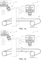
- FIG 1a shows an embodiment of the invention, in which a machine vision system 10 is disclosed in conjunction with two objects, a web 17a and machine clothing 17b.
- the machine vision system 10 comprises two lighting devices 18, 19 and two smart cameras 11, 14 comprising an image sensor 12, 15 and a data processing device 13, 16.
- Lighting devices 18, 19 illuminates the movable web 17a and the machine clothing 17b when the web 17a is not available.
- the image sensors 12, 15 are arranged to capture images from the movable web 17a and from the machine clothing 17b when the web 17a is not available and to transmit image data to the data processing device 13, 15 of the smart camera 11, 14.
- the data processing devices 13, 16 comprise at least one processor, at least one memory including computer program code for one or more program units, and means for receiving image data wirelessly or via wired connection from the image sensor 12, 15, for example, a receiver or a transceiver, and means for transmitting trigger signals wirelessly or via wired connection, for example, a transmitter or a transceiver.
- processors e.g. a general purpose processor and a graphics processor and a DSP processor and/or multiple different memories e.g. volatile memory for storing data and programs at run-time and nonvolatile memory such as a hard disk for permanently storing data and programs.
- the data processing device 13 of the smart camera 11 and the data processing device 16 of the smart camera 14 may be any computing device suitable for handling image data such as a computer.
- the data processing device 13 is in electronic communication with the image sensor 11 and the lighting device 18 via signal lines and the data processing device 16 is in electronic communication with the image sensor 12 and the lighting device 19 via signal lines.
- the lighting devices 18, 19 may also be integrated parts of the smart cameras 11, 14.
- the smart cameras 11, 14 may also include a video controller and an audio controller for generating signals that can be produced for the user with computer accessories.
- the smart cameras 11, 14 produce output to the user through output means.
- the video controller may be connected to a display.
- the display may be e.g. a flat panel display or a projector for producing a larger image.
- the audio controller may be connected to a sound source, such as loudspeakers or earphones.
- the smart cameras 11, 14 may also include an acoustic sensor such as a microphone.
- the image sensors 12, 15 are arranged to capture images of the web 17a and the lighting devices 18, 19 are illuminating the web 17a in the first operating mode.
- the data processing devices 13, 16 are configured to receive captured images as image data and analyse the image data in order to find deviations in the web 17a.
- the data processing devices 13, 16 analyse the image data. If the data processing device 13 detects from the image data that the web 17a is not on the machine clothing 17b, it may reconfigure the image sensors 12, 15 and the machine vision system 10 to a second operating mode.
- the data processing devices 13, 16 are still configured to receive images captured in the second operating mode as image data and analyse the image data in order to find deviations in the machine clothing 17b.
- the image sensors 12, 15 continue to capture images of the machine clothing 17b in the second operating mode.
- the image capturing frequency may be different or it may remain the same.
- the second image capturing frequency of the second operating mode may be, for example, higher than the first image capturing frequency of the first operating mode so that deviations in the machine clothing 17b can be more accurately imaged and detected. Deviations in the machine clothing 17b may be more difficult to detect, so there is a need to capture more images of the machine clothing 17b in order to enable more efficient monitoring of deviations in the machine clothing 17b.
- the lighting devices 18, 19 are arranged to illuminate the machine clothing 17b in the second operating mode, wherein the type of illumination of the second operating mode is different than the type of illumination of the first operating mode.
- Imaging of the machine clothing 17b in the second operating mode at the second image capturing frequency is shown in figure 1b .
- the need of the intensity of light of lighting devices 18, 19 may depend, for example, on the colour of the machine clothing 17b compared to the web 17a.
- the image sensors 12, 15 capture images from at least the whole machine clothing cycle, for example, at least from a marking 18 to the marking 18 i.e. until the marking 18 is detected twice in the images captured by image sensors 12, 15 by the data processing devices 13, 16.
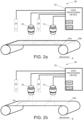
- FIG. 2a shows an embodiment of the invention, in which a machine vision system 20 is disclosed in conjunction with two objects, a web 23a and machine clothing 23b.
- the machine vision system 20 comprises at least two image sensors 21, 25, at least two lighting devices 24, 26 and a data processing device 22 for analysing image data captured by the at least two image sensors 21, 25.
- the image sensors 21, 25 are arranged to capture images from the moving object 23a that is a material web in a first operating mode and arranged to capture images from the second moving object 23b that is a machine clothing in a second operating mode and to transmit data of each image to the data processing device 22.
- the lighting devices 24, 26 are arranged to illuminate the moving objects 23a, 23b while imaging so that in both operating modes the illumination type being used is different.
- the data processing device 22 comprises at least one processor, at least one memory including computer program code for one or more program units, and means for receiving image data wirelessly or via a wired connection, for example, a receiver or a transceiver, and means for transmitting configurations by reconfiguration signals wirelessly or via a wired connection, for example, a transmitter or a transceiver, to the lighting devices 24, 26 and also possibly to the image sensors 21, 25.
- processors e.g. a general purpose processor and a graphics processor and a DSP processor, and/or multiple different memories e.g. volatile memory for storing data and programs at run-time, and nonvolatile memory such as a hard disk for permanently storing data and programs.
- the data processing device 22 may be any computing device suitable for handling image data, such as a computer.
- the data processing device 22 is in electronic communication with the image sensors 21, 25 and the lighting devices 24, 26 via signal lines.
- the data processing device 22 comprises I/O circuitry.
- the connection between the lighting devices 24, 26 and the data processing device 22 and the image sensors 21, 25 and the data processing device 22 is a wired or wireless network.
- the data processing device 22 may also include a video controller and an audio controller for generating signals that can be produced to the user with computer accessories.
- the video controller may be connected to a display.
- the display may be e.g. a flat panel display or a projector for producing a larger image.
- the audio controller may be connected to a sound source, such as loudspeakers or earphones.
- the data processing device 22 may also include an acoustic sensor, such as a microphone.
- the lighting devices 24, 26 may also be integrated parts of the camera sensors 21, 25.
- the data processing device 22 is configured to analyse the received images captured by the image sensors 21, 25 and if the data processing device 22 detects a deviation or a web break in the first operating mode or presence of a web in the second operating mode, it may indicate it for the process operator and/or transmit reconfiguration signals to at least one lighting device and possibly also to the image sensors.
- the image sensors 21, 25 are arranged to capture images of the web 23a and the lighting devices 24, 26 are illuminated the web 23a in the first operating mode.
- the data processing device 22 is configured to receive captured image as image data.
- the data processing device 22 is arranged to analyse the image data. If the data processing device 22 detects from the image data that the web 23a is not on the machine clothing 23b, it may reconfigure the image sensors 21, 25 and the lighting devices 24, 26 to a second operating mode for capturing images of the machine clothing 23b and illuminating the web machine clothing 23b.
- the data processing device 22 is configured to receive images captured in the second operating mode as image data and analyse the image data in order to find deviations in the machine clothing 23b.
- the image sensors 21, 25 are arranged to capture images of the machine clothing 23b in the second operating mode.
- the image capturing frequency may be different or it may remain the same compared to the first operating mode.
- the second image capturing frequency of the second operating mode may be, for example, higher than the first image capturing frequency of the first operating mode so that deviations in the machine clothing 23b can be more accurately imaged and detected or the second image capturing frequency may be the same in the first and in the second operating mode.
- the lighting devices 24, 26 may be arranged to illuminate the machine clothing 23b in the second operating mode, for example, more efficiently or less efficiently than in the first operating mode depending on the configurations. Imaging of the machine clothing 23b in the second operating mode at the second image capturing frequency is shown in figure 2b .
- the image sensors 21, 25 capture images from at least the whole machine clothing cycle of the machine clothing 23b, for example, at least from a seam 28 of the machine clothing 23b to seam 28 i.e. until the seam 28 is detected twice in the images captured by image sensors from the seam 28 by the data processing device 22.
- FIG 3a shows an embodiment of the invention, in which a machine vision system 30 is disclosed in conjunction with a machine clothing 33 as a moving object.
- the machine vision system 30 comprises an image sensor 31, a lighting device 34 and a data processing device 32 for analysing image data captured by the image sensor 31.
- the image sensor 31 is arranged to capture images from a material web (currently not on the machine clothing 33) in a first operating mode and arranged to capture images from the machine clothing 33 in a second operating mode and to transmit data of each image to the data processing device 32.
- the lighting device 34 is arranged to illuminate the machine clothing 33 (or the material web when available) while imaging so that in both operating modes the illumination type being used is different.
- the lighting device 34 may also be integrated parts of the camera sensor 31.
- the data processing device 32 is configured to analyse the received images captured by the image sensor 31.
- FIG. 3b shows an embodiment of the invention, in which a machine vision system 30 is disclosed in conjunction with a machine clothing 33 as a moving object.
- the machine vision system 30 comprises three image sensors 31a, 31b, 31c, a lighting device 34 and a data processing device 32 for analysing image data captured by the image sensors 31a, 31b, 31c arranged in parallel for imaging the whole width of the machine clothing 33 (and a material web when on the machine clothing 33).
- the image sensors 31a, 31b, 31c are arranged to capture images from the material web in a first operating mode and arranged to capture images from the machine clothing 33 in a second operating mode and to transmit data of each image to the data processing device 32.
- the lighting device 34 is arranged to illuminate the machine clothing 33 (or the material web when available) while imaging so that in both operating modes the illumination type being used is different.
- the lighting device 34 may also be an integrated part of a camera sensor.
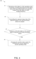
- FIG. 4 shows a monitoring method 40 of a machine vision system according to an example embodiment.
- the machine vision system comprises at least one lighting device, at least one image sensor and a data processing device.
- the machine vision system is monitoring a first object, for example, a material web in a first operating mode.
- a first operating mode the first object is illuminated by said at least one lighting device using a first type of illumination and images of the first object are captured by said at least one image sensor at a first imaging frequency, and wherein the first object is arranged at least partly on a second object.
- the second object may be, for example, a machine clothing.
- the captured image data of the captured images is transmitted to the data processing device for analysis.
- the machine vision system changes to monitor the second object in a second operating mode, if absence of the first object on the second object is detected by the data processing device in step 43.
- the second object in the second operating mode is illuminated by said at least one lighting device using a second type of illumination and images of the second object are captured by said at least one image sensor at a second imaging frequency, wherein the first type of illumination is different that the second type of illumination and the second imaging frequency is different than the first imaging frequency.
- the first type of illumination is the same than the second type of illumination or that the second imaging frequency is the same than the first imaging frequency.
- the various embodiments of the invention set out in the appended set of claims can be implemented with the help of computer program code that resides in a memory and causes an apparatus to carry out the embodiments of the invention set out in the appended set of claims.
- the apparatus that is a computing device, for example, a data processing device may comprise circuitry and electronics for analysing, receiving and transmitting data, a computer program code in a memory, and a processor which, when running the computer program code, causes the apparatus to carry out the features of an embodiment set out in the appended set of claims.
- the processor when running the computer program code, may carry out the steps of the following method: capturing image(s) of a first object by an image sensor, for example, a camera sensor, a first illumination in a first operating mode and capturing image(s) of a second object by the image sensor in a second illumination in a second operating mode, when absence of the first object is detected.
- an image sensor for example, a camera sensor
- first illumination in a first operating mode capturing image(s) of a second object by the image sensor in a second illumination in a second operating mode
- the present invention when compared to methods and systems of existing machine vision systems comprising at least an image sensor e.g. a camera suitable for capturing images.
- an image sensor e.g. a camera suitable for capturing images.
- the first mode comprises imaging at a first image capturing frequency at a first illumination
- the second mode comprises imaging at a second image capturing frequency at a second illumination, wherein the change of operating mode from the first mode to the second mode is performed, when it is detected that the first imaging target is unavailable and from the second mode to the first mode is performed, when it is detected that the first imaging target is available again.
Landscapes
- Engineering & Computer Science (AREA)
- Physics & Mathematics (AREA)
- General Physics & Mathematics (AREA)
- Textile Engineering (AREA)
- Life Sciences & Earth Sciences (AREA)
- Health & Medical Sciences (AREA)
- Chemical & Material Sciences (AREA)
- Analytical Chemistry (AREA)
- Biochemistry (AREA)
- General Health & Medical Sciences (AREA)
- Immunology (AREA)
- Pathology (AREA)
- Automation & Control Theory (AREA)
- Quality & Reliability (AREA)
- Wood Science & Technology (AREA)
- Manufacturing & Machinery (AREA)
- General Engineering & Computer Science (AREA)
- Medical Informatics (AREA)
- Artificial Intelligence (AREA)
- Computer Vision & Pattern Recognition (AREA)
- Evolutionary Computation (AREA)
- Software Systems (AREA)
- Spectroscopy & Molecular Physics (AREA)
- Investigating Materials By The Use Of Optical Means Adapted For Particular Applications (AREA)
- Treatment Of Fiber Materials (AREA)
- Length Measuring Devices By Optical Means (AREA)
- General Factory Administration (AREA)
- Testing, Inspecting, Measuring Of Stereoscopic Televisions And Televisions (AREA)
Applications Claiming Priority (3)
| Application Number | Priority Date | Filing Date | Title |
|---|---|---|---|
| FI20165387A FI128850B (en) | 2016-05-06 | 2016-05-06 | A machine vision method and system for monitoring manufacturing processes |
| PCT/FI2017/050325 WO2017191363A1 (en) | 2016-05-06 | 2017-04-28 | A machine vision method and system for monitoring manufacturing processes |
| EP17792559.1A EP3452811B1 (en) | 2016-05-06 | 2017-04-28 | A machine vision method and system for monitoring manufacturing processes |
Related Parent Applications (2)
| Application Number | Title | Priority Date | Filing Date |
|---|---|---|---|
| EP17792559.1A Division-Into EP3452811B1 (en) | 2016-05-06 | 2017-04-28 | A machine vision method and system for monitoring manufacturing processes |
| EP17792559.1A Division EP3452811B1 (en) | 2016-05-06 | 2017-04-28 | A machine vision method and system for monitoring manufacturing processes |
Publications (3)
| Publication Number | Publication Date |
|---|---|
| EP4019948A1 EP4019948A1 (en) | 2022-06-29 |
| EP4019948C0 EP4019948C0 (en) | 2024-09-18 |
| EP4019948B1 true EP4019948B1 (en) | 2024-09-18 |
Family
ID=60202816
Family Applications (2)
| Application Number | Title | Priority Date | Filing Date |
|---|---|---|---|
| EP22157040.1A Active EP4019948B1 (en) | 2016-05-06 | 2017-04-28 | A machine vision method and system for monitoring manufacturing processes |
| EP17792559.1A Active EP3452811B1 (en) | 2016-05-06 | 2017-04-28 | A machine vision method and system for monitoring manufacturing processes |
Family Applications After (1)
| Application Number | Title | Priority Date | Filing Date |
|---|---|---|---|
| EP17792559.1A Active EP3452811B1 (en) | 2016-05-06 | 2017-04-28 | A machine vision method and system for monitoring manufacturing processes |
Country Status (8)
| Country | Link |
|---|---|
| US (1) | US10884401B2 (enExample) |
| EP (2) | EP4019948B1 (enExample) |
| JP (1) | JP7090032B2 (enExample) |
| CN (1) | CN109416327B (enExample) |
| ES (1) | ES2923908T3 (enExample) |
| FI (1) | FI128850B (enExample) |
| PL (1) | PL3452811T3 (enExample) |
| WO (1) | WO2017191363A1 (enExample) |
Families Citing this family (14)
| Publication number | Priority date | Publication date | Assignee | Title |
|---|---|---|---|---|
| WO2019229919A1 (ja) * | 2018-05-31 | 2019-12-05 | 株式会社PSM International | 長尺シート材の品質計測方法および品質計測装置 |
| FI128235B (en) | 2018-12-10 | 2020-01-15 | Procemex Oy Ltd | Overhead sidelight |
| JP7269126B2 (ja) * | 2019-07-31 | 2023-05-08 | ファナック株式会社 | 撮像検出データの転送システム |
| US11920299B2 (en) | 2020-03-06 | 2024-03-05 | Ibs Of America | Formation detection system and a process of controlling |
| CN111650208B (zh) * | 2020-06-01 | 2021-08-27 | 东华大学 | 一种巡游式机织面料疵点在线检测器 |
| US20230213458A1 (en) * | 2021-12-30 | 2023-07-06 | CreateMe Technologies LLC | Automated inspection measurement in garment manufacturing |
| CN115201201B (zh) * | 2022-06-24 | 2023-08-01 | 广东工业大学 | 一种基于机器视觉的成形网面质量检测方法 |
| US12130249B2 (en) | 2022-08-03 | 2024-10-29 | Industrial Video Solutions Inc. | Systems and methods for monitoring and controlling industrial processes |
| US12169400B2 (en) | 2022-08-03 | 2024-12-17 | Industrial Video Solutions Inc. | Systems and methods for monitoring and controlling industrial processes |
| US12198438B2 (en) | 2022-08-03 | 2025-01-14 | Industrial Video Solutions Inc. | Systems and methods for monitoring and controlling industrial processes |
| US11846930B1 (en) | 2022-08-03 | 2023-12-19 | Industrial Video Solutions Inc. | Systems and methods for monitoring and controlling industrial processes |
| US12379717B2 (en) | 2022-08-03 | 2025-08-05 | Industrial Video Solutions Inc. | Systems and methods for monitoring and controlling industrial processes |
| US11932991B2 (en) * | 2022-08-03 | 2024-03-19 | Industrial Video Solutions Inc. | Systems and methods for monitoring and controlling industrial processes |
| CN117670993B (zh) * | 2023-12-06 | 2024-07-05 | 广东精英纺织服饰科技有限公司 | 一种基于机器视觉的纺织生产加工监控系统 |
Family Cites Families (30)
| Publication number | Priority date | Publication date | Assignee | Title |
|---|---|---|---|---|
| US4845374A (en) | 1987-07-20 | 1989-07-04 | R. J. Reynolds Tobacco Company | Method and apparatus for detecting the deposition of an adhesive on a travelling web |
| DE4216653C2 (de) * | 1992-05-20 | 1995-12-21 | Voith Gmbh J M | Abrißüberwachungseinrichtung für Papierbahnen |
| US5314072A (en) | 1992-09-02 | 1994-05-24 | Rutgers, The State University | Sorting plastic bottles for recycling |
| US5815198A (en) * | 1996-05-31 | 1998-09-29 | Vachtsevanos; George J. | Method and apparatus for analyzing an image to detect and identify defects |
| JP2000111483A (ja) * | 1998-10-02 | 2000-04-21 | Dainippon Printing Co Ltd | 周期性パターンの検査方法及び装置 |
| JP2000111493A (ja) | 1998-10-03 | 2000-04-21 | Kenji Shibahara | 表面状態検査方法 |
| US6158576A (en) | 1998-10-15 | 2000-12-12 | Albany International Corp. | Endless belt or fabric for use in process control loop |
| US6750466B2 (en) | 2001-02-09 | 2004-06-15 | Wintriss Engineering Corporation | Web inspection system |
| FI115588B (fi) * | 2001-11-02 | 2005-05-31 | Metso Automation Oy | Kameraliityntä |
| FI115163B (fi) | 2001-11-29 | 2005-03-15 | Metso Automation Oy | Spektrierottelevaan mittaukseen perustuva laadun- ja kunnonvalvonta |
| FI20025055A0 (fi) | 2002-03-27 | 2002-12-03 | Metso Paper Inc | Menetelmä paperi- tai kartonkikoneen radanhallinnassa |
| DE10249385A1 (de) | 2002-10-23 | 2004-05-06 | Voith Paper Patent Gmbh | Verfahren und Einrichtung zur Überwachung des Zustandes einer Bespannung |
| JP2004226328A (ja) | 2003-01-24 | 2004-08-12 | Hitachi Ltd | 外観検査システムおよびそれらを用いた品質評価システムおよび品質評価情報提供システム |
| DE10343517A1 (de) | 2003-09-19 | 2005-05-04 | Voith Paper Patent Gmbh | Verfahren und Anordnung zur Bestimmung der Wasserdurchlässigkeit einer Bespannung |
| FI118775B (fi) | 2005-05-12 | 2008-03-14 | Metso Paper Inc | Menetelmä ja laite kenkätelan kunnonvalvonnassa |
| FI119708B (fi) * | 2006-02-01 | 2009-02-13 | Viconsys Oy | Laite rainan tarkkailemiseksi |
| EP1987349A4 (en) | 2006-02-22 | 2013-12-18 | Metso Automation Oy | METHOD FOR OBSERVING A FASTLY MOVING PAPER TRACK AND CORRESPONDING SYSTEM |
| DE102006055823A1 (de) | 2006-11-27 | 2008-05-29 | Voith Patent Gmbh | Verfahren zur Erfassung eines Abrisses einer Faserstoffbahn in einer Trockenpartie einer Maschine zur Herstellung der Faserstoffbahn und Trockensieb zur Durchführung des Verfahrens |
| WO2008107892A1 (en) | 2007-03-06 | 2008-09-12 | Advanced Vision Technology (Avt) Ltd. | System and method for detecting the contour of an object on a moving conveyor belt |
| US20090028417A1 (en) | 2007-07-26 | 2009-01-29 | 3M Innovative Properties Company | Fiducial marking for multi-unit process spatial synchronization |
| DE102007045895A1 (de) * | 2007-09-26 | 2009-04-09 | Voith Patent Gmbh | Bandkalandervorrichtung und Verfahren zum Betrieb einer Bandkalandervorrichtung |
| US7986410B2 (en) * | 2008-03-18 | 2011-07-26 | Voith Patent Gmbh | Method for detecting a fibrous web tear in a drying section of a machine for producing the fibrous web and apparatus for performing said method |
| FI20106053A0 (fi) | 2010-10-13 | 2010-10-13 | Metso Automation Oy | Järjestelmä rainan tarkkailemiseksi ja vastaava menetelmä rainan tarkkailemiseksi |
| DE102011078010A1 (de) * | 2011-06-22 | 2012-12-27 | Voith Patent Gmbh | Überwachung einer Bespannung |
| US8591703B2 (en) | 2011-07-06 | 2013-11-26 | Voith Patent Gmbh | Monofilament yarn for a paper machine clothing fabric |
| CN202221415U (zh) | 2011-09-03 | 2012-05-16 | 山东轻工业学院 | 宽幅面纸张表面缺陷在线检测系统 |
| DE102011113670A1 (de) | 2011-09-20 | 2013-03-21 | Schott Ag | Beleuchtungsvorrichtung, Inspektionsvorrichtung und Inspektionsverfahren für die optische Prüfung eines Objekts |
| FI125725B (fi) * | 2011-11-15 | 2016-01-29 | Valmet Technologies Oy | Menetelmä ja sovitelma kuiturainan seuraamiseksi |
| DE102012208201A1 (de) * | 2012-05-16 | 2013-11-21 | Voith Patent Gmbh | Verfahren zur Erfassung von Verschmutzung einer Papiermaschinenbespannung |
| FI128403B (en) | 2013-07-05 | 2020-04-30 | Procemex Oy Ltd | Synchronizing image capture |
-
2016
- 2016-05-06 FI FI20165387A patent/FI128850B/en active IP Right Grant
-
2017
- 2017-04-28 PL PL17792559.1T patent/PL3452811T3/pl unknown
- 2017-04-28 US US16/095,790 patent/US10884401B2/en active Active
- 2017-04-28 EP EP22157040.1A patent/EP4019948B1/en active Active
- 2017-04-28 EP EP17792559.1A patent/EP3452811B1/en active Active
- 2017-04-28 CN CN201780028058.9A patent/CN109416327B/zh active Active
- 2017-04-28 JP JP2018558234A patent/JP7090032B2/ja active Active
- 2017-04-28 WO PCT/FI2017/050325 patent/WO2017191363A1/en not_active Ceased
- 2017-04-28 ES ES17792559T patent/ES2923908T3/es active Active
Also Published As
| Publication number | Publication date |
|---|---|
| FI20165387A7 (fi) | 2017-11-07 |
| WO2017191363A1 (en) | 2017-11-09 |
| JP2019518943A (ja) | 2019-07-04 |
| JP7090032B2 (ja) | 2022-06-23 |
| EP3452811A1 (en) | 2019-03-13 |
| FI128850B (en) | 2021-01-29 |
| CN109416327B (zh) | 2021-10-26 |
| US20190129396A1 (en) | 2019-05-02 |
| CN109416327A (zh) | 2019-03-01 |
| EP3452811B1 (en) | 2022-05-25 |
| EP3452811A4 (en) | 2020-01-22 |
| ES2923908T3 (es) | 2022-10-03 |
| EP4019948C0 (en) | 2024-09-18 |
| PL3452811T3 (pl) | 2022-10-10 |
| EP4019948A1 (en) | 2022-06-29 |
| US10884401B2 (en) | 2021-01-05 |
Similar Documents
| Publication | Publication Date | Title |
|---|---|---|
| EP4019948B1 (en) | A machine vision method and system for monitoring manufacturing processes | |
| JP5195004B2 (ja) | 走行糸条の検査方法、および、それを用いた炭素繊維の製造方法 | |
| KR100364936B1 (ko) | 감시 장치 | |
| JP6828652B2 (ja) | 衛生用紙の製造方法及び欠陥検査装置 | |
| JP2019518943A5 (enExample) | ||
| US10451562B2 (en) | Machine vision method and system | |
| US9701506B2 (en) | Monitoring system and apparatus comprising such a monitoring system | |
| US9532015B2 (en) | Synchronization of imaging | |
| US20210348334A1 (en) | Monitoring system | |
| WO2023038017A1 (ja) | 欠点分類システム | |
| FI128820B (en) | Procedure for computer vision and systems for monitoring manufacturing processes | |
| JP4903031B2 (ja) | 透光性を有するシート材の外観検査装置および方法 | |
| EP3667302A1 (en) | Overhead sidelight | |
| JP2020107605A5 (enExample) | ||
| CN119908113A (zh) | 用于检测物体的不规则性的系统和方法 | |
| JP2011209111A (ja) | 紙カップの検査装置及びその方法 | |
| JP2024160802A (ja) | 欠陥検出装置 |
Legal Events
| Date | Code | Title | Description |
|---|---|---|---|
| PUAI | Public reference made under article 153(3) epc to a published international application that has entered the european phase |
Free format text: ORIGINAL CODE: 0009012 |
|
| STAA | Information on the status of an ep patent application or granted ep patent |
Free format text: STATUS: THE APPLICATION HAS BEEN PUBLISHED |
|
| AC | Divisional application: reference to earlier application |
Ref document number: 3452811 Country of ref document: EP Kind code of ref document: P |
|
| AK | Designated contracting states |
Kind code of ref document: A1 Designated state(s): AL AT BE BG CH CY CZ DE DK EE ES FI FR GB GR HR HU IE IS IT LI LT LU LV MC MK MT NL NO PL PT RO RS SE SI SK SM TR |
|
| STAA | Information on the status of an ep patent application or granted ep patent |
Free format text: STATUS: REQUEST FOR EXAMINATION WAS MADE |
|
| 17P | Request for examination filed |
Effective date: 20220815 |
|
| RBV | Designated contracting states (corrected) |
Designated state(s): AL AT BE BG CH CY CZ DE DK EE ES FI FR GB GR HR HU IE IS IT LI LT LU LV MC MK MT NL NO PL PT RO RS SE SI SK SM TR |
|
| REG | Reference to a national code |
Ref country code: DE Ref legal event code: R079 Free format text: PREVIOUS MAIN CLASS: G01N0021890000 Ipc: D21F0001000000 Ref country code: DE Ref legal event code: R079 Ref document number: 602017085013 Country of ref document: DE Free format text: PREVIOUS MAIN CLASS: G01N0021890000 Ipc: D21F0001000000 |
|
| GRAP | Despatch of communication of intention to grant a patent |
Free format text: ORIGINAL CODE: EPIDOSNIGR1 |
|
| STAA | Information on the status of an ep patent application or granted ep patent |
Free format text: STATUS: GRANT OF PATENT IS INTENDED |
|
| RIC1 | Information provided on ipc code assigned before grant |
Ipc: G05B 23/02 20060101ALI20240408BHEP Ipc: G05B 19/418 20060101ALI20240408BHEP Ipc: G01N 21/88 20060101ALI20240408BHEP Ipc: G01N 21/898 20060101ALI20240408BHEP Ipc: G01N 21/89 20060101ALI20240408BHEP Ipc: D21G 9/00 20060101ALI20240408BHEP Ipc: D21F 7/04 20060101ALI20240408BHEP Ipc: D21F 1/00 20060101AFI20240408BHEP |
|
| INTG | Intention to grant announced |
Effective date: 20240503 |
|
| GRAS | Grant fee paid |
Free format text: ORIGINAL CODE: EPIDOSNIGR3 |
|
| GRAA | (expected) grant |
Free format text: ORIGINAL CODE: 0009210 |
|
| STAA | Information on the status of an ep patent application or granted ep patent |
Free format text: STATUS: THE PATENT HAS BEEN GRANTED |
|
| AC | Divisional application: reference to earlier application |
Ref document number: 3452811 Country of ref document: EP Kind code of ref document: P |
|
| AK | Designated contracting states |
Kind code of ref document: B1 Designated state(s): AL AT BE BG CH CY CZ DE DK EE ES FI FR GB GR HR HU IE IS IT LI LT LU LV MC MK MT NL NO PL PT RO RS SE SI SK SM TR |
|
| REG | Reference to a national code |
Ref country code: GB Ref legal event code: FG4D |
|
| REG | Reference to a national code |
Ref country code: CH Ref legal event code: EP |
|
| REG | Reference to a national code |
Ref country code: DE Ref legal event code: R096 Ref document number: 602017085013 Country of ref document: DE |
|
| REG | Reference to a national code |
Ref country code: IE Ref legal event code: FG4D |
|
| U01 | Request for unitary effect filed |
Effective date: 20241014 |
|
| U07 | Unitary effect registered |
Designated state(s): AT BE BG DE DK EE FI FR IT LT LU LV MT NL PT RO SE SI Effective date: 20241030 |
|
| PG25 | Lapsed in a contracting state [announced via postgrant information from national office to epo] |
Ref country code: NO Free format text: LAPSE BECAUSE OF FAILURE TO SUBMIT A TRANSLATION OF THE DESCRIPTION OR TO PAY THE FEE WITHIN THE PRESCRIBED TIME-LIMIT Effective date: 20241218 |
|
| PG25 | Lapsed in a contracting state [announced via postgrant information from national office to epo] |
Ref country code: GR Free format text: LAPSE BECAUSE OF FAILURE TO SUBMIT A TRANSLATION OF THE DESCRIPTION OR TO PAY THE FEE WITHIN THE PRESCRIBED TIME-LIMIT Effective date: 20241219 |
|
| PG25 | Lapsed in a contracting state [announced via postgrant information from national office to epo] |
Ref country code: HR Free format text: LAPSE BECAUSE OF FAILURE TO SUBMIT A TRANSLATION OF THE DESCRIPTION OR TO PAY THE FEE WITHIN THE PRESCRIBED TIME-LIMIT Effective date: 20240918 |
|
| PG25 | Lapsed in a contracting state [announced via postgrant information from national office to epo] |
Ref country code: RS Free format text: LAPSE BECAUSE OF FAILURE TO SUBMIT A TRANSLATION OF THE DESCRIPTION OR TO PAY THE FEE WITHIN THE PRESCRIBED TIME-LIMIT Effective date: 20241218 |
|
| PG25 | Lapsed in a contracting state [announced via postgrant information from national office to epo] |
Ref country code: RS Free format text: LAPSE BECAUSE OF FAILURE TO SUBMIT A TRANSLATION OF THE DESCRIPTION OR TO PAY THE FEE WITHIN THE PRESCRIBED TIME-LIMIT Effective date: 20241218 Ref country code: NO Free format text: LAPSE BECAUSE OF FAILURE TO SUBMIT A TRANSLATION OF THE DESCRIPTION OR TO PAY THE FEE WITHIN THE PRESCRIBED TIME-LIMIT Effective date: 20241218 Ref country code: HR Free format text: LAPSE BECAUSE OF FAILURE TO SUBMIT A TRANSLATION OF THE DESCRIPTION OR TO PAY THE FEE WITHIN THE PRESCRIBED TIME-LIMIT Effective date: 20240918 Ref country code: GR Free format text: LAPSE BECAUSE OF FAILURE TO SUBMIT A TRANSLATION OF THE DESCRIPTION OR TO PAY THE FEE WITHIN THE PRESCRIBED TIME-LIMIT Effective date: 20241219 |
|
| PG25 | Lapsed in a contracting state [announced via postgrant information from national office to epo] |
Ref country code: IS Free format text: LAPSE BECAUSE OF FAILURE TO SUBMIT A TRANSLATION OF THE DESCRIPTION OR TO PAY THE FEE WITHIN THE PRESCRIBED TIME-LIMIT Effective date: 20250118 |
|
| PG25 | Lapsed in a contracting state [announced via postgrant information from national office to epo] |
Ref country code: SM Free format text: LAPSE BECAUSE OF FAILURE TO SUBMIT A TRANSLATION OF THE DESCRIPTION OR TO PAY THE FEE WITHIN THE PRESCRIBED TIME-LIMIT Effective date: 20240918 |
|
| PG25 | Lapsed in a contracting state [announced via postgrant information from national office to epo] |
Ref country code: ES Free format text: LAPSE BECAUSE OF FAILURE TO SUBMIT A TRANSLATION OF THE DESCRIPTION OR TO PAY THE FEE WITHIN THE PRESCRIBED TIME-LIMIT Effective date: 20240918 |
|
| PG25 | Lapsed in a contracting state [announced via postgrant information from national office to epo] |
Ref country code: CZ Free format text: LAPSE BECAUSE OF FAILURE TO SUBMIT A TRANSLATION OF THE DESCRIPTION OR TO PAY THE FEE WITHIN THE PRESCRIBED TIME-LIMIT Effective date: 20240918 Ref country code: PL Free format text: LAPSE BECAUSE OF FAILURE TO SUBMIT A TRANSLATION OF THE DESCRIPTION OR TO PAY THE FEE WITHIN THE PRESCRIBED TIME-LIMIT Effective date: 20240918 |
|
| PG25 | Lapsed in a contracting state [announced via postgrant information from national office to epo] |
Ref country code: SK Free format text: LAPSE BECAUSE OF FAILURE TO SUBMIT A TRANSLATION OF THE DESCRIPTION OR TO PAY THE FEE WITHIN THE PRESCRIBED TIME-LIMIT Effective date: 20240918 |
|
| U20 | Renewal fee for the european patent with unitary effect paid |
Year of fee payment: 9 Effective date: 20250402 |
|
| PLBE | No opposition filed within time limit |
Free format text: ORIGINAL CODE: 0009261 |
|
| STAA | Information on the status of an ep patent application or granted ep patent |
Free format text: STATUS: NO OPPOSITION FILED WITHIN TIME LIMIT |
|
| 26N | No opposition filed |
Effective date: 20250619 |
|
| REG | Reference to a national code |
Ref country code: CH Ref legal event code: H13 Free format text: ST27 STATUS EVENT CODE: U-0-0-H10-H13 (AS PROVIDED BY THE NATIONAL OFFICE) Effective date: 20251125 |