EP3452811B1 - A machine vision method and system for monitoring manufacturing processes - Google Patents
A machine vision method and system for monitoring manufacturing processes Download PDFInfo
- Publication number
- EP3452811B1 EP3452811B1 EP17792559.1A EP17792559A EP3452811B1 EP 3452811 B1 EP3452811 B1 EP 3452811B1 EP 17792559 A EP17792559 A EP 17792559A EP 3452811 B1 EP3452811 B1 EP 3452811B1
- Authority
- EP
- European Patent Office
- Prior art keywords
- operating mode
- machine
- data processing
- processing device
- machine clothing
- Prior art date
- Legal status (The legal status is an assumption and is not a legal conclusion. Google has not performed a legal analysis and makes no representation as to the accuracy of the status listed.)
- Active
Links
- 238000000034 method Methods 0.000 title claims description 24
- 238000012544 monitoring process Methods 0.000 title claims description 14
- 238000004519 manufacturing process Methods 0.000 title description 4
- 238000005286 illumination Methods 0.000 claims description 32
- 239000000463 material Substances 0.000 claims description 27
- 238000004458 analytical method Methods 0.000 claims description 12
- 238000004590 computer program Methods 0.000 claims description 10
- 230000003247 decreasing effect Effects 0.000 claims description 3
- 238000003384 imaging method Methods 0.000 description 37
- 230000015654 memory Effects 0.000 description 10
- 229920002522 Wood fibre Polymers 0.000 description 3
- 238000004891 communication Methods 0.000 description 3
- 230000007547 defect Effects 0.000 description 3
- 239000004744 fabric Substances 0.000 description 3
- 239000000123 paper Substances 0.000 description 3
- 239000011111 cardboard Substances 0.000 description 2
- 229920002678 cellulose Polymers 0.000 description 2
- 239000001913 cellulose Substances 0.000 description 2
- 125000004122 cyclic group Chemical group 0.000 description 2
- 238000006243 chemical reaction Methods 0.000 description 1
- 239000000835 fiber Substances 0.000 description 1
- 239000011159 matrix material Substances 0.000 description 1
- 239000000126 substance Substances 0.000 description 1
- 239000004753 textile Substances 0.000 description 1
- 230000037303 wrinkles Effects 0.000 description 1
Images


Classifications
-
- G—PHYSICS
- G01—MEASURING; TESTING
- G01N—INVESTIGATING OR ANALYSING MATERIALS BY DETERMINING THEIR CHEMICAL OR PHYSICAL PROPERTIES
- G01N21/00—Investigating or analysing materials by the use of optical means, i.e. using sub-millimetre waves, infrared, visible or ultraviolet light
- G01N21/17—Systems in which incident light is modified in accordance with the properties of the material investigated
- G01N21/25—Colour; Spectral properties, i.e. comparison of effect of material on the light at two or more different wavelengths or wavelength bands
-
- G—PHYSICS
- G05—CONTROLLING; REGULATING
- G05B—CONTROL OR REGULATING SYSTEMS IN GENERAL; FUNCTIONAL ELEMENTS OF SUCH SYSTEMS; MONITORING OR TESTING ARRANGEMENTS FOR SUCH SYSTEMS OR ELEMENTS
- G05B19/00—Programme-control systems
- G05B19/02—Programme-control systems electric
- G05B19/418—Total factory control, i.e. centrally controlling a plurality of machines, e.g. direct or distributed numerical control [DNC], flexible manufacturing systems [FMS], integrated manufacturing systems [IMS], computer integrated manufacturing [CIM]
- G05B19/41875—Total factory control, i.e. centrally controlling a plurality of machines, e.g. direct or distributed numerical control [DNC], flexible manufacturing systems [FMS], integrated manufacturing systems [IMS], computer integrated manufacturing [CIM] characterised by quality surveillance of production
-
- D—TEXTILES; PAPER
- D21—PAPER-MAKING; PRODUCTION OF CELLULOSE
- D21F—PAPER-MAKING MACHINES; METHODS OF PRODUCING PAPER THEREON
- D21F1/00—Wet end of machines for making continuous webs of paper
- D21F1/0027—Screen-cloths
-
- D—TEXTILES; PAPER
- D21—PAPER-MAKING; PRODUCTION OF CELLULOSE
- D21F—PAPER-MAKING MACHINES; METHODS OF PRODUCING PAPER THEREON
- D21F7/00—Other details of machines for making continuous webs of paper
- D21F7/04—Paper-break control devices
-
- D—TEXTILES; PAPER
- D21—PAPER-MAKING; PRODUCTION OF CELLULOSE
- D21G—CALENDERS; ACCESSORIES FOR PAPER-MAKING MACHINES
- D21G9/00—Other accessories for paper-making machines
- D21G9/0009—Paper-making control systems
-
- G—PHYSICS
- G01—MEASURING; TESTING
- G01N—INVESTIGATING OR ANALYSING MATERIALS BY DETERMINING THEIR CHEMICAL OR PHYSICAL PROPERTIES
- G01N21/00—Investigating or analysing materials by the use of optical means, i.e. using sub-millimetre waves, infrared, visible or ultraviolet light
- G01N21/17—Systems in which incident light is modified in accordance with the properties of the material investigated
-
- G—PHYSICS
- G01—MEASURING; TESTING
- G01N—INVESTIGATING OR ANALYSING MATERIALS BY DETERMINING THEIR CHEMICAL OR PHYSICAL PROPERTIES
- G01N21/00—Investigating or analysing materials by the use of optical means, i.e. using sub-millimetre waves, infrared, visible or ultraviolet light
- G01N21/84—Systems specially adapted for particular applications
- G01N21/88—Investigating the presence of flaws or contamination
- G01N21/89—Investigating the presence of flaws or contamination in moving material, e.g. running paper or textiles
- G01N21/8901—Optical details; Scanning details
-
- G—PHYSICS
- G01—MEASURING; TESTING
- G01N—INVESTIGATING OR ANALYSING MATERIALS BY DETERMINING THEIR CHEMICAL OR PHYSICAL PROPERTIES
- G01N21/00—Investigating or analysing materials by the use of optical means, i.e. using sub-millimetre waves, infrared, visible or ultraviolet light
- G01N21/84—Systems specially adapted for particular applications
- G01N21/88—Investigating the presence of flaws or contamination
- G01N21/89—Investigating the presence of flaws or contamination in moving material, e.g. running paper or textiles
- G01N21/892—Investigating the presence of flaws or contamination in moving material, e.g. running paper or textiles characterised by the flaw, defect or object feature examined
- G01N21/898—Irregularities in textured or patterned surfaces, e.g. textiles, wood
- G01N21/8983—Irregularities in textured or patterned surfaces, e.g. textiles, wood for testing textile webs, i.e. woven material
-
- G—PHYSICS
- G05—CONTROLLING; REGULATING
- G05B—CONTROL OR REGULATING SYSTEMS IN GENERAL; FUNCTIONAL ELEMENTS OF SUCH SYSTEMS; MONITORING OR TESTING ARRANGEMENTS FOR SUCH SYSTEMS OR ELEMENTS
- G05B13/00—Adaptive control systems, i.e. systems automatically adjusting themselves to have a performance which is optimum according to some preassigned criterion
- G05B13/02—Adaptive control systems, i.e. systems automatically adjusting themselves to have a performance which is optimum according to some preassigned criterion electric
-
- G—PHYSICS
- G05—CONTROLLING; REGULATING
- G05B—CONTROL OR REGULATING SYSTEMS IN GENERAL; FUNCTIONAL ELEMENTS OF SUCH SYSTEMS; MONITORING OR TESTING ARRANGEMENTS FOR SUCH SYSTEMS OR ELEMENTS
- G05B19/00—Programme-control systems
- G05B19/02—Programme-control systems electric
- G05B19/418—Total factory control, i.e. centrally controlling a plurality of machines, e.g. direct or distributed numerical control [DNC], flexible manufacturing systems [FMS], integrated manufacturing systems [IMS], computer integrated manufacturing [CIM]
- G05B19/4184—Total factory control, i.e. centrally controlling a plurality of machines, e.g. direct or distributed numerical control [DNC], flexible manufacturing systems [FMS], integrated manufacturing systems [IMS], computer integrated manufacturing [CIM] characterised by fault tolerance, reliability of production system
-
- G—PHYSICS
- G05—CONTROLLING; REGULATING
- G05B—CONTROL OR REGULATING SYSTEMS IN GENERAL; FUNCTIONAL ELEMENTS OF SUCH SYSTEMS; MONITORING OR TESTING ARRANGEMENTS FOR SUCH SYSTEMS OR ELEMENTS
- G05B23/00—Testing or monitoring of control systems or parts thereof
- G05B23/02—Electric testing or monitoring
- G05B23/0205—Electric testing or monitoring by means of a monitoring system capable of detecting and responding to faults
- G05B23/0259—Electric testing or monitoring by means of a monitoring system capable of detecting and responding to faults characterized by the response to fault detection
- G05B23/0297—Reconfiguration of monitoring system, e.g. use of virtual sensors; change monitoring method as a response to monitoring results
-
- G—PHYSICS
- G01—MEASURING; TESTING
- G01N—INVESTIGATING OR ANALYSING MATERIALS BY DETERMINING THEIR CHEMICAL OR PHYSICAL PROPERTIES
- G01N21/00—Investigating or analysing materials by the use of optical means, i.e. using sub-millimetre waves, infrared, visible or ultraviolet light
- G01N21/84—Systems specially adapted for particular applications
- G01N21/88—Investigating the presence of flaws or contamination
- G01N21/8851—Scan or image signal processing specially adapted therefor, e.g. for scan signal adjustment, for detecting different kinds of defects, for compensating for structures, markings, edges
- G01N2021/8854—Grading and classifying of flaws
- G01N2021/8867—Grading and classifying of flaws using sequentially two or more inspection runs, e.g. coarse and fine, or detecting then analysing
-
- G—PHYSICS
- G01—MEASURING; TESTING
- G01N—INVESTIGATING OR ANALYSING MATERIALS BY DETERMINING THEIR CHEMICAL OR PHYSICAL PROPERTIES
- G01N21/00—Investigating or analysing materials by the use of optical means, i.e. using sub-millimetre waves, infrared, visible or ultraviolet light
- G01N21/84—Systems specially adapted for particular applications
- G01N21/88—Investigating the presence of flaws or contamination
- G01N21/89—Investigating the presence of flaws or contamination in moving material, e.g. running paper or textiles
- G01N21/8901—Optical details; Scanning details
- G01N21/8903—Optical details; Scanning details using a multiple detector array
-
- G—PHYSICS
- G05—CONTROLLING; REGULATING
- G05B—CONTROL OR REGULATING SYSTEMS IN GENERAL; FUNCTIONAL ELEMENTS OF SUCH SYSTEMS; MONITORING OR TESTING ARRANGEMENTS FOR SUCH SYSTEMS OR ELEMENTS
- G05B2219/00—Program-control systems
- G05B2219/30—Nc systems
- G05B2219/31—From computer integrated manufacturing till monitoring
- G05B2219/31446—Detect if workpiece, object present
-
- G—PHYSICS
- G05—CONTROLLING; REGULATING
- G05B—CONTROL OR REGULATING SYSTEMS IN GENERAL; FUNCTIONAL ELEMENTS OF SUCH SYSTEMS; MONITORING OR TESTING ARRANGEMENTS FOR SUCH SYSTEMS OR ELEMENTS
- G05B2219/00—Program-control systems
- G05B2219/30—Nc systems
- G05B2219/31—From computer integrated manufacturing till monitoring
- G05B2219/31455—Monitor process status
-
- G—PHYSICS
- G05—CONTROLLING; REGULATING
- G05B—CONTROL OR REGULATING SYSTEMS IN GENERAL; FUNCTIONAL ELEMENTS OF SUCH SYSTEMS; MONITORING OR TESTING ARRANGEMENTS FOR SUCH SYSTEMS OR ELEMENTS
- G05B2219/00—Program-control systems
- G05B2219/30—Nc systems
- G05B2219/37—Measurements
- G05B2219/37555—Camera detects orientation, position workpiece, points of workpiece
-
- G—PHYSICS
- G05—CONTROLLING; REGULATING
- G05B—CONTROL OR REGULATING SYSTEMS IN GENERAL; FUNCTIONAL ELEMENTS OF SUCH SYSTEMS; MONITORING OR TESTING ARRANGEMENTS FOR SUCH SYSTEMS OR ELEMENTS
- G05B2219/00—Program-control systems
- G05B2219/30—Nc systems
- G05B2219/37—Measurements
- G05B2219/37572—Camera, tv, vision
-
- G—PHYSICS
- G05—CONTROLLING; REGULATING
- G05B—CONTROL OR REGULATING SYSTEMS IN GENERAL; FUNCTIONAL ELEMENTS OF SUCH SYSTEMS; MONITORING OR TESTING ARRANGEMENTS FOR SUCH SYSTEMS OR ELEMENTS
- G05B2219/00—Program-control systems
- G05B2219/30—Nc systems
- G05B2219/45—Nc applications
- G05B2219/45196—Textile, embroidery, stitching machine
-
- G—PHYSICS
- G05—CONTROLLING; REGULATING
- G05B—CONTROL OR REGULATING SYSTEMS IN GENERAL; FUNCTIONAL ELEMENTS OF SUCH SYSTEMS; MONITORING OR TESTING ARRANGEMENTS FOR SUCH SYSTEMS OR ELEMENTS
- G05B2219/00—Program-control systems
- G05B2219/30—Nc systems
- G05B2219/45—Nc applications
- G05B2219/45222—Cloth making
-
- Y—GENERAL TAGGING OF NEW TECHNOLOGICAL DEVELOPMENTS; GENERAL TAGGING OF CROSS-SECTIONAL TECHNOLOGIES SPANNING OVER SEVERAL SECTIONS OF THE IPC; TECHNICAL SUBJECTS COVERED BY FORMER USPC CROSS-REFERENCE ART COLLECTIONS [XRACs] AND DIGESTS
- Y02—TECHNOLOGIES OR APPLICATIONS FOR MITIGATION OR ADAPTATION AGAINST CLIMATE CHANGE
- Y02P—CLIMATE CHANGE MITIGATION TECHNOLOGIES IN THE PRODUCTION OR PROCESSING OF GOODS
- Y02P90/00—Enabling technologies with a potential contribution to greenhouse gas [GHG] emissions mitigation
- Y02P90/02—Total factory control, e.g. smart factories, flexible manufacturing systems [FMS] or integrated manufacturing systems [IMS]
Definitions
- the present invention relates to a method for imaging of continuous manufacturing processes, in which method a camera is used for imaging and a lighting device is used for illuminating a continuous product and fabrics under the continuous product.
- the invention also relates to a system and a computer program product causing a system to carry out the method.
- JP 2000111483 A discloses a method and an apparatus in which a cyclic pattern is inspected from a continuous cyclic pattern product.
- the apparatus comprises a line sensor camera, a light source which is arranged to face the camera, an upstream-side belt conveyor and a downstream-side belt conveyor by which an object to be inspected is moved between the camera and the light source.
- an image processor is provided. When the product is absent, the scan rate is set lower,
- EP 1 925 725 A1 and US 5,590,577 disclose systems for detecting tear of a material web being arranged on a machine clothing.
- said at least one lighting device in the second operating mode is reconfigured to use a second type of illumination for illuminating the second object to be monitored.
- said at least one camera sensor in the second operating mode is reconfigured to capture images at a second image capturing frequency from the second object to be monitored.
- image analysing parameters of the data processing device are reconfigured for detecting deviations from the second object to be monitor.
- the absence of the first object on the second object is detected by the data processing device from captured image data.
- the absence is detected from a received external indication signal.
- the first object is a material web and the second object is a machine clothing.
- the method further comprises: changing the machine vision system for monitoring in the first operating mode, if presence of the first object on the second object is detected in the second operating mode by the data processing device.
- said at least one lighting device in the second operating mode is reconfigured to use a second type of illumination for illuminating the second object to be monitored.
- said at least one camera sensor in the second operating mode is reconfigured to capture images at a second image capturing frequency from the second object to be monitored.
- image analysing parameters of the data processing device are reconfigured for detecting deviations from the second object to be monitored.
- the absence of the first object on the second object is detected by the data processing device from captured image data. According to an example outside the claimed invention said absence may be detected from a received external indication signal.
- the first object is a material web and the second object is a machine clothing.
- the method further comprises: changing the machine vision system for monitoring the first object in the first operating mode, if presence of the first object on the second object is detected in the second operating mode by the data processing device.
- said at least one lighting device in the second operating mode is reconfigured to use a second type of illumination for illuminating the second object to be monitored.
- said at least one camera sensor in the second operating mode is reconfigured to capture images at a second image capturing frequency from the second object to be monitor.
- image analysing parameters of the data processing device are reconfigured for detecting deviations from the second object to be monitored.
- the absence of the first object on the second object is detected by the data processing device from captured image data.
- the absence is detected from a received external indication signal.
- the first object is a material web and the second object is a machine clothing.
- the method further comprises: changing the machine vision system for monitoring in the first operating mode, if presence of the first object on the second object is detected in the second operating mode by the data processing device.
- the present invention relates to a machine vision system according to example embodiments having two different operating modes for two different objects and comprising at least one image sensor used for imaging a web product and machine clothing and at least one lighting device for illuminating the web product and the machine clothing.
- the web product is a first object and it is imaged and illuminated in the first operating mode of the machine vision system.
- the machine clothing is the second object and it is imaged and illuminated in the second operating mode of the machine vision system.
- web product refers in this context to any type of a wood fibre web.
- wood fibre refers in this context to any suitable wood fibre webs, for example, paper, cellulose or cardboard webs.
- machine clothing refers in this context to any type of fabric used, for example, in a paper, cardboard of cellulose machine/machinery for dewatering and/or transporting the web product. It may be, for example, a woven textile belt of felt.
- the web product and the machine clothing is illuminated and imaged in order to find web deviations from the web product and clothing deviations from the machine clothing.
- web deviation includes in this context any deviation detectable from the web product, for example, a defect, a hole, a stain, a definite change, a grey or dark spot, a streak, a wrinkle, an air bubble or a pattern in a web.
- clothing deviation includes in this context any deviation detectable from the machine clothing, for example, a defect, a hole, or a risen yarn etc. that may possibly cause machine clothing-related web defect(s). Machine clothing contributes to product quality, fibre and chemical conversion efficiency, and production speed.
- a machine vision system comprises at least one image sensor, at least one lighting device and data processing device.
- the image sensor is used for capturing images of at least two different kinds of objects, being a web and machine clothing and the lighting device is used for lighting the objects arranged to be imaged.
- the machine vision system has at least two different operating modes, wherein each mode is arranged to be suitable for a certain target: a first operating mode for the web product and the second operating mode for the machine clothing. Different operating modes may-have different lighting and also the imaging frequency is different.
- the operating mode may be selected on basis of the imaging target for enabling effective detecting of errors from both objects.
- the operating mode being used depends on the object.
- the first operating mode the first object, the web product, is illuminated by a first type of illumination and images of the first object is captured at a first imaging frequency and in the second operating mode the second object, the machine clothing, are illuminated by a second type of illumination and images of the first object are continued to be captured at the first imaging frequency but possibly it is changed to the second imaging frequency.
- a camera sensor of the machine vision system detects the absence of the web or, according to an example outside the claimed invention, an external indication signal about the web break is transmitted to the machine vision system, for example, from a paper machine control system, the first operating mode of the machine vision system used for imaging and illuminating the web product is arranged to be changed to the second operating mode for imaging and illuminating the machine clothing.
- a second mode reconfiguration signal is at least transmitted to at least one lighting device for reconfiguring the at least one lighting device to the second operating mode. It is also possible that a second mode reconfiguration signal is also transmitted to at least one camera sensor for reconfiguring the at least one camera sensor.
- the second operating mode of the machine vision system when in the second operating mode the machine vision system detects that the web product is on the machine clothing or an external indication signal indicates to the machine vision system that the web product is on the machine clothing, the second operating mode of the machine vision system is changed to the first operating mode for imaging and lighting the web product until the next web break results in changing to the second operating mode.
- the illumination changes for example, the type of lights, the number of lights, the direction of lights, the operation of lights or lights being used may change to be more suitable for imaging the object in question.
- the reconfiguration signal may also determine for the image sensor(s) a resolution of images to be captured or how the images should overlap.
- image analysing parameters of the data processing device are reconfigured to be more suitable for current object. For example, in the first operating mode image analysing parameters are suitable for detecting deviations in a web product and in the second operating mode image analysing parameters are suitable for detecting deviations in machine clothing. There may be a need for different analysing parameters in different operating modes, because the type of deviations may be different in the web product and in the machine clothing. The colour of the web product and the machine clothing may be different, which may also cause a need for different image analysing parameters.
- An image sensor of the machine vision system may be, for example, a camera, for example, a c-mos or ccd camera, a matrix or line scan camera, a black and white or colour camera, a regular or smart camera, or any suitable camera.
- Targets arranged to be monitored may be illuminated for imaging by at least one lighting device and a lighting device of the machine vision system may be, for example, a LED or one lighting device may comprise two, three, four or a plurality of LEDs.
- the present invention further relates to a method according to example embodiments of the invention, wherein in a so called first operating mode one or more images of a web product are captured by one or more image sensors when illuminated by one or more lighting device.
- a so called first operating mode one or more images of a web product are captured by one or more image sensors when illuminated by one or more lighting device.
- the machine vision system detects the situation from images captured by one or more image sensor(s) or it receives an external indication signal about the web brake, the machine vision system is changed to the second operating mode for imaging and illuminating the machine clothing.
- the type of illumination and also the image capturing frequency in the first and second operating mode are different.
- At least one camera sensor image may capture images and at least one lighting device may illuminate the second type of illumination a predetermined time. In other words, it is possible that they do not continue capturing of images and illuminating until the second operating mode changes to the first operating mode.
- the machine clothing may comprise a seam or a kind of marking.
- the imaging and the second type of illumination may be continued at least until the seam or the some kind of marking in the web is detected from the machine clothing at least twice. This way it is ensured that the whole web product is imaged, but unnecessary imaging is avoided.
- Image data of captured images is analysed by a data processing device of each image sensor of a machine vision system and/or image data of captured images is transmitted to an external data processing device of the machine vision system for analysis.
- the external data processing device is a data processing device that is not an integrated part of a camera.
- the data processing device may monitor the data in order to find deviation(s) in image data of a web product and/or monitors image data of machine clothing.
- FIG 1a shows an embodiment of the invention, in which a machine vision system 10 is disclosed in conjunction with two objects, a web 17a and machine clothing 17b.
- the machine vision system 10 comprises two lighting devices 18, 19 and two smart cameras 11, 14 comprising an image sensor 12, 15 and a data processing device 13, 16.
- Lighting devices 18, 19 illuminates the movable web 17a and the machine clothing 17b when the web 17a is not available.
- the image sensors 12, 15 are arranged to capture images from the movable web 17a and from the machine clothing 17b when the web 17a is not available and to transmit image data to the data processing device 13, 15 of the smart camera 11, 14.
- the data processing devices 13, 16 comprise at least one processor, at least one memory including computer program code for one or more program units, and means for receiving image data wirelessly or via wired connection from the image sensor 12, 15, for example, a receiver or a transceiver, and means for transmitting trigger signals wirelessly or via wired connection, for example, a transmitter or a transceiver.
- processors e.g. a general purpose processor and a graphics processor and a DSP processor and/or multiple different memories e.g. volatile memory for storing data and programs at run-time and nonvolatile memory such as a hard disk for permanently storing data and programs.
- the data processing device 13 of the smart camera 11 and the data processing device 16 of the smart camera 14 may be any computing device suitable for handling image data such as a computer.
- the data processing device 13 is in electronic communication with the image sensor 11 and the lighting device 18 via signal lines and the data processing device 16 is in electronic communication with the image sensor 12 and the lighting device 19 via signal lines.
- the lighting devices 18, 19 may also be integrated parts of the smart cameras 11, 14.
- the smart cameras 11, 14 may also include a video controller and an audio controller for generating signals that can be produced for the user with computer accessories.
- the smart cameras 11, 14 produce output to the user through output means.
- the video controller may be connected to a display.
- the display may be e.g. a flat panel display or a projector for producing a larger image.
- the audio controller may be connected to a sound source, such as loudspeakers or earphones.
- the smart cameras 11, 14 may also include an acoustic sensor such as a microphone.
- the image sensors 12, 15 are arranged to capture images of the web 17a and the lighting devices 18, 19 are illuminating the web 17a in the first operating mode.
- the data processing devices 13, 16 are configured to receive captured images as image data and analyse the image data in order to find deviations in the web 17a.
- the data processing devices 13, 16 analyse the image data. If the data processing device 13 detects from the image data that the web 17a is not on the machine clothing 17b, it reconfigures the image sensors 12, 15 and the machine vision system 10 to a second operating mode.
- the data processing devices 13, 16 are still configured to receive images captured in the second operating mode as image data and analyse the image data in order to find deviations in the machine clothing 17b.
- the image sensors 12, 15 continue to capture images of the machine clothing 17b in the second operating mode.
- the image capturing frequency is different or, according to an example outside the claimed invention, it may remain the same.
- the second image capturing frequency of the second operating mode may be, for example, higher than the first image capturing frequency of the first operating mode so that deviations in the machine clothing 17b can be more accurately imaged and detected. Deviations in the machine clothing 17b may be more difficult to detect, so there is a need to capture more images of the machine clothing 17b in order to enable more efficient monitoring of deviations in the machine clothing 17b.
- the lighting devices 18, 19 are arranged to illuminate the machine clothing 17b in the second operating mode, wherein the type of illumination of the second operating mode is different than the type of illumination of the first operating mode.
- Imaging of the machine clothing 17b in the second operating mode at the second image capturing frequency is shown in figure 1b .
- the need of the intensity of light of lighting devices 18, 19 may depend, for example, on the colour of the machine clothing 17b compared to the web 17a.
- the image sensors 12, 15 capture images from at least the whole machine clothing cycle, for example, at least from a marking 18 to the marking 18 i.e. until the marking 18 is detected twice in the images captured by image sensors 12, 15 by the data processing devices 13, 16.
- FIG. 2a shows an embodiment of the invention, in which a machine vision system 20 is disclosed in conjunction with two objects, a web 23a and machine clothing 23b.
- the machine vision system 20 comprises at least two image sensors 21, 25, at least two lighting devices 24, 26 and a data processing device 22 for analysing image data captured by the at least two image sensors 21, 25.
- the image sensors 21, 25 are arranged to capture images from the moving object 23a that is a material web in a first operating mode and arranged to capture images from the second moving object 23b that is a machine clothing in a second operating mode and to transmit data of each image to the data processing device 22.
- the lighting devices 24, 26 are arranged to illuminate the moving objects 23a, 23b while imaging so that in both operating modes the illumination type being used is different.
- the data processing device 22 comprises at least one processor, at least one memory including computer program code for one or more program units, and means for receiving image data wirelessly or via a wired connection, for example, a receiver or a transceiver, and means for transmitting configurations by reconfiguration signals wirelessly or via a wired connection, for example, a transmitter or a transceiver, to the lighting devices 24, 26 and also possibly to the image sensors 21, 25.
- processors e.g. a general purpose processor and a graphics processor and a DSP processor, and/or multiple different memories e.g. volatile memory for storing data and programs at run-time, and nonvolatile memory such as a hard disk for permanently storing data and programs.
- the data processing device 22 may be any computing device suitable for handling image data, such as a computer.
- the data processing device 22 is in electronic communication with the image sensors 21, 25 and the lighting devices 24, 26 via signal lines.
- the data processing device 22 comprises I/O circuitry.
- the connection between the lighting devices 24, 26 and the data processing device 22 and the image sensors 21, 25 and the data processing device 22 is a wired or wireless network.
- the data processing device 22 may also include a video controller and an audio controller for generating signals that can be produced to the user with computer accessories.
- the video controller may be connected to a display.
- the display may be e.g. a flat panel display or a projector for producing a larger image.
- the audio controller may be connected to a sound source, such as loudspeakers or earphones.
- the data processing device 22 may also include an acoustic sensor, such as a microphone.
- the lighting devices 24, 26 may also be integrated parts of the camera sensors 21, 25.
- the data processing device 22 is configured to analyse the received images captured by the image sensors 21, 25 and if the data processing device 22 detects a deviation or a web break in the first operating mode or presence of a web in the second operating mode, it may indicate it for the process operator and/or transmit reconfiguration signals to at least one lighting device and possibly also to the image sensors.
- the image sensors 21, 25 are arranged to capture images of the web 23a and the lighting devices 24, 26 are illuminated the web 23a in the first operating mode.
- the data processing device 22 is configured to receive captured image as image data.
- the data processing device 22 is arranged to analyse the image data. If the data processing device 22 detects from the image data that the web 23a is not on the machine clothing 23b, it reconfigures the image sensors 21, 25 and the lighting devices 24, 26 to a second operating mode for capturing images of the machine clothing 23b and illuminating the web machine clothing 23b.
- the data processing device 22 is configured to receive images captured in the second operating mode as image data and analyse the image data in order to find deviations in the machine clothing 23b.
- the image sensors 21, 25 are arranged to capture images of the machine clothing 23b in the second operating mode.
- the image capturing frequency is different or, in an example outside the claimed invention, may remain the same compared to the first operating mode.
- the second image capturing frequency of the second operating mode may be, for example, higher than the first image capturing frequency of the first operating mode so that deviations in the machine clothing 23b can be more accurately imaged and detected or the second image capturing frequency may be the same in the first and in the second operating mode.
- the lighting devices 24, 26 are arranged to illuminate the machine clothing 23b in the second operating mode, for example, more efficiently or less efficiently than in the first operating mode depending on the configurations. Imaging of the machine clothing 23b in the second operating mode at the second image capturing frequency is shown in figure 2b .
- the image sensors 21, 25 capture images from at least the whole machine clothing cycle of the machine clothing 23b, for example, at least from a seam 28 of the machine clothing 23b to seam 28 i.e. until the seam 28 is detected twice in the images captured by image sensors from the seam 28 by the data processing device 22.
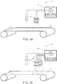
- FIG. 3a shows an embodiment of the invention, in which a machine vision system 30 is disclosed in conjunction with a machine clothing 33 as a moving object.
- the machine vision system 30 comprises an image sensor 31, a lighting device 34 and a data processing device 32 for analysing image data captured by the image sensor 31.
- the image sensor 31 is arranged to capture images from a material web (currently not on the machine clothing 33) in a first operating mode and arranged to capture images from the machine clothing 33 in a second operating mode and to transmit data of each image to the data processing device 32.
- the lighting device 34 is arranged to illuminate the machine clothing 33 (or the material web when available) while imaging so that in both operating modes the illumination type being used is different.
- the lighting device 34 may also be integrated parts of the camera sensor 31.
- the data processing device 32 is configured to analyse the received images captured by the image sensor 31.
- FIG. 3b shows an embodiment of the invention, in which a machine vision system 30 is disclosed in conjunction with a machine clothing 33 as a moving object.
- the machine vision system 30 comprises three image sensors 31a, 31b, 31c, a lighting device 34 and a data processing device 32 for analysing image data captured by the image sensors 31a, 31b, 31c arranged in parallel for imaging the whole width of the machine clothing 33 (and a material web when on the machine clothing 33).
- the image sensors 31a, 31b, 31c are arranged to capture images from the material web in a first operating mode and arranged to capture images from the machine clothing 33 in a second operating mode and to transmit data of each image to the data processing device 32.
- the lighting device 34 is arranged to illuminate the machine clothing 33 (or the material web when available) while imaging so that in both operating modes the illumination type being used is different.
- the lighting device 34 may also be an integrated part of a camera sensor.
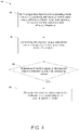
- FIG. 4 shows a monitoring method 40 of a machine vision system according to an example embodiment.
- the machine vision system comprises at least one lighting device, at least one image sensor and a data processing device.
- the machine vision system is monitoring a first object, a material web, in a first operating mode.
- the first object is illuminated by said at least one lighting device using a first type of illumination and images of the first object are captured by said at least one image sensor at a first imaging frequency, and wherein the first object is arranged at least partly on a second object.
- the second object is a machine clothing.
- the captured image data of the captured images is transmitted to the data processing device for analysis.
- the machine vision system changes to monitor the second object in a second operating mode, if absence of the first object on the second object is detected by the data processing device in step 43.
- the second object in the second operating mode is illuminated by said at least one lighting device using a second type of illumination and images of the second object are captured by said at least one image sensor at a second imaging frequency, wherein the first type of illumination is different that the second type of illumination and the second imaging frequency is different than the first imaging frequency.
- the first type of illumination is the same as the second type of illumination or, as an example outside the claimed invention, that the second imaging frequency is the same than the first imaging frequency.
- the various embodiments of the invention are implemented with the help of computer program code that resides in a memory and causes an apparatus to carry out the invention.
- the apparatus that is a computing device, for example, a data processing device may comprise circuitry and electronics for analysing, receiving and transmitting data, a computer program code in a memory, and a processor which, when running the computer program code, causes the apparatus to carry out the features of an embodiment.
- the processor when running the computer program code, is carrying out the steps of the following method: capturing image(s) of a first object by an image sensor, for example, a camera sensor, a first illumination in a first operating mode and capturing image(s) of a second object by the image sensor in a second illumination in a second operating mode, when absence of the first object is detected.
- an image sensor for example, a camera sensor
- the present invention when compared to methods and systems of existing machine vision systems comprising at least an image sensor e.g. a camera suitable for capturing images.
- an image sensor e.g. a camera suitable for capturing images.
- the first mode comprises imaging at a first image capturing frequency at a first illumination
- the second mode comprises imaging at a second image capturing frequency at a second illumination, wherein the change of operating mode from the first mode to the second mode is performed, when it is detected that the first imaging target is unavailable and from the second mode to the first mode is performed, when it is detected that the first imaging target is available again.
Description
- The present invention relates to a method for imaging of continuous manufacturing processes, in which method a camera is used for imaging and a lighting device is used for illuminating a continuous product and fabrics under the continuous product.
- The invention also relates to a system and a computer program product causing a system to carry out the method.
- In continuous manufacturing processes, there are materials or products constantly running through the machine. In such processes, materials and products must be monitored in order to detect possible deviations or web breaks. Furthermore, condition of fabrics under materials or products is checked during scheduled or planned downtimes of a machine/machinery in order to detect possible deviations that may cause those above-mentioned deviations to materials or products or web breaks, but which could also cause unscheduled or planned downtimes of a machine/machinery. The product, machine or process may be monitored, for example, by machine vision systems such as camera systems. The captured images are analysed by a processing unit.
-
JP 2000111483 A - The documents
EP 1 925 725 A1 andUS 5,590,577 disclose systems for detecting tear of a material web being arranged on a machine clothing. - According to a first aspect of the invention, there is provided a method as defined in claim 1.
- According to an embodiment, in the second operating mode said at least one lighting device is reconfigured to use a second type of illumination for illuminating the second object to be monitored. According to the invention, in the second operating mode said at least one camera sensor is reconfigured to capture images at a second image capturing frequency from the second object to be monitored. According to the invention, in the second operating mode image analysing parameters of the data processing device are reconfigured for detecting deviations from the second object to be monitor. According to the invention, the absence of the first object on the second object is detected by the data processing device from captured image data. According to an example outside the claimed invention, the absence is detected from a received external indication signal. According to the invention, the first object is a material web and the second object is a machine clothing. According to an embodiment, the method further comprises: changing the machine vision system for monitoring in the first operating mode, if presence of the first object on the second object is detected in the second operating mode by the data processing device.
- According to a second aspect of the invention, there is provided a machine vision system as defined in claim 4.
- According to an embodiment, in the second operating mode said at least one lighting device is reconfigured to use a second type of illumination for illuminating the second object to be monitored. According to the invention, in the second operating mode said at least one camera sensor is reconfigured to capture images at a second image capturing frequency from the second object to be monitored. According to the invention, in the second operating mode image analysing parameters of the data processing device are reconfigured for detecting deviations from the second object to be monitored. According to the invention, the absence of the first object on the second object is detected by the data processing device from captured image data. According to an example outside the claimed invention said absence may be detected from a received external indication signal.
- According to the invention, the first object is a material web and the second object is a machine clothing. According to an embodiment, the method further comprises: changing the machine vision system for monitoring the first object in the first operating mode, if presence of the first object on the second object is detected in the second operating mode by the data processing device.
- According to a third aspect of the invention, there is provided a computer program as defined in claim 7.
- According to an embodiment, in the second operating mode said at least one lighting device is reconfigured to use a second type of illumination for illuminating the second object to be monitored. According to the invention, in the second operating mode said at least one camera sensor is reconfigured to capture images at a second image capturing frequency from the second object to be monitor. According to the invention, in the second operating mode image analysing parameters of the data processing device are reconfigured for detecting deviations from the second object to be monitored. According to the invention, the absence of the first object on the second object is detected by the data processing device from captured image data. According to an an example outside the claimed invention, the absence is detected from a received external indication signal. According to the invention, the first object is a material web and the second object is a machine clothing. According to an embodiment, the method further comprises: changing the machine vision system for monitoring in the first operating mode, if presence of the first object on the second object is detected in the second operating mode by the data processing device.
- In the following, various embodiments of the invention will be described in more detail with reference to the appended drawings, in which
- Fig. 1a, b
- show a machine vision system according to an example embodiment;
- Fig. 2 a, b
- show a machine vision system according to an example embodiment;
- Fig. 3 a, b
- show a machine vision system according to an example embodiment; and
- Fig. 4
- shows a monitoring method of a machine vision system according to an example embodiment.
- The present invention relates to a machine vision system according to example embodiments having two different operating modes for two different objects and comprising at least one image sensor used for imaging a web product and machine clothing and at least one lighting device for illuminating the web product and the machine clothing. The web product is a first object and it is imaged and illuminated in the first operating mode of the machine vision system. The machine clothing is the second object and it is imaged and illuminated in the second operating mode of the machine vision system.
- The term "web product" refers in this context to any type of a wood fibre web. The term "wood fibre" refers in this context to any suitable wood fibre webs, for example, paper, cellulose or cardboard webs. The term "machine clothing" refers in this context to any type of fabric used, for example, in a paper, cardboard of cellulose machine/machinery for dewatering and/or transporting the web product. It may be, for example, a woven textile belt of felt. The web product and the machine clothing is illuminated and imaged in order to find web deviations from the web product and clothing deviations from the machine clothing. The term "web deviation" includes in this context any deviation detectable from the web product, for example, a defect, a hole, a stain, a definite change, a grey or dark spot, a streak, a wrinkle, an air bubble or a pattern in a web. The term "clothing deviation" includes in this context any deviation detectable from the machine clothing, for example, a defect, a hole, or a risen yarn etc. that may possibly cause machine clothing-related web defect(s). Machine clothing contributes to product quality, fibre and chemical conversion efficiency, and production speed.
- As stated above, a machine vision system according to embodiments of the invention comprises at least one image sensor, at least one lighting device and data processing device. The image sensor is used for capturing images of at least two different kinds of objects, being a web and machine clothing and the lighting device is used for lighting the objects arranged to be imaged. The machine vision system has at least two different operating modes, wherein each mode is arranged to be suitable for a certain target: a first operating mode for the web product and the second operating mode for the machine clothing. Different operating modes may-have different lighting and also the imaging frequency is different. The operating mode may be selected on basis of the imaging target for enabling effective detecting of errors from both objects.
- As discussed, the operating mode being used depends on the object. In the first operating mode the first object, the web product, is illuminated by a first type of illumination and images of the first object is captured at a first imaging frequency and in the second operating mode the second object, the machine clothing, are illuminated by a second type of illumination and images of the first object are continued to be captured at the first imaging frequency but possibly it is changed to the second imaging frequency. When at least one camera of the machine vision system is imaging and at least one lighting device is used for illuminating the web product in the first operating mode and the web product ends, for example, in a case of a web break, a camera sensor of the machine vision system detects the absence of the web or, according to an example outside the claimed invention, an external indication signal about the web break is transmitted to the machine vision system, for example, from a paper machine control system, the first operating mode of the machine vision system used for imaging and illuminating the web product is arranged to be changed to the second operating mode for imaging and illuminating the machine clothing. A second mode reconfiguration signal is at least transmitted to at least one lighting device for reconfiguring the at least one lighting device to the second operating mode. It is also possible that a second mode reconfiguration signal is also transmitted to at least one camera sensor for reconfiguring the at least one camera sensor.
- Respectively, when in the second operating mode the machine vision system detects that the web product is on the machine clothing or an external indication signal indicates to the machine vision system that the web product is on the machine clothing, the second operating mode of the machine vision system is changed to the first operating mode for imaging and lighting the web product until the next web break results in changing to the second operating mode.
- When operating mode changes, also the illumination changes, for example, the type of lights, the number of lights, the direction of lights, the operation of lights or lights being used may change to be more suitable for imaging the object in question. In other words, illumination changes when imaging object changes so that illumination depends on the object to be illuminated. When operating mode changes, the reconfiguration signal may also determine for the image sensor(s) a resolution of images to be captured or how the images should overlap. However, in addition to changing illumination and also imaging frequency, when operating mode changes also image analysing parameters of the data processing device are reconfigured to be more suitable for current object. For example, in the first operating mode image analysing parameters are suitable for detecting deviations in a web product and in the second operating mode image analysing parameters are suitable for detecting deviations in machine clothing. There may be a need for different analysing parameters in different operating modes, because the type of deviations may be different in the web product and in the machine clothing. The colour of the web product and the machine clothing may be different, which may also cause a need for different image analysing parameters.
- An image sensor of the machine vision system may be, for example, a camera, for example, a c-mos or ccd camera, a matrix or line scan camera, a black and white or colour camera, a regular or smart camera, or any suitable camera. Targets arranged to be monitored may be illuminated for imaging by at least one lighting device and a lighting device of the machine vision system may be, for example, a LED or one lighting device may comprise two, three, four or a plurality of LEDs.
- The present invention further relates to a method according to example embodiments of the invention, wherein in a so called first operating mode one or more images of a web product are captured by one or more image sensors when illuminated by one or more lighting device. When the web product ends, for example, in a case of a web brake, or is no more in the process, the machine vision system detects the situation from images captured by one or more image sensor(s) or it receives an external indication signal about the web brake, the machine vision system is changed to the second operating mode for imaging and illuminating the machine clothing. The type of illumination and also the image capturing frequency in the first and second operating mode are different.
- In the second operating mode at least one camera sensor image may capture images and at least one lighting device may illuminate the second type of illumination a predetermined time. In other words, it is possible that they do not continue capturing of images and illuminating until the second operating mode changes to the first operating mode. The machine clothing may comprise a seam or a kind of marking. The imaging and the second type of illumination may be continued at least until the seam or the some kind of marking in the web is detected from the machine clothing at least twice. This way it is ensured that the whole web product is imaged, but unnecessary imaging is avoided. Image data of captured images is analysed by a data processing device of each image sensor of a machine vision system and/or image data of captured images is transmitted to an external data processing device of the machine vision system for analysis. The external data processing device is a data processing device that is not an integrated part of a camera. The data processing device may monitor the data in order to find deviation(s) in image data of a web product and/or monitors image data of machine clothing.
-
Figure 1a shows an embodiment of the invention, in which amachine vision system 10 is disclosed in conjunction with two objects, aweb 17a andmachine clothing 17b. Themachine vision system 10 comprises twolighting devices smart cameras image sensor data processing device Lighting devices movable web 17a and themachine clothing 17b when theweb 17a is not available. Theimage sensors movable web 17a and from themachine clothing 17b when theweb 17a is not available and to transmit image data to thedata processing device smart camera - The
data processing devices image sensor data processing device 13 of thesmart camera 11 and thedata processing device 16 of thesmart camera 14 may be any computing device suitable for handling image data such as a computer. Thedata processing device 13 is in electronic communication with theimage sensor 11 and thelighting device 18 via signal lines and thedata processing device 16 is in electronic communication with theimage sensor 12 and thelighting device 19 via signal lines. Thelighting devices smart cameras smart cameras smart cameras smart cameras - When the
web 17a is on themachine clothing 17b as infigure 1a , theimage sensors web 17a and thelighting devices web 17a in the first operating mode. Thedata processing devices web 17a. Thedata processing devices data processing device 13 detects from the image data that theweb 17a is not on themachine clothing 17b, it reconfigures theimage sensors machine vision system 10 to a second operating mode. Thedata processing devices machine clothing 17b. - As mentioned above, after reconfiguration the
image sensors machine clothing 17b in the second operating mode. In the second operating mode the image capturing frequency is different or, according to an example outside the claimed invention, it may remain the same. The second image capturing frequency of the second operating mode may be, for example, higher than the first image capturing frequency of the first operating mode so that deviations in themachine clothing 17b can be more accurately imaged and detected. Deviations in themachine clothing 17b may be more difficult to detect, so there is a need to capture more images of themachine clothing 17b in order to enable more efficient monitoring of deviations in themachine clothing 17b. In the second operating mode, thelighting devices machine clothing 17b in the second operating mode, wherein the type of illumination of the second operating mode is different than the type of illumination of the first operating mode. There may be a need, for example, for more efficient lighting when imaging themachine clothing 17b in the second operating mode, therefore the intensity of light oflighting devices machine clothing 17b in the second operating mode, therefore the intensity of light oflighting devices machine clothing 17b in the second operating mode at the second image capturing frequency is shown infigure 1b . The need of the intensity of light oflighting devices machine clothing 17b compared to theweb 17a. - In the second operating mode, the
image sensors image sensors data processing devices -
Figure 2a shows an embodiment of the invention, in which amachine vision system 20 is disclosed in conjunction with two objects, aweb 23a andmachine clothing 23b. Themachine vision system 20 comprises at least twoimage sensors lighting devices data processing device 22 for analysing image data captured by the at least twoimage sensors image sensors object 23a that is a material web in a first operating mode and arranged to capture images from the second movingobject 23b that is a machine clothing in a second operating mode and to transmit data of each image to thedata processing device 22. Thelighting devices objects - The
data processing device 22 comprises at least one processor, at least one memory including computer program code for one or more program units, and means for receiving image data wirelessly or via a wired connection, for example, a receiver or a transceiver, and means for transmitting configurations by reconfiguration signals wirelessly or via a wired connection, for example, a transmitter or a transceiver, to thelighting devices image sensors data processing device 22 may be any computing device suitable for handling image data, such as a computer. Thedata processing device 22 is in electronic communication with theimage sensors lighting devices data processing device 22 comprises I/O circuitry. The connection between thelighting devices data processing device 22 and theimage sensors data processing device 22 is a wired or wireless network. Thedata processing device 22 may also include a video controller and an audio controller for generating signals that can be produced to the user with computer accessories. The video controller may be connected to a display. The display may be e.g. a flat panel display or a projector for producing a larger image. The audio controller may be connected to a sound source, such as loudspeakers or earphones. Thedata processing device 22 may also include an acoustic sensor, such as a microphone. Thelighting devices camera sensors - The
data processing device 22 is configured to analyse the received images captured by theimage sensors data processing device 22 detects a deviation or a web break in the first operating mode or presence of a web in the second operating mode, it may indicate it for the process operator and/or transmit reconfiguration signals to at least one lighting device and possibly also to the image sensors. - When the
web 23a is on themachine clothing 23b as infigure 2a , theimage sensors web 23a and thelighting devices web 23a in the first operating mode. Thedata processing device 22 is configured to receive captured image as image data. Thedata processing device 22 is arranged to analyse the image data. If thedata processing device 22 detects from the image data that theweb 23a is not on themachine clothing 23b, it reconfigures theimage sensors lighting devices machine clothing 23b and illuminating theweb machine clothing 23b. Thedata processing device 22 is configured to receive images captured in the second operating mode as image data and analyse the image data in order to find deviations in themachine clothing 23b. - As mentioned above, after reconfiguration to the second operating mode, the
image sensors machine clothing 23b in the second operating mode. In the second operating mode, the image capturing frequency is different or, in an example outside the claimed invention, may remain the same compared to the first operating mode. The second image capturing frequency of the second operating mode may be, for example, higher than the first image capturing frequency of the first operating mode so that deviations in themachine clothing 23b can be more accurately imaged and detected or the second image capturing frequency may be the same in the first and in the second operating mode. Thelighting devices machine clothing 23b in the second operating mode, for example, more efficiently or less efficiently than in the first operating mode depending on the configurations. Imaging of themachine clothing 23b in the second operating mode at the second image capturing frequency is shown infigure 2b . - The
image sensors machine clothing 23b, for example, at least from aseam 28 of themachine clothing 23b toseam 28 i.e. until theseam 28 is detected twice in the images captured by image sensors from theseam 28 by thedata processing device 22. -
Figure 3a shows an embodiment of the invention, in which amachine vision system 30 is disclosed in conjunction with amachine clothing 33 as a moving object. Themachine vision system 30 comprises animage sensor 31, alighting device 34 and adata processing device 32 for analysing image data captured by theimage sensor 31. Theimage sensor 31 is arranged to capture images from a material web (currently not on the machine clothing 33) in a first operating mode and arranged to capture images from themachine clothing 33 in a second operating mode and to transmit data of each image to thedata processing device 32. Thelighting device 34 is arranged to illuminate the machine clothing 33 (or the material web when available) while imaging so that in both operating modes the illumination type being used is different. Thelighting device 34 may also be integrated parts of thecamera sensor 31. Thedata processing device 32 is configured to analyse the received images captured by theimage sensor 31. -
Figure 3b shows an embodiment of the invention, in which amachine vision system 30 is disclosed in conjunction with amachine clothing 33 as a moving object. Themachine vision system 30 comprises threeimage sensors lighting device 34 and adata processing device 32 for analysing image data captured by theimage sensors image sensors machine clothing 33 in a second operating mode and to transmit data of each image to thedata processing device 32. Thelighting device 34 is arranged to illuminate the machine clothing 33 (or the material web when available) while imaging so that in both operating modes the illumination type being used is different. Thelighting device 34 may also be an integrated part of a camera sensor. -
Figure 4 shows amonitoring method 40 of a machine vision system according to an example embodiment. The machine vision system comprises at least one lighting device, at least one image sensor and a data processing device. Instep 41, the machine vision system is monitoring a first object, a material web, in a first operating mode. In a first operating mode the first object is illuminated by said at least one lighting device using a first type of illumination and images of the first object are captured by said at least one image sensor at a first imaging frequency, and wherein the first object is arranged at least partly on a second object. The second object is a machine clothing. Instep 42, the captured image data of the captured images is transmitted to the data processing device for analysis. Instep 44, the machine vision system changes to monitor the second object in a second operating mode, if absence of the first object on the second object is detected by the data processing device instep 43. - In many cases, in the second operating mode the second object is illuminated by said at least one lighting device using a second type of illumination and images of the second object are captured by said at least one image sensor at a second imaging frequency, wherein the first type of illumination is different that the second type of illumination and the second imaging frequency is different than the first imaging frequency. However, in the second operating mode, it may be possible, that the first type of illumination is the same as the second type of illumination or, as an example outside the claimed invention, that the second imaging frequency is the same than the first imaging frequency.
- The various embodiments of the invention are implemented with the help of computer program code that resides in a memory and causes an apparatus to carry out the invention. For example, the apparatus that is a computing device, for example, a data processing device may comprise circuitry and electronics for analysing, receiving and transmitting data, a computer program code in a memory, and a processor which, when running the computer program code, causes the apparatus to carry out the features of an embodiment. The processor, when running the computer program code, is carrying out the steps of the following method: capturing image(s) of a first object by an image sensor, for example, a camera sensor, a first illumination in a first operating mode and capturing image(s) of a second object by the image sensor in a second illumination in a second operating mode, when absence of the first object is detected.
- Considerable advantages are achieved by the present invention when compared to methods and systems of existing machine vision systems comprising at least an image sensor e.g. a camera suitable for capturing images. By means of the arrangement according to the invention it is possible to use the same image sensor for two different objects both needing at least different type of illumination, because the machine vision system has two different operating modes. The first mode comprises imaging at a first image capturing frequency at a first illumination and the second mode comprises imaging at a second image capturing frequency at a second illumination, wherein the change of operating mode from the first mode to the second mode is performed, when it is detected that the first imaging target is unavailable and from the second mode to the first mode is performed, when it is detected that the first imaging target is available again.
- It is obvious that the present invention is not limited solely to the above-presented embodiments, but it can be modified within the scope of the appended claims.
Claims (7)
- A method, comprising:monitoring a material web (17a) in a first operating mode of a machine vision system (10) comprising at least one lighting device (18, 19), at least one image sensor (12, 15) and a data processing device (13, 16),wherein the monitoring in a first operating mode comprises illuminating the material web (17a) by said at least one lighting device (18, 19) using a first type of illumination and capturing images of the material web (17a) by said at least one image sensor (12, 15) at a first image capturing frequency, and wherein the material web (17a) is arranged at least partly on a machine clothing (17b);transmitting the captured image data of the captured images to the data processing device (13, 16) for analysis; andif absence of the material web (17a) on the machine clothing (17b) is detected from the image data captured in the first operating mode by the data processing device (13, 16), the method further comprises:
changing the machine vision system (10) for monitoring the machine clothing (17b) in a second operating mode and for transmitting the captured image data of the captured images to the data processing device (13, 16) for analysis, wherein in the second operating mode said at least one image sensor (12, 15) is reconfigured to capture images at a second image capturing frequency from the machine clothing (17b) to be monitored, and the data processing device (13, 16) is arranged to detect deviations from the image data captured of the machine clothing (17b) with image analyzing parameters reconfigured to be suitable for detecting deviations in the machine clothing (17b) to be monitored, characterized in that in the second operating mode intensity of light of at least one lighting device (18, 19) is increased or decreased for enabling effective detecting of deviations from the machine clothing (17b). - A method according to claim 1, wherein in the second operating mode said at least one lighting device (18, 19) is reconfigured to use a second type of illumination for illuminating the machine clothing (17b) to be monitored.
- A method according to any of the preceding claims, wherein the method further comprises:changing the machine vision system (10) for monitoring in the first operating mode, if presence of the material web (17a) on the machineclothing (17b) is detected in the second operating mode from the image data captured in the second operating mode by the data processing device (13, 16).
- A machine vision system comprising at least one lighting device (18, 19), at least one image sensor (12, 15) and a data processing device (13, 16), and wherein the machine vision system (10) is arranged to monitor a material web object (17a) in a first operating mode and a machine clothing (17b) in a second operating mode, and wherein in the first operating mode at least one lighting device (18, 19) is arranged to illuminate the material web (17a) using a first type of illumination, and said image sensor (12, 15) is arranged to capture images of the material web (17a) at a first image capturing frequency and to transmit said captured image data to the data processing device (13, 16) for analysing, and
wherein the machine vision system (10) is further configured so that
if absence of the material web (17a) on the machine clothing (17b) is detected from the captured image data by the data processing device (13, 16), the machine vision system (10) is changed to the second operating mode for monitoring the machine clothing (17b) in a second operating mode and for transmitting the captured image data of the captured images to the data processing device (13, 16) for analysis, wherein in the second operating mode said at least one image sensor (12, 15) is reconfigured to capture images at a second image capturing frequency from the machine clothing (17b) to be monitored, and the data processing device (13, 16) is arranged to detect deviations from the image data captured of the machine clothing (17b) with image analyzing parameters reconfigured to be suitable for detecting deviations in the machine clothing (17b) to be monitored, characterised in that in the second operating mode intensity of light of at least one lighting device (18, 19) is increased or decreased for enabling effective detecting of deviations from the machine clothing (17b). - A machine vision system according to claim 4, wherein in the second operating mode said at least one lighting device (18, 19) is reconfigured to use a second type of illumination for illuminating the machine clothing (17b) to be monitored.
- A machine vision system according to claim 4 or 5, wherein the machine vision system (10) is configured for changing the machine vision system for monitoring the material web (17a) in the first operating mode, if presence of the material web (17a) on the machine clothing (17b) is detected in the second operating mode by the data processing device (13, 16).
- A computer program product, stored on a computer readable medium and executable in a computing device, wherein the computer program product comprises instructions to cause the system of claim 4 to perform a method according to any of the claims 1 to 3.
Priority Applications (1)
| Application Number | Priority Date | Filing Date | Title |
|---|---|---|---|
| EP22157040.1A EP4019948A1 (en) | 2016-05-06 | 2017-04-28 | A machine vision method and system for monitoring manufacturing processes |
Applications Claiming Priority (2)
| Application Number | Priority Date | Filing Date | Title |
|---|---|---|---|
| FI20165387A FI128850B (en) | 2016-05-06 | 2016-05-06 | A machine vision method and system for monitoring manufacturing processes |
| PCT/FI2017/050325 WO2017191363A1 (en) | 2016-05-06 | 2017-04-28 | A machine vision method and system for monitoring manufacturing processes |
Related Child Applications (2)
| Application Number | Title | Priority Date | Filing Date |
|---|---|---|---|
| EP22157040.1A Division-Into EP4019948A1 (en) | 2016-05-06 | 2017-04-28 | A machine vision method and system for monitoring manufacturing processes |
| EP22157040.1A Division EP4019948A1 (en) | 2016-05-06 | 2017-04-28 | A machine vision method and system for monitoring manufacturing processes |
Publications (3)
| Publication Number | Publication Date |
|---|---|
| EP3452811A1 EP3452811A1 (en) | 2019-03-13 |
| EP3452811A4 EP3452811A4 (en) | 2020-01-22 |
| EP3452811B1 true EP3452811B1 (en) | 2022-05-25 |
Family
ID=60202816
Family Applications (2)
| Application Number | Title | Priority Date | Filing Date |
|---|---|---|---|
| EP22157040.1A Pending EP4019948A1 (en) | 2016-05-06 | 2017-04-28 | A machine vision method and system for monitoring manufacturing processes |
| EP17792559.1A Active EP3452811B1 (en) | 2016-05-06 | 2017-04-28 | A machine vision method and system for monitoring manufacturing processes |
Family Applications Before (1)
| Application Number | Title | Priority Date | Filing Date |
|---|---|---|---|
| EP22157040.1A Pending EP4019948A1 (en) | 2016-05-06 | 2017-04-28 | A machine vision method and system for monitoring manufacturing processes |
Country Status (8)
| Country | Link |
|---|---|
| US (1) | US10884401B2 (en) |
| EP (2) | EP4019948A1 (en) |
| JP (1) | JP7090032B2 (en) |
| CN (1) | CN109416327B (en) |
| ES (1) | ES2923908T3 (en) |
| FI (1) | FI128850B (en) |
| PL (1) | PL3452811T3 (en) |
| WO (1) | WO2017191363A1 (en) |
Families Citing this family (8)
| Publication number | Priority date | Publication date | Assignee | Title |
|---|---|---|---|---|
| CN112189133B (en) * | 2018-05-31 | 2023-04-18 | 株式会社Psm国际 | Method and apparatus for measuring quality of long sheet |
| FI128235B (en) | 2018-12-10 | 2020-01-15 | Procemex Oy Ltd | Overhead sidelight |
| JP7269126B2 (en) * | 2019-07-31 | 2023-05-08 | ファナック株式会社 | Imaging detection data transmission system |
| CN111650208B (en) * | 2020-06-01 | 2021-08-27 | 东华大学 | Tour type woven fabric defect on-line detector |
| US20230213458A1 (en) * | 2021-12-30 | 2023-07-06 | CreateMe Technologies LLC | Automated inspection measurement in garment manufacturing |
| CN115201201B (en) * | 2022-06-24 | 2023-08-01 | 广东工业大学 | Forming mesh quality detection method based on machine vision |
| US11932991B2 (en) * | 2022-08-03 | 2024-03-19 | Industrial Video Solutions Inc. | Systems and methods for monitoring and controlling industrial processes |
| US11816893B1 (en) | 2022-08-03 | 2023-11-14 | Industrial Video Solutions Inc. | Systems and methods for monitoring and controlling industrial processes |
Family Cites Families (30)
| Publication number | Priority date | Publication date | Assignee | Title |
|---|---|---|---|---|
| US4845374A (en) | 1987-07-20 | 1989-07-04 | R. J. Reynolds Tobacco Company | Method and apparatus for detecting the deposition of an adhesive on a travelling web |
| DE4216653C2 (en) * | 1992-05-20 | 1995-12-21 | Voith Gmbh J M | Tear monitoring device for paper webs |
| US5314072A (en) | 1992-09-02 | 1994-05-24 | Rutgers, The State University | Sorting plastic bottles for recycling |
| US5815198A (en) * | 1996-05-31 | 1998-09-29 | Vachtsevanos; George J. | Method and apparatus for analyzing an image to detect and identify defects |
| JP2000111483A (en) * | 1998-10-02 | 2000-04-21 | Dainippon Printing Co Ltd | Method and apparatus for inspection of cyclic pattern |
| JP2000111493A (en) | 1998-10-03 | 2000-04-21 | Kenji Shibahara | Inspection method for surface state |
| US6158576A (en) | 1998-10-15 | 2000-12-12 | Albany International Corp. | Endless belt or fabric for use in process control loop |
| US6750466B2 (en) | 2001-02-09 | 2004-06-15 | Wintriss Engineering Corporation | Web inspection system |
| FI115588B (en) * | 2001-11-02 | 2005-05-31 | Metso Automation Oy | Camera Interface |
| FI115163B (en) | 2001-11-29 | 2005-03-15 | Metso Automation Oy | Quality and condition control according to spectrum discriminant measurement |
| FI20025055A0 (en) * | 2002-03-27 | 2002-12-03 | Metso Paper Inc | Method for controlling a paper or board machine |
| DE10249385A1 (en) | 2002-10-23 | 2004-05-06 | Voith Paper Patent Gmbh | Method and device for monitoring the condition of a covering |
| JP2004226328A (en) | 2003-01-24 | 2004-08-12 | Hitachi Ltd | Appearance inspection system, quality evaluation system using the same and quality evaluation information providing system |
| DE10343517A1 (en) | 2003-09-19 | 2005-05-04 | Voith Paper Patent Gmbh | Method and arrangement for determining the water permeability of a fabric |
| FI118775B (en) | 2005-05-12 | 2008-03-14 | Metso Paper Inc | Method and apparatus for checking the condition of a shoe roller |
| FI119708B (en) * | 2006-02-01 | 2009-02-13 | Viconsys Oy | Device for checking a path |
| US20090060316A1 (en) | 2006-02-22 | 2009-03-05 | Hannu Ruuska | Method for Monitoring a Rapidly-Moving Paper Web and Corresponding System |
| DE102006055823A1 (en) | 2006-11-27 | 2008-05-29 | Voith Patent Gmbh | Method for detecting a tear of a fibrous web in a dryer section of a machine for producing the fibrous web and drying wire for carrying out the method |
| WO2008107892A1 (en) | 2007-03-06 | 2008-09-12 | Advanced Vision Technology (Avt) Ltd. | System and method for detecting the contour of an object on a moving conveyor belt |
| US20090028417A1 (en) | 2007-07-26 | 2009-01-29 | 3M Innovative Properties Company | Fiducial marking for multi-unit process spatial synchronization |
| DE102007045895A1 (en) * | 2007-09-26 | 2009-04-09 | Voith Patent Gmbh | A band calendering apparatus and method of operating a band calendering apparatus |
| US7986410B2 (en) * | 2008-03-18 | 2011-07-26 | Voith Patent Gmbh | Method for detecting a fibrous web tear in a drying section of a machine for producing the fibrous web and apparatus for performing said method |
| FI20106053A0 (en) * | 2010-10-13 | 2010-10-13 | Metso Automation Oy | Track monitoring system and corresponding track monitoring method |
| DE102011078010A1 (en) * | 2011-06-22 | 2012-12-27 | Voith Patent Gmbh | Method for monitoring homogeneous properties of cover for transportation of paper web through dry end of paper machine, involves determining degree of contamination by judging contrast between clean and contaminated surface portions |
| US8591703B2 (en) | 2011-07-06 | 2013-11-26 | Voith Patent Gmbh | Monofilament yarn for a paper machine clothing fabric |
| CN202221415U (en) | 2011-09-03 | 2012-05-16 | 山东轻工业学院 | Surface defect online detection system for wide breadth paper |
| DE102011113670A1 (en) * | 2011-09-20 | 2013-03-21 | Schott Ag | Lighting device, inspection device and inspection method for the optical inspection of an object |
| FI125725B (en) * | 2011-11-15 | 2016-01-29 | Valmet Technologies Oy | Method and apparatus for following a fiber web |
| DE102012208201A1 (en) * | 2012-05-16 | 2013-11-21 | Voith Patent Gmbh | Method for detecting contamination of a paper machine clothing |
| FI128403B (en) | 2013-07-05 | 2020-04-30 | Procemex Oy Ltd | Synchronization of imaging |
-
2016
- 2016-05-06 FI FI20165387A patent/FI128850B/en active IP Right Grant
-
2017
- 2017-04-28 PL PL17792559.1T patent/PL3452811T3/en unknown
- 2017-04-28 WO PCT/FI2017/050325 patent/WO2017191363A1/en active Search and Examination
- 2017-04-28 EP EP22157040.1A patent/EP4019948A1/en active Pending
- 2017-04-28 EP EP17792559.1A patent/EP3452811B1/en active Active
- 2017-04-28 ES ES17792559T patent/ES2923908T3/en active Active
- 2017-04-28 JP JP2018558234A patent/JP7090032B2/en active Active
- 2017-04-28 US US16/095,790 patent/US10884401B2/en active Active
- 2017-04-28 CN CN201780028058.9A patent/CN109416327B/en active Active
Also Published As
| Publication number | Publication date |
|---|---|
| JP2019518943A (en) | 2019-07-04 |
| US10884401B2 (en) | 2021-01-05 |
| EP3452811A4 (en) | 2020-01-22 |
| JP7090032B2 (en) | 2022-06-23 |
| FI128850B (en) | 2021-01-29 |
| CN109416327B (en) | 2021-10-26 |
| WO2017191363A1 (en) | 2017-11-09 |
| EP3452811A1 (en) | 2019-03-13 |
| CN109416327A (en) | 2019-03-01 |
| ES2923908T3 (en) | 2022-10-03 |
| US20190129396A1 (en) | 2019-05-02 |
| PL3452811T3 (en) | 2022-10-10 |
| FI20165387A (en) | 2017-11-07 |
| EP4019948A1 (en) | 2022-06-29 |
Similar Documents
| Publication | Publication Date | Title |
|---|---|---|
| EP3452811B1 (en) | A machine vision method and system for monitoring manufacturing processes | |
| CN112748120B (en) | Defect detection system, defect detection method, defect detection device, defect detection equipment and storage medium | |
| EP3452806B1 (en) | A machine vision method and system | |
| JP5195004B2 (en) | Running yarn inspection method and carbon fiber manufacturing method using the same | |
| US20120078576A1 (en) | Monitoring System and Apparatus Comprising Such a Monitoring System | |
| JP2019518943A5 (en) | ||
| US9532015B2 (en) | Synchronization of imaging | |
| WO2012139088A2 (en) | System and method for generating multiple, interlaced images using a single scanning camera with multiple, alternating light sources | |
| KR20000035510A (en) | Monitoring apparatus | |
| FI128820B (en) | A machine vision method and system for monitoring manufacturing processes | |
| US20210348334A1 (en) | Monitoring system | |
| JP2008128822A (en) | Device and method for inspecting appearance of sheet material having translucency | |
| JP2021128110A (en) | Belt conveyor monitoring device | |
| US11128808B2 (en) | Overhead sidelight | |
| JP5600996B2 (en) | Paper cup inspection apparatus and method | |
| IT202100017105A1 (en) | Process and inspection system of a continuous sliding belt |
Legal Events
| Date | Code | Title | Description |
|---|---|---|---|
| STAA | Information on the status of an ep patent application or granted ep patent |
Free format text: STATUS: THE INTERNATIONAL PUBLICATION HAS BEEN MADE |
|
| PUAI | Public reference made under article 153(3) epc to a published international application that has entered the european phase |
Free format text: ORIGINAL CODE: 0009012 |
|
| STAA | Information on the status of an ep patent application or granted ep patent |
Free format text: STATUS: REQUEST FOR EXAMINATION WAS MADE |
|
| 17P | Request for examination filed |
Effective date: 20181025 |
|
| AK | Designated contracting states |
Kind code of ref document: A1 Designated state(s): AL AT BE BG CH CY CZ DE DK EE ES FI FR GB GR HR HU IE IS IT LI LT LU LV MC MK MT NL NO PL PT RO RS SE SI SK SM TR |
|
| AX | Request for extension of the european patent |
Extension state: BA ME |
|
| STAA | Information on the status of an ep patent application or granted ep patent |
Free format text: STATUS: REQUEST FOR EXAMINATION WAS MADE |
|
| DAV | Request for validation of the european patent (deleted) | ||
| DAX | Request for extension of the european patent (deleted) | ||
| A4 | Supplementary search report drawn up and despatched |
Effective date: 20200107 |
|
| RIC1 | Information provided on ipc code assigned before grant |
Ipc: D21F 7/04 20060101ALI20191219BHEP Ipc: D21G 9/00 20060101ALI20191219BHEP Ipc: G01N 21/898 20060101ALI20191219BHEP Ipc: B65G 47/00 20060101ALI20191219BHEP Ipc: G05B 13/02 20060101ALI20191219BHEP Ipc: D21F 7/08 20060101ALI20191219BHEP Ipc: G01N 21/01 20060101ALI20191219BHEP Ipc: G01N 21/17 20060101ALI20191219BHEP Ipc: D21F 1/10 20060101ALI20191219BHEP Ipc: G01N 21/89 20060101AFI20191219BHEP Ipc: G05B 19/418 20060101ALI20191219BHEP Ipc: G01N 21/84 20060101ALI20191219BHEP Ipc: G01N 21/88 20060101ALI20191219BHEP Ipc: D21F 1/00 20060101ALI20191219BHEP Ipc: G06T 7/00 20170101ALI20191219BHEP |
|
| GRAP | Despatch of communication of intention to grant a patent |
Free format text: ORIGINAL CODE: EPIDOSNIGR1 |
|
| STAA | Information on the status of an ep patent application or granted ep patent |
Free format text: STATUS: GRANT OF PATENT IS INTENDED |
|
| INTG | Intention to grant announced |
Effective date: 20211220 |
|
| GRAS | Grant fee paid |
Free format text: ORIGINAL CODE: EPIDOSNIGR3 |
|
| GRAA | (expected) grant |
Free format text: ORIGINAL CODE: 0009210 |
|
| STAA | Information on the status of an ep patent application or granted ep patent |
Free format text: STATUS: THE PATENT HAS BEEN GRANTED |
|
| AK | Designated contracting states |
Kind code of ref document: B1 Designated state(s): AL AT BE BG CH CY CZ DE DK EE ES FI FR GB GR HR HU IE IS IT LI LT LU LV MC MK MT NL NO PL PT RO RS SE SI SK SM TR |
|
| REG | Reference to a national code |
Ref country code: GB Ref legal event code: FG4D |
|
| REG | Reference to a national code |
Ref country code: CH Ref legal event code: EP |
|
| REG | Reference to a national code |
Ref country code: DE Ref legal event code: R096 Ref document number: 602017057848 Country of ref document: DE |
|
| REG | Reference to a national code |
Ref country code: AT Ref legal event code: REF Ref document number: 1494453 Country of ref document: AT Kind code of ref document: T Effective date: 20220615 |
|
| REG | Reference to a national code |
Ref country code: IE Ref legal event code: FG4D |
|
| REG | Reference to a national code |
Ref country code: SE Ref legal event code: TRGR |
|
| REG | Reference to a national code |
Ref country code: LT Ref legal event code: MG9D |
|
| REG | Reference to a national code |
Ref country code: NL Ref legal event code: MP Effective date: 20220525 |
|
| REG | Reference to a national code |
Ref country code: ES Ref legal event code: FG2A Ref document number: 2923908 Country of ref document: ES Kind code of ref document: T3 Effective date: 20221003 |
|
| PG25 | Lapsed in a contracting state [announced via postgrant information from national office to epo] |
Ref country code: PT Free format text: LAPSE BECAUSE OF FAILURE TO SUBMIT A TRANSLATION OF THE DESCRIPTION OR TO PAY THE FEE WITHIN THE PRESCRIBED TIME-LIMIT Effective date: 20220926 Ref country code: NO Free format text: LAPSE BECAUSE OF FAILURE TO SUBMIT A TRANSLATION OF THE DESCRIPTION OR TO PAY THE FEE WITHIN THE PRESCRIBED TIME-LIMIT Effective date: 20220825 Ref country code: NL Free format text: LAPSE BECAUSE OF FAILURE TO SUBMIT A TRANSLATION OF THE DESCRIPTION OR TO PAY THE FEE WITHIN THE PRESCRIBED TIME-LIMIT Effective date: 20220525 Ref country code: LT Free format text: LAPSE BECAUSE OF FAILURE TO SUBMIT A TRANSLATION OF THE DESCRIPTION OR TO PAY THE FEE WITHIN THE PRESCRIBED TIME-LIMIT Effective date: 20220525 Ref country code: HR Free format text: LAPSE BECAUSE OF FAILURE TO SUBMIT A TRANSLATION OF THE DESCRIPTION OR TO PAY THE FEE WITHIN THE PRESCRIBED TIME-LIMIT Effective date: 20220525 Ref country code: GR Free format text: LAPSE BECAUSE OF FAILURE TO SUBMIT A TRANSLATION OF THE DESCRIPTION OR TO PAY THE FEE WITHIN THE PRESCRIBED TIME-LIMIT Effective date: 20220826 Ref country code: FI Free format text: LAPSE BECAUSE OF FAILURE TO SUBMIT A TRANSLATION OF THE DESCRIPTION OR TO PAY THE FEE WITHIN THE PRESCRIBED TIME-LIMIT Effective date: 20220525 Ref country code: BG Free format text: LAPSE BECAUSE OF FAILURE TO SUBMIT A TRANSLATION OF THE DESCRIPTION OR TO PAY THE FEE WITHIN THE PRESCRIBED TIME-LIMIT Effective date: 20220825 |
|
| PG25 | Lapsed in a contracting state [announced via postgrant information from national office to epo] |
Ref country code: RS Free format text: LAPSE BECAUSE OF FAILURE TO SUBMIT A TRANSLATION OF THE DESCRIPTION OR TO PAY THE FEE WITHIN THE PRESCRIBED TIME-LIMIT Effective date: 20220525 Ref country code: LV Free format text: LAPSE BECAUSE OF FAILURE TO SUBMIT A TRANSLATION OF THE DESCRIPTION OR TO PAY THE FEE WITHIN THE PRESCRIBED TIME-LIMIT Effective date: 20220525 Ref country code: IS Free format text: LAPSE BECAUSE OF FAILURE TO SUBMIT A TRANSLATION OF THE DESCRIPTION OR TO PAY THE FEE WITHIN THE PRESCRIBED TIME-LIMIT Effective date: 20220925 |
|
| PG25 | Lapsed in a contracting state [announced via postgrant information from national office to epo] |
Ref country code: SM Free format text: LAPSE BECAUSE OF FAILURE TO SUBMIT A TRANSLATION OF THE DESCRIPTION OR TO PAY THE FEE WITHIN THE PRESCRIBED TIME-LIMIT Effective date: 20220525 Ref country code: SK Free format text: LAPSE BECAUSE OF FAILURE TO SUBMIT A TRANSLATION OF THE DESCRIPTION OR TO PAY THE FEE WITHIN THE PRESCRIBED TIME-LIMIT Effective date: 20220525 Ref country code: RO Free format text: LAPSE BECAUSE OF FAILURE TO SUBMIT A TRANSLATION OF THE DESCRIPTION OR TO PAY THE FEE WITHIN THE PRESCRIBED TIME-LIMIT Effective date: 20220525 Ref country code: EE Free format text: LAPSE BECAUSE OF FAILURE TO SUBMIT A TRANSLATION OF THE DESCRIPTION OR TO PAY THE FEE WITHIN THE PRESCRIBED TIME-LIMIT Effective date: 20220525 Ref country code: DK Free format text: LAPSE BECAUSE OF FAILURE TO SUBMIT A TRANSLATION OF THE DESCRIPTION OR TO PAY THE FEE WITHIN THE PRESCRIBED TIME-LIMIT Effective date: 20220525 Ref country code: CZ Free format text: LAPSE BECAUSE OF FAILURE TO SUBMIT A TRANSLATION OF THE DESCRIPTION OR TO PAY THE FEE WITHIN THE PRESCRIBED TIME-LIMIT Effective date: 20220525 |
|
| REG | Reference to a national code |
Ref country code: DE Ref legal event code: R097 Ref document number: 602017057848 Country of ref document: DE |
|
| PG25 | Lapsed in a contracting state [announced via postgrant information from national office to epo] |
Ref country code: AL Free format text: LAPSE BECAUSE OF FAILURE TO SUBMIT A TRANSLATION OF THE DESCRIPTION OR TO PAY THE FEE WITHIN THE PRESCRIBED TIME-LIMIT Effective date: 20220525 |
|
| PLBE | No opposition filed within time limit |
Free format text: ORIGINAL CODE: 0009261 |
|
| STAA | Information on the status of an ep patent application or granted ep patent |
Free format text: STATUS: NO OPPOSITION FILED WITHIN TIME LIMIT |
|
| 26N | No opposition filed |
Effective date: 20230228 |
|
| PG25 | Lapsed in a contracting state [announced via postgrant information from national office to epo] |
Ref country code: SI Free format text: LAPSE BECAUSE OF FAILURE TO SUBMIT A TRANSLATION OF THE DESCRIPTION OR TO PAY THE FEE WITHIN THE PRESCRIBED TIME-LIMIT Effective date: 20220525 |
|
| REG | Reference to a national code |
Ref country code: AT Ref legal event code: UEP Ref document number: 1494453 Country of ref document: AT Kind code of ref document: T Effective date: 20220525 |
|
| P01 | Opt-out of the competence of the unified patent court (upc) registered |
Effective date: 20230620 |
|
| PGFP | Annual fee paid to national office [announced via postgrant information from national office to epo] |
Ref country code: IT Payment date: 20230418 Year of fee payment: 7 Ref country code: FR Payment date: 20230412 Year of fee payment: 7 Ref country code: ES Payment date: 20230531 Year of fee payment: 7 Ref country code: DE Payment date: 20230419 Year of fee payment: 7 |
|
| PGFP | Annual fee paid to national office [announced via postgrant information from national office to epo] |
Ref country code: SE Payment date: 20230417 Year of fee payment: 7 Ref country code: PL Payment date: 20230414 Year of fee payment: 7 Ref country code: AT Payment date: 20230419 Year of fee payment: 7 |
|
| PGFP | Annual fee paid to national office [announced via postgrant information from national office to epo] |
Ref country code: GB Payment date: 20230417 Year of fee payment: 7 |
|
| REG | Reference to a national code |
Ref country code: CH Ref legal event code: PL |
|
| PG25 | Lapsed in a contracting state [announced via postgrant information from national office to epo] |
Ref country code: LU Free format text: LAPSE BECAUSE OF NON-PAYMENT OF DUE FEES Effective date: 20230428 |
|
| REG | Reference to a national code |
Ref country code: BE Ref legal event code: MM Effective date: 20230430 |
|
| PG25 | Lapsed in a contracting state [announced via postgrant information from national office to epo] |
Ref country code: MC Free format text: LAPSE BECAUSE OF FAILURE TO SUBMIT A TRANSLATION OF THE DESCRIPTION OR TO PAY THE FEE WITHIN THE PRESCRIBED TIME-LIMIT Effective date: 20220525 |
|
| PG25 | Lapsed in a contracting state [announced via postgrant information from national office to epo] |
Ref country code: MC Free format text: LAPSE BECAUSE OF FAILURE TO SUBMIT A TRANSLATION OF THE DESCRIPTION OR TO PAY THE FEE WITHIN THE PRESCRIBED TIME-LIMIT Effective date: 20220525 Ref country code: LI Free format text: LAPSE BECAUSE OF NON-PAYMENT OF DUE FEES Effective date: 20230430 Ref country code: CH Free format text: LAPSE BECAUSE OF NON-PAYMENT OF DUE FEES Effective date: 20230430 |
|
| REG | Reference to a national code |
Ref country code: IE Ref legal event code: MM4A |
|
| PG25 | Lapsed in a contracting state [announced via postgrant information from national office to epo] |
Ref country code: BE Free format text: LAPSE BECAUSE OF NON-PAYMENT OF DUE FEES Effective date: 20230430 |