JP7090032B2 - Machine vision methods and systems for monitoring manufacturing processes - Google Patents
Machine vision methods and systems for monitoring manufacturing processes Download PDFInfo
- Publication number
- JP7090032B2 JP7090032B2 JP2018558234A JP2018558234A JP7090032B2 JP 7090032 B2 JP7090032 B2 JP 7090032B2 JP 2018558234 A JP2018558234 A JP 2018558234A JP 2018558234 A JP2018558234 A JP 2018558234A JP 7090032 B2 JP7090032 B2 JP 7090032B2
- Authority
- JP
- Japan
- Prior art keywords
- image
- mode
- data processing
- machine vision
- vision system
- Prior art date
- Legal status (The legal status is an assumption and is not a legal conclusion. Google has not performed a legal analysis and makes no representation as to the accuracy of the status listed.)
- Active
Links
Images


Classifications
-
- G—PHYSICS
- G05—CONTROLLING; REGULATING
- G05B—CONTROL OR REGULATING SYSTEMS IN GENERAL; FUNCTIONAL ELEMENTS OF SUCH SYSTEMS; MONITORING OR TESTING ARRANGEMENTS FOR SUCH SYSTEMS OR ELEMENTS
- G05B19/00—Programme-control systems
- G05B19/02—Programme-control systems electric
- G05B19/418—Total factory control, i.e. centrally controlling a plurality of machines, e.g. direct or distributed numerical control [DNC], flexible manufacturing systems [FMS], integrated manufacturing systems [IMS], computer integrated manufacturing [CIM]
- G05B19/41875—Total factory control, i.e. centrally controlling a plurality of machines, e.g. direct or distributed numerical control [DNC], flexible manufacturing systems [FMS], integrated manufacturing systems [IMS], computer integrated manufacturing [CIM] characterised by quality surveillance of production
-
- D—TEXTILES; PAPER
- D21—PAPER-MAKING; PRODUCTION OF CELLULOSE
- D21F—PAPER-MAKING MACHINES; METHODS OF PRODUCING PAPER THEREON
- D21F1/00—Wet end of machines for making continuous webs of paper
- D21F1/0027—Screen-cloths
-
- G—PHYSICS
- G01—MEASURING; TESTING
- G01N—INVESTIGATING OR ANALYSING MATERIALS BY DETERMINING THEIR CHEMICAL OR PHYSICAL PROPERTIES
- G01N21/00—Investigating or analysing materials by the use of optical means, i.e. using sub-millimetre waves, infrared, visible or ultraviolet light
- G01N21/17—Systems in which incident light is modified in accordance with the properties of the material investigated
- G01N21/25—Colour; Spectral properties, i.e. comparison of effect of material on the light at two or more different wavelengths or wavelength bands
-
- D—TEXTILES; PAPER
- D21—PAPER-MAKING; PRODUCTION OF CELLULOSE
- D21F—PAPER-MAKING MACHINES; METHODS OF PRODUCING PAPER THEREON
- D21F7/00—Other details of machines for making continuous webs of paper
- D21F7/04—Paper-break control devices
-
- D—TEXTILES; PAPER
- D21—PAPER-MAKING; PRODUCTION OF CELLULOSE
- D21G—CALENDERS; ACCESSORIES FOR PAPER-MAKING MACHINES
- D21G9/00—Other accessories for paper-making machines
- D21G9/0009—Paper-making control systems
-
- G—PHYSICS
- G01—MEASURING; TESTING
- G01N—INVESTIGATING OR ANALYSING MATERIALS BY DETERMINING THEIR CHEMICAL OR PHYSICAL PROPERTIES
- G01N21/00—Investigating or analysing materials by the use of optical means, i.e. using sub-millimetre waves, infrared, visible or ultraviolet light
- G01N21/17—Systems in which incident light is modified in accordance with the properties of the material investigated
-
- G—PHYSICS
- G01—MEASURING; TESTING
- G01N—INVESTIGATING OR ANALYSING MATERIALS BY DETERMINING THEIR CHEMICAL OR PHYSICAL PROPERTIES
- G01N21/00—Investigating or analysing materials by the use of optical means, i.e. using sub-millimetre waves, infrared, visible or ultraviolet light
- G01N21/84—Systems specially adapted for particular applications
- G01N21/88—Investigating the presence of flaws or contamination
- G01N21/89—Investigating the presence of flaws or contamination in moving material, e.g. running paper or textiles
- G01N21/8901—Optical details; Scanning details
-
- G—PHYSICS
- G01—MEASURING; TESTING
- G01N—INVESTIGATING OR ANALYSING MATERIALS BY DETERMINING THEIR CHEMICAL OR PHYSICAL PROPERTIES
- G01N21/00—Investigating or analysing materials by the use of optical means, i.e. using sub-millimetre waves, infrared, visible or ultraviolet light
- G01N21/84—Systems specially adapted for particular applications
- G01N21/88—Investigating the presence of flaws or contamination
- G01N21/89—Investigating the presence of flaws or contamination in moving material, e.g. running paper or textiles
- G01N21/892—Investigating the presence of flaws or contamination in moving material, e.g. running paper or textiles characterised by the flaw, defect or object feature examined
- G01N21/898—Irregularities in textured or patterned surfaces, e.g. textiles, wood
- G01N21/8983—Irregularities in textured or patterned surfaces, e.g. textiles, wood for testing textile webs, i.e. woven material
-
- G—PHYSICS
- G05—CONTROLLING; REGULATING
- G05B—CONTROL OR REGULATING SYSTEMS IN GENERAL; FUNCTIONAL ELEMENTS OF SUCH SYSTEMS; MONITORING OR TESTING ARRANGEMENTS FOR SUCH SYSTEMS OR ELEMENTS
- G05B13/00—Adaptive control systems, i.e. systems automatically adjusting themselves to have a performance which is optimum according to some preassigned criterion
- G05B13/02—Adaptive control systems, i.e. systems automatically adjusting themselves to have a performance which is optimum according to some preassigned criterion electric
-
- G—PHYSICS
- G05—CONTROLLING; REGULATING
- G05B—CONTROL OR REGULATING SYSTEMS IN GENERAL; FUNCTIONAL ELEMENTS OF SUCH SYSTEMS; MONITORING OR TESTING ARRANGEMENTS FOR SUCH SYSTEMS OR ELEMENTS
- G05B19/00—Programme-control systems
- G05B19/02—Programme-control systems electric
- G05B19/418—Total factory control, i.e. centrally controlling a plurality of machines, e.g. direct or distributed numerical control [DNC], flexible manufacturing systems [FMS], integrated manufacturing systems [IMS], computer integrated manufacturing [CIM]
- G05B19/4184—Total factory control, i.e. centrally controlling a plurality of machines, e.g. direct or distributed numerical control [DNC], flexible manufacturing systems [FMS], integrated manufacturing systems [IMS], computer integrated manufacturing [CIM] characterised by fault tolerance, reliability of production system
-
- G—PHYSICS
- G05—CONTROLLING; REGULATING
- G05B—CONTROL OR REGULATING SYSTEMS IN GENERAL; FUNCTIONAL ELEMENTS OF SUCH SYSTEMS; MONITORING OR TESTING ARRANGEMENTS FOR SUCH SYSTEMS OR ELEMENTS
- G05B23/00—Testing or monitoring of control systems or parts thereof
- G05B23/02—Electric testing or monitoring
- G05B23/0205—Electric testing or monitoring by means of a monitoring system capable of detecting and responding to faults
- G05B23/0259—Electric testing or monitoring by means of a monitoring system capable of detecting and responding to faults characterized by the response to fault detection
- G05B23/0297—Reconfiguration of monitoring system, e.g. use of virtual sensors; change monitoring method as a response to monitoring results
-
- G—PHYSICS
- G01—MEASURING; TESTING
- G01N—INVESTIGATING OR ANALYSING MATERIALS BY DETERMINING THEIR CHEMICAL OR PHYSICAL PROPERTIES
- G01N21/00—Investigating or analysing materials by the use of optical means, i.e. using sub-millimetre waves, infrared, visible or ultraviolet light
- G01N21/84—Systems specially adapted for particular applications
- G01N21/88—Investigating the presence of flaws or contamination
- G01N21/8851—Scan or image signal processing specially adapted therefor, e.g. for scan signal adjustment, for detecting different kinds of defects, for compensating for structures, markings, edges
- G01N2021/8854—Grading and classifying of flaws
- G01N2021/8867—Grading and classifying of flaws using sequentially two or more inspection runs, e.g. coarse and fine, or detecting then analysing
-
- G—PHYSICS
- G01—MEASURING; TESTING
- G01N—INVESTIGATING OR ANALYSING MATERIALS BY DETERMINING THEIR CHEMICAL OR PHYSICAL PROPERTIES
- G01N21/00—Investigating or analysing materials by the use of optical means, i.e. using sub-millimetre waves, infrared, visible or ultraviolet light
- G01N21/84—Systems specially adapted for particular applications
- G01N21/88—Investigating the presence of flaws or contamination
- G01N21/89—Investigating the presence of flaws or contamination in moving material, e.g. running paper or textiles
- G01N21/8901—Optical details; Scanning details
- G01N21/8903—Optical details; Scanning details using a multiple detector array
-
- G—PHYSICS
- G05—CONTROLLING; REGULATING
- G05B—CONTROL OR REGULATING SYSTEMS IN GENERAL; FUNCTIONAL ELEMENTS OF SUCH SYSTEMS; MONITORING OR TESTING ARRANGEMENTS FOR SUCH SYSTEMS OR ELEMENTS
- G05B2219/00—Program-control systems
- G05B2219/30—Nc systems
- G05B2219/31—From computer integrated manufacturing till monitoring
- G05B2219/31446—Detect if workpiece, object present
-
- G—PHYSICS
- G05—CONTROLLING; REGULATING
- G05B—CONTROL OR REGULATING SYSTEMS IN GENERAL; FUNCTIONAL ELEMENTS OF SUCH SYSTEMS; MONITORING OR TESTING ARRANGEMENTS FOR SUCH SYSTEMS OR ELEMENTS
- G05B2219/00—Program-control systems
- G05B2219/30—Nc systems
- G05B2219/31—From computer integrated manufacturing till monitoring
- G05B2219/31455—Monitor process status
-
- G—PHYSICS
- G05—CONTROLLING; REGULATING
- G05B—CONTROL OR REGULATING SYSTEMS IN GENERAL; FUNCTIONAL ELEMENTS OF SUCH SYSTEMS; MONITORING OR TESTING ARRANGEMENTS FOR SUCH SYSTEMS OR ELEMENTS
- G05B2219/00—Program-control systems
- G05B2219/30—Nc systems
- G05B2219/37—Measurements
- G05B2219/37555—Camera detects orientation, position workpiece, points of workpiece
-
- G—PHYSICS
- G05—CONTROLLING; REGULATING
- G05B—CONTROL OR REGULATING SYSTEMS IN GENERAL; FUNCTIONAL ELEMENTS OF SUCH SYSTEMS; MONITORING OR TESTING ARRANGEMENTS FOR SUCH SYSTEMS OR ELEMENTS
- G05B2219/00—Program-control systems
- G05B2219/30—Nc systems
- G05B2219/37—Measurements
- G05B2219/37572—Camera, tv, vision
-
- G—PHYSICS
- G05—CONTROLLING; REGULATING
- G05B—CONTROL OR REGULATING SYSTEMS IN GENERAL; FUNCTIONAL ELEMENTS OF SUCH SYSTEMS; MONITORING OR TESTING ARRANGEMENTS FOR SUCH SYSTEMS OR ELEMENTS
- G05B2219/00—Program-control systems
- G05B2219/30—Nc systems
- G05B2219/45—Nc applications
- G05B2219/45196—Textile, embroidery, stitching machine
-
- G—PHYSICS
- G05—CONTROLLING; REGULATING
- G05B—CONTROL OR REGULATING SYSTEMS IN GENERAL; FUNCTIONAL ELEMENTS OF SUCH SYSTEMS; MONITORING OR TESTING ARRANGEMENTS FOR SUCH SYSTEMS OR ELEMENTS
- G05B2219/00—Program-control systems
- G05B2219/30—Nc systems
- G05B2219/45—Nc applications
- G05B2219/45222—Cloth making
-
- Y—GENERAL TAGGING OF NEW TECHNOLOGICAL DEVELOPMENTS; GENERAL TAGGING OF CROSS-SECTIONAL TECHNOLOGIES SPANNING OVER SEVERAL SECTIONS OF THE IPC; TECHNICAL SUBJECTS COVERED BY FORMER USPC CROSS-REFERENCE ART COLLECTIONS [XRACs] AND DIGESTS
- Y02—TECHNOLOGIES OR APPLICATIONS FOR MITIGATION OR ADAPTATION AGAINST CLIMATE CHANGE
- Y02P—CLIMATE CHANGE MITIGATION TECHNOLOGIES IN THE PRODUCTION OR PROCESSING OF GOODS
- Y02P90/00—Enabling technologies with a potential contribution to greenhouse gas [GHG] emissions mitigation
- Y02P90/02—Total factory control, e.g. smart factories, flexible manufacturing systems [FMS] or integrated manufacturing systems [IMS]
Description
(技術分野)
本発明は、連続的な製造プロセスをイメージングする方法に関し、この方法では、カメラがイメージングに使用され、照明装置が、連続製品及び該連続製品の下の織物を照明するために使用される。
(Technical field)
The present invention relates to a method of imaging a continuous manufacturing process, in which a camera is used for imaging and a luminaire is used to illuminate the serial product and the fabric under the serial product.
本発明はまた、システム、及びシステムにこの方法を実施させるコンピュータプログラム製品に関する。 The invention also relates to a system and a computer program product that causes the system to perform this method.
(背景)
連続的な製造プロセスでは、常に機械を通過する材料又は製品が存在する。このようなプロセスでは、起こり得る異常又はウェブ損傷を検出するために材料及び製品を監視しなければならない。さらに、材料又は製品の下の織物の状態が、材料若しくは製品の上述の異常又はウェブ損傷を引き起こす可能性のある起こり得る異常を検出するために機械/機械類の予定された又は計画されたダウンタイムの間に点検されるが、これは、機械/機械類の予定されていない又は計画されたダウンタイムの原因にもなり得る。製品、機械、又はプロセスは、例えば、カメラシステムなどのマシンビジョンシステムによって監視することができる。取り込まれた画像は、処理ユニットによって解析される。
(background)
In a continuous manufacturing process, there is always a material or product that passes through the machine. In such processes, materials and products must be monitored to detect possible anomalies or web damage. In addition, the condition of the fabric under the material or product is a planned or planned down of machinery / machinery to detect any of the above-mentioned abnormalities of the material or product or possible anomalies that may cause web damage. Checked during the time, this can also cause unplanned or planned downtime for machinery / machinery. Products, machines, or processes can be monitored by machine vision systems, such as camera systems. The captured image is analyzed by the processing unit.
JP 2000111483 Aには、連続的周期的パターン製品からの周期性パターンを点検する方法及び装置が開示されている。該装置は、ラインセンサカメラ、該カメラに対向配置された光源、検査される物体がそれによって該カメラ及び該光源の間を移動する上流側ベルトコンベア及び下流側ベルトコンベアを含む。さらに、画像処理装置が提供される。製品が存在しない場合、スキャンレートはより低く設定される。 JP 2000111483 A discloses a method and an apparatus for inspecting a periodic pattern from a continuous periodic pattern product. The device includes a line sensor camera, a light source facing the camera, an upstream belt conveyor and a downstream belt conveyor by which an object to be inspected moves between the camera and the light source. Further, an image processing device is provided. If the product does not exist, the scan rate will be set lower.
US 2006096726 A1には、抄紙機又は製紙機の稼働能を維持する完全自動化方法であって、ウェブの破れを検出すること、洗浄すること、マシンビジョンを用いて清浄度のレベルを確認すること、終端のねじこみ及び(再)始動又は生産を含む、前記方法が開示されている。ウェブの破れの検出は、機械の測定システム又はセンサシステムを使用して行われる。自動化システムにより、第1の物体の不在が検出され、結論付けられると、この信号が伝送され、カメラを使用して下にある第2の物体を監視し、それを洗浄する必要があるかどうかを評価する。 US 2006096726 A1 is a fully automated method that keeps the paper machine or paper machine operational by detecting web tears, cleaning, and using machine vision to check the level of cleanliness. The method is disclosed, which comprises screwing in the termination and (re) starting or production. Web tear detection is performed using a mechanical measurement system or sensor system. If the automation system detects the absence of the first object and concludes, this signal is transmitted and whether it is necessary to use a camera to monitor the second object underneath and clean it. To evaluate.
WO 2012049370 A1には、カメラを使用して紙ウェブを監視するためのシステムが開示されている。ウェブが破れている場合、画像保存が終了する。画像システムは、欠陥及びウェブの破れの両方を検出する。カメラは、最大頻度で、又はより低頻度で動作する。非常に小さな欠陥が発見できない場合、同じカメラを使用して、小さな欠陥を発見し、ウェブ全体をカバーする。 WO 2012049370 A1 discloses a system for monitoring the paper web using a camera. If the web is torn, the image save will end. The imaging system detects both defects and web tears. The camera operates at maximum frequency or less frequently. If you can't find a very small defect, use the same camera to find a small defect and cover the entire web.
US 2009060316 A1には、単一マシンビジョンシステムを使用することは、紙ウェブ中の欠陥及びウェブの破れの両方を監視するのに有利であることが開示されている。 US 2009060316 A1 discloses that the use of a single machine vision system is advantageous for monitoring both defects and tears in the paper web.
(概要)
現在、改善された方法及び該方法を実施する技術的な設備が既に発明されている。本発明の様々な態様は、方法、2つの異なる物体に対する2つの異なる動作モードを有するマシンビジョンシステム、及びコンピュータプログラムが格納されているコンピュータ可読媒体を含み、これらは、独立請求項に規定される事項によって特徴付けられる。本発明の様々な実施態様は、従属請求項に開示されている。
(Overview)
Currently, improved methods and technical equipment for carrying out the methods have already been invented. Various aspects of the invention include a method, a machine vision system with two different modes of operation for two different objects, and a computer-readable medium containing a computer program, which are defined in the independent claims. Characterized by the matter. Various embodiments of the invention are disclosed in the dependent claims.
本発明の第1の態様によると、少なくとも1つの照明装置、少なくとも1つの画像センサ、及びデータ処理装置を備えるマシンビジョンシステムの第1の動作モードで第1の物体を監視するステップであって、第1の種類の照明を使用して前記少なくとも1つの照明装置によって該第1の物体を照明すること、及び第1の撮像頻度で前記少なくとも1つの画像センサによって該第1の物体の画像を取り込むことを含み、該第1の物体が、第2の物体上に少なくとも部分的に配置されている、該ステップ、該取り込まれた画像の取り込まれた画像データを解析のために該データ処理装置に送信するステップ、並びに該第1の物体が該第2の物体上に存在しないことが、該データ処理装置によって検出された場合に、第2の動作モードで該第2の物体を監視するために該マシンビジョンシステムを切り替えるステップを含む、方法が提供される。 According to the first aspect of the present invention, it is a step of monitoring a first object in a first operation mode of a machine vision system including at least one lighting device, at least one image sensor, and a data processing device. Illuminating the first object with the at least one lighting device using the first type of illumination, and capturing an image of the first object with the at least one image sensor at a first imaging frequency. Including that, in the step, the captured image data of the captured image is subjected to the data processing device for analysis, wherein the first object is at least partially arranged on the second object. To monitor the second object in the second mode of operation when the step of transmission and the absence of the first object on the second object are detected by the data processing device. A method is provided that includes a step of switching the machine vision system.
一実施態様によると、第2の動作モードにおいて、前記少なくとも1つの照明装置が、監視されるべき前記第2の物体を照明するための第2の種類の照明を使用するように再構成される。一実施態様によると、第2の動作モードにおいて、前記少なくとも1つのカメラセンサが、監視されるべき第2の物体から第2の画像取り込み頻度で画像を取り込むように再構成される。一実施態様によると、第2の動作モードにおいて、データ処理装置の画像解析パラメータが、監視されるべき第2の物体から異常を検出するように再構成される。一実施態様によると、第1の物体が第2の物体上に存在しないことが、取り込まれた画像データからデータ処理装置によって検出される。一実施態様によると、この第1の物体が存在しないことは、受信された外部指示信号から検出される。一実施態様によると、第1の物体は材料ウェブ(material web)であり、第2の物体は機械布(machine clothing)である。一実施態様によると、この方法は:第2の物体上に第1の物体が存在することがデータ処理装置によって第2の動作モードで検出された場合に、第1の動作モードで監視するためにマシンビジョンシステムを切り替えるステップをさらに含む。 According to one embodiment, in the second mode of operation, the at least one luminaire is reconfigured to use a second type of luminaire to illuminate the second object to be monitored. .. According to one embodiment, in the second mode of operation, the at least one camera sensor is reconfigured to capture images from a second object to be monitored at a second image capture frequency. According to one embodiment, in the second mode of operation, the image analysis parameters of the data processing device are reconfigured to detect anomalies from the second object to be monitored. According to one embodiment, the data processing apparatus detects from the captured image data that the first object does not exist on the second object. According to one embodiment, the absence of this first object is detected from the received external instruction signal. According to one embodiment, the first object is a material web and the second object is a machine clothing. According to one embodiment, the method is: to monitor in the first mode of operation if the data processor detects the presence of the first object on the second object in the second mode of operation. Includes further steps to switch machine vision systems.
本発明の第2の態様によると、少なくとも1つの照明装置、少なくとも1つの画像センサ、及びデータ処理装置を備えるマシンビジョンシステムが提供され、該マシンビジョンシステムは、第1の動作モードで第1の物体を監視し、かつ第2の動作モードで第2の物体を監視するように構成され、該第1の動作モードにおいて、少なくとも1つの照明装置が、第1の種類の照明を使用して該第1の物体を照明するように構成され、前記画像センサが、第1の撮像頻度で該第1の物体の画像を取り込み、前記取り込まれた画像データを解析のために該データ処理装置に送信するように構成され、該第1の物体が該第2の物体上に存在しないことが該データ処理装置によって検出された場合に、該マシンビジョンシステムが、該第2の動作モードに切り替えられ、該第2の動作モードにおいて、少なくとも1つの照明装置が、第2の種類の照明を使用して該第2の物体を照明するように構成されている。 According to a second aspect of the present invention, a machine vision system including at least one lighting device, at least one image sensor, and a data processing device is provided, and the machine vision system is the first in the first operation mode. It is configured to monitor an object and monitor a second object in a second mode of operation, in which at least one illuminating device uses the first type of lighting. It is configured to illuminate a first object, the image sensor captures an image of the first object at a first imaging frequency, and the captured image data is transmitted to the data processing device for analysis. The machine vision system is switched to the second operating mode when the data processing apparatus detects that the first object is not present on the second object. In the second mode of operation, at least one lighting device is configured to illuminate the second object using a second type of lighting.
一実施態様によると、第2の動作モードにおいて、前記少なくとも1つの照明装置が、監視されるべき第2の物体を照明するための第2の種類の照明を使用するように再構成される。一実施態様によると、第2の動作モードにおいて、前記少なくとも1つのカメラセンサが、監視されるべき第2の物体から第2の画像取り込み頻度で画像を取り込むように再構成される。一実施態様によると、第2の動作モードにおいて、データ処理装置の画像解析パラメータが、監視されるべき第2の物体から異常を検出するように再構成される。一実施態様によると、第1の物体が第2の物体上に存在しないことが、取り込まれた画像データからデータ処理装置によって検出されるか、又は受信される外部指示信号から検出される。一実施態様によると、第1の物体は材料ウェブであり、第2の物体は機械布である。一実施態様によると、この方法は:第2の物体上に第1の物体が存在することがデータ処理装置によって第2の動作モードで検出された場合に、第1の動作モードで第1の物体を監視するためにマシンビジョンシステムを切り替えるステップをさらに含む。 According to one embodiment, in the second mode of operation, the at least one luminaire is reconfigured to use a second type of luminaire to illuminate a second object to be monitored. According to one embodiment, in the second mode of operation, the at least one camera sensor is reconfigured to capture images from a second object to be monitored at a second image capture frequency. According to one embodiment, in the second mode of operation, the image analysis parameters of the data processing device are reconfigured to detect anomalies from the second object to be monitored. According to one embodiment, the absence of the first object on the second object is detected by the data processing device from the captured image data or from the external instruction signal received. According to one embodiment, the first object is a material web and the second object is a mechanical cloth. According to one embodiment, the method is: the first in the first mode of operation when the data processing device detects the presence of the first object on the second object in the second mode of operation. It also includes steps to switch machine vision systems to monitor objects.
本発明の第2の態様によると、コンピュータ可読媒体に格納された、計算装置で実行可能なコンピュータプログラム製品が提供され、該コンピュータプログラム製品は、方法を実施するための命令を含み、該方法は:少なくとも1つの照明装置、少なくとも1つの画像センサ、及びデータ処理装置を備えるマシンビジョンシステムの第1の動作モードで第1の物体を監視するステップであって、第1の種類の照明を使用して前記少なくとも1つの照明装置によって該第1の物体を照明すること、及び第1の撮像頻度で前記少なくとも1つの画像センサによって該第1の物体の画像を取り込むことを含み、該第1の物体が第2の物体上に少なくとも部分的に配置されている、該ステップ、該取り込まれた画像の該取り込まれた画像データを解析するために該データ処理装置に送信するステップ、及び該第1の物体が該第2の物体上に存在しないことが、該データ処理装置によって検出された場合に、第2の動作モードで該第2の物体を監視するために該マシンビジョンシステムを切り替えるステップを含む。 According to a second aspect of the invention, a computer-executable computer program product stored in a computer-readable medium is provided, the computer program product comprising instructions for performing the method, the method. : A step of monitoring a first object in a first mode of operation of a machine vision system with at least one lighting device, at least one image sensor, and a data processing device, using the first type of lighting. The first object comprises illuminating the first object with the at least one lighting device and capturing an image of the first object with the at least one image sensor at a first imaging frequency. Is at least partially located on the second object, the step, the step of transmitting the captured image data of the captured image to the data processing apparatus, and the first step. Includes the step of switching the machine vision system to monitor the second object in the second mode of operation when the data processing device detects that the object is not present on the second object. ..
一実施態様によると、第2の動作モードにおいて、前記少なくとも1つの照明装置が、監視されるべき第2の物体を照明するための第2の種類の照明を使用するように再構成される。一実施態様によると、第2の動作モードにおいて、前記少なくとも1つのカメラセンサが、監視されるべき第2の物体から第2の画像取り込み頻度で画像を取り込むように再構成される。一実施態様によると、第2の動作モードにおいて、データ処理装置の画像解析パラメータが、監視されるべき第2の物体から異常を検出するように再構成される。一実施態様によると、第1の物体が第2の物体上に存在しないことが、取り込まれた画像データからデータ処理装置によって検出される。一実施態様によると、この第1の物体が存在しないことは、受信される外部指示信号から検出される。一実施態様によると、第1の物体は材料ウェブであり、第2の物体は機械布である。一実施態様によると、この方法は、第2の物体上に第1の物体が存在することがデータ処理装置によって第2の動作モードで検出された場合に、第1の動作モードで監視するためにマシンビジョンシステムを切り替えるステップをさらに含む。 According to one embodiment, in the second mode of operation, the at least one luminaire is reconfigured to use a second type of luminaire to illuminate a second object to be monitored. According to one embodiment, in the second mode of operation, the at least one camera sensor is reconfigured to capture images from a second object to be monitored at a second image capture frequency. According to one embodiment, in the second mode of operation, the image analysis parameters of the data processing device are reconfigured to detect anomalies from the second object to be monitored. According to one embodiment, the data processing apparatus detects from the captured image data that the first object does not exist on the second object. According to one embodiment, the absence of this first object is detected from the received external instruction signal. According to one embodiment, the first object is a material web and the second object is a mechanical cloth. According to one embodiment, the method is to monitor in the first mode of operation if the data processing apparatus detects the presence of the first object on the second object in the second mode of operation. Includes further steps to switch machine vision systems.
(図面の説明)
以下に、本発明の様々な実施態様が、添付の図面を参照してより詳細に説明される。
Hereinafter, various embodiments of the present invention will be described in more detail with reference to the accompanying drawings.
(例示的な実施態様の説明)
本発明は、2つの異なる物体に対して2つの異なる動作モードを有し、かつウェブ製品及び機械布をイメージングするために使用される少なくとも1つの画像センサ並びに該ウェブ製品及び該機械布を照明するための少なくとも1つの照明装置を備える例示的な実施態様によるマシンビジョンシステムに関する。ウェブ製品は、第1の物体であり得、マシンビジョンシステムの第1の動作モードでイメージングされ照明される。機械布は、第2の物体であり、マシンビジョンシステムの第2の動作モードでイメージングされ照明される。
(Explanation of an exemplary embodiment)
The present invention has two different modes of operation for two different objects and illuminates at least one image sensor and the web product and the machine cloth used for imaging the web product and the machine cloth. With respect to a machine vision system according to an exemplary embodiment comprising at least one lighting device for. The web product can be the first object and is imaged and illuminated in the first mode of operation of the machine vision system. The machine cloth is the second object, which is imaged and illuminated in the second mode of operation of the machine vision system.
用語「ウェブ製品」は、本文脈では、あらゆる種類の木質繊維ウェブを指す。用語「木質繊維」は、本文脈では、あらゆる適切な木質繊維ウェブ、例えば、紙、セルロース、又は厚紙ウェブを指す。用語「機械布」は、本文脈では、例えば、ウェブ製品を脱水及び/又は輸送するための紙、厚紙のセルロース機械/機械類に使用されるあらゆる種類の織物を指す。機械布は、例えば、フェルトの織布ベルトであり得る。ウェブ製品及び機械布は、ウェブ製品からウェブ異常を、そして機械布から布異常を見つけるために照明され、イメージングされる。用語「ウェブ異常」は、本文脈では、ウェブ製品から検出可能なあらゆる異常、例えば、ウェブにおける欠陥、穴、汚れ、明確な変化、灰色又は暗いスポット、すじ、しわ、気泡、又は模様を含む。用語「布異常」は、本文脈では、機械布から検出可能なあらゆる異常、例えば、機械布に関連するウェブ欠陥(複数可)を引き起こす可能性のある欠陥、穴、又は糸の隆起などを含む。機械布は、製品の品質、繊維及び化学変換効率、及び生産速度に寄与する。 The term "web product" refers to any type of wood fiber web in this context. The term "wood fiber" in this context refers to any suitable wood fiber web, such as paper, cellulose, or thick paper web. The term "machine cloth" in this context refers to, for example, any kind of woven fabric used in paper, thick paper cellulose machines / machinery for dehydrating and / or transporting web products. The mechanical cloth can be, for example, a felt woven belt. Web products and machine cloths are illuminated and imaged to find web anomalies from web products and cloth anomalies from machine cloths. The term "web anomaly" in this context includes any anomaly detectable from a web product, such as a defect, hole, stain, distinct change, gray or dark spot, streak, wrinkle, bubble, or pattern on the web. The term "cloth anomaly" in this context includes any anomalies detectable from the machine cloth, such as defects, holes, or thread ridges that can cause web defects (s) associated with the machine cloth. .. Mechanical cloth contributes to product quality, fiber and chemical conversion efficiency, and production rate.
上述のように、本発明の実施態様によるマシンビジョンシステムは、少なくとも1つの画像センサ、少なくとも1つの照明装置、及びデータ処理装置を備えることができる。画像センサは、少なくとも2つの異なる種類の物体、例えばウェブと機械布の画像を取り込むために使用され、照明装置は、イメージングされるように配置された物体を照明するために使用される。マシンビジョンシステムは、少なくとも2つの異なる動作モードを有することができ、各モードは、特定の標的に適するように構成される:ウェブ製品に対しては第1の動作モード、そして機械布に対しては第2の動作モード。異なる動作モードは、異なる照明を有してもよく、また撮像頻度も異なってもよい。動作モードは、両方の物体からのエラーの有効な検出を可能にするためにイメージング標的に基づいて選択することができる。 As described above, the machine vision system according to the embodiment of the present invention can include at least one image sensor, at least one lighting device, and a data processing device. Image sensors are used to capture images of at least two different types of objects, such as the web and machine cloth, and illuminators are used to illuminate objects arranged to be imaged. Machine vision systems can have at least two different modes of operation, each mode configured to suit a particular target: the first mode of operation for web products, and for machine cloth. Is the second operating mode. Different operating modes may have different illuminations and may have different imaging frequencies. The mode of operation can be selected based on the imaging target to allow effective detection of errors from both objects.
既に述べたように、使用される動作モードは、物体によって決まる。第1の動作モードでは、ウェブ製品である第1の物体が、第1の種類の照明によって照明され、第1の物体の画像が、第1の撮像頻度で取り込まれ、第2の動作モードでは、機械布である第2の物体が、第2の種類の照明によって照明され、第1の物体の画像が、第1の撮像頻度で取り込まれ続けるが、第1の撮像頻度は、場合により第2の撮像頻度に変更される。マシンビジョンシステムの少なくとも1つのカメラがイメージング用であり、少なくとも1つの照明装置が、第1の動作モードでウェブ製品を照明するために使用され、例えばウェブ損傷の場合にウェブ製品が終了し、マシンビジョンシステムのカメラセンサが、該ウェブが存在しないことを検出する、又は該ウェブ損傷についての外部指示信号が、例えば、抄紙機制御システムからマシンビジョンシステムに送信されると、該ウェブ製品のイメージング及び照明に使用される該マシンビジョンシステムの第1の動作モードが、機械布をイメージング及び照明するための第2の動作モードに切り替えるように構成されている。第2のモードの再構成信号が、少なくとも1つの照明装置を第2の動作モードに再構成するために少なくとも1つの照明装置に少なくとも送信される。また、第2のモードの再構成信号は、少なくとも1つのカメラセンサを再構成するために少なくとも1つのカメラセンサにも送信することが可能である。 As already mentioned, the mode of operation used depends on the object. In the first mode of operation, the first object, which is a web product, is illuminated by the first type of lighting, the image of the first object is captured at the first imaging frequency, and in the second mode of operation. A second object, which is a mechanical cloth, is illuminated by a second type of illumination, and the image of the first object continues to be captured at the first imaging frequency, but the first imaging frequency is optionally the first. The image frequency is changed to 2. At least one camera in the machine vision system is for imaging and at least one lighting device is used to illuminate the web product in the first mode of operation, for example in the case of web damage the web product is terminated and the machine When the camera sensor of the vision system detects the absence of the web, or an external instruction signal about the web damage is transmitted, for example, from the papermaking machine control system to the machine vision system, the imaging of the web product and The first mode of operation of the machine vision system used for lighting is configured to switch to a second mode of operation for imaging and illuminating the machine cloth. A second mode reconstruction signal is transmitted to at least one illuminator to reconfigure at least one illuminator to the second mode of operation. The reconstruction signal of the second mode can also be transmitted to at least one camera sensor to reconstruct at least one camera sensor.
それぞれ、第2の動作モードにおいて、マシンビジョンシステムが、ウェブ製品が機械布上にあることを検出するか、又は外部指示信号が、該ウェブ製品が該機械布上にあることを該マシンビジョンシステムに示すと、該マシンビジョンシステムの第2動作モードが、該ウェブ製品をイメージング及び照明するための第1の動作モードに切り替えられ、次のウェブ損傷により該第2の動作モードに切り替えられるまで続く。 In the second mode of operation, respectively, the machine vision system detects that the web product is on the machine cloth, or an external instruction signal indicates that the web product is on the machine cloth. Indicates that the second mode of operation of the machine vision system is switched to the first mode of operation for imaging and illuminating the web product and continues until the next web damage switches to the second mode of operation. ..
動作モードが切り替えられ、照明、例えば、照明の種類、照明の数、照明の方向も変更される場合は、照明の動作又は使用される照明を、当該物体をイメージングするのにより適するように変更してもよい。言い換えれば、イメージングする物体が変わると照明が変わるため、照明は照明されるべき物体次第である。動作モードが切り替えられると、再構成信号が、画像センサ(複数可)について、取り込まれるべき画像の解像度又は画像を重ね合わせる方法を決定することもできる。しかしながら、照明及び場合により撮像頻度も変更することに加えて、動作モードが切り替えられる場合も、データ処理装置の画像解析パラメータを、現在の物体により適するように再構成することが可能である。例えば、第1の動作モードでは、画像解析パラメータはウェブ製品の異常を検出するのに適しており、第2の動作モードでは、画像解析パラメータは機械布の異常を検出するのに適している。異常の種類が、ウェブ製品と機械布とで異なり得るため、異なる動作モードでは異なる解析パラメータが必要であり得る。ウェブ製品と機械の布の色が異なることがあり、この場合もまた、異なる画像解析パラメータが必要となる。 If the mode of operation is switched and the lighting, eg, the type of lighting, the number of lighting, and the direction of lighting is also changed, change the behavior of the lighting or the lighting used to make it more suitable for imaging the object. You may. In other words, the illumination depends on the object to be illuminated, because the illumination changes as the object to be imaged changes. When the mode of operation is switched, the reconstruction signal can also determine, for the image sensor (s), the resolution of the image to be captured or how the image is superimposed. However, in addition to changing the illumination and, in some cases, the imaging frequency, it is possible to reconfigure the image analysis parameters of the data processing device to be more suitable for the current object, even when the operating mode is switched. For example, in the first mode of operation, the image analysis parameters are suitable for detecting anomalies in the web product, and in the second mode of operation, the image analysis parameters are suitable for detecting anomalies in the machine cloth. Since the types of anomalies can differ between web products and machine fabrics, different modes of operation may require different analysis parameters. Web products and machine cloths may have different colors, which also require different image analysis parameters.
マシンビジョンシステムの画像センサは、例えばカメラ、例えばCMOS若しくはCCDカメラ、マトリックス若しくはラインスキャンカメラ、白黒若しくはカラーカメラ、通常の又はスマートカメラ、又はあらゆる適切なカメラであり得る。監視されるように配置された標的は、少なくとも1つの照明装置によるイメージングのために照明することができ、マシンビジョンシステムの照明装置は、例えばLEDであり得る、又は1つの照明装置は、2つ、3つ、4つ、又は複数のLEDを含み得る。 The image sensor of a machine vision system can be, for example, a camera, such as a CMOS or CCD camera, a matrix or line scan camera, a black and white or color camera, a normal or smart camera, or any suitable camera. Targets arranged to be monitored can be illuminated for imaging by at least one illuminator, and the illuminator in a machine vision system can be, for example, an LED, or one illuminator can be two. , 3, 4, or multiple LEDs can be included.
本発明はさらに、本発明の例示的な実施態様による方法に関し、該方法では、いわゆる第1の動作モードにおいて、1つ以上の照明装置によって照射されると、ウェブ製品の1つ以上の画像が、1つ以上の画像センサによって取り込まれる。ウェブ製品が、例えばウェブ損傷で終了する、又は処理中でなくなり、マシンビジョンシステムが、1つ以上の画像センサ(複数可)によって取り込まれた画像から状況を検出するか、又はウェブ損傷についての外部指示信号を受信すると、該マシンビジョンシステムは、機械布をイメージング及び照明するための第2の動作モードに切り替えられる。照明の種類及び場合により画像取り込み頻度も、第1の動作モードと第2の動作モードで異なり得る。 The invention further relates to a method according to an exemplary embodiment of the invention, wherein when illuminated by one or more illuminators in a so-called first mode of operation, one or more images of a web product are displayed. , Captured by one or more image sensors. The web product ends, for example, with web damage, or is no longer being processed, and the machine vision system detects the situation from images captured by one or more image sensors (s), or externally about web damage. Upon receiving the instruction signal, the machine vision system is switched to a second mode of operation for imaging and illuminating the machine cloth. The type of illumination and, in some cases, the frequency of image capture may also differ between the first operating mode and the second operating mode.
第2の動作モードでは、少なくとも1つのカメラセンサ画像が、画像を取り込むことができ、少なくとも1つの照明装置が、第2の種類の照明を所定時間使用することができる。言い換えれば、これらは、第2の動作モードが第1の動作モードに切り替わるまで、画像の取り込み及び照明を続けない可能性がある。機械布は、継ぎ目又は一種のマークを備えることができる。少なくとも、ウェブの継ぎ目又はある種のマークが機械布から少なくとも2回検出されるまでは、イメージング及び第2の種類の照明を続けることができる。このようにして、ウェブ製品全体がイメージングされるが、不要なイメージングは回避されるようにする。 In the second mode of operation, at least one camera sensor image can capture the image and at least one illuminator can use the second type of illuminating for a predetermined time. In other words, they may not continue to capture and illuminate the image until the second mode of operation switches to the first mode of operation. The machine cloth can be provided with a seam or a kind of mark. Imaging and a second type of illumination can be continued, at least until a web seam or certain mark is detected from the machine cloth at least twice. In this way, the entire web product is imaged, but unnecessary imaging is avoided.
取り込まれた画像の画像データは、マシンビジョンシステムの各画像センサのデータ処理装置によって解析され、かつ/又は取り込まれた画像の画像データは、解析のために該マシンビジョンシステムの外部データ処理装置に送信される。外部データ処理装置は、カメラの一体化された部分ではないデータ処理装置である。データ処理装置は、ウェブ製品の画像データ及び/又は機械布の画像データの異常(複数可)を見つけるためにデータを監視することができる。 The image data of the captured image is analyzed by the data processing device of each image sensor of the machine vision system, and / or the image data of the captured image is sent to an external data processing device of the machine vision system for analysis. Will be sent. The external data processing device is a data processing device that is not an integrated part of the camera. The data processor can monitor the data to detect anomalies (s) of the image data of the web product and / or the image data of the machine cloth.
図1aは、本発明の一実施態様を示し、マシンビジョンシステム10が、ウェブ17a及び機械布17bの2つの物体と共に開示されている。マシンビジョンシステム10は、2つの照明装置18、19、並びに画像センサ12、15及びデータ処理装置13、16を備える2つのスマートカメラ11、14を含む。照明装置18、19は、移動ウェブ17aを照明し、該ウェブ17aが存在しない場合は機械布17bを照明する。画像センサ12、15は、移動ウェブ17aの画像を取り込み、該ウェブ17aが存在しない場合は機械布17bの画像を取り込み、そして画像データをスマートカメラ11、14のデータ処理装置13、15に送信するように構成されている。
FIG. 1a shows an embodiment of the invention in which a
データ処理装置13、16は、少なくとも1つのプロセッサ、1つ以上のプログラムユニット用のコンピュータプログラムコードを含む少なくとも1つのメモリ、及び画像センサ12、15から無線又は有線接続で画像データを受信する手段、例えば受信機又はトランシーバ、及びトリガ信号を無線又は有線接続で送信する手段、例えば送信機又はトランシーバを備える。複数のプロセッサ、例えば、汎用プロセッサ及びグラフィックプロセッサ及びDSPプロセッサ、並びに/又は複数の異なるメモリ、例えば、実行時にデータ及びプログラムを記憶するための揮発性メモリ、並びにデータ及びプログラムを永続的に記憶するためのハードディスクなどの不揮発性メモリが存在してもよい。スマートカメラ11のデータ処理装置13及びスマートカメラ14のデータ処理装置16は、画像データを取り扱うのに適したコンピュータなどのあらゆる計算装置であり得る。データ処理装置13は、信号線を介して画像センサ11及び照明装置18と電子通信し、データ処理装置16は、信号線を介して画像センサ12及び照明装置19と電子通信する。照明装置18、19はまた、スマートカメラ11、14の一体化された部分であってもよい。スマートカメラ11、14は、コンピュータアクセサリを用いてユーザ用に生成することができる信号を生成するためのビデオコントローラ及びオーディオコントローラも備えることができる。スマートカメラ11、14は、出力手段を介してユーザへの出力を生成する。ビデオコントローラは、ディスプレイに接続することができる。このディスプレイは、例えば、より大きな画像を生成するためにフラットパネルディスプレイ又はプロジェクタとすることができる。オーディオコントローラは、スピーカ又はイヤホンなどの音源に接続することができる。スマートカメラ11、14は、マイクロフォンなどの音響センサも備えることができる。
ウェブ17aが、図1aのように機械布17b上にある場合は、第1の動作モードで、画像センサ12、15は、該ウェブ17aの画像を取り込むように構成され、照明装置18、19は、該ウェブ17aを照明している。データ処理装置13、16は、取り込まれた画像を画像データとして受信して、ウェブ17aの異常を見つけるために該画像データを解析するように構成されている。データ処理装置13、16は、画像データを解析する。データ処理装置13は、ウェブ17aが機械布17b上にないことを画像データから検出すると、画像センサ12、15及びマシンビジョンシステム10を第2の動作モードに再構成することができる。データ処理装置13、16はさらに、第2の動作モードで取り込まれた画像を画像データとして受信して、機械布17bの異常を見つけるために該画像データを解析するように構成されている。
When the
上述したように、再構成の後、画像センサ12、15は、第2の動作モードで機械布17bの画像の取り込みを続ける。第2の動作モードにおいて、画像取り込み頻度は異なっていてもよいし、又は同じままであってもよい。第2の動作モードの第2の画像取り込み頻度は、例えば、機械布17bの異常をより正確にイメージングして検出できるように、第1の動作モードの第1の画像取り込み頻度よりも高くてもよい。機械布17bにおける異常は、検出することがより困難であり得るため、機該械布17bにおける異常のより効率的な監視を可能にするために、該機械布17bのより多くの画像を取り込む必要がある。第2の動作モードでは、照明装置18、19は、第2の動作モードで機械布17bを照明するように構成され、該第2の動作モードの照明の種類は、第1の動作モードの照明の種類とは異なる。例えば、第2の動作モードで機械布17bをイメージングするときに、より効率的な照明が必要であり得、従って、照明装置18、19の光の強度を高めることができる、又は該第2の動作モードで該機械布17bをイメージングするときに、効率の低い照明が必要であり得、従って、該照明装置18、19の光の強度を弱めることができる。第2の動作モードにおける機械布17bの第2の画像取り込み頻度でのイメージングが図1bに示されている。照明装置18、19の光の強度の要求は、例えば、ウェブ17aと比較した機械布17bの色に依存し得る。
As described above, after the reconstruction, the
第2の動作モードでは、画像センサ12、15は、例えば、少なくともマーク18からマーク18まで、すなわちデータ処理装置13、16によって、該画像センサ12、15により取り込まれた画像で該マーク18が2回検出されるまで、少なくとも全機械布サイクルの画像を取り込む。
In the second operating mode, the
図2aは、本発明の一実施態様を示し、マシンビジョンシステム20が、ウェブ23a及び機械布23bの2つの物体と共に開示されている。マシンビジョンシステム20は、少なくとも2つの画像センサ21、25、少なくとも2つの照明装置24、26、及び該少なくとも2つの画像センサ21、25によって取り込まれた画像データを解析するためのデータ処理装置22を備える。画像センサ21、25は、第1の動作モードで、材料ウェブである移動物体23aの画像を取り込むように構成され、かつ第2の動作モードで、機械布である第2の移動物体23bの画像を取り込み、各画像のデータをデータ処理装置22に送信するように構成されている。照明装置24、26は、イメージングしながら移動物体23a、23bを照明するように構成されているため、両方の動作モードでは、使用される照明の種類が異なる。
FIG. 2a shows an embodiment of the invention in which a
データ処理装置22は、少なくとも1つのプロセッサ、1つ以上のプログラムユニット用のコンピュータプログラムコードを含む少なくとも1つのメモリ、及び画像データを無線又は有線接続で受信する手段、例えば受信機又はトランシーバ、及び無線又は有線接続で再構成信号によって構成を照明装置24、26に、及び場合により画像センサ21、25にも送信する手段、例えば、送信機又はトランシーバを備える。複数のプロセッサ、例えば汎用プロセッサ及びグラフィックプロセッサ及びDSPプロセッサ、及び/又は複数の異なるメモリ、例えば、実行時にデータ及びプログラムを記憶するための揮発性メモリ、及びデータ及びプログラムを永続的に記憶するためのハードディスクなどの不揮発性メモリが存在してもよい。データ処理装置22は、画像データを処理するのに適したコンピュータなどのあらゆる計算装置であり得る。データ処理装置22は、信号線を介して画像センサ21、25及び照明装置24、26と電子通信する。信号線への信号及び信号線からの信号を処理するために、データ処理装置22はI/O回路を備える。照明装置24、26とデータ処理装置22との間及び画像センサ21、25と該データ処理装置22との間の接続は、有線又は無線ネットワークである。データ処理装置22はまた、コンピュータアクセサリを用いてユーザ用に生成することができる信号を生成するためのビデオコントローラ及びオーディオコントローラも備えることができる。ビデオコントローラは、ディスプレイに接続することができる。このディスプレイは、例えば、より大きな画像を生成するためにフラットパネルディスプレイ又はプロジェクタとすることができる。オーディオコントローラは、スピーカ又はイヤホンなどの音源に接続することができる。データ処理装置22はまた、マイクロフォンなどの音響センサも備えることができる。照明装置24、26は、カメラセンサ21、25の一体化された部分であってもよい。
The
データ処理装置22は、画像センサ21、25によって取り込まれた受信した画像を解析し、該データ処理装置22が、第1の動作モードで異常若しくはウェブ損傷、又は第2の動作モードでウェブが存在することを検出すると、これをプロセスオペレータに示し、かつ/又は少なくとも1つの照明装置及び場合により画像センサにも再構成信号を送信できるように構成されている。
The
ウェブ23aが、図2aのように機械布23b上にある場合、画像センサ21、25は、該ウェブ23aの画像を取り込むように構成され、照明装置24、26は、第1の動作モードで該ウェブ23aを照明している。データ処理装置22は、取り込まれた画像を画像データとして受信するように構成されている。データ処理装置22は、画像データを解析するように構成されている。データ処理装置22は、ウェブ23aが機械布23b上にないことを画像データから検出すると、画像センサ21、25及び照明装置24、26を、該機械布23bの画像を取り込んで該ウェブ機械布23bを照明するための第2の動作モードに再構成することができる。データ処理装置22は、第2の動作モードで取り込まれた画像を画像データとして受信して、機械布23bの異常を見つけるために該画像データを解析するように構成されている。
When the
上述のように、第2の動作モードへの再構成後、画像センサ21、25は、該第2の動作モードで機械布23bの画像を取り込むように構成されている。第2の動作モードでは、画像取り込み頻度は、第1の動作モードと比較して異なっていてもよいし、又は同じであってもよい。第2の動作モードの第2の画像取り込み頻度は、例えば、機械布23bの異常をより正確にイメージングして検出できるように第1の動作モードの第1の画像取り込み頻度よりも高くしてもよいし、又は該第2の画像取り込み頻度は、第1の動作モードと第2の動作モードとで同じであってもよい。照明装置24、26は、例えば、構成次第で第1の動作モードよりも高い効率又は低い効率で、第2の動作モードで機械布23bを照明するように構成することができる。第2の動作モードにおける第2の画像取り込み頻度での機械布23bのイメージングが図2bに示されている。
As described above, after the reconstruction to the second operation mode, the
画像センサ21、25は、例えば少なくとも機械布23bの縫い目28から縫い目28まで、すなわち、データ処理装置22によって、画像センサにより取り込まれた画像で縫い目28が2回検出されるまで、機械布23bの少なくとも全機械布サイクルの画像を取り込む。
The
図3aは、本発明の一実施態様を示し、マシンビジョンシステム30が、移動物体としての機械布33と共に開示されている。マシンビジョンシステム30は、画像センサ31、照明装置34、及び該画像センサ31によって取り込まれた画像データを解析するためのデータ処理装置32を備える。画像センサ31は、第1の動作モードで材料ウェブ(現在は機械布33の上に存在しない)の画像を取り込むように構成され、かつ第2の動作モードで機械布33の画像を取り込み、各画像のデータをデータ処理装置32に送信するように構成されている。照明装置34は、両方の動作モードで使用されている照明の種類が異なるように、イメージングしながら機械布33(又は存在する場合は材料ウェブ)を照明するように構成されている。照明装置34は、カメラセンサ31の一体化された部分であってもよい。データ処理装置32は、画像センサ31によって取り込まれた、受信した画像を解析するように構成されている。
FIG. 3a shows an embodiment of the invention in which the
図3bは、本発明の一実施態様を示し、マシンビジョンシステム30が、移動物体としての機械布33と共に開示されている。マシンビジョンシステム30は、3つの画像センサ31a、31b、31c、照明装置34、及び機械布33(及び材料ウェブ(該機械布33上にある場合))の全幅をイメージングするために並列に配置された該画像センサ31a、31b、31cによって取り込まれる画像データを解析するためのデータ処理装置32を備える。画像センサ31a、31b、31cは、第1の動作モードで材料ウェブの画像を取り込むように構成され、かつ第2の動作モードで機械布33の画像を取り込み、各画像のデータをデータ処理装置32に送信するように構成されている。照明装置34は、両方の動作モードで使用される照明種類が異なるように、イメージングしながら機械布33(又は存在する場合は材料ウェブ)を照明するように構成されている。照明装置34は、カメラセンサの一体化された部分であってもよい。
FIG. 3b shows an embodiment of the invention in which the
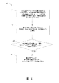
図4は、例示的な一実施態様によるマシンビジョンシステムの監視方法40を示している。マシンビジョンシステムは、少なくとも1つの照明装置、少なくとも1つの画像センサ、及びデータ処理装置を備える。ステップ41で、マシンビジョンシステムが、第1の動作モードで第1の物体、例えば材料ウェブを監視している。第1の動作モードでは、第1の物体が、第1の種類の照明を使用して前記少なくとも1つの照明装置によって照明され、該第1の物体の画像が、第1の撮像頻度で前記少なくとも1つの画像センサによって取り込まれ、該第1の物体が、第2の物体上に少なくとも部分的に配置されている。第2の物体は、例えば機械布であり得る。ステップ42で、取り込まれた画像の取り込まれた画像データが、解析のためにデータ処理装置に送信される。ステップ44で、マシンビジョンシステムが、ステップ43でデータ処理装置によって第1の物体が第2の物体上に存在しないことが検出された場合に、第2の動作モードで該第2の物体を監視するために切り替わる。
FIG. 4 shows a
多くの場合、第2の動作モードでは、第2の物体が、第2の種類の照明を使用して前記少なくとも1つの照明装置によって照明され、かつ該第2の物体の画像が、第2の撮像頻度で前記少なくとも1つの画像センサによって取り込まれ、第1の種類の照明が第2の種類の照明とは異なり、第2の撮像頻度が第1の撮像頻度とは異なる。しかしながら、第2の動作モードでは、第1の種類の照明を第2の種類の照明と同じにする、又は第2の撮像頻度を第1の撮像頻度と同じにすることも可能であり得る。 In many cases, in the second mode of operation, the second object is illuminated by the at least one illuminator using the second type of illumination, and the image of the second object is the second. The imaging frequency is captured by the at least one image sensor, the first type of illumination is different from the second type of illumination, and the second imaging frequency is different from the first imaging frequency. However, in the second mode of operation, it may be possible to make the first type of illumination the same as the second type of illumination, or the second imaging frequency the same as the first imaging frequency.
本発明の様々な実施態様は、メモリに存在して、装置に本発明を実施させるコンピュータプログラムコードの助けを借りて実施することができる。例えば、計算装置である装置、例えばデータ処理装置は、データを解析、受信、及び送信するための回路及び電子機器、メモリ内のコンピュータプログラムコード、並びにコンピュータプログラムコードを実行すると、装置に実施態様の特徴を実施させるプロセッサを備えることができる。プロセッサは、コンピュータプログラムコードを実行すると、以下の方法のステップを実行することができる:第1の動作モードにおいて第1の照明で画像センサ、例えばカメラセンサによって第1の物体の画像(複数可)を取り込むステップ、並びに該第1の物体が存在しないことが検出された場合に、第2の動作モードにおいて第2の照明で画像センサによって第2の物体の画像(複数可)を取り込むステップ。 Various embodiments of the invention are present in memory and can be implemented with the help of computer program code that causes the device to implement the invention. For example, a device that is a computing device, such as a data processing device, executes a circuit and electronic device for analyzing, receiving, and transmitting data, a computer program code in a memory, and a computer program code, and the device has an embodiment. It can be equipped with a processor that implements the features. When the processor executes the computer program code, it can perform the steps of the following method: an image of the first object (s) by an image sensor, eg, a camera sensor, with the first illumination in the first mode of operation. And a step of capturing an image (s) of the second object by the image sensor with the second illumination in the second operation mode when it is detected that the first object does not exist.
少なくとも画像センサ、例えば画像を取り込むのに適したカメラを備える従来のマシンビジョンシステムの方法及びシステムと比較すると、本発明によって重要な利点が達成される。本発明による構成により、マシンビジョンシステムが2つの異なる動作モードを有するため、共に少なくとも異なる種類の照明を必要とする2つの異なる物体に同じ画像センサを使用することが可能である。第1のモードは、第1の照明における第1の画像取り込み頻度でのイメージングを含み、第2のモードは、第2の照明における第2の画像取り込み頻度でのイメージングを含み、第1のイメージング標的が存在しないと検出されたときに、第1のモードから第2のモードへの動作モードの切り替えが行われ、該第1のイメージング標的が再び存在すると検出されたときに、該第2のモードから該第1のモードへの動作モードの切り替えが行われる。 Significant advantages are achieved by the present invention, at least when compared to the methods and systems of conventional machine vision systems equipped with image sensors, such as cameras suitable for capturing images. The configuration according to the invention allows the machine vision system to have two different modes of operation so that the same image sensor can be used for two different objects, both requiring at least different types of lighting. The first mode includes imaging at the first image capture frequency in the first illumination, and the second mode includes imaging at the second image capture frequency in the second illumination, the first imaging. When it is detected that the target does not exist, the operation mode is switched from the first mode to the second mode, and when it is detected that the first imaging target exists again, the second mode is performed. The operation mode is switched from the mode to the first mode.
本発明は、上記提示された実施態様のみに限定されるものではなく、添付の特許請求の範囲内で変更可能であることは明らかである。
本件出願は、以下の構成の発明を提供する。
(構成1)
少なくとも1つの照明装置、少なくとも1つの画像センサ、及びデータ処理装置を備えるマシンビジョンシステムの第1の動作モードで第1の物体を監視するステップであって、第1の種類の照明を使用して該少なくとも1つの照明装置によって該第1の物体を照明すること、及び第1の画像取り込み頻度で該少なくとも1つの画像センサによって該第1の物体の画像を取り込むことを含み、該第1の物体が、第2の物体上に少なくとも部分的に配置されている、該ステップ;
該取り込まれた画像の取り込まれた画像データを解析のために該データ処理装置に送信するステップ;並びに
該第1の物体が該第2の物体上に存在しないことが、該データ処理装置によって該第1の動作モードで取り込まれた該画像データから検出された場合に、第2の動作モードで該第2の物体を監視して、該取り込まれた画像の該取り込まれた画像データを解析のために該データ処理装置に送信するために該マシンビジョンシステムを切り替えるステップであって、該第2の動作モードにおいて、該少なくとも1つの画像センサが、監視されるべき該第2の物体から第2の画像取り込み頻度で画像を取り込むように再構成される、該ステップを含む、方法。
(構成2)
前記第2の動作モードにおいて、前記少なくとも1つの照明装置が、監視されるべき前記第2の物体を照明するための第2の種類の照明を使用するように再構成される、構成1記載の方法。
(構成3)
前記第2の動作モードにおいて、前記データ処理装置が、監視されるべき前記第2の物体の異常を検出するのに適するように再構成された画像解析パラメータを用いて、監視されるべき該第2の物体の取り込まれた画像データから異常を検出するように構成されている、構成1又は2記載の方法。
(構成4)
前記第1の物体が前記第2の物体上に存在しないことが、前記取り込まれた画像データから前記データ処理装置によって検出される、構成1~3のいずれか一項記載の方法。
(構成5)
前記第1の物体が前記第2の物体上に存在しないことが、抄紙機制御システムから受信した受信外部指示信号から検出される、構成1~3のいずれか一項記載の方法。
(構成6)
前記第1の物体が材料ウェブであり、前記第2の物体が機械布である、構成1~5のいずれか一項記載の方法。
(構成7)
前記第2の動作モードで前記第2の物体上に前記第1の物体が存在することが、前記データ処理装置によって前記第2の動作モードで取り込まれた画像データから検出された場合に、前記第1の動作モードで監視するために前記マシンビジョンシステムを切り替えるステップをさらに含む、構成1~6のいずれか一項記載の方法。
(構成8)
少なくとも1つの照明装置、少なくとも1つの画像センサ、及びデータ処理装置を備えるマシンビジョンシステムであって、第1の動作モードで第1の物体を監視し、第2の動作モードで第2の物体を監視するように構成され、該第1動作モードにおいて、少なくとも1つの照明装置が、第1の種類の照明を使用して該第1の物体を照明するように構成され、かつ該画像センサが、第1の画像取り込み頻度で第1の物体の画像を取り込み、該取り込まれた画像データを解析のために該データ処理装置に送信するように構成され、該第1の物体が該第2の物体上に存在しないことが該データ処理装置によって該取り込まれた画像データから検出された場合に、該マシンビジョンシステムが、第2の動作モードで該第2の物体を監視し、該取り込まれた画像の該取り込まれた画像データを解析のために該データ処理装置に送信するために第2の動作モードに切り替えられ、該第2の動作モードにおいて、該少なくとも1つの画像センサが、監視されるべき該第2の物体から第2の画像取り込み頻度で画像を取り込むように再構成される、前記マシンビジョンシステム。
(構成9)
前記第2の動作モードにおいて、前記少なくとも1つの照明装置が、監視されるべき前記第2の物体を照明するための第2の種類の照明を使用するように再構成される、構成8記載のマシンビジョンシステム。
(構成10)
前記第2の動作モードにおいて、前記データ処理装置が、監視されるべき前記第2の物体における異常を検出するのに適するように再構成された画像解析パラメータを用いて、監視されるべき該第2の物体の取り込まれた画像データから異常を検出するように構成されている、構成8又は9記載のマシンビジョンシステム。
(構成11)
前記第1の物体が前記第2の物体上に存在しないことが、前記取り込まれた画像データから前記データ処理装置によって検出されるか、又は抄紙機制御システムから受信した受信外部指示信号から検出される、構成8~10のいずれか一項記載のマシンビジョンシステム。
(構成12)
前記第1の物体が材料ウェブであり、前記第2の物体が機械布である、構成8~11のいずれか一項記載のマシンビジョンシステム。
(構成13)
前記方法が:前記第1の物体が前記第2の物体上に存在することが前記データ処理装置によって前記第2の動作モードで検出された場合に、前記第1の動作モードで前記第1の物体を監視するために前記マシンビジョンシステムを切り替えるステップをさらに含む、構成8~12のいずれか一項記載のマシンビジョンシステム。
(構成14)
コンピュータ可読媒体に格納された、計算装置で実行可能なコンピュータプログラム製品であって、構成1~7のいずれか一項記載の方法を実施するための命令を含む、前記コンピュータプログラム製品。
It is clear that the present invention is not limited to the embodiments presented above, but can be modified within the scope of the appended claims.
The present application provides an invention having the following constitution.
(Structure 1)
A step of monitoring a first object in a first mode of operation of a machine vision system with at least one lighting device, at least one image sensor, and a data processing device, using the first type of lighting. The first object comprises illuminating the first object with the at least one lighting device and capturing an image of the first object with the at least one image sensor at a first image capture frequency. Is at least partially located on the second object, said step;
The step of transmitting the captured image data of the captured image to the data processing device for analysis;
When the absence of the first object on the second object is detected in the image data captured in the first operation mode by the data processing device, the first object is said to be present in the second operation mode. The second step is to monitor the second object and switch the machine vision system to send the captured image data of the captured image to the data processing device for analysis. A method comprising the step, wherein in the mode of operation, the at least one image sensor is reconfigured to capture an image from the second object to be monitored at a second image capture frequency.
(Structure 2)
1. In configuration 1, wherein in the second mode of operation, the at least one luminaire is reconfigured to use a second type of illuminating for illuminating the second object to be monitored. Method.
(Structure 3)
In the second mode of operation, the data processing device should be monitored using image analysis parameters reconfigured to be suitable for detecting anomalies in the second object to be monitored. 2. The method according to configuration 1 or 2, which is configured to detect anomalies from captured image data of an object in 2.
(Structure 4)
The method according to any one of configurations 1 to 3, wherein it is detected by the data processing apparatus from the captured image data that the first object does not exist on the second object.
(Structure 5)
The method according to any one of configurations 1 to 3, wherein the absence of the first object on the second object is detected from a received external instruction signal received from the paper machine control system.
(Structure 6)
The method according to any one of configurations 1 to 5, wherein the first object is a material web and the second object is a mechanical cloth.
(Structure 7)
When the presence of the first object on the second object in the second operation mode is detected from the image data captured in the second operation mode by the data processing device, the said. The method of any one of configurations 1-6, further comprising the step of switching the machine vision system for monitoring in the first mode of operation.
(Structure 8)
A machine vision system with at least one lighting device, at least one image sensor, and a data processing device that monitors a first object in a first mode of operation and a second object in a second mode of operation. Configured to monitor, in the first mode of operation, at least one lighting device is configured to illuminate the first object using the first type of lighting, and the image sensor. The image of the first object is captured at the frequency of capturing the first image, and the captured image data is transmitted to the data processing device for analysis, and the first object is the second object. When the data processing device detects from the captured image data that it is not present, the machine vision system monitors the second object in the second operating mode and the captured image. The captured image data is switched to a second operating mode for transmission to the data processing device for analysis, in which the at least one image sensor should be monitored. The machine vision system reconfigured to capture images from the second object at a second image capture frequency.
(Structure 9)
8. In configuration 8, wherein in the second mode of operation, the at least one luminaire is reconfigured to use a second type of illuminating for illuminating the second object to be monitored. Machine vision system.
(Structure 10)
In the second mode of operation, the data processing apparatus should be monitored using image analysis parameters reconfigured to be suitable for detecting anomalies in the second object to be monitored. 2. The machine vision system according to configuration 8 or 9, which is configured to detect anomalies from captured image data of an object in 2.
(Structure 11)
The absence of the first object on the second object is detected by the data processing apparatus from the captured image data or from a received external instruction signal received from the papermaking machine control system. The machine vision system according to any one of the configurations 8 to 10.
(Structure 12)
The machine vision system according to any one of configurations 8 to 11, wherein the first object is a material web and the second object is a machine cloth.
(Structure 13)
The method: The first in the first operating mode when the data processing apparatus detects that the first object is on the second object in the second operating mode. 13. The machine vision system according to any one of configurations 8-12, further comprising the step of switching the machine vision system to monitor an object.
(Structure 14)
A computer program product stored in a computer-readable medium that can be executed by a computer and includes instructions for carrying out the method according to any one of configurations 1 to 7.
Claims (9)
該取り込まれた画像の取り込まれた画像データを解析のために該データ処理装置(13、16)に送信するステップを含む方法であって;かつ
該第1の物体(17a)が該第2の物体(17b)上に存在しないことが、該データ処理装置(13、16)による該取り込まれた画像データの解析により該第1の動作モードで取り込まれた該画像データから検出された場合に、第2の動作モードで該第2の物体(17b)を監視して、該取り込まれた画像の該取り込まれた画像データを解析のために該データ処理装置(13、16)に送信するために該データ処理装置(13、16)によって再構成信号を送信することにより該マシンビジョンシステム(10)を再構成するステップであって、該第2の動作モードにおいて、該少なくとも1つの画像センサ(12、15)が、監視されるべき該第2の物体(17b)から第2の画像取り込み頻度で画像を取り込むように構成され、かつ該データ処理装置(13、16)が、監視されるべき該第2の物体の異常を検出するのに適するように構成された画像解析パラメータを用いて、該第2の物体(17b)の該取り込まれた画像データから異常を検出するように構成されている、該ステップをさらに含むことを特徴とする、前記方法。 A first object in a first operating mode of a machine vision system (10) with at least one lighting device (18, 19), at least one image sensor (12, 15), and a data processing device (13, 16). The first type of lighting is used to illuminate the first object (17a) with the at least one lighting device (18, 19), and the first image capture frequency. Including capturing an image of the first object (17a) by the at least one image sensor (12, 15), the first object (17a) is placed on the second object (17b). A method comprising the steps of transmitting the captured image data of the captured image to the data processing apparatus (13, 16) for analysis; and the first object (the first object). The absence of 17a) on the second object (17b) means that the captured image data captured in the first operating mode by analysis of the captured image data by the data processing apparatus (13, 16). When detected from, the second object (17b) is monitored in the second operating mode and the captured image data of the captured image is analyzed by the data processing device (13, It is a step of reconstructing the machine vision system (10) by transmitting a reconstruction signal by the data processing apparatus (13, 16) for transmission to 16), and in the second operation mode, the said. At least one image sensor (12, 15) is configured to capture images from the second object (17b) to be monitored at a second image capture frequency, and the data processor (13, 16). Detects anomalies in the captured image data of the second object (17b) using image analysis parameters configured to be suitable for detecting anomalies in the second object to be monitored. The method, characterized in that it further comprises the step, which is configured to:
該第1の物体(17a)が該第2の物体(17b)上に存在しないことが該データ処理装置(13、16)によって該取り込まれた画像データから検出された場合に、該マシンビジョンシステム(10)が、第2の動作モードで該第2の物体(17b)を監視し、該取り込まれた画像の該取り込まれた画像データを解析のために該データ処理装置(13、16)に送信するために該データ処理装置(13、16)によって送信された再構成信号によって該第2の動作モードに再構成され、該第2の動作モードにおいて、該少なくとも1つの画像センサ(12、15)が、監視されるべき該第2の物体(17b)から第2の画像取り込み頻度で画像を取り込むように構成され、かつ該データ処理装置(13、16)が、監視されるべき該第2の物体における異常を検出するのに適するように構成された画像解析パラメータを用いて、該第2の物体(17b)の該取り込まれた画像データから異常を検出するように構成されていることを特徴とする、前記マシンビジョンシステム。 A machine vision system (10) comprising at least one lighting device (18, 19), at least one image sensor (12, 15), and a data processing device (13, 16), said machine vision system (10). Is configured to monitor the first object (17a) in the first mode of operation and the second object (17b) in the second mode of operation, and at least in the first mode of operation. One illuminator (18, 19) is configured to illuminate the first object (17a) using the first type of illumination, and the image sensor (12, 15) is the first. The image of the first object (17a) is captured at the image capture frequency of the above, and the captured image data is transmitted to the data processing apparatus (13, 16) for analysis, and the first image is captured. The machine vision system (10) determines that the object (17a) is not present on the second object (17b) from the captured image data by the data processing apparatus (13, 16). , To monitor the second object (17b) in the second mode of operation and send the captured image data of the captured image to the data processing apparatus (13, 16) for analysis. The reconstruction signal transmitted by the data processing apparatus (13, 16) reconfigures the second operating mode, in which the at least one image sensor (12, 15) monitors. Anomalies in the second object that are configured to capture images from the second object (17b) to be captured at a second image capture frequency and that the data processing apparatus (13, 16) should be monitored. It is characterized in that it is configured to detect anomalies from the captured image data of the second object (17b) using image analysis parameters configured to be suitable for detecting. The machine vision system.
Applications Claiming Priority (3)
| Application Number | Priority Date | Filing Date | Title |
|---|---|---|---|
| FI20165387 | 2016-05-06 | ||
| FI20165387A FI128850B (en) | 2016-05-06 | 2016-05-06 | A machine vision method and system for monitoring manufacturing processes |
| PCT/FI2017/050325 WO2017191363A1 (en) | 2016-05-06 | 2017-04-28 | A machine vision method and system for monitoring manufacturing processes |
Publications (3)
| Publication Number | Publication Date |
|---|---|
| JP2019518943A JP2019518943A (en) | 2019-07-04 |
| JP2019518943A5 JP2019518943A5 (en) | 2020-05-21 |
| JP7090032B2 true JP7090032B2 (en) | 2022-06-23 |
Family
ID=60202816
Family Applications (1)
| Application Number | Title | Priority Date | Filing Date |
|---|---|---|---|
| JP2018558234A Active JP7090032B2 (en) | 2016-05-06 | 2017-04-28 | Machine vision methods and systems for monitoring manufacturing processes |
Country Status (8)
| Country | Link |
|---|---|
| US (1) | US10884401B2 (en) |
| EP (2) | EP4019948A1 (en) |
| JP (1) | JP7090032B2 (en) |
| CN (1) | CN109416327B (en) |
| ES (1) | ES2923908T3 (en) |
| FI (1) | FI128850B (en) |
| PL (1) | PL3452811T3 (en) |
| WO (1) | WO2017191363A1 (en) |
Families Citing this family (8)
| Publication number | Priority date | Publication date | Assignee | Title |
|---|---|---|---|---|
| EP3805733B1 (en) | 2018-05-31 | 2023-10-25 | PSM International, Inc. | Quality measuring method and quality measuring device for long sheet material |
| FI128235B (en) * | 2018-12-10 | 2020-01-15 | Procemex Oy Ltd | Overhead sidelight |
| JP7269126B2 (en) * | 2019-07-31 | 2023-05-08 | ファナック株式会社 | Imaging detection data transmission system |
| CN111650208B (en) * | 2020-06-01 | 2021-08-27 | 东华大学 | Tour type woven fabric defect on-line detector |
| US20230213458A1 (en) * | 2021-12-30 | 2023-07-06 | CreateMe Technologies LLC | Automated inspection measurement in garment manufacturing |
| CN115201201B (en) * | 2022-06-24 | 2023-08-01 | 广东工业大学 | Forming mesh quality detection method based on machine vision |
| US11932991B2 (en) * | 2022-08-03 | 2024-03-19 | Industrial Video Solutions Inc. | Systems and methods for monitoring and controlling industrial processes |
| US11816893B1 (en) | 2022-08-03 | 2023-11-14 | Industrial Video Solutions Inc. | Systems and methods for monitoring and controlling industrial processes |
Citations (5)
| Publication number | Priority date | Publication date | Assignee | Title |
|---|---|---|---|---|
| JP2000118659A (en) | 1998-10-15 | 2000-04-25 | Albany Internatl Corp | Endless belt or endless cloth for process control loop |
| JP2004226328A (en) | 2003-01-24 | 2004-08-12 | Hitachi Ltd | Appearance inspection system, quality evaluation system using the same and quality evaluation information providing system |
| US20060096726A1 (en) | 2002-03-27 | 2006-05-11 | Metso Paper, Inc. | Method and system for maintaining runnability in a paper or board machine |
| US20090060316A1 (en) | 2006-02-22 | 2009-03-05 | Hannu Ruuska | Method for Monitoring a Rapidly-Moving Paper Web and Corresponding System |
| CN202221415U (en) | 2011-09-03 | 2012-05-16 | 山东轻工业学院 | Surface defect online detection system for wide breadth paper |
Family Cites Families (25)
| Publication number | Priority date | Publication date | Assignee | Title |
|---|---|---|---|---|
| US4845374A (en) | 1987-07-20 | 1989-07-04 | R. J. Reynolds Tobacco Company | Method and apparatus for detecting the deposition of an adhesive on a travelling web |
| DE4216653C2 (en) * | 1992-05-20 | 1995-12-21 | Voith Gmbh J M | Tear monitoring device for paper webs |
| US5314072A (en) | 1992-09-02 | 1994-05-24 | Rutgers, The State University | Sorting plastic bottles for recycling |
| US5815198A (en) | 1996-05-31 | 1998-09-29 | Vachtsevanos; George J. | Method and apparatus for analyzing an image to detect and identify defects |
| JP2000111483A (en) * | 1998-10-02 | 2000-04-21 | Dainippon Printing Co Ltd | Method and apparatus for inspection of cyclic pattern |
| JP2000111493A (en) | 1998-10-03 | 2000-04-21 | Kenji Shibahara | Inspection method for surface state |
| US6750466B2 (en) | 2001-02-09 | 2004-06-15 | Wintriss Engineering Corporation | Web inspection system |
| FI115588B (en) * | 2001-11-02 | 2005-05-31 | Metso Automation Oy | Camera Interface |
| FI115163B (en) | 2001-11-29 | 2005-03-15 | Metso Automation Oy | Quality and condition control according to spectrum discriminant measurement |
| DE10249385A1 (en) | 2002-10-23 | 2004-05-06 | Voith Paper Patent Gmbh | Method and device for monitoring the condition of a covering |
| DE10343517A1 (en) | 2003-09-19 | 2005-05-04 | Voith Paper Patent Gmbh | Method and arrangement for determining the water permeability of a fabric |
| FI118775B (en) | 2005-05-12 | 2008-03-14 | Metso Paper Inc | Method and apparatus for checking the condition of a shoe roller |
| FI119708B (en) * | 2006-02-01 | 2009-02-13 | Viconsys Oy | Device for checking a path |
| DE102006055823A1 (en) | 2006-11-27 | 2008-05-29 | Voith Patent Gmbh | Method for detecting a tear of a fibrous web in a dryer section of a machine for producing the fibrous web and drying wire for carrying out the method |
| US8355581B2 (en) | 2007-03-06 | 2013-01-15 | Advanced Vision Technology (Avt) Ltd. | System and method for detecting the contour of an object on a moving conveyor belt |
| US20090028417A1 (en) | 2007-07-26 | 2009-01-29 | 3M Innovative Properties Company | Fiducial marking for multi-unit process spatial synchronization |
| DE102007045895A1 (en) * | 2007-09-26 | 2009-04-09 | Voith Patent Gmbh | A band calendering apparatus and method of operating a band calendering apparatus |
| US7986410B2 (en) * | 2008-03-18 | 2011-07-26 | Voith Patent Gmbh | Method for detecting a fibrous web tear in a drying section of a machine for producing the fibrous web and apparatus for performing said method |
| FI20106053A0 (en) * | 2010-10-13 | 2010-10-13 | Metso Automation Oy | Track monitoring system and corresponding track monitoring method |
| DE102011078010A1 (en) * | 2011-06-22 | 2012-12-27 | Voith Patent Gmbh | Method for monitoring homogeneous properties of cover for transportation of paper web through dry end of paper machine, involves determining degree of contamination by judging contrast between clean and contaminated surface portions |
| US8591703B2 (en) | 2011-07-06 | 2013-11-26 | Voith Patent Gmbh | Monofilament yarn for a paper machine clothing fabric |
| DE102011113670A1 (en) * | 2011-09-20 | 2013-03-21 | Schott Ag | Lighting device, inspection device and inspection method for the optical inspection of an object |
| FI125725B (en) * | 2011-11-15 | 2016-01-29 | Valmet Technologies Oy | Method and apparatus for following a fiber web |
| DE102012208201A1 (en) * | 2012-05-16 | 2013-11-21 | Voith Patent Gmbh | Method for detecting contamination of a paper machine clothing |
| FI128403B (en) | 2013-07-05 | 2020-04-30 | Procemex Oy Ltd | Synchronization of imaging |
-
2016
- 2016-05-06 FI FI20165387A patent/FI128850B/en active IP Right Grant
-
2017
- 2017-04-28 EP EP22157040.1A patent/EP4019948A1/en active Pending
- 2017-04-28 PL PL17792559.1T patent/PL3452811T3/en unknown
- 2017-04-28 EP EP17792559.1A patent/EP3452811B1/en active Active
- 2017-04-28 US US16/095,790 patent/US10884401B2/en active Active
- 2017-04-28 JP JP2018558234A patent/JP7090032B2/en active Active
- 2017-04-28 CN CN201780028058.9A patent/CN109416327B/en active Active
- 2017-04-28 ES ES17792559T patent/ES2923908T3/en active Active
- 2017-04-28 WO PCT/FI2017/050325 patent/WO2017191363A1/en active Search and Examination
Patent Citations (5)
| Publication number | Priority date | Publication date | Assignee | Title |
|---|---|---|---|---|
| JP2000118659A (en) | 1998-10-15 | 2000-04-25 | Albany Internatl Corp | Endless belt or endless cloth for process control loop |
| US20060096726A1 (en) | 2002-03-27 | 2006-05-11 | Metso Paper, Inc. | Method and system for maintaining runnability in a paper or board machine |
| JP2004226328A (en) | 2003-01-24 | 2004-08-12 | Hitachi Ltd | Appearance inspection system, quality evaluation system using the same and quality evaluation information providing system |
| US20090060316A1 (en) | 2006-02-22 | 2009-03-05 | Hannu Ruuska | Method for Monitoring a Rapidly-Moving Paper Web and Corresponding System |
| CN202221415U (en) | 2011-09-03 | 2012-05-16 | 山东轻工业学院 | Surface defect online detection system for wide breadth paper |
Non-Patent Citations (1)
| Title |
|---|
| LAUNONEN, U. et al.,The latest machine vision tools for paper machines,Appita,2014年,Vol. 67, No.2,pp. 109-114 |
Also Published As
| Publication number | Publication date |
|---|---|
| EP3452811A1 (en) | 2019-03-13 |
| EP3452811A4 (en) | 2020-01-22 |
| US10884401B2 (en) | 2021-01-05 |
| US20190129396A1 (en) | 2019-05-02 |
| CN109416327A (en) | 2019-03-01 |
| WO2017191363A1 (en) | 2017-11-09 |
| EP4019948A1 (en) | 2022-06-29 |
| FI20165387A (en) | 2017-11-07 |
| PL3452811T3 (en) | 2022-10-10 |
| CN109416327B (en) | 2021-10-26 |
| JP2019518943A (en) | 2019-07-04 |
| FI128850B (en) | 2021-01-29 |
| EP3452811B1 (en) | 2022-05-25 |
| ES2923908T3 (en) | 2022-10-03 |
Similar Documents
| Publication | Publication Date | Title |
|---|---|---|
| JP7090032B2 (en) | Machine vision methods and systems for monitoring manufacturing processes | |
| JP5881278B2 (en) | Cloth piece inspection apparatus and inspection method | |
| JP2019518943A5 (en) | ||
| WO2006054545A1 (en) | Automatic judging device and automatic judging method | |
| US9701506B2 (en) | Monitoring system and apparatus comprising such a monitoring system | |
| JP2008308335A (en) | Traveling yarn line inspection method and carbon fiber manufacturing method using the same | |
| JP6902051B2 (en) | Machine vision methods and systems | |
| JP2009285109A (en) | Folding machine with inspection function | |
| KR100364936B1 (en) | Monitoring apparatus | |
| JP4903031B2 (en) | Apparatus and method for inspecting appearance of sheet material having translucency | |
| CN112752881B (en) | Monitoring system | |
| FI128820B (en) | A machine vision method and system for monitoring manufacturing processes | |
| US7138036B2 (en) | Monitoring device | |
| JP5818948B2 (en) | Cloth piece inspection device | |
| JP2021128110A (en) | Belt conveyor monitoring device | |
| JP2001175866A (en) | Device and method for image process inspection | |
| JP2019039697A (en) | Laminated sheet defect inspection device and sheet product manufacturing method | |
| JP2003213585A (en) | Apparatus for monitoring paper quality, paper machine and method for making paper | |
| JP7061841B2 (en) | Diagnostic equipment and systems for linen equipment | |
| JP2020107605A5 (en) | ||
| JP6216591B2 (en) | Sheet material appearance inspection device | |
| KR970053189A (en) | Image inspection apparatus and method for staggered wire bonding | |
| JP2001255129A (en) | Surface stain inspection device for bobbin package | |
| JP2005240217A (en) | Monitor |
Legal Events
| Date | Code | Title | Description |
|---|---|---|---|
| A521 | Request for written amendment filed |
Free format text: JAPANESE INTERMEDIATE CODE: A523 Effective date: 20200324 |
|
| A621 | Written request for application examination |
Free format text: JAPANESE INTERMEDIATE CODE: A621 Effective date: 20200324 |
|
| A977 | Report on retrieval |
Free format text: JAPANESE INTERMEDIATE CODE: A971007 Effective date: 20201218 |
|
| A131 | Notification of reasons for refusal |
Free format text: JAPANESE INTERMEDIATE CODE: A131 Effective date: 20210126 |
|
| A521 | Request for written amendment filed |
Free format text: JAPANESE INTERMEDIATE CODE: A523 Effective date: 20210426 |
|
| A131 | Notification of reasons for refusal |
Free format text: JAPANESE INTERMEDIATE CODE: A131 Effective date: 20211012 |
|
| A521 | Request for written amendment filed |
Free format text: JAPANESE INTERMEDIATE CODE: A523 Effective date: 20211224 |
|
| TRDD | Decision of grant or rejection written | ||
| A01 | Written decision to grant a patent or to grant a registration (utility model) |
Free format text: JAPANESE INTERMEDIATE CODE: A01 Effective date: 20220517 |
|
| A61 | First payment of annual fees (during grant procedure) |
Free format text: JAPANESE INTERMEDIATE CODE: A61 Effective date: 20220613 |
|
| R150 | Certificate of patent or registration of utility model |
Ref document number: 7090032 Country of ref document: JP Free format text: JAPANESE INTERMEDIATE CODE: R150 |