EP4019733A1 - Pass-through lock - Google Patents
Pass-through lock Download PDFInfo
- Publication number
- EP4019733A1 EP4019733A1 EP21000359.6A EP21000359A EP4019733A1 EP 4019733 A1 EP4019733 A1 EP 4019733A1 EP 21000359 A EP21000359 A EP 21000359A EP 4019733 A1 EP4019733 A1 EP 4019733A1
- Authority
- EP
- European Patent Office
- Prior art keywords
- passage
- passage lock
- ring segment
- lock
- lock according
- Prior art date
- Legal status (The legal status is an assumption and is not a legal conclusion. Google has not performed a legal analysis and makes no representation as to the accuracy of the status listed.)
- Pending
Links
Images


Classifications
-
- E—FIXED CONSTRUCTIONS
- E06—DOORS, WINDOWS, SHUTTERS, OR ROLLER BLINDS IN GENERAL; LADDERS
- E06B—FIXED OR MOVABLE CLOSURES FOR OPENINGS IN BUILDINGS, VEHICLES, FENCES OR LIKE ENCLOSURES IN GENERAL, e.g. DOORS, WINDOWS, BLINDS, GATES
- E06B3/00—Window sashes, door leaves, or like elements for closing wall or like openings; Layout of fixed or moving closures, e.g. windows in wall or like openings; Features of rigidly-mounted outer frames relating to the mounting of wing frames
- E06B3/90—Revolving doors; Cages or housings therefor
- E06B3/903—Revolving doors; Cages or housings therefor consisting of arcuate wings revolving around a parallel axis situated outside the wing, e.g. a cylindrical wing revolving around its axis
-
- E—FIXED CONSTRUCTIONS
- E06—DOORS, WINDOWS, SHUTTERS, OR ROLLER BLINDS IN GENERAL; LADDERS
- E06B—FIXED OR MOVABLE CLOSURES FOR OPENINGS IN BUILDINGS, VEHICLES, FENCES OR LIKE ENCLOSURES IN GENERAL, e.g. DOORS, WINDOWS, BLINDS, GATES
- E06B11/00—Means for allowing passage through fences, barriers or the like, e.g. stiles
- E06B11/08—Turnstiles; Gates for control of entry or exit of persons, e.g. in supermarkets
Definitions
- the invention relates to a passage lock for a passage delimited by blocking or guiding elements according to the preamble of claim 1 and to methods for using such a passage lock with the features of claims 13 and 14.
- a large number of transit locks are known.
- the simplest embodiment is that of a swing door, which can be found in almost every supermarket, for example.
- a door leaf is arranged on a pillar, which can be pivoted about its vertical axis and thus opens or blocks the passage. The pivoting movement can be carried out manually or with an electric motor.
- a similar device is in CA 2 267 394C shown and described. There, several barriers arranged linearly one behind the other are proposed for a passage lock.
- a relatively elaborately designed passage barrier can be found in DE 20 2017 000 978 U1 , in which a turnstile is arranged in a turnstile, through which the passage through the turnstile is alternately released or blocked.
- a rotation unit comprises a plurality of barrier bars, which each block the passage after sweeping over a rotation section.
- a similar device is in the DE 20 2005 012 659 U1 as well as in the NL 9201749 shown as a turnstile. With these turnstiles, after one person has passed through, the subsequent blocking arm prevents the passage of another person.
- Such a device is also in the DE 196 12 328 A1 shown and described.
- the special feature of this turnstile is that the locking arms are curved.
- the present invention is based on the object of creating a device for separating people and allowing them to pass through or blocking their passage, as well as specifying a method for using such a device.
- a device is in the form of a. Created a passage lock, with a passage limited by blocking or guide elements, with a blocking element that can be rotated about a vertical axis between a blocking position and a passage position, in which the blocking element is designed in the form of a ring segment and is mounted in a blocking element holder so that it can rotate horizontally, and in which at least one drive element in the locking element holder is in operative connection with the ring segment.
- the blocking element holder consists essentially of a pillar, the one at its free end Carrying drive cage, the interior of which is penetrated by the ring segment, and when the drive element corresponds to the contour of the ring segment.
- a pass-through lock is designed particularly advantageously if the ring segment is driven by a frictional connection between its contour and the drive element, in particular if the drive is realized by opposite, electrically operated friction wheels, between which the contour is accommodated and the ring segment can be moved by friction, where several pairs of opposing friction wheels can be present.
- a passage lock can also be designed advantageously if the ring segment is driven by a positive fit between its contour and the drive element.
- a passage lock is particularly advantageous when the ring segment is elliptical or in the special elliptical shape of a torus segment.
- the drive cage, including the blocking element, and the standing column are connected by means of a joint.
- a transit lock is also advantageously designed if it has sensors and/or display elements and/or interfaces for wireless information transmission.
- the transit lock and/or the ring segment can be used as an advertising medium, information medium and the like and also display warnings. Through an interface, maintenance, control and other settings can be simplified.
- a passage lock is equipped particularly advantageously if the ring segment contains sensors and/or display elements and/or interfaces for wireless information transmission, as explained above.
- the through lock 1 has a blocking element holder in the form of a vertical column 4 .
- a drive cage 5 At the free end of the sand column 4 there is a drive cage 5 whose interior space 6 is penetrated by a blocking element 7 .
- This blocking element 7 consists of a ring segment 8 which is mounted in the drive cage 5 so as to oscillate horizontally in rotation, with the oscillating movement of the blocking element 7 essentially taking place on a horizontal circular path.
- the passage through the passage lock 1 is released or blocked.
- FIG 2 is shown schematically in a spatial plan view of the interior 6 of the drive cage 5.
- the path of the oscillating ring segment 8 runs through this interior space 6 .
- Two electric motors 9 and 10 synchronized with one another each drive a drive unit 11 and 12 .
- Each drive unit 11 and 12 has a pair of friction wheels 13, 14 and 15, 16, between which the ring segment 8 is guided and transported with as little slippage as possible.
- FIG 3 is supplementary to figure 2 the drive cage 5 is shown in plan view with a view of the interior 6 .
- Both electric motors 9 and 10 with the drive units 11 and 12 assigned to them can be seen:
- the friction wheel pairs 13, 14 and 15, 16 clearly hold the ring segment 8 between them.
- Set in rotation by the two electric motors 9 and 10, the friction wheel pairs 13, 14 and 15, 16 drive the latter due to their friction with the contour 17 of the ring segment 8, so that it is moved on a circular path.
- the electric motors 9 and 10 are reversed so that the friction wheel pairs 13, 14 and 15, 16 of the drive units 11 and 12 change their direction of rotation and move the ring segment 8 back on its circular path.
- Figures 4a to 4d different views and positions of the passage lock 1 are illustrated in a highly schematic manner.
- Figure 4a shows a passage lock 1 in plan view and in the "closed” state.
- the pillar 4 with the drive cage 5 is arranged between two blocking or guiding elements 2 and 3 .
- the ring segment 8 is "locked” in its end position, as a result of which passage between the locking or guiding elements 2 and 3 is prevented.
- Figure 4b shows the same state of the passage lock 1 in front view.
- FIG. 4c Another significant advantage of the passage lock 1 according to the invention is its behavior in the event of a fault. This is from the Figures 4c and 4d apparent. Analogous to Figure 4a indicates Figure 4c a plan view of the passage lock 1, but here in an emergency position. Since in an emergency the passage between the blocking or guiding elements 2 and 3 must be released, the drive cage 5 tilts into a vertical position in such a situation, which is made possible by a joint 18 between the support column 4 and the drive cage 5 .
- the ring segment 8 as a blocking element 7 follows the tilting movement of the drive cage 5 and lies parallel to the vertical column 4, so that the passage between the blocking or guiding elements 2 and 3 can be passed largely unhindered.
- the emergency message can be triggered manually, automatically or remotely. Even in the event of a power failure, the aforementioned necessary steps to release the passage are triggered. When the emergency situation or the power failure has been resolved, that is to say is over, the drive cage 5 with the blocking element 7 is automatically returned to its normal working position.
- Figure 4d Figure 1 shows the front view of the passage lock 1 in the emergency position.
- the vertical position of the blocking element 7 parallel to the pillar 4 can be seen.
- the closing or opening movement describes a ring segment on a circular path around the longitudinal axis of the body of the respective person who is passing through the passage lock.
Abstract
Bei einer Durchgangsschleuse (1) ist das Sperrelement (7) in Form eines Ringsegments (8) ausgebildet und in einer Sperrelementhalterung (4) horizontal rotationspendelnd gelagert, wobei wenigstens ein Antriebselement (11, 12) in der Sperrelementhalterung (4) mit dem Ringsegment (8) in Wirkverbindung steht (Figur 1).In a through lock (1), the blocking element (7) is designed in the form of a ring segment (8) and is mounted in a blocking element holder (4) so that it can rotate horizontally, with at least one drive element (11, 12) in the blocking element holder (4) being connected to the ring segment ( 8) is in operative connection (Figure 1).
Description
Die Erfindung bezieht sich auf eine Durchgangsschleuse für einen von Sperr- oder Leitelementen begrenzten Durchgang gemäß dem Oberbegriff des Anspruchs 1 sowie auf Verfahren zur Anwendung einer derartigen Durchgangsschleuse mit den Merkmalen der Ansprüche 13 und 14.The invention relates to a passage lock for a passage delimited by blocking or guiding elements according to the preamble of
Es ist eine Vielzahl von Durchgangsschleusen bekannt. Die einfachste Ausführungsform ist die einer Schwenktür, die beispielsweise in fast jedem Supermarkt zu finden ist. Beispielhaft ist eine derartige Durchgangssperre in der
In der
Eine weitere Bauform ist in der
Eine ähnliche Vorrichtung ist in der
Ferner ist in der
Eine verhältnismäßig aufwändig gestaltete Durchgangssperre findet sich in der
Eine weitere Vorrichtung zur Personenvereinzelung ist in der
Eine ähnliche Einrichtung wird in der
Eine derartige Vorrichtung ist auch in der
Diesem beispielhaft dargestellten Stand der Technik haften Nachteile an. So ist es für Personen mit Gepäck oder Kinderwagen und dergleichen oftmals schwierig, derartige Sperren zu überwinden.This prior art, which is presented as an example, has disadvantages. It is often difficult for people with luggage or strollers and the like to overcome such barriers.
Der vorliegenden Erfindung liegt die Aufgabe zugrunde, eine Vorrichtung zur Vereinzelung von Personen und deren Durchgang oder Sperrung ihres Durchgangs zu schaffen, so wie Verfahren zur Anwendung einer derartigen Vorrichtung anzugeben.The present invention is based on the object of creating a device for separating people and allowing them to pass through or blocking their passage, as well as specifying a method for using such a device.
Eine erfindungsgemäße Vorrichtung wird in Form einer. Durchgangsschleuse geschaffen, mit einem für von Sperr- oder Leitelementen begrenzten Durchgang, mit einem zwischen einer Sperrposition und einer Durchgangsposition um eine vertikale Achse drehbaren Sperrelement, bei der das Sperrelement in Form eines Ringsegments ausgebildet und in einer Sperrelementhalterung horizontal rotationspendelnd gelagert ist, und bei der wenigstens ein Antriebselement in der Sperrelementhalterung mit dem Ringsegment in Wirkverbindung steht.A device according to the invention is in the form of a. Created a passage lock, with a passage limited by blocking or guide elements, with a blocking element that can be rotated about a vertical axis between a blocking position and a passage position, in which the blocking element is designed in the form of a ring segment and is mounted in a blocking element holder so that it can rotate horizontally, and in which at least one drive element in the locking element holder is in operative connection with the ring segment.
Eine derartige Durchgangsschleuse ist vorteilhaft, wenn die Sperrelementhalterung im Wesentlichen aus einer Standsäule besteht, die an ihrem freien Ende einen Antriebskäfig trägt, dessen Innenraum von dem Ringsegment durchdrungen wird, und wenn das Antriebselement mit der Kontur des Ringsegments korrespondiert.Such a passage sluice is advantageous if the blocking element holder consists essentially of a pillar, the one at its free end Carrying drive cage, the interior of which is penetrated by the ring segment, and when the drive element corresponds to the contour of the ring segment.
Besonders vorteilhaft ist eine Durchgangsschleuse gestaltet, wenn der Antrieb des Ringsegments durch Kraftschluss zwischen seiner Kontur und dem Antriebselement erfolgt, insbesondere, wenn der Antrieb durch sich gegenüberliegende, elektromotorisch betriebene Reibräder realisiert ist, zwischen denen die Kontur aufgenommen und das Ringsegment durch Reibschluß bewegbar ist, wobei auch mehrere Paare von sich gegenüberliegenden Reibrädern vorhanden sein können.A pass-through lock is designed particularly advantageously if the ring segment is driven by a frictional connection between its contour and the drive element, in particular if the drive is realized by opposite, electrically operated friction wheels, between which the contour is accommodated and the ring segment can be moved by friction, where several pairs of opposing friction wheels can be present.
Eine Durchgangsschleuse kann aber auch vorteilhaft ausgebildet sein, wenn der Antrieb des Ringsegments durch Formschluss zwischen seiner Kontur und dem Antriebselement erfolgt.However, a passage lock can also be designed advantageously if the ring segment is driven by a positive fit between its contour and the drive element.
Vorteilhaft ist eine Durchgangsschleuse besonders dann, wenn das Ringsegment ellipsenförmig oder in der besonderen Ellipsenform eines Torussegments ausgebildet ist.A passage lock is particularly advantageous when the ring segment is elliptical or in the special elliptical shape of a torus segment.
Bei einer Durchgangsschleuse ist es auch vorteilhaft, wenn der Antriebskäfig inklusive dem Sperrelement und die Standsäule mittels eines Gelenks verbunden ist.In the case of a passage lock, it is also advantageous if the drive cage, including the blocking element, and the standing column are connected by means of a joint.
Eine Durchgangsschleuse ist auch vorteilhaft gestaltet, wenn sie Sensoren und/oder Anzeigeelemente und/oder Schnittstellen zur drahtlosen Informationsübertragung aufweist. Dadurch können die Durchgangsschleuse und/oder das Ringsegment als Werbeträger, Informationsträger und ähnlichem nutzbar gemacht werden und auch Warnhinweise anzeigen. Durch eine Schnittstelle können Wartung, Steuerung und andere Einstellungen vereinfacht werden.A transit lock is also advantageously designed if it has sensors and/or display elements and/or interfaces for wireless information transmission. As a result, the transit lock and/or the ring segment can be used as an advertising medium, information medium and the like and also display warnings. Through an interface, maintenance, control and other settings can be simplified.
Eine Durchgangsschleuse ist besonders vorteilhaft ausgestattet, wenn das Ringsegment Sensoren und/oder Anzeigeelemente und/oder Schnittstellen zur drahtlosen Informationsübertragung enthält, wie vorstehend erläutert ist.A passage lock is equipped particularly advantageously if the ring segment contains sensors and/or display elements and/or interfaces for wireless information transmission, as explained above.
Bei der Anwendung einer erfindungsgemäßen Durchgangsschleuse sind folgende Verfahren vorteilhaft:
- In einem ersten Verfahrensschritt ist die Durchgangsschleuse geschlossen, die Person erhält Zutritt und die Durchgangsschleuse öffnet;
- im zweiten Verfahrensschritt öffnet die Durchgangsschleuse weiter und die Person beginnt die Durchgangsschleuse zu verlassen; nach vollständiger Öffnung hat die Person die Durchgangsschleuse verlassen und sie schließt wieder;
- nun ist die Durchgangsschleuse geschlossen und die nächste Person erhält Zutritt um im weiteren Verlauf beim Öffnen der Durchgangsschleuse den Durchgang zu beginnen.
- In a first method step, the passage lock is closed, the person is granted access and the passage lock opens;
- in the second method step, the passage lock opens further and the person begins to leave the passage lock; after full opening, the person has left the passage lock and it closes again;
- now the passage lock is closed and the next person gets access to start the passage later when opening the passage lock.
Ein davon etwas abweichender Durchgangszyklus kann aber ebenfalls in vorteilhafter Weise mit der erfindungsgemäßen Durchgangssperre realisiert werden.
- Der erste Schritt beginnt mit dem Warten vor der geschlossenen Durchgangsschleuse;
- danach beginnt die Öffnung und der Eintritt in die Durchgangsschleuse; anschließend findet weiteres Öffnen und Beginn des Durchschreitens der Durchgangsschleuse statt;
- danach wird die Durchgangsschleuse verlassen, es beginnt das Schließen und das Sperren der Durchgangsschleuse.
- The first step begins with waiting in front of the closed gate;
- after that, the opening and entry into the passage lock begins; then further opening and beginning of passing through the passage lock takes place;
- after that the passage lock is left, the closing and blocking of the passage lock begins.
Mit Hilfe eines Ausführungsbeispiels wird die Erfindung anhand der Zeichnungen noch näher erläutertWith the help of an embodiment, the invention is explained in more detail with reference to the drawings
Es zeigt
-
Figur 1 -
Figur 2 -
Figur 3 -
Figur 4a bis 4d -
Figur 5a bis 5e schematische Darstellungen eines Durchgangszyklus bei der Durchgangsschleuse und -
Figur 6a bis 6e weitere schematische Darstellungen eines Durchgangszyklus bei der Durchgangsschleuse.
-
figure 1 a spatial view of a passage lock; -
figure 2 a spatial plan view of the passage lock looking into the interior of a drive cage; -
figure 3 a plan view of the passage lock looking into the interior of the drive cage; -
Figure 4a to 4d schematic representations of the passage lock in different operating states; -
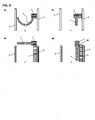
Figure 5a to 5e schematic representations of a passage cycle at the passage lock and -
Figure 6a to 6e further schematic representations of a passage cycle at the passage lock.
Bei einer in
In
In
In den
Ein weiterer wesentlicher Vorteil der erfindungsgemäßen Durchgangsschleuse 1 ist ihr Verhalten im Störungsfall. Dies ist aus den
Die Notfallmeldung kann manuell, automatisch oder auch ferngesteuert ausgelöst werden. Auch bei einem Stromausfall, werden die vorerwähnten erforderlichen Schritte zur Freigabe der Passage ausgelöst. Wenn die Notfall-Situation oder der Stromausfall behoben, also vorbei ist, wird der Antriebskäfig 5 mit dem Sperrelement 7 selbsttätig wieder in seine normale Arbeitsstellung zurückgestellt.The emergency message can be triggered manually, automatically or remotely. Even in the event of a power failure, the aforementioned necessary steps to release the passage are triggered. When the emergency situation or the power failure has been resolved, that is to say is over, the
In den
- Gemäß
Figur 5a ist in einem erstenVerfahrensschritt die Durchgangsschleuse 1 geschlossen, die Person erhält Zutritt und die Durchgangsschleuse öffnet; - im zweiten Verfahrensschritt gemäß
Figur 5b öffnet dieDurchgangsschleuse 1 weiter und die Person beginnt die Durchgangsschleuse zu verlassen; - gemäß
Figur 5cDurchgangsschleuse 1 verlassen und dieDurchgangsschleuse 1 schließt gemäßFigur 5d - gemäß
Figur 5e ist dieDurchgangsschleuse 1 geschlossen und die nächste Person erhält Zutritt um im weiteren Verlauf gemäßFigur 5a beim Öffnen der Durchgangsschleuse 1 den Durchgang zu beginnen.
- According to
Figure 5a in a first method step, theaccess lock 1 is closed, the person is granted access and the access lock opens; - in the second step according to
Figure 5b further opens thepassage lock 1 and the person begins to exit the passage lock; - according to
Figure 5c after full opening, the person has thepassage lock 1 leave and thepassage lock 1 closes according toFigure 5d again; - according to
Figure 5e thepassage lock 1 is closed and the next person is granted access in accordance with the further courseFigure 5a when opening thepassage lock 1 to begin the passage.
In den
Gemäß
- Der erste Schritt gemäß
Figur 6a beginnt mit dem Warten vor der geschlossenen Durchgangsschleuse 1; Mit Figur 6b beginnt die Öffnung und Eintritt indie Durchgangsschleuse 1;Bei Figur 6c findet weiteres Öffnen und Beginn des Durchschreitens der Durchgangsschleuse 1 statt;Gemäß Figur 6d wird dieDurchgangsschleuse 1 verlassen, es beginnt das Schließen und- nach
Figur 6e folgt dasSperren der Durchgangsschleuse 1.
According to
- The first step according to
Figure 6a starts waiting in front of theclosed passage lock 1; - With
Figure 6b begins opening and entry intopassage lock 1; - at
Figure 6c further opening and beginning of passing through thepassage lock 1 takes place; - According to
Figure 6d thepassage lock 1 is left, the closing begins and - after
Figure 6e Followed by the locking ofpassage lock 1.
Aus der vorstehenden Beschreibung wird deutlich, dass zumindest in einer Position die Schließ- bzw. Öffnungsbewegung ein Ringsegment auf einer Kreisbahn um die Körperlängsachse der jeweiligen Person beschreibt, die durch die Durchgangsschleuse tritt.It is clear from the above description that, at least in one position, the closing or opening movement describes a ring segment on a circular path around the longitudinal axis of the body of the respective person who is passing through the passage lock.
- 11
- Durchgangsschleusepassage lock
- 22
- Sperr- oder Leitelementblocking or guiding element
- 33
- Sperr- oder Leitelementblocking or guiding element
- 44
- Standsäulepedestal
- 55
- Antriebskäfigdrive cage
- 66
- Innenrauminner space
- 77
- Sperrelementblocking element
- 88th
- Ringsegmentring segment
- 99
- Elektromotorelectric motor
- 1010
- Elektromotorelectric motor
- 1111
- Antriebseinheitdrive unit
- 1212
- Antriebseinheitdrive unit
- 1313
- Reibradfriction wheel
- 1414
- Reibradfriction wheel
- 1515
- Reibradfriction wheel
- 1616
- Reibradfriction wheel
- 1717
-
Kontur des Ringsegments 8
Ring segment contour 8 - 1818
- Gelenkjoint
Claims (14)
Applications Claiming Priority (1)
| Application Number | Priority Date | Filing Date | Title |
|---|---|---|---|
| DE202020005292.2U DE202020005292U1 (en) | 2020-12-22 | 2020-12-22 | Passage lock |
Publications (1)
| Publication Number | Publication Date |
|---|---|
| EP4019733A1 true EP4019733A1 (en) | 2022-06-29 |
Family
ID=74565078
Family Applications (1)
| Application Number | Title | Priority Date | Filing Date |
|---|---|---|---|
| EP21000359.6A Pending EP4019733A1 (en) | 2020-12-22 | 2021-12-17 | Pass-through lock |
Country Status (2)
| Country | Link |
|---|---|
| EP (1) | EP4019733A1 (en) |
| DE (1) | DE202020005292U1 (en) |
Families Citing this family (2)
| Publication number | Priority date | Publication date | Assignee | Title |
|---|---|---|---|---|
| DE202022001993U1 (en) | 2022-09-09 | 2022-11-07 | Koco Motion Gmbh | passage lock |
| DE102022003309A1 (en) | 2022-09-09 | 2024-03-14 | Koco Motion Gmbh | Passage lock |
Citations (10)
| Publication number | Priority date | Publication date | Assignee | Title |
|---|---|---|---|---|
| NL9201749A (en) | 1991-12-20 | 1993-07-16 | Nedap Nv | Automatic access control to bicycle sheds |
| EP0643189A1 (en) | 1993-09-13 | 1995-03-15 | Wanzl GmbH & Co. Entwicklungs-KG | Pivoting door for passage way for persons |
| DE19612328A1 (en) | 1996-03-28 | 1997-10-02 | Wanzl Metallwarenfabrik Kg | Customer-turnstile for self-service shop |
| CA2267394C (en) | 1999-03-26 | 2005-03-08 | John Dennis Mcguire | Access control device for sequential displacement of a plurality of barriers |
| DE202005012659U1 (en) | 2005-08-11 | 2005-10-20 | Magnetic Autocontrol Gmbh | Rotary barrier for controlling the passage of people has a barrier unit to rotate towards a downward-slanted axis of rotation at 45 degrees to the horizontal |
| DE202011051222U1 (en) | 2011-09-06 | 2011-11-02 | Kaba Gallenschütz GmbH | Passage gate, especially for use at airports |
| DE102011012341A1 (en) | 2011-02-24 | 2012-08-30 | Wanzl Metallwarenfabrik Gmbh | Installation for closing a person's handrail |
| EP2957703A1 (en) * | 2014-06-17 | 2015-12-23 | Scheidt & Bachmann GmbH | Passage barrier |
| DE202017000978U1 (en) | 2017-02-23 | 2017-03-08 | Karl Gotschlich Maschinenbau GesmbH | Security gate |
| EP3334888B1 (en) | 2015-08-14 | 2020-07-08 | Hc2 S.R.L. | Passage barrier system |
-
2020
- 2020-12-22 DE DE202020005292.2U patent/DE202020005292U1/en active Active
-
2021
- 2021-12-17 EP EP21000359.6A patent/EP4019733A1/en active Pending
Patent Citations (10)
| Publication number | Priority date | Publication date | Assignee | Title |
|---|---|---|---|---|
| NL9201749A (en) | 1991-12-20 | 1993-07-16 | Nedap Nv | Automatic access control to bicycle sheds |
| EP0643189A1 (en) | 1993-09-13 | 1995-03-15 | Wanzl GmbH & Co. Entwicklungs-KG | Pivoting door for passage way for persons |
| DE19612328A1 (en) | 1996-03-28 | 1997-10-02 | Wanzl Metallwarenfabrik Kg | Customer-turnstile for self-service shop |
| CA2267394C (en) | 1999-03-26 | 2005-03-08 | John Dennis Mcguire | Access control device for sequential displacement of a plurality of barriers |
| DE202005012659U1 (en) | 2005-08-11 | 2005-10-20 | Magnetic Autocontrol Gmbh | Rotary barrier for controlling the passage of people has a barrier unit to rotate towards a downward-slanted axis of rotation at 45 degrees to the horizontal |
| DE102011012341A1 (en) | 2011-02-24 | 2012-08-30 | Wanzl Metallwarenfabrik Gmbh | Installation for closing a person's handrail |
| DE202011051222U1 (en) | 2011-09-06 | 2011-11-02 | Kaba Gallenschütz GmbH | Passage gate, especially for use at airports |
| EP2957703A1 (en) * | 2014-06-17 | 2015-12-23 | Scheidt & Bachmann GmbH | Passage barrier |
| EP3334888B1 (en) | 2015-08-14 | 2020-07-08 | Hc2 S.R.L. | Passage barrier system |
| DE202017000978U1 (en) | 2017-02-23 | 2017-03-08 | Karl Gotschlich Maschinenbau GesmbH | Security gate |
Also Published As
| Publication number | Publication date |
|---|---|
| DE202020005292U1 (en) | 2021-01-21 |
Similar Documents
| Publication | Publication Date | Title |
|---|---|---|
| EP4019733A1 (en) | Pass-through lock | |
| DE202009005241U1 (en) | Passage barrier | |
| DE3135401C2 (en) | Locking device for a door with a one-piece or multi-piece door leaf | |
| EP0715049A1 (en) | Revolving door assembly | |
| EP2275635B1 (en) | Automatic panic door with at least one sliding door leaf | |
| DE3048763C2 (en) | Gate for industrial and warehouse buildings | |
| DE102020007871A1 (en) | passage lock | |
| DE1926990A1 (en) | In particular, people provided with tickets can gain access through a gate | |
| EP1056920A1 (en) | Revolving door with a night closing panel | |
| EP2360343A2 (en) | Sliding window or sliding door with a closing device | |
| DE202011000675U1 (en) | Cabinet, in particular gas bottle cabinet | |
| EP2957703A1 (en) | Passage barrier | |
| DE102016002494B4 (en) | Security gate | |
| CH674544A5 (en) | Sliding door installation with safety opening - has safety hinged support to swing open under pressure | |
| DE102011077631B4 (en) | Automatic sliding door system | |
| EP3447174A1 (en) | Machine casing | |
| WO2024051874A1 (en) | Passage gate | |
| DE202022001993U1 (en) | passage lock | |
| EP3130735B1 (en) | Automatic sliding door with a drive unit and movable door wings | |
| DE102008028598A1 (en) | Insect protection door, has torsion bar accommodated fixedly with vertically running bar sections in fastener, where vertically running bar sections are movable relative to driver or stop during swiveling of airfoil | |
| DE10215478C1 (en) | Carousel rotating door has inner and outer drum walls with rotation of inner drum wall into common access opening position when used in carousel rotating door system | |
| EP0643791B1 (en) | Controlled, multiple-wing access door | |
| EP3421862A1 (en) | Safety fence for one machine assembly | |
| EP2216473A1 (en) | Sliding / folding blinds | |
| EP3153763B1 (en) | Safety switch for monitoring access to an automation system made of a a fixed and movable part |
Legal Events
| Date | Code | Title | Description |
|---|---|---|---|
| PUAI | Public reference made under article 153(3) epc to a published international application that has entered the european phase |
Free format text: ORIGINAL CODE: 0009012 |
|
| STAA | Information on the status of an ep patent application or granted ep patent |
Free format text: STATUS: THE APPLICATION HAS BEEN PUBLISHED |
|
| AK | Designated contracting states |
Kind code of ref document: A1 Designated state(s): AL AT BE BG CH CY CZ DE DK EE ES FI FR GB GR HR HU IE IS IT LI LT LU LV MC MK MT NL NO PL PT RO RS SE SI SK SM TR |
|
| STAA | Information on the status of an ep patent application or granted ep patent |
Free format text: STATUS: REQUEST FOR EXAMINATION WAS MADE |
|
| 17P | Request for examination filed |
Effective date: 20221125 |
|
| RBV | Designated contracting states (corrected) |
Designated state(s): AL AT BE BG CH CY CZ DE DK EE ES FI FR GB GR HR HU IE IS IT LI LT LU LV MC MK MT NL NO PL PT RO RS SE SI SK SM TR |