EP4015945B1 - Kühlmittelleckbestimmungssystem - Google Patents
Kühlmittelleckbestimmungssystem Download PDFInfo
- Publication number
- EP4015945B1 EP4015945B1 EP20862184.7A EP20862184A EP4015945B1 EP 4015945 B1 EP4015945 B1 EP 4015945B1 EP 20862184 A EP20862184 A EP 20862184A EP 4015945 B1 EP4015945 B1 EP 4015945B1
- Authority
- EP
- European Patent Office
- Prior art keywords
- refrigerant
- determination unit
- subcooling
- leaked
- indoor
- Prior art date
- Legal status (The legal status is an assumption and is not a legal conclusion. Google has not performed a legal analysis and makes no representation as to the accuracy of the status listed.)
- Active
Links
Images



Classifications
-
- F—MECHANICAL ENGINEERING; LIGHTING; HEATING; WEAPONS; BLASTING
- F25—REFRIGERATION OR COOLING; COMBINED HEATING AND REFRIGERATION SYSTEMS; HEAT PUMP SYSTEMS; MANUFACTURE OR STORAGE OF ICE; LIQUEFACTION SOLIDIFICATION OF GASES
- F25B—REFRIGERATION MACHINES, PLANTS OR SYSTEMS; COMBINED HEATING AND REFRIGERATION SYSTEMS; HEAT PUMP SYSTEMS
- F25B49/00—Arrangement or mounting of control or safety devices
- F25B49/02—Arrangement or mounting of control or safety devices for compression type machines, plants or systems
-
- F—MECHANICAL ENGINEERING; LIGHTING; HEATING; WEAPONS; BLASTING
- F24—HEATING; RANGES; VENTILATING
- F24F—AIR-CONDITIONING; AIR-HUMIDIFICATION; VENTILATION; USE OF AIR CURRENTS FOR SCREENING
- F24F11/00—Control or safety arrangements
- F24F11/30—Control or safety arrangements for purposes related to the operation of the system, e.g. for safety or monitoring
- F24F11/32—Responding to malfunctions or emergencies
- F24F11/38—Failure diagnosis
-
- F—MECHANICAL ENGINEERING; LIGHTING; HEATING; WEAPONS; BLASTING
- F24—HEATING; RANGES; VENTILATING
- F24F—AIR-CONDITIONING; AIR-HUMIDIFICATION; VENTILATION; USE OF AIR CURRENTS FOR SCREENING
- F24F11/00—Control or safety arrangements
- F24F11/30—Control or safety arrangements for purposes related to the operation of the system, e.g. for safety or monitoring
- F24F11/49—Control or safety arrangements for purposes related to the operation of the system, e.g. for safety or monitoring ensuring correct operation, e.g. by trial operation or configuration checks
-
- F—MECHANICAL ENGINEERING; LIGHTING; HEATING; WEAPONS; BLASTING
- F24—HEATING; RANGES; VENTILATING
- F24F—AIR-CONDITIONING; AIR-HUMIDIFICATION; VENTILATION; USE OF AIR CURRENTS FOR SCREENING
- F24F11/00—Control or safety arrangements
- F24F11/50—Control or safety arrangements characterised by user interfaces or communication
- F24F11/54—Control or safety arrangements characterised by user interfaces or communication using one central controller connected to several sub-controllers
-
- F—MECHANICAL ENGINEERING; LIGHTING; HEATING; WEAPONS; BLASTING
- F24—HEATING; RANGES; VENTILATING
- F24F—AIR-CONDITIONING; AIR-HUMIDIFICATION; VENTILATION; USE OF AIR CURRENTS FOR SCREENING
- F24F11/00—Control or safety arrangements
- F24F11/62—Control or safety arrangements characterised by the type of control or by internal processing, e.g. using fuzzy logic, adaptive control or estimation of values
- F24F11/63—Electronic processing
- F24F11/64—Electronic processing using pre-stored data
-
- F—MECHANICAL ENGINEERING; LIGHTING; HEATING; WEAPONS; BLASTING
- F24—HEATING; RANGES; VENTILATING
- F24F—AIR-CONDITIONING; AIR-HUMIDIFICATION; VENTILATION; USE OF AIR CURRENTS FOR SCREENING
- F24F11/00—Control or safety arrangements
- F24F11/70—Control systems characterised by their outputs; Constructional details thereof
- F24F11/80—Control systems characterised by their outputs; Constructional details thereof for controlling the temperature of the supplied air
- F24F11/83—Control systems characterised by their outputs; Constructional details thereof for controlling the temperature of the supplied air by controlling the supply of heat-exchange fluids to heat-exchangers
- F24F11/84—Control systems characterised by their outputs; Constructional details thereof for controlling the temperature of the supplied air by controlling the supply of heat-exchange fluids to heat-exchangers using valves
-
- F—MECHANICAL ENGINEERING; LIGHTING; HEATING; WEAPONS; BLASTING
- F25—REFRIGERATION OR COOLING; COMBINED HEATING AND REFRIGERATION SYSTEMS; HEAT PUMP SYSTEMS; MANUFACTURE OR STORAGE OF ICE; LIQUEFACTION SOLIDIFICATION OF GASES
- F25B—REFRIGERATION MACHINES, PLANTS OR SYSTEMS; COMBINED HEATING AND REFRIGERATION SYSTEMS; HEAT PUMP SYSTEMS
- F25B40/00—Subcoolers, desuperheaters or superheaters
-
- F—MECHANICAL ENGINEERING; LIGHTING; HEATING; WEAPONS; BLASTING
- F25—REFRIGERATION OR COOLING; COMBINED HEATING AND REFRIGERATION SYSTEMS; HEAT PUMP SYSTEMS; MANUFACTURE OR STORAGE OF ICE; LIQUEFACTION SOLIDIFICATION OF GASES
- F25B—REFRIGERATION MACHINES, PLANTS OR SYSTEMS; COMBINED HEATING AND REFRIGERATION SYSTEMS; HEAT PUMP SYSTEMS
- F25B43/00—Arrangements for separating or purifying gases or liquids; Arrangements for vaporising the residuum of liquid refrigerant, e.g. by heat
- F25B43/006—Accumulators
-
- F—MECHANICAL ENGINEERING; LIGHTING; HEATING; WEAPONS; BLASTING
- F25—REFRIGERATION OR COOLING; COMBINED HEATING AND REFRIGERATION SYSTEMS; HEAT PUMP SYSTEMS; MANUFACTURE OR STORAGE OF ICE; LIQUEFACTION SOLIDIFICATION OF GASES
- F25B—REFRIGERATION MACHINES, PLANTS OR SYSTEMS; COMBINED HEATING AND REFRIGERATION SYSTEMS; HEAT PUMP SYSTEMS
- F25B49/00—Arrangement or mounting of control or safety devices
- F25B49/005—Arrangement or mounting of control or safety devices of safety devices
-
- F—MECHANICAL ENGINEERING; LIGHTING; HEATING; WEAPONS; BLASTING
- F24—HEATING; RANGES; VENTILATING
- F24F—AIR-CONDITIONING; AIR-HUMIDIFICATION; VENTILATION; USE OF AIR CURRENTS FOR SCREENING
- F24F11/00—Control or safety arrangements
- F24F11/30—Control or safety arrangements for purposes related to the operation of the system, e.g. for safety or monitoring
- F24F11/32—Responding to malfunctions or emergencies
- F24F11/36—Responding to malfunctions or emergencies to leakage of heat-exchange fluid
-
- F—MECHANICAL ENGINEERING; LIGHTING; HEATING; WEAPONS; BLASTING
- F24—HEATING; RANGES; VENTILATING
- F24F—AIR-CONDITIONING; AIR-HUMIDIFICATION; VENTILATION; USE OF AIR CURRENTS FOR SCREENING
- F24F2140/00—Control inputs relating to system states
- F24F2140/10—Pressure
- F24F2140/12—Heat-exchange fluid pressure
-
- F—MECHANICAL ENGINEERING; LIGHTING; HEATING; WEAPONS; BLASTING
- F24—HEATING; RANGES; VENTILATING
- F24F—AIR-CONDITIONING; AIR-HUMIDIFICATION; VENTILATION; USE OF AIR CURRENTS FOR SCREENING
- F24F2140/00—Control inputs relating to system states
- F24F2140/20—Heat-exchange fluid temperature
-
- F—MECHANICAL ENGINEERING; LIGHTING; HEATING; WEAPONS; BLASTING
- F25—REFRIGERATION OR COOLING; COMBINED HEATING AND REFRIGERATION SYSTEMS; HEAT PUMP SYSTEMS; MANUFACTURE OR STORAGE OF ICE; LIQUEFACTION SOLIDIFICATION OF GASES
- F25B—REFRIGERATION MACHINES, PLANTS OR SYSTEMS; COMBINED HEATING AND REFRIGERATION SYSTEMS; HEAT PUMP SYSTEMS
- F25B13/00—Compression machines, plants or systems, with reversible cycle
-
- F—MECHANICAL ENGINEERING; LIGHTING; HEATING; WEAPONS; BLASTING
- F25—REFRIGERATION OR COOLING; COMBINED HEATING AND REFRIGERATION SYSTEMS; HEAT PUMP SYSTEMS; MANUFACTURE OR STORAGE OF ICE; LIQUEFACTION SOLIDIFICATION OF GASES
- F25B—REFRIGERATION MACHINES, PLANTS OR SYSTEMS; COMBINED HEATING AND REFRIGERATION SYSTEMS; HEAT PUMP SYSTEMS
- F25B2313/00—Compression machines, plants or systems with reversible cycle not otherwise provided for
- F25B2313/023—Compression machines, plants or systems with reversible cycle not otherwise provided for using multiple indoor units
- F25B2313/0233—Compression machines, plants or systems with reversible cycle not otherwise provided for using multiple indoor units in parallel arrangements
-
- F—MECHANICAL ENGINEERING; LIGHTING; HEATING; WEAPONS; BLASTING
- F25—REFRIGERATION OR COOLING; COMBINED HEATING AND REFRIGERATION SYSTEMS; HEAT PUMP SYSTEMS; MANUFACTURE OR STORAGE OF ICE; LIQUEFACTION SOLIDIFICATION OF GASES
- F25B—REFRIGERATION MACHINES, PLANTS OR SYSTEMS; COMBINED HEATING AND REFRIGERATION SYSTEMS; HEAT PUMP SYSTEMS
- F25B2400/00—Component parts or details not otherwise provided for in this subclass
- F25B2400/13—Economisers
-
- F—MECHANICAL ENGINEERING; LIGHTING; HEATING; WEAPONS; BLASTING
- F25—REFRIGERATION OR COOLING; COMBINED HEATING AND REFRIGERATION SYSTEMS; HEAT PUMP SYSTEMS; MANUFACTURE OR STORAGE OF ICE; LIQUEFACTION SOLIDIFICATION OF GASES
- F25B—REFRIGERATION MACHINES, PLANTS OR SYSTEMS; COMBINED HEATING AND REFRIGERATION SYSTEMS; HEAT PUMP SYSTEMS
- F25B2400/00—Component parts or details not otherwise provided for in this subclass
- F25B2400/23—Separators
-
- F—MECHANICAL ENGINEERING; LIGHTING; HEATING; WEAPONS; BLASTING
- F25—REFRIGERATION OR COOLING; COMBINED HEATING AND REFRIGERATION SYSTEMS; HEAT PUMP SYSTEMS; MANUFACTURE OR STORAGE OF ICE; LIQUEFACTION SOLIDIFICATION OF GASES
- F25B—REFRIGERATION MACHINES, PLANTS OR SYSTEMS; COMBINED HEATING AND REFRIGERATION SYSTEMS; HEAT PUMP SYSTEMS
- F25B2500/00—Problems to be solved
- F25B2500/22—Preventing, detecting or repairing leaks of refrigeration fluids
- F25B2500/222—Detecting refrigerant leaks
-
- F—MECHANICAL ENGINEERING; LIGHTING; HEATING; WEAPONS; BLASTING
- F25—REFRIGERATION OR COOLING; COMBINED HEATING AND REFRIGERATION SYSTEMS; HEAT PUMP SYSTEMS; MANUFACTURE OR STORAGE OF ICE; LIQUEFACTION SOLIDIFICATION OF GASES
- F25B—REFRIGERATION MACHINES, PLANTS OR SYSTEMS; COMBINED HEATING AND REFRIGERATION SYSTEMS; HEAT PUMP SYSTEMS
- F25B2700/00—Sensing or detecting of parameters; Sensors therefor
- F25B2700/04—Refrigerant level
-
- F—MECHANICAL ENGINEERING; LIGHTING; HEATING; WEAPONS; BLASTING
- F25—REFRIGERATION OR COOLING; COMBINED HEATING AND REFRIGERATION SYSTEMS; HEAT PUMP SYSTEMS; MANUFACTURE OR STORAGE OF ICE; LIQUEFACTION SOLIDIFICATION OF GASES
- F25B—REFRIGERATION MACHINES, PLANTS OR SYSTEMS; COMBINED HEATING AND REFRIGERATION SYSTEMS; HEAT PUMP SYSTEMS
- F25B2700/00—Sensing or detecting of parameters; Sensors therefor
- F25B2700/19—Pressures
- F25B2700/193—Pressures of the compressor
- F25B2700/1931—Discharge pressures
-
- F—MECHANICAL ENGINEERING; LIGHTING; HEATING; WEAPONS; BLASTING
- F25—REFRIGERATION OR COOLING; COMBINED HEATING AND REFRIGERATION SYSTEMS; HEAT PUMP SYSTEMS; MANUFACTURE OR STORAGE OF ICE; LIQUEFACTION SOLIDIFICATION OF GASES
- F25B—REFRIGERATION MACHINES, PLANTS OR SYSTEMS; COMBINED HEATING AND REFRIGERATION SYSTEMS; HEAT PUMP SYSTEMS
- F25B2700/00—Sensing or detecting of parameters; Sensors therefor
- F25B2700/21—Temperatures
- F25B2700/2106—Temperatures of fresh outdoor air
-
- F—MECHANICAL ENGINEERING; LIGHTING; HEATING; WEAPONS; BLASTING
- F25—REFRIGERATION OR COOLING; COMBINED HEATING AND REFRIGERATION SYSTEMS; HEAT PUMP SYSTEMS; MANUFACTURE OR STORAGE OF ICE; LIQUEFACTION SOLIDIFICATION OF GASES
- F25B—REFRIGERATION MACHINES, PLANTS OR SYSTEMS; COMBINED HEATING AND REFRIGERATION SYSTEMS; HEAT PUMP SYSTEMS
- F25B2700/00—Sensing or detecting of parameters; Sensors therefor
- F25B2700/21—Temperatures
- F25B2700/2115—Temperatures of a compressor or the drive means therefor
- F25B2700/21151—Temperatures of a compressor or the drive means therefor at the suction side of the compressor
-
- F—MECHANICAL ENGINEERING; LIGHTING; HEATING; WEAPONS; BLASTING
- F25—REFRIGERATION OR COOLING; COMBINED HEATING AND REFRIGERATION SYSTEMS; HEAT PUMP SYSTEMS; MANUFACTURE OR STORAGE OF ICE; LIQUEFACTION SOLIDIFICATION OF GASES
- F25B—REFRIGERATION MACHINES, PLANTS OR SYSTEMS; COMBINED HEATING AND REFRIGERATION SYSTEMS; HEAT PUMP SYSTEMS
- F25B2700/00—Sensing or detecting of parameters; Sensors therefor
- F25B2700/21—Temperatures
- F25B2700/2115—Temperatures of a compressor or the drive means therefor
- F25B2700/21152—Temperatures of a compressor or the drive means therefor at the discharge side of the compressor
-
- F—MECHANICAL ENGINEERING; LIGHTING; HEATING; WEAPONS; BLASTING
- F25—REFRIGERATION OR COOLING; COMBINED HEATING AND REFRIGERATION SYSTEMS; HEAT PUMP SYSTEMS; MANUFACTURE OR STORAGE OF ICE; LIQUEFACTION SOLIDIFICATION OF GASES
- F25B—REFRIGERATION MACHINES, PLANTS OR SYSTEMS; COMBINED HEATING AND REFRIGERATION SYSTEMS; HEAT PUMP SYSTEMS
- F25B2700/00—Sensing or detecting of parameters; Sensors therefor
- F25B2700/21—Temperatures
- F25B2700/2116—Temperatures of a condenser
-
- F—MECHANICAL ENGINEERING; LIGHTING; HEATING; WEAPONS; BLASTING
- F25—REFRIGERATION OR COOLING; COMBINED HEATING AND REFRIGERATION SYSTEMS; HEAT PUMP SYSTEMS; MANUFACTURE OR STORAGE OF ICE; LIQUEFACTION SOLIDIFICATION OF GASES
- F25B—REFRIGERATION MACHINES, PLANTS OR SYSTEMS; COMBINED HEATING AND REFRIGERATION SYSTEMS; HEAT PUMP SYSTEMS
- F25B2700/00—Sensing or detecting of parameters; Sensors therefor
- F25B2700/21—Temperatures
- F25B2700/2116—Temperatures of a condenser
- F25B2700/21163—Temperatures of a condenser of the refrigerant at the outlet of the condenser
-
- F—MECHANICAL ENGINEERING; LIGHTING; HEATING; WEAPONS; BLASTING
- F25—REFRIGERATION OR COOLING; COMBINED HEATING AND REFRIGERATION SYSTEMS; HEAT PUMP SYSTEMS; MANUFACTURE OR STORAGE OF ICE; LIQUEFACTION SOLIDIFICATION OF GASES
- F25B—REFRIGERATION MACHINES, PLANTS OR SYSTEMS; COMBINED HEATING AND REFRIGERATION SYSTEMS; HEAT PUMP SYSTEMS
- F25B2700/00—Sensing or detecting of parameters; Sensors therefor
- F25B2700/21—Temperatures
- F25B2700/2117—Temperatures of an evaporator
- F25B2700/21174—Temperatures of an evaporator of the refrigerant at the inlet of the evaporator
-
- F—MECHANICAL ENGINEERING; LIGHTING; HEATING; WEAPONS; BLASTING
- F25—REFRIGERATION OR COOLING; COMBINED HEATING AND REFRIGERATION SYSTEMS; HEAT PUMP SYSTEMS; MANUFACTURE OR STORAGE OF ICE; LIQUEFACTION SOLIDIFICATION OF GASES
- F25B—REFRIGERATION MACHINES, PLANTS OR SYSTEMS; COMBINED HEATING AND REFRIGERATION SYSTEMS; HEAT PUMP SYSTEMS
- F25B2700/00—Sensing or detecting of parameters; Sensors therefor
- F25B2700/21—Temperatures
- F25B2700/2117—Temperatures of an evaporator
- F25B2700/21175—Temperatures of an evaporator of the refrigerant at the outlet of the evaporator
-
- F—MECHANICAL ENGINEERING; LIGHTING; HEATING; WEAPONS; BLASTING
- F25—REFRIGERATION OR COOLING; COMBINED HEATING AND REFRIGERATION SYSTEMS; HEAT PUMP SYSTEMS; MANUFACTURE OR STORAGE OF ICE; LIQUEFACTION SOLIDIFICATION OF GASES
- F25B—REFRIGERATION MACHINES, PLANTS OR SYSTEMS; COMBINED HEATING AND REFRIGERATION SYSTEMS; HEAT PUMP SYSTEMS
- F25B40/00—Subcoolers, desuperheaters or superheaters
- F25B40/02—Subcoolers
Definitions
- the present invention relates to a refrigerant leakage determination system.
- JP 2010-107187 A discloses a leakage diagnosis apparatus that determines, by using leakage determination means, whether a refrigerant leakage has occurred in a refrigerant circuit, based on a leakage index value calculated by index value calculation means.
- US 2011/0174059 A1 relates to a leakage diagnosis apparatus for diagnosing presence or absence of refrigerant leakage in a refrigerant circuit using the amount of refrigerant exergy loss in a circuit component, and discloses a refrigerant leakage determination system according to the preamble of claim 1.
- the leakage determination means may determine that the refrigerant leakage has occurred although the refrigerant leakage has not actually occurred. This is an erroneous determination.
- a refrigerant leakage determination system includes a refrigerant circuit, a first determination unit, and a second determination unit.
- the refrigerant circuit includes a compressor, a condenser, an expansion mechanism, and an evaporator.
- the first determination unit determines that refrigerant has leaked from the refrigerant circuit, by using a first state amount of refrigerant as a determination index, the first state amount including at least one of an outlet temperature of the condenser, a suction temperature of the compressor, and a discharge temperature of the compressor.
- the second determination unit determines that refrigerant has leaked from the refrigerant circuit, based on information different from the first state amount. A determination result of the first determination unit is verified by using a determination result of the second determination unit.
- the refrigerant leakage determination system even if the first determination unit determines that refrigerant has leaked, it is possible to prevent a determination from being made that refrigerant has leaked when the second determination unit does not determine, based on other information, that refrigerant has leaked.
- an accuracy of a determination result of the first determination unit can be increased by the second determination unit, and an erroneous determination of refrigerant leakage can be reduced.
- a refrigerant leakage determination system is the refrigerant leakage determination system according to the first aspect, in which the first determination unit uses, as the first state amount, a degree of subcooling or a value corresponding to the degree of subcooling, the degree of subcooling being a temperature difference between a condensation temperature of a refrigerant in the condenser and the outlet temperature of the condenser.
- value corresponding to the degree of subcooling includes a value obtained by correcting, with another state amount, a difference in physical property value, such as entropy or enthalpy, and also a difference in degree of subcooling or physical property value, between a refrigerant in a saturation state in the condenser and a refrigerant at an outlet of the condenser.
- a degree of subcooling or a value corresponding to the degree of subcooling is used as a determination index, and thus an accuracy with which the first determination unit detects a refrigerant leakage can be increased.
- a refrigerant leakage determination system is the refrigerant leakage determination system according to the second aspect, in which the value corresponding to the degree of subcooling is a value corrected by a temperature of outdoor air.
- the value corresponding to the degree of subcooling corrected by at least the temperature of outdoor air is used.
- an accuracy of detecting a refrigerant leakage can be increased compared to a case of using the degree of subcooling.
- a refrigerant leakage determination system is the refrigerant leakage determination system according to the first to third aspects, in which the refrigerant leakage determination system further includes a condenser outlet temperature sensor that measures the outlet temperature of the condenser.
- the second determination unit detects, by using a value of the condenser outlet temperature sensor, whether the condenser outlet temperature sensor has a failure, to determine that refrigerant has leaked.
- the second determination unit detects whether the condenser outlet temperature sensor, which is used by the first determination unit to determine that refrigerant has leaked, has a failure.
- the first determination unit determines that refrigerant has leaked, it is possible to prevent a determination from being made that refrigerant has leaked if the second determination unit detects that the condenser outlet temperature sensor has a failure.
- an erroneous determination of a refrigerant leakage can be further reduced.
- a refrigerant leakage determination system is the refrigerant leakage determination system according to the first to fourth aspects, in which the refrigerant leakage determination system further includes a discharge pressure sensor that measures a discharge pressure of the compressor.
- the second determination unit detects, by using a value of the discharge pressure sensor, whether the discharge pressure sensor has a failure, to determine that refrigerant has leaked.
- the second determination unit detects whether the discharge pressure sensor, which is used by the first determination unit to determine that refrigerant has leaked, has a failure.
- the first determination unit determines that refrigerant has leaked, it is possible to prevent a determination from being made that refrigerant has leaked if the second determination unit detects that the discharge pressure sensor has a failure.
- an erroneous determination of a refrigerant leakage can be further reduced.
- a refrigerant leakage determination system is the refrigerant leakage determination system according to the first to fifth aspects, in which the refrigerant leakage determination system further includes an accumulator that stores surplus refrigerant.
- the second determination unit detects, based on a degree of discharge superheating or a value corresponding to the degree of discharge superheating, whether refrigerant remains inside the accumulator, to determine that refrigerant has leaked, the degree of discharge superheating being a difference between the discharge temperature of the compressor and a condensation temperature of a refrigerant in the condenser.
- the second determination unit makes it possible to reduce an erroneous determination of a refrigerant leakage resulting from refrigerant remaining inside the accumulator.
- a refrigerant leakage determination system is the refrigerant leakage determination system according to the sixth aspect, in which in a case where the degree of discharge superheating or the value corresponding to the degree of discharge superheating is smaller than or equal to a threshold value, the second determination unit determines that refrigerant has not leaked.
- the second determination unit makes it possible to reduce an erroneous determination of a refrigerant leakage resulting from the degree of discharge superheating or the value corresponding to the degree of discharge superheating being smaller than or equal to the threshold value.
- a refrigerant leakage determination system is the refrigerant leakage determination system according to the first to seventh aspects, in which the evaporator is an indoor heat exchanger mounted in an indoor unit.
- the refrigerant leakage determination system further includes at least one of an evaporator inlet temperature sensor that measures an inlet temperature of the evaporator and an evaporator outlet temperature sensor that measures an outlet temperature.
- the second determination unit detects, by using a value of at least one of the evaporator inlet temperature sensor and the evaporator outlet temperature sensor, whether at least one of the evaporator inlet temperature sensor and the evaporator outlet temperature sensor has a failure, to determine that refrigerant has leaked.
- the second determination unit makes it possible to reduce an erroneous determination of a refrigerant leakage resulting from refrigerant remaining inside the accumulator, which is caused by a decrease in the value of the evaporator inlet temperature sensor due to a failure and an increase in the value of the evaporator outlet temperature sensor due to a failure.
- a refrigerant leakage determination system is the refrigerant leakage determination system according to the first to eigth aspects, in which the evaporator is an indoor heat exchanger mounted in an indoor unit.
- the expansion mechanism includes an indoor-side expansion valve mounted in the indoor unit.
- the second determination unit detects, by using a degree of superheating at an outlet of the indoor heat exchanger and an opening degree of the indoor-side expansion valve, whether the indoor-side expansion valve has a failure, to determine that refrigerant has leaked, the degree of superheating at the outlet of the indoor heat exchanger being a difference between an outlet temperature of the evaporator and an evaporation temperature of a refrigerant in the evaporator.
- the second determination unit detects whether the indoor-side expansion valve, which is used by the first determination unit to determine that refrigerant has leaked, has a failure.
- the first determination unit determines that refrigerant has leaked, it is possible to prevent a determination from being made that refrigerant has leaked if the second determination unit detects that the indoor-side expansion valve has a failure.
- an erroneous determination of a refrigerant leakage can be further reduced.
- a refrigerant leakage determination system is the refrigerant leakage determination system according to the first to ninth aspects, in which the condenser is an outdoor heat exchanger mounted in an outdoor unit.
- the refrigerant leakage determination system further includes a subcooling heat exchanger disposed at an outlet side of the condenser.
- the second determination unit determines that refrigerant has leaked, based on a state amount of refrigerant passing through the subcooling heat exchanger.
- the second determination unit is capable of grasping a change in the amount of refrigerant, based on a state amount of refrigerant in the subcooling heat exchanger.
- the second determination unit is capable of detecting a refrigerant leakage based on information different from the first state amount, and thus an erroneous determination can be further reduced.
- a refrigerant leakage determination system is the refrigerant leakage determination system according to the tenth aspect, in which the refrigerant leakage determination system further includes a bypass pipe and a subcooling-heat-exchanger outlet temperature sensor.
- the bypass pipe connects the subcooling heat exchanger and the compressor.
- the subcooling-heat-exchanger outlet temperature sensor is disposed at the bypass pipe and measures an outlet temperature of the subcooling heat exchanger.
- the second determination unit detects, by using a value of the subcooling-heat-exchanger outlet temperature sensor, whether the subcooling-heat-exchanger outlet temperature sensor has a failure, to determine that refrigerant has leaked.
- the second determination unit makes it possible to reduce an erroneous determination resulting from a decrease in the discharge temperature of the compressor, which is caused by refrigerant remaining inside the accumulator due a failure of the subcooling-heat-exchanger outlet temperature sensor.
- a refrigerant leakage determination system is the refrigerant leakage determination system according to the tenth or eleventh aspect, in which the refrigerant leakage determination system further includes a bypass pipe and a subcooling-heat-exchanger outlet temperature sensor.
- the bypass pipe connects the subcooling heat exchanger and the compressor.
- the subcooling-heat-exchanger outlet temperature sensor is disposed at the bypass pipe and measures an outlet temperature of the subcooling heat exchanger.
- the expansion mechanism includes a subcooling-heat-exchanger-side expansion valve that decompresses a refrigerant which flows through the bypass pipe and which is to enter the subcooling heat exchanger.
- the second determination unit detects, by using either an outlet temperature of the subcooling heat exchanger or a degree of superheating at an outlet of the subcooling heat exchanger, the degree of superheating at the outlet of the subcooling heat exchanger being a difference between the outlet temperature of the subcooling heat exchanger and an evaporation temperature of a refrigerant in the subcooling heat exchanger, and an opening degree of the subcooling-heat-exchanger-side expansion valve, whether the subcooling-heat-exchanger-side expansion valve has a failure, to determine that refrigerant has leaked.
- the second determination unit makes it possible to reduce an erroneous determination of a refrigerant leakage resulting from refrigerant remaining inside the accumulator, which is caused by a failure of the subcooling-side expansion valve.
- a refrigerant leakage determination system is the refrigerant leakage determination system according to the first to twelfth aspects, in which the evaporator is an indoor heat exchanger mounted in an indoor unit.
- the second determination unit detects dirt of a filter that traps dust in air that is prior to pass through the evaporator, to determine that refrigerant has leaked.
- the second determination unit makes it possible to reduce an erroneous determination resulting from a decrease in the discharge temperature of the compressor, which is caused by refrigerant remaining inside the accumulator due dirt of the filter.
- the external apparatus herein is an apparatus outside an apparatus mainly including the refrigerant circuit.
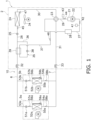
- a refrigerant leakage determination system 1 is a system that determines that refrigerant has leaked from a refrigerant circuit 10.
- the refrigerant leakage determination system 1 includes the refrigerant circuit 10, a first determination unit 60, a second determination unit 70, and a verification unit 80.
- the refrigerant circuit 10 includes a compressor 21, a condenser, an expansion mechanism, and an evaporator.
- the condenser corresponds to an outdoor heat exchanger 24 mounted in an outdoor unit 2 during a cooling operation, and corresponds to indoor heat exchangers 52a and 52b respectively mounted in indoor units 5a and 5b during a heating operation.
- the expansion mechanism includes an outdoor-side expansion valve 25, a subcooling-heat-exchanger-side expansion valve 38, and indoor-side expansion valves 51a and 51b.
- the evaporator corresponds to the indoor heat exchangers 52a and 52b respectively mounted in the indoor units 5a and 5b during a cooling operation, and corresponds to the outdoor heat exchanger 24 mounted in the outdoor unit 2 during a heating operation.
- An air conditioner is constituted mainly by the refrigerant circuit 10.
- the air conditioner includes the outdoor unit 2, the plurality of indoor units 5a and 5b, a liquid-refrigerant connection pipe 6, and a gas-refrigerant connection pipe 7.
- the plurality of (two in Fig. 1 ) indoor units 5a and 5b are connected in parallel to each other.
- a single indoor unit may be provided.
- the liquid-refrigerant connection pipe 6 and the gas-refrigerant connection pipe 7 connect the outdoor unit 2 and the indoor units 5a and 5b to each other.
- the refrigerant circuit 10 is filled with, for example, chlorofluorocarbon-based refrigerant.
- the refrigerant with which the refrigerant circuit 10 of the present disclosure is filled is not particularly limited.
- the indoor units 5a and 5b are installed inside a building or the like.
- the indoor units 5a and 5b are connected to the outdoor unit 2 via the liquid-refrigerant connection pipe 6 and the gas-refrigerant connection pipe 7, and constitute a part of the refrigerant circuit 10.
- the indoor unit 5a and the indoor unit 5b have configurations similar to each other. Thus, only the configuration of the indoor unit 5a will be described here. As for the configuration of the indoor unit 5b, a reference symbol "b" is attached instead of a reference symbol "a” indicating individual components of the indoor unit 5a, and a description of individual components will not be repeated.
- the indoor unit 5a mainly includes the indoor-side expansion valve 51a, the indoor heat exchanger 52a, an indoor liquid-refrigerant pipe 53a, an indoor gas-refrigerant pipe 54a, an indoor fan 55a, and a filter 56a.
- the indoor-side expansion valve 51a is an electric expansion valve that performs adjustment or the like of a flow rate of the refrigerant flowing through the indoor heat exchanger 52a and whose opening degree is adjustable.
- the indoor-side expansion valve 51a is provided in the indoor liquid-refrigerant pipe 53a.
- the indoor heat exchanger 52a performs heat exchange between a refrigerant and indoor air.
- the indoor heat exchanger 52a functions as an evaporator for a refrigerant to cool indoor air during a cooling operation, and functions as a condenser for a refrigerant to heat indoor air during a heating operation.
- the indoor liquid-refrigerant pipe 53a connects a liquid-side end of the indoor heat exchanger 52a and the liquid-refrigerant connection pipe 6.
- the indoor gas-refrigerant pipe 54a connects a gas-side end of the indoor heat exchanger 52a and the gas-refrigerant connection pipe 7.
- the indoor fan 55a sucks indoor air into the indoor unit 5a, causes the indoor air to exchange heat with refrigerant in the indoor heat exchanger 52a, and then supplies the indoor air as supplied air into a room.
- the indoor fan 55a supplies, to the indoor heat exchanger 52a, indoor air serving as a heating source or cooling source of the refrigerant flowing through the indoor heat exchanger 52a.
- the filter 56a is disposed upstream from the indoor heat exchanger 52a.
- the filter 56a traps dust in air that is prior to pass through the indoor heat exchanger 52a.
- the indoor unit 5a is provided with various sensors. Specifically, the indoor unit 5a includes an indoor-heat-exchanger inlet temperature sensor 57a, an indoor-heat-exchanger outlet temperature sensor 58a, and a filter sensor 59a.
- the indoor-heat-exchanger inlet temperature sensor 57a detects a temperature TH2 of a refrigerant at the liquid-side end of the indoor heat exchanger 52a.
- the indoor-heat-exchanger inlet temperature sensor 57a serves as an evaporator inlet temperature sensor that measures an inlet temperature of the evaporator.
- the indoor-heat-exchanger inlet temperature sensor 57a serves as a condenser outlet temperature sensor that measures an outlet temperature of the condenser.
- the indoor-heat-exchanger outlet temperature sensor 58a detects a temperature TH3 of a refrigerant at the gas-side end of the indoor heat exchanger 52a.
- the indoor-heat-exchanger outlet temperature sensor 58a serves as an evaporator outlet temperature sensor that measures an outlet temperature of the evaporator.
- the indoor-heat-exchanger outlet temperature sensor 58a serves as a condenser inlet temperature sensor that measures an inlet temperature of the condenser.
- the filter sensor 59a detects dirt of the filter 56a.
- the filter sensor 59a detects, for example, how much dust has been trapped in the filter 56a.
- the filter sensor 59a is provided in the filter 56a.
- the outdoor unit 2 is installed outside a building or the like.
- the outdoor unit 2 is connected to the indoor units 5a and 5b via the liquid-refrigerant connection pipe 6 and the gas-refrigerant connection pipe 7, and constitutes a part of the refrigerant circuit 10.
- the outdoor unit 2 mainly includes the compressor 21, a switching mechanism 23, the outdoor heat exchanger 24, the outdoor-side expansion valve 25, an outdoor liquid-refrigerant pipe 26, a suction pipe 27, an accumulator 28, a discharge pipe 29, a first outdoor gas-refrigerant pipe 30, a second outdoor gas-refrigerant pipe 31, a liquid-side shutoff valve 32, a gas-side shutoff valve 33, an outdoor fan 34, a bypass pipe 35, the subcooling-heat-exchanger-side expansion valve 38, and a subcooling heat exchanger 39.
- the compressor 21 is a device that compresses low-pressure refrigerant to high-pressure refrigerant.
- a compressor used as the compressor 21 has a hermetic structure in which a positive-displacement compression element (not illustrated), such as a rotary or scroll compression element, is driven to rotate by a compressor motor 22.
- a positive-displacement compression element such as a rotary or scroll compression element
- the number of rotations of the compressor motor 22 can be controlled by an inverter or the like, and accordingly the capacity of the compressor 21 can be controlled.
- the switching mechanism 23 is a four-way switching valve capable of switching a flowing direction of the refrigerant in the refrigerant circuit 10.
- the switching mechanism 23 is a mechanism capable of performing switching, during a cooling operation, to cause a suction side of the compressor 21 to communicate with the gas-refrigerant connection pipe 7 through the suction pipe 27 and the second outdoor gas-refrigerant pipe 31, and cause a discharge side of the compressor 21 to communicate with a gas-side end of the outdoor heat exchanger 24 through the discharge pipe 29 and the first outdoor gas-refrigerant pipe 30.
- the refrigerant circuit 10 is capable of, by switching of the switching mechanism 23, performing switching to a cooling cycle state (see the solid lines in the switching mechanism 23 in Fig.
- the switching mechanism 23 is a mechanism capable of performing switching, during a heating operation, to cause the suction side of the compressor 21 to communicate with the gas-side end of the outdoor heat exchanger 24 through the suction pipe 27 and the first outdoor gas-refrigerant pipe 30, and cause the discharge side of the compressor 21 to communicate with the gas-refrigerant connection pipe 7 through the discharge pipe 29 and the second outdoor gas-refrigerant pipe 31.
- the refrigerant circuit 10 is capable of, by switching of the switching mechanism 23, performing switching to a heating cycle state (see the broken lines in the switching mechanism 23 in Fig. 1 ) in which the outdoor heat exchanger 24 functions as an evaporator for a refrigerant and the indoor heat exchangers 52a and 52b function as a condenser for a refrigerant.
- the switching mechanism 23 is not limited to a four-way switching valve, and may have a configuration in which a plurality of electromagnetic valves and a refrigerant pipe are combined to perform the above-described switching of a flowing direction of the refrigerant.
- the outdoor heat exchanger 24 performs heat exchange between a refrigerant and outdoor air.
- the outdoor heat exchanger 24 functions as a condenser for a refrigerant during a cooling operation, and functions as an evaporator for a refrigerant during a heating operation.
- the outdoor heat exchanger 24 has a liquid-side end connected to the outdoor liquid-refrigerant pipe 26, and a gas-side end connected to the first outdoor gas-refrigerant pipe 30.
- the outdoor-side expansion valve 25 is an electric expansion valve that performs adjustment or the like of a flow rate of the refrigerant flowing through the outdoor heat exchanger 24 and whose opening degree is adjustable.
- the outdoor-side expansion valve 25 is provided in the outdoor liquid-refrigerant pipe 26.
- the outdoor liquid-refrigerant pipe 26 connects the liquid-side end of the outdoor heat exchanger 24 and the liquid-refrigerant connection pipe 6.
- the suction pipe 27 connects the switching mechanism 23 and the suction side of the compressor 21.
- the suction pipe 27 is provided with the accumulator 28 that temporarily stores refrigerant that is to be sucked by the compressor 21. In other words, the accumulator 28 stores surplus refrigerant.
- the discharge pipe 29 connects the discharge side of the compressor 21 and the switching mechanism 23.
- the first outdoor gas-refrigerant pipe 30 connects the switching mechanism 23 and the gas-side end of the outdoor heat exchanger 24.
- the second outdoor gas-refrigerant pipe 31 connects the gas-refrigerant connection pipe 7 and the switching mechanism 23.
- the liquid-side shutoff valve 32 is provided at a connection portion between the outdoor liquid-refrigerant pipe 26 and the liquid-refrigerant connection pipe 6.
- the gas-side shutoff valve 33 is provided at a connection portion between the second outdoor gas-refrigerant pipe 31 and the gas-refrigerant connection pipe 7.
- the liquid-side shutoff valve 32 and the gas-side shutoff valve 33 are valves that are opened or closed manually.
- the outdoor fan 34 sucks outdoor air into the outdoor unit 2, causes the outdoor air to exchange heat with a refrigerant in the outdoor heat exchanger 24, and then discharges the outdoor air to the outside of the outdoor unit 2.
- the outdoor fan 34 supplies, to the outdoor heat exchanger 24, outdoor air serving as a cooling source or heating source of the refrigerant flowing through the outdoor heat exchanger 24.
- the outdoor liquid-refrigerant pipe 26 is connected to the bypass pipe 35 and is provided with the subcooling heat exchanger 39.
- the bypass pipe 35 is a refrigerant pipe that causes a part of the refrigerant flowing through the outdoor liquid-refrigerant pipe 26 to branch off and return to the compressor 21.
- the subcooling heat exchanger 39 cools the refrigerant flowing through the outdoor liquid-refrigerant pipe 26 by using low-pressure the refrigerant flowing through the bypass pipe 35.
- the subcooling heat exchanger 39 is provided, in the outdoor liquid-refrigerant pipe 26, between the outdoor-side expansion valve 25 and the liquid-side shutoff valve 32.
- the bypass pipe 35 connects the subcooling heat exchanger 39 and the compressor 21.
- the bypass pipe 35 is a refrigerant return pipe that sends the refrigerant branched from the outdoor liquid-refrigerant pipe 26 to the suction side of the compressor 21.
- the bypass pipe 35 includes a refrigerant return inlet pipe 36 and a refrigerant return outlet pipe 37.
- the refrigerant return inlet pipe 36 is a refrigerant pipe that causes a part of the refrigerant flowing through the outdoor liquid-refrigerant pipe 26 to branch off and sends the part of the refrigerant to an inlet on the bypass pipe 35 side of the subcooling heat exchanger 39.
- the refrigerant return inlet pipe 36 is connected to the outdoor-side expansion valve 25 and the subcooling heat exchanger 39.
- the refrigerant return inlet pipe 36 is provided with the subcooling-heat-exchanger-side expansion valve 38 that performs adjustment or the like of a flow rate of the refrigerant flowing through the bypass pipe 35.
- the subcooling-heat-exchanger-side expansion valve 38 decompresses the refrigerant that flows through the bypass pipe 35 and that is to enter the subcooling heat exchanger 39.
- the subcooling-heat-exchanger-side expansion valve 38 is an electric expansion valve.
- the refrigerant return outlet pipe 37 is a refrigerant pipe that sends the refrigerant from an outlet on the bypass pipe 35 side of the subcooling heat exchanger 39 to the suction pipe 27 connected to the suction side of the compressor 21.
- the bypass pipe 35 may be a refrigerant pipe that sends the refrigerant to a point in a compression process of the compressor 21, not to the suction side of the compressor 21.
- the suction pressure sensor 41 detects a suction pressure Lp of the compressor 21.
- the suction temperature sensor 42 detects a suction temperature Ts of the compressor 21.
- the discharge pressure sensor 43 detects a discharge pressure Hp of the compressor 21.
- the discharge temperature sensor 44 detects a discharge temperature Td of the compressor 21.
- the outdoor-heat-exchanger outlet temperature sensor 45 is provided, in the outdoor liquid-refrigerant pipe 26, closer to the outdoor heat exchanger 24 than to the subcooling heat exchanger 39 (in Fig. 1 , closer to the outdoor heat exchanger 24 than to the outdoor-side expansion valve 25).
- the outdoor-heat-exchanger outlet temperature sensor 45 detects a temperature Tb of a refrigerant at the liquid-side end of the outdoor heat exchanger 24.
- the outdoor-heat-exchanger outlet temperature sensor 45 serves as a condenser outlet temperature sensor that measures an outlet temperature Tb of the condenser.
- the outdoor-heat-exchanger outlet temperature sensor 45 serves as an evaporator inlet temperature sensor that measures an inlet temperature of the evaporator.
- the subcooling-heat-exchanger outlet temperature sensor 46 is provided in the refrigerant return outlet pipe 37.
- the subcooling-heat-exchanger outlet temperature sensor 46 measures an outlet temperature Tsh of the subcooling heat exchanger 39. Specifically, the subcooling-heat-exchanger outlet temperature sensor 46 detects a temperature Tsh of a refrigerant flowing through the outlet on the bypass pipe 35 side of the subcooling heat exchanger 39.
- the outdoor temperature sensor 47 is provided around the outdoor heat exchanger 24 and the outdoor fan 34.
- the outdoor temperature sensor 47 measures a temperature Ta of outdoor air to be sucked into the outdoor heat exchanger 24.
- the liquid-refrigerant connection pipe 6 and the gas-refrigerant connection pipe 7 are refrigerant pipes that are installed on a site when the air conditioner including the refrigerant circuit 10 is installed in an installation place, such as a building, and the lengths or pipe diameters thereof vary according to an installation condition, such as an installation place or a combination of the outdoor unit 2 and the indoor units 5a and 5b.
- the refrigerant flowing through the liquid-refrigerant connection pipe 6 may be liquid or may have two phases of gas and liquid.
- the first determination unit 60 determines that refrigerant has leaked from the refrigerant circuit 10, by using a first state amount of refrigerant as a determination index.
- the first state amount includes at least an outlet temperature of a condenser, a suction temperature of the compressor 21, or a discharge temperature of the compressor 21.
- a degree of subcooling (SC), a degree of suction superheating (suction SH), a degree of discharge superheating (DSH), and a value corresponding thereto can be used.
- the degree of subcooling is a temperature difference between a condensation temperature Tc and an outlet temperature Tb of a refrigerant in the condenser, and is expressed by Tc - Tb.
- a value corresponding to the degree of subcooling (hereinafter also referred to as an "SC corresponding value") is, for example, (Tc - Tb)/(Tc - Ta).
- the SC corresponding value herein is not limited to the value expressed by the above expression, and may be a value corrected by another parameter.
- the SC corresponding value includes a value corrected by a frequency of the compressor, a value corrected in consideration of a physical property value, a value corrected through conversion into a Mollier diagram, and the like.
- the second determination unit 70 detects, by using a value of the discharge pressure sensor 43, whether the discharge pressure sensor 43 has a failure, thereby determining that refrigerant has leaked.
- the discharge pressure sensor 43 has a failure and outputs a value of the discharge pressure Hp of the compressor 21 smaller than a true value
- a condensation temperature Tc that is calculated decreases in the first determination unit 60, and thus the degree of subcooling and the SC corresponding value are smaller than the reference value.
- the first determination unit 60 determines that refrigerant has leaked.
- the second determination unit 70 determines that refrigerant has not leaked, in response to detecting that the discharge pressure sensor 43 has a failure.
- the verification unit 80 determines that the determination result of the first determination unit 60 is wrong and determines that refrigerant has not leaked from the refrigerant circuit 10.
- the verification unit 80 determines that refrigerant has leaked. In this case, the verification unit 80 determines that the determination result of the first determination unit 60 is correct and determines that refrigerant has leaked from the refrigerant circuit 10.
- the second determination unit 70 detects, based on a degree of discharge superheating or a DSH corresponding value, whether refrigerant remains inside the accumulator 28, thereby determining that refrigerant has leaked.
- the second determination unit 70 detects whether a wet operation is being performed in which the degree of discharge superheating or the DSH corresponding value is smaller than or equal to a normal value, and detects whether an erroneous determination has been made due to refrigerant remaining inside the accumulator 28 because of a wet operation.
- a decrease in the inlet temperature TH2 of the evaporator output from the evaporator inlet temperature sensor (indoor-heat-exchanger inlet temperature sensors 57a and 57b) or an increase in the outlet temperature TH3 of the evaporator output from the evaporator outlet temperature sensor (indoor-heat-exchanger outlet temperature sensors 58a and 58b) causes the degree of superheating at the evaporator outlet to be higher than a reference value. Accordingly, to overcome excessive superheating, the opening degrees of the indoor-side expansion valves 51a and 51b are wrongly controlled to be increased. As a result, a circulation amount of refrigerant increases, and refrigerant that failed to evaporate remains inside the accumulator 28.
- the first determination unit 60 determines that refrigerant has leaked. At this time, the wetness of the refrigerant sucked by the compressor 21 is high. Thus, a wet operation is performed, and the degree of discharge superheating or the DSH corresponding value decreases.
- the second determination unit 70 detects, based on the degree of discharge superheating or the DSH corresponding value, the refrigerant remaining inside the accumulator 28, and utilizes the detection for determination.
- the second determination unit 70 determines that a wet operation is being performed and refrigerant has not leaked.
- the threshold value is, for example, 20°C, and is preferably 15°C.
- the second determination unit 70 detects, by using a value of an evaporator inlet temperature sensor (indoor-heat-exchanger inlet temperature sensors 57a and 57b), whether the evaporator inlet temperature sensor has a failure, thereby determining that refrigerant has leaked.
- an evaporator inlet temperature sensor indoor-heat-exchanger inlet temperature sensors 57a and 57b
- the evaporator inlet temperature sensor has a failure and outputs a value of the inlet temperature TH2 of the evaporator smaller than a true value
- the degree of superheating at the evaporator outlet becomes higher than a reference value. Accordingly, to overcome excessive superheating, the opening degree of the indoor-side expansion valve is wrongly controlled to be increased.
- the first determination unit 60 determines that refrigerant has leaked.
- the second determination unit 70 determines that refrigerant has not leaked, in response to detecting that the evaporator inlet temperature sensor has a failure.
- the verification unit 80 that has received determination results of the first determination unit 60 and the second determination unit 70 determines that the determination result of the first determination unit 60 is wrong and determines that refrigerant has not leaked.
- the second determination unit 70 determines that refrigerant has leaked, in response to detecting that the evaporator inlet temperature sensor does not have a failure.
- the verification unit 80 determines that the determination result of the first determination unit 60 is correct and determines that refrigerant has leaked from the refrigerant circuit 10.
- the second determination unit 70 detects, by using a value of an evaporator outlet temperature sensor (indoor-heat-exchanger outlet temperature sensors 58a and 58b), whether the evaporator outlet temperature sensor has a failure, thereby determining that refrigerant has leaked.
- an evaporator outlet temperature sensor indoor-heat-exchanger outlet temperature sensors 58a and 58b
- the evaporator outlet temperature sensor has a failure and outputs a value of the outlet temperature TH3 of the evaporator greater than a true value
- the degree of superheating at the evaporator outlet becomes higher than a reference value. Accordingly, to overcome excessive superheating, the opening degree of the indoor-side expansion valve is wrongly controlled to be increased.
- the first determination unit 60 determines that refrigerant has leaked.
- the second determination unit 70 determines that refrigerant has not leaked, in response to detecting that the evaporator outlet temperature sensor has a failure.
- the verification unit 80 determines that the determination result of the first determination unit 60 is wrong and determines that refrigerant has not leaked.
- the second determination unit 70 determines that refrigerant has leaked, in response to detecting that the evaporator outlet temperature sensor does not have a failure.
- the verification unit 80 determines that the determination result of the first determination unit 60 is correct and determines that refrigerant has leaked from the refrigerant circuit 10.
- the second determination unit 70 detects, by using a value of the evaporator inlet temperature sensor (indoor-heat-exchanger inlet temperature sensors 57a and 57b), whether the evaporator outlet temperature sensor (indoor-heat-exchanger outlet temperature sensors 58a and 58b) has a failure, thereby determining that refrigerant has leaked.
- the second determination unit 70 detects, by using a value of the evaporator outlet temperature sensor (indoor-heat-exchanger outlet temperature sensors 58a and 58b), whether the evaporator inlet temperature sensor (indoor-heat-exchanger inlet temperature sensors 57a and 57b) has a failure.
- the second determination unit 70 detects, by using values of the evaporator inlet temperature sensor (indoor-heat-exchanger inlet temperature sensors 57a and 57b) and the evaporator outlet temperature sensor (indoor-heat-exchanger outlet temperature sensors 58a and 58b), whether the evaporator inlet temperature sensor (indoor-heat-exchanger inlet temperature sensors 57a and 57b) and the evaporator outlet temperature sensor (indoor-heat-exchanger outlet temperature sensors 58a and 58b) have a failure.
- the second determination unit 70 detects, by using a degree of superheating at the outlet of the indoor heat exchanger, which is a difference between outlet temperatures of the indoor heat exchangers 52a and 52b and evaporation temperatures of the refrigerant in the indoor heat exchangers 52a and 52b, and values of the opening degrees of the indoor-side expansion valves 51a and 51b, whether the indoor-side expansion valves 51a and 51b have a failure, thereby determining that refrigerant has leaked.
- a degree of superheating at the outlet of the indoor heat exchanger which is a difference between outlet temperatures of the indoor heat exchangers 52a and 52b and evaporation temperatures of the refrigerant in the indoor heat exchangers 52a and 52b
- values of the opening degrees of the indoor-side expansion valves 51a and 51b whether the indoor-side expansion valves 51a and 51b have a failure, thereby determining that refrigerant has leaked.
- the second determination unit 70 detects whether the indoor-side expansion valves 51a and 51b have a failure, by using the degree of superheating at the outlet of the indoor heat exchanger and the opening degree instruction value of the indoor-side expansion valves 51a and 51b. In response to detecting that the indoor-side expansion valves 51a and 51b have a failure, the second determination unit 70 determines that refrigerant has not leaked. In this case, the verification unit 80 determines that the determination result of the first determination unit 60 is wrong and determines that refrigerant has not leaked. On the other hand, in response to detecting that the indoor-side expansion valves 51a and 51b do not have a failure, the second determination unit 70 determines that refrigerant has leaked. In this case, the verification unit 80 determines that the determination result of the first determination unit 60 is correct and determines that refrigerant has leaked from the refrigerant circuit 10.
- the second determination unit 70 determines that refrigerant has leaked, based on a state amount of refrigerant that passes through the subcooling heat exchanger 39.
- the opening degree of the subcooling-heat-exchanger-side expansion valve 38 is controlled to increase. Otherwise, a mechanical failure may occur in the subcooling-heat-exchanger-side expansion valve 38, and the opening degree of the subcooling-heat-exchanger-side expansion valve 38 may be fixed to a large value.
- the first determination unit 60 determines that refrigerant has leaked. At this time, the wetness of the refrigerant sucked by the compressor 21 is high. Thus, a wet operation is performed, and the degree of discharge superheating or the DSH corresponding value decreases.
- the second determination unit 70 makes a determination by using a state amount of refrigerant in the subcooling heat exchanger 39.
- the second determination unit 70 determines that refrigerant has not leaked. In this case, the verification unit 80 determines that the determination result of the first determination unit 60 is wrong and determines that refrigerant has not leaked.
- the second determination unit 70 determines that refrigerant has leaked. In this case, the verification unit 80 determines that the determination result of the first determination unit 60 is correct and determines that refrigerant has leaked from the refrigerant circuit 10.
- the second determination unit 70 detects, by using a value of the subcooling-heat-exchanger outlet temperature sensor 46, whether the subcooling-heat-exchanger outlet temperature sensor 46 has a failure, thereby determining that refrigerant has leaked.
- the opening degree of the subcooling-heat-exchanger-side expansion valve 38 is controlled to increase, refrigerant remains inside the accumulator 28, and the circulation amount of refrigerant in the refrigerant circuit 10 decreases.
- the first determination unit 60 determines that refrigerant has leaked.
- the second determination unit 70 determines that refrigerant has not leaked, in response to detecting that the subcooling-heat-exchanger outlet temperature sensor 46 has a failure.
- the verification unit 80 determines that the determination result of the first determination unit 60 is wrong and determines that refrigerant has not leaked.
- the second determination unit 70 determines that refrigerant has leaked, in response to detecting that the subcooling-heat-exchanger outlet temperature sensor 46 does not have a failure.
- the verification unit 80 determines that the determination result of the first determination unit 60 is correct and determines that refrigerant has leaked from the refrigerant circuit 10.
- the second determination unit 70 detects dirt of the filters 56a and 56b that trap dust in air that is prior to pass through an evaporator (indoor heat exchangers 52a and 52b), thereby determining that refrigerant has leaked.
- the degree of dirt of the filters 56a and 56b of the indoor heat exchangers 52a and 52b increases, heat exchange capacity decreases, a large amount of liquid refrigerant is accumulated in the indoor heat exchangers 52a and 52b, and liquid refrigerant that has failed to evaporate in the indoor heat exchangers 52a and 52b remains inside the accumulator 28.
- the high-pressure gas refrigerant sent to the indoor heat exchangers 52a and 52b exchanges heat with indoor air supplied by the indoor fans 55a and 55b so as to be cooled and condensed, and becomes high-pressure liquid refrigerant.
- the high-pressure liquid refrigerant is sent from the indoor units 5a and 5b to the outdoor unit 2 through the indoor-side expansion valves 51a and 51b and the liquid-refrigerant connection pipe 6.
- the refrigerant sent to the outdoor unit 2 is sent to the outdoor-side expansion valve 25 through the liquid-side shutoff valve 32 and the subcooling heat exchanger 39, and is decompressed by the outdoor-side expansion valve 25 so as to become low-pressure refrigerant in a gas-liquid two-phase state.
- the low-pressure refrigerant in a gas-liquid two-phase state is sent to the outdoor heat exchanger 24.
- the refrigerant leakage determination method is a method for determining, during the above-described cooling operation or heating operation, whether refrigerant has leaked from the refrigerant circuit 10.
- Step S3 is executed, for example, in accordance with the above-described first to eighth methods of the second determination unit 70.
- the determination result of the first determination unit 60 in step S1 and the determination result of the second determination unit 70 in step S3 are transmitted to the verification unit 80.
- the verification unit 80 that has received the determination results of the first determination unit 60 and the second determination unit 70 verifies the determination result of the first determination unit 60 by using the determination result of the second determination unit 70.
- step S3 If the second determination unit 70 determines in step S3 that refrigerant has not leaked, the verification unit 80 determines that the determination result of the first determination unit 60 is wrong and determines that refrigerant has not leaked from the refrigerant circuit 10 (step S4). On the other hand, if the second determination unit 70 determines in step S3 that refrigerant has leaked, the verification unit 80 determines that the determination result of the first determination unit 60 is correct and determines that refrigerant has leaked from the refrigerant circuit 10 (step S5).
- the refrigerant leakage determination system 1 is capable of reducing an erroneous determination of a refrigerant leakage. Verifying of the determination result of the first determination unit 60 using the determination result of the second determination unit 70 makes it possible to further reduce an erroneous determination of a refrigerant leakage.
- the subcooling heat exchanger 39 is provided, in the outdoor liquid-refrigerant pipe 26, between the outdoor-side expansion valve 25 and the liquid-side shutoff valve 32.
- the subcooling heat exchanger 39 is provided, in the outdoor liquid-refrigerant pipe 26, between the outdoor-side expansion valve 25 and the outdoor heat exchanger 24.
Landscapes
- Engineering & Computer Science (AREA)
- General Engineering & Computer Science (AREA)
- Mechanical Engineering (AREA)
- Chemical & Material Sciences (AREA)
- Combustion & Propulsion (AREA)
- Physics & Mathematics (AREA)
- Thermal Sciences (AREA)
- Health & Medical Sciences (AREA)
- Biomedical Technology (AREA)
- Signal Processing (AREA)
- Analytical Chemistry (AREA)
- Power Engineering (AREA)
- Fuzzy Systems (AREA)
- Mathematical Physics (AREA)
- Human Computer Interaction (AREA)
- Air Conditioning Control Device (AREA)
Claims (14)
- Kühlmittelleckbestimmungssystem (1), umfassend:einen Kühlmittelkreislauf (10), der einen Kompressor (21), einen Kondensator (24, 52a), einen Expansionsmechanismus (25, 51a) und einen Evaporator (52a, 24) einschließt,wobei das Kühlmittelleckbestimmungssystem (1) weiter Folgendes umfassteine erste Bestimmungseinheit (60), die konfiguriert ist, um unter Verwendung einer ersten Zustandsmenge an Kühlmittel als Bestimmungsindex zu bestimmen, dass Kühlmittel aus dem Kühlmittelkreislauf (10) geleckt hat, wobei die erste Zustandsmenge mindestens eines von einer Auslasstemperatur des Kondensators, einer Ansaugtemperatur des Kompressors und einer Ablasstemperatur des Kompressors einschließt; undeine zweite Bestimmungseinheit (70), die konfiguriert ist, um basierend auf Informationen, die sich von der ersten Zustandsmenge unterscheiden, zu bestimmen, dass Kühlmittel aus dem Kühlmittelkreislauf (10) geleckt hat, dadurch gekennzeichnet, dass ein Bestimmungsergebnis der ersten Bestimmungseinheit (60) unter Verwendung eines Bestimmungsergebnisses der zweiten Bestimmungseinheit (70) überprüft wird.
- Kühlmittelleckbestimmungssystem nach Anspruch 1, wobei die erste Bestimmungseinheit als die erste Zustandsmenge einen Grad an Unterkühlung oder einen Wert, der dem Grad an Unterkühlung entspricht, verwendet, wobei der Grad an Unterkühlung eine Temperaturdifferenz zwischen einer Kondensierungstemperatur eines Kühlmittels im Kondensator und der Auslasstemperatur des Kondensators ist.
- Kühlmittelleckbestimmungssystem nach Anspruch 2, wobei der Wert, der dem Grad an Unterkühlung entspricht, ein Wert ist, der mindestens durch eine Temperatur von Außenluft korrigiert wird.
- Kühlmittelleckbestimmungssystem nach einem der Ansprüche 1 bis 3, weiter umfassendeinen Kondensator-Auslasstemperatursensor (45, 57a), der die Auslasstemperatur des Kondensators misst, wobeidie zweite Bestimmungseinheit unter Verwendung eines Werts des Kondensator-Auslasstemperatursensors erkennt, ob der Kondensator-Auslasstemperatursensor ausfällt, um zu bestimmen, dass Kühlmittel geleckt hat.
- Kühlmittelleckbestimmungssystem nach einem der Ansprüche 1 bis 4, weiter umfassendeinen Ablassdrucksensor (43), der einen Ablassdruck des Kompressors misst, wobeidie zweite Bestimmungseinheit unter Verwendung eines Werts des Ablassdrucksensors erkennt, ob der Ablassdrucksensor ausfällt, um zu bestimmen, dass Kühlmittel geleckt hat.
- Kühlmittelleckbestimmungssystem nach einem der Ansprüche 1 bis 5, weiter umfassendeinen Akkumulator (28), der überschüssiges Kühlmittel aufbewahrt, wobeidie zweite Bestimmungseinheit basierend auf einem Grad an Ablassüberhitzung oder einem Wert, der dem Grad an Ablassüberhitzung entspricht, erkennt, ob innerhalb des Akkumulators Kühlmittel verbleibt, um zu bestimmen, dass Kühlmittel geleckt hat, wobei der Grad an Ablassüberhitzung eine Differenz zwischen der Ablasstemperatur des Kompressors und einer Kondensierungstemperatur eines Kühlmittels im Kondensator ist.
- Kühlmittelleckbestimmungssystem nach Anspruch 6, wobei falls der Grad an Ablassüberhitzung oder der Wert, der dem Grad an Ablassüberhitzung entspricht, kleiner oder gleich einem Schwellenwert ist, die zweite Bestimmungseinheit bestimmt, dass Kühlmittel nicht geleckt hat.
- Kühlmittelleckbestimmungssystem nach einem der Ansprüche 1 bis 7, wobeider Evaporator ein Innenraumwärmetauscher (52a) ist, der in einer Innenraumeinheit (5a) angebracht ist,wobei das Kühlmittelleckbestimmungssystem weiter mindestens eines von einem Evaporator-Einlasstemperatursensor (57a), der eine Einlasstemperatur des Evaporators misst, und einem Evaporator-Auslasstemperatursensor (58a), der eine Auslasstemperatur misst, umfasst, unddie zweite Bestimmungseinheit unter Verwendung eines Werts mindestens eines von dem Evaporator-Einlasstemperatursensor und dem Evaporator-Auslasstemperatursensor erkennt, ob mindestens einer von dem Evaporator-Einlasstempferatursensor und dem Evaporator-Auslasstemperatursensor ausfällt, um zu bestimmen, dass Kühlmittel geleckt hat.
- Kühlmittelleckbestimmungssystem nach einem der Ansprüche 1 bis 8, wobeider Evaporator ein Innenraumwärmetauscher (52a) ist, der in einer Innenraumeinheit (5a) angebracht ist,der Expansionsmechanismus ein innenraumseitiges Expansionsventil (51a) einschließt, das in der Innenraumeinheit angebracht ist, unddie zweite Bestimmungseinheit unter Verwendung eines Grads an Überhitzung an einem Auslass des Innenraumwärmetauschers und eines Öffnungsgrads des innenraumseitigen Expansionsventils erkennt, ob das innenraumseitige Expansionsventil ausfällt, um zu bestimmen, dass Kühlmittel geleckt hat, wobei der Grad an Überhitzung am Auslass des Innenraumwärmetauschers eine Differenz zwischen einer Auslasstemperatur des Evaporators und einer Evaporierungstemperatur eines Kühlmittels im Evaporator ist.
- Kühlmittelleckbestimmungssystem nach einem der Ansprüche 1 bis 9, wobeider Kondensator ein Außenraumwärmetauscher (24) ist, der an einer Außenraumeinheit (2) angebracht ist,das Kühlmittelleckbestimmungssystem weiter einen Unterkühlungswärmetauscher (39) umfasst, der an einer Auslassseite des Kondensators angeordnet ist, unddie zweite Bestimmungseinheit basierend auf einer Zustandsmenge an Kühlmittel, das durch den Unterkühlungswärmetauscher strömt, bestimmt, dass Kühlmittel geleckt hat.
- Kühlmittelleckbestimmungssystem nach Anspruch 10, weiter umfassend:ein Umgehungsrohr (35), das den Unterkühlungswärmetauscher und den Kompressor verbindet, undeinen Unterkühlungswärmetauscher-Auslasstemperatursensor (46), der am Umgehungsrohr angeordnet ist und eine Auslasstemperatur des Unterkühlungswärmetauschers misst, wobeidie zweite Bestimmungseinheit unter Verwendung eines Werts des Unterkühlungswärmetauscher-Auslasstemperatursensors erkennt, ob der Unterkühlungswärmetauscher-Auslasstemperatursensor ausfällt, um zu bestimmen, dass Kühlmittel geleckt hat.
- Kühlmittelleckbestimmungssystem nach Anspruch 10 oder 11, weiter umfassend:ein Umgehungsrohr, das den Unterkühlungswärmetauscher und den Kompressor verbindet; undeinen Unterkühlungswärmetauscher-Auslasstemperatursensor, der am Umgehungsrohr angeordnet ist und eine Auslasstemperatur des Unterkühlungswärmetauschers misst, wobeider Expansionsmechanismus ein unterkühlungswärmetauscherseitiges Expansionsventil (38) einschließt, das ein Kühlmittel entspannt, das durch das Umgehungsrohr strömt und das in den Unterkühlungswärmetauscher eintreten soll, unddie zweite Bestimmungseinheit unter Verwendungentweder einer Auslasstemperatur des Unterkühlungswärmetauschers oder eines Grads an Überhitzung am Auslass des Unterkühlungswärmetauschers, wobei der Grad an Überhitzung am Auslass des Unterkühlungswärmetauschers eine Differenz zwischen der Auslasstemperatur des Unterkühlungswärmetauschers und einer Evaporierungstemperatur eines Kühlmittels im Unterkühlungswärmetauscher ist, undeines Öffnungsgrads des unterkühlungswärmetauscherseitigen Expansionsventils erkennt,ob das unterkühlungswärmetauscherseitige Expansionsventil ausfällt, um zu bestimmen, dass Kühlmittel geleckt hat.
- Kühlmittelleckbestimmungssystem nach einem der Ansprüche 1 bis 12, wobeider Evaporator ein Innenraumwärmetauscher ist, der in einer Innenraumeinheit angebracht ist, unddie zweite Bestimmungseinheit Schmutz eines Filters (56a, 56b), der Staub in der Luft vor dem Strömen durch den Evaporator einfängt, erkennt, um zu bestimmen, dass Kühlmittel geleckt hat.
- Kühlmittelleckbestimmungssystem nach einem der Ansprüche 1 bis 13, wobei mindestens eine von der ersten Bestimmungseinheit und der zweiten Bestimmungseinheit in einer externen Einrichtung aufbewahrt ist.
Applications Claiming Priority (2)
| Application Number | Priority Date | Filing Date | Title |
|---|---|---|---|
| JP2019163492 | 2019-09-09 | ||
| PCT/JP2020/033810 WO2021049463A1 (ja) | 2019-09-09 | 2020-09-07 | 冷媒漏洩判定システム |
Publications (3)
| Publication Number | Publication Date |
|---|---|
| EP4015945A1 EP4015945A1 (de) | 2022-06-22 |
| EP4015945A4 EP4015945A4 (de) | 2022-09-28 |
| EP4015945B1 true EP4015945B1 (de) | 2025-07-09 |
Family
ID=74865685
Family Applications (1)
| Application Number | Title | Priority Date | Filing Date |
|---|---|---|---|
| EP20862184.7A Active EP4015945B1 (de) | 2019-09-09 | 2020-09-07 | Kühlmittelleckbestimmungssystem |
Country Status (6)
| Country | Link |
|---|---|
| US (1) | US12235028B2 (de) |
| EP (1) | EP4015945B1 (de) |
| JP (1) | JP7401795B2 (de) |
| CN (1) | CN114364925B (de) |
| ES (1) | ES3037001T3 (de) |
| WO (1) | WO2021049463A1 (de) |
Families Citing this family (8)
| Publication number | Priority date | Publication date | Assignee | Title |
|---|---|---|---|---|
| US11796201B2 (en) * | 2021-04-20 | 2023-10-24 | Lennox Industries Inc. | HVAC sensor validation while HVAC system is off |
| JP7197814B2 (ja) * | 2021-05-21 | 2022-12-28 | ダイキン工業株式会社 | 冷媒漏洩検知システム |
| JP2022179969A (ja) * | 2021-05-24 | 2022-12-06 | 三菱電機株式会社 | 冷凍空調装置 |
| JP2022185274A (ja) * | 2021-06-02 | 2022-12-14 | 三菱重工サーマルシステムズ株式会社 | 制御システム及び移動体、並びに制御方法、並びに制御プログラム |
| JP7488478B2 (ja) * | 2021-08-31 | 2024-05-22 | ダイキン工業株式会社 | 冷凍サイクル装置及び冷媒漏洩を判定する方法 |
| CN117232090A (zh) * | 2022-06-07 | 2023-12-15 | 上海美控智慧建筑有限公司 | 制冷剂泄漏检测方法、冷水机和计算机可读存储介质 |
| CN115111705B (zh) * | 2022-08-25 | 2022-11-11 | 蘑菇物联技术(深圳)有限公司 | 用于检测冷水机组水流旁通故障的方法、设备和介质 |
| JP7711345B2 (ja) * | 2022-09-30 | 2025-07-23 | ダイキン工業株式会社 | 空調機制御システム、情報処理装置及び空調機制御方法 |
Family Cites Families (27)
| Publication number | Priority date | Publication date | Assignee | Title |
|---|---|---|---|---|
| US5369958A (en) * | 1992-10-15 | 1994-12-06 | Mitsubishi Denki Kabushiki Kaisha | Air conditioner |
| US20050126190A1 (en) * | 2003-12-10 | 2005-06-16 | Alexander Lifson | Loss of refrigerant charge and expansion valve malfunction detection |
| CN100580347C (zh) * | 2005-04-07 | 2010-01-13 | 大金工业株式会社 | 空调装置的制冷剂量判定系统 |
| JP2007071545A (ja) * | 2005-09-02 | 2007-03-22 | Mitsubishi Heavy Ind Ltd | 漏洩検査装置及び方法 |
| JP4114691B2 (ja) * | 2005-12-16 | 2008-07-09 | ダイキン工業株式会社 | 空気調和装置 |
| JP2010007994A (ja) * | 2008-06-27 | 2010-01-14 | Daikin Ind Ltd | 空気調和装置および空気調和装置の冷媒量判定方法 |
| JP5040975B2 (ja) * | 2008-09-30 | 2012-10-03 | ダイキン工業株式会社 | 漏洩診断装置 |
| KR20110074109A (ko) * | 2009-12-24 | 2011-06-30 | 엘지전자 주식회사 | 공기조화기 및 공기조화기의 제어방법 |
| JP5505477B2 (ja) * | 2012-10-01 | 2014-05-28 | ダイキン工業株式会社 | 空気調和装置および空気調和装置の冷媒量判定方法 |
| JP6095155B2 (ja) * | 2012-12-27 | 2017-03-15 | 中野冷機株式会社 | 冷凍装置及び冷凍装置の冷媒漏れ検知方法 |
| JP5665937B1 (ja) * | 2013-09-13 | 2015-02-04 | 三菱電機株式会社 | 冷凍サイクル装置 |
| JP6297817B2 (ja) * | 2013-11-08 | 2018-03-20 | 東日本旅客鉄道株式会社 | 車両用空気調和機のメンテナンス時期判定方法 |
| JP6394116B2 (ja) * | 2014-06-27 | 2018-09-26 | ダイキン工業株式会社 | 冷暖同時運転型空気調和装置 |
| JP6624811B2 (ja) * | 2015-05-27 | 2019-12-25 | 日立ジョンソンコントロールズ空調株式会社 | 冷凍空調装置 |
| JP6604051B2 (ja) * | 2015-06-26 | 2019-11-13 | ダイキン工業株式会社 | 空気調和システム |
| JP6191671B2 (ja) * | 2015-09-30 | 2017-09-06 | ダイキン工業株式会社 | 冷媒漏洩箇所特定方法 |
| JP2017067397A (ja) * | 2015-09-30 | 2017-04-06 | ダイキン工業株式会社 | 冷凍装置 |
| GB2557837C (en) * | 2015-11-30 | 2020-10-21 | Mitsubishi Electric Corp | Refrigerant amount management device and refrigerant amount management system |
| EP3460347B1 (de) * | 2016-05-18 | 2024-04-10 | Mitsubishi Electric Corporation | Klimaanlage |
| JP6611929B2 (ja) * | 2016-05-19 | 2019-11-27 | 三菱電機株式会社 | 冷凍装置 |
| CN106642555A (zh) * | 2016-12-01 | 2017-05-10 | 海信(广东)空调有限公司 | 一种空调器冷媒泄漏的判定方法及装置 |
| DE202017107917U1 (de) * | 2016-12-30 | 2018-03-14 | Trane International Inc. | Kältemittel-Leckagedetektion durch Verwendung eines Fluidadditivs |
| JP7215819B2 (ja) * | 2017-01-11 | 2023-01-31 | ダイキン工業株式会社 | 空気調和装置及び室内ユニット |
| CN106918117A (zh) * | 2017-03-02 | 2017-07-04 | 青岛海尔空调器有限总公司 | 空调冷媒泄露检测方法及装置 |
| CN107621047A (zh) * | 2017-08-15 | 2018-01-23 | 珠海格力电器股份有限公司 | 空调机组的控制方法及装置 |
| JP6948237B2 (ja) * | 2017-11-29 | 2021-10-13 | サンデン・リテールシステム株式会社 | 冷凍装置 |
| CN110044025A (zh) * | 2019-04-30 | 2019-07-23 | 广东美的制冷设备有限公司 | 空调的制冷剂泄漏检测方法、系统及空调 |
-
2020
- 2020-09-07 EP EP20862184.7A patent/EP4015945B1/de active Active
- 2020-09-07 CN CN202080063363.3A patent/CN114364925B/zh active Active
- 2020-09-07 JP JP2021545528A patent/JP7401795B2/ja active Active
- 2020-09-07 WO PCT/JP2020/033810 patent/WO2021049463A1/ja not_active Ceased
- 2020-09-07 ES ES20862184T patent/ES3037001T3/es active Active
-
2022
- 2022-03-08 US US17/689,739 patent/US12235028B2/en active Active
Also Published As
| Publication number | Publication date |
|---|---|
| EP4015945A1 (de) | 2022-06-22 |
| CN114364925A (zh) | 2022-04-15 |
| ES3037001T3 (en) | 2025-09-26 |
| WO2021049463A1 (ja) | 2021-03-18 |
| EP4015945A4 (de) | 2022-09-28 |
| CN114364925B (zh) | 2023-10-20 |
| JP7401795B2 (ja) | 2023-12-20 |
| US20220187000A1 (en) | 2022-06-16 |
| US12235028B2 (en) | 2025-02-25 |
| JPWO2021049463A1 (de) | 2021-03-18 |
Similar Documents
| Publication | Publication Date | Title |
|---|---|---|
| US12235028B2 (en) | Refrigerant leakage determination system | |
| US11346570B2 (en) | Refrigerant leakage determination system and refrigeration cycle apparatus | |
| US9068766B2 (en) | Air-conditioning and hot water supply combination system | |
| EP3521732B1 (de) | Klimaanlage | |
| AU2016202855B2 (en) | Refrigeration apparatus | |
| EP3205955A1 (de) | Klimaanlage | |
| EP1659348B1 (de) | Gefriervorrichtung | |
| EP2354724B1 (de) | Klimaanlage und Verfahren zur Steuerung einer Klimaanlage | |
| EP3279580B1 (de) | Klimatisierungsvorrichtung | |
| EP3205954B1 (de) | Kältekreislaufvorrichtung | |
| EP3279589B1 (de) | Kühlvorrichtung | |
| US12013139B2 (en) | Air conditioning apparatus, management device, and connection pipe | |
| JP7257782B2 (ja) | 空気調和システム | |
| EP3521721B1 (de) | Klimaanlage | |
| EP3999783B1 (de) | Klimaanlage und steuerungsverfahren dafür | |
| AU2018293858B2 (en) | Air-conditioning device | |
| EP3361190B1 (de) | Kältekreislaufvorrichtung und steuerungsverfahren zur bestimmung von lecks in einem bypass-ventil einer kältekreislaufvorrichtung | |
| EP3236168A1 (de) | Klimatisierungsvorrichtung | |
| US20210341192A1 (en) | Heat pump device | |
| EP3943824B1 (de) | Vorrichtungsbeurteilungssystem und vorrichtungsbeurteilungsverfahren | |
| EP3591311B1 (de) | Kältekreislaufvorrichtung | |
| JP6537629B2 (ja) | 空気調和装置 | |
| JP2022179215A (ja) | 冷媒漏洩管理システム | |
| GB2560455A (en) | Air-conditioning device | |
| KR100748982B1 (ko) | 공기조화기 및 그 제어 방법 |
Legal Events
| Date | Code | Title | Description |
|---|---|---|---|
| STAA | Information on the status of an ep patent application or granted ep patent |
Free format text: STATUS: THE INTERNATIONAL PUBLICATION HAS BEEN MADE |
|
| PUAI | Public reference made under article 153(3) epc to a published international application that has entered the european phase |
Free format text: ORIGINAL CODE: 0009012 |
|
| STAA | Information on the status of an ep patent application or granted ep patent |
Free format text: STATUS: REQUEST FOR EXAMINATION WAS MADE |
|
| 17P | Request for examination filed |
Effective date: 20220318 |
|
| AK | Designated contracting states |
Kind code of ref document: A1 Designated state(s): AL AT BE BG CH CY CZ DE DK EE ES FI FR GB GR HR HU IE IS IT LI LT LU LV MC MK MT NL NO PL PT RO RS SE SI SK SM TR |
|
| A4 | Supplementary search report drawn up and despatched |
Effective date: 20220831 |
|
| RIC1 | Information provided on ipc code assigned before grant |
Ipc: F25B 13/00 20060101ALI20220824BHEP Ipc: F25B 49/00 20060101ALI20220824BHEP Ipc: F25B 49/02 20060101AFI20220824BHEP |
|
| DAV | Request for validation of the european patent (deleted) | ||
| DAX | Request for extension of the european patent (deleted) | ||
| RAP3 | Party data changed (applicant data changed or rights of an application transferred) |
Owner name: DAIKIN INDUSTRIES, LTD. |
|
| STAA | Information on the status of an ep patent application or granted ep patent |
Free format text: STATUS: EXAMINATION IS IN PROGRESS |
|
| 17Q | First examination report despatched |
Effective date: 20230510 |
|
| P01 | Opt-out of the competence of the unified patent court (upc) registered |
Effective date: 20230525 |
|
| GRAP | Despatch of communication of intention to grant a patent |
Free format text: ORIGINAL CODE: EPIDOSNIGR1 |
|
| STAA | Information on the status of an ep patent application or granted ep patent |
Free format text: STATUS: GRANT OF PATENT IS INTENDED |
|
| INTG | Intention to grant announced |
Effective date: 20250221 |
|
| GRAS | Grant fee paid |
Free format text: ORIGINAL CODE: EPIDOSNIGR3 |
|
| GRAA | (expected) grant |
Free format text: ORIGINAL CODE: 0009210 |
|
| STAA | Information on the status of an ep patent application or granted ep patent |
Free format text: STATUS: THE PATENT HAS BEEN GRANTED |
|
| AK | Designated contracting states |
Kind code of ref document: B1 Designated state(s): AL AT BE BG CH CY CZ DE DK EE ES FI FR GB GR HR HU IE IS IT LI LT LU LV MC MK MT NL NO PL PT RO RS SE SI SK SM TR |
|
| REG | Reference to a national code |
Ref country code: GB Ref legal event code: FG4D |
|
| REG | Reference to a national code |
Ref country code: CH Ref legal event code: EP |
|
| REG | Reference to a national code |
Ref country code: IE Ref legal event code: FG4D |
|
| REG | Reference to a national code |
Ref country code: DE Ref legal event code: R096 Ref document number: 602020054353 Country of ref document: DE |
|
| REG | Reference to a national code |
Ref country code: ES Ref legal event code: FG2A Ref document number: 3037001 Country of ref document: ES Kind code of ref document: T3 Effective date: 20250926 |
|
| PGFP | Annual fee paid to national office [announced via postgrant information from national office to epo] |
Ref country code: DE Payment date: 20250919 Year of fee payment: 6 |
|
| PGFP | Annual fee paid to national office [announced via postgrant information from national office to epo] |
Ref country code: GB Payment date: 20250919 Year of fee payment: 6 |
|
| PGFP | Annual fee paid to national office [announced via postgrant information from national office to epo] |
Ref country code: FR Payment date: 20250922 Year of fee payment: 6 |
|
| REG | Reference to a national code |
Ref country code: NL Ref legal event code: MP Effective date: 20250709 |
|
| PG25 | Lapsed in a contracting state [announced via postgrant information from national office to epo] |
Ref country code: PT Free format text: LAPSE BECAUSE OF FAILURE TO SUBMIT A TRANSLATION OF THE DESCRIPTION OR TO PAY THE FEE WITHIN THE PRESCRIBED TIME-LIMIT Effective date: 20251110 |
|
| PG25 | Lapsed in a contracting state [announced via postgrant information from national office to epo] |
Ref country code: NL Free format text: LAPSE BECAUSE OF FAILURE TO SUBMIT A TRANSLATION OF THE DESCRIPTION OR TO PAY THE FEE WITHIN THE PRESCRIBED TIME-LIMIT Effective date: 20250709 |
|
| REG | Reference to a national code |
Ref country code: AT Ref legal event code: MK05 Ref document number: 1812128 Country of ref document: AT Kind code of ref document: T Effective date: 20250709 |
|
| PG25 | Lapsed in a contracting state [announced via postgrant information from national office to epo] |
Ref country code: IS Free format text: LAPSE BECAUSE OF FAILURE TO SUBMIT A TRANSLATION OF THE DESCRIPTION OR TO PAY THE FEE WITHIN THE PRESCRIBED TIME-LIMIT Effective date: 20251109 |
|
| PG25 | Lapsed in a contracting state [announced via postgrant information from national office to epo] |
Ref country code: NO Free format text: LAPSE BECAUSE OF FAILURE TO SUBMIT A TRANSLATION OF THE DESCRIPTION OR TO PAY THE FEE WITHIN THE PRESCRIBED TIME-LIMIT Effective date: 20251009 |
|
| REG | Reference to a national code |
Ref country code: LT Ref legal event code: MG9D |
|
| PG25 | Lapsed in a contracting state [announced via postgrant information from national office to epo] |
Ref country code: AT Free format text: LAPSE BECAUSE OF FAILURE TO SUBMIT A TRANSLATION OF THE DESCRIPTION OR TO PAY THE FEE WITHIN THE PRESCRIBED TIME-LIMIT Effective date: 20250709 |
|
| PG25 | Lapsed in a contracting state [announced via postgrant information from national office to epo] |
Ref country code: FI Free format text: LAPSE BECAUSE OF FAILURE TO SUBMIT A TRANSLATION OF THE DESCRIPTION OR TO PAY THE FEE WITHIN THE PRESCRIBED TIME-LIMIT Effective date: 20250709 |
|
| PGFP | Annual fee paid to national office [announced via postgrant information from national office to epo] |
Ref country code: IT Payment date: 20251030 Year of fee payment: 6 |
|
| PG25 | Lapsed in a contracting state [announced via postgrant information from national office to epo] |
Ref country code: HR Free format text: LAPSE BECAUSE OF FAILURE TO SUBMIT A TRANSLATION OF THE DESCRIPTION OR TO PAY THE FEE WITHIN THE PRESCRIBED TIME-LIMIT Effective date: 20250709 |
|
| PG25 | Lapsed in a contracting state [announced via postgrant information from national office to epo] |
Ref country code: GR Free format text: LAPSE BECAUSE OF FAILURE TO SUBMIT A TRANSLATION OF THE DESCRIPTION OR TO PAY THE FEE WITHIN THE PRESCRIBED TIME-LIMIT Effective date: 20251010 |
|
| PG25 | Lapsed in a contracting state [announced via postgrant information from national office to epo] |
Ref country code: SE Free format text: LAPSE BECAUSE OF FAILURE TO SUBMIT A TRANSLATION OF THE DESCRIPTION OR TO PAY THE FEE WITHIN THE PRESCRIBED TIME-LIMIT Effective date: 20250709 |
|
| PG25 | Lapsed in a contracting state [announced via postgrant information from national office to epo] |
Ref country code: LV Free format text: LAPSE BECAUSE OF FAILURE TO SUBMIT A TRANSLATION OF THE DESCRIPTION OR TO PAY THE FEE WITHIN THE PRESCRIBED TIME-LIMIT Effective date: 20250709 |
|
| PG25 | Lapsed in a contracting state [announced via postgrant information from national office to epo] |
Ref country code: BG Free format text: LAPSE BECAUSE OF FAILURE TO SUBMIT A TRANSLATION OF THE DESCRIPTION OR TO PAY THE FEE WITHIN THE PRESCRIBED TIME-LIMIT Effective date: 20250709 Ref country code: PL Free format text: LAPSE BECAUSE OF FAILURE TO SUBMIT A TRANSLATION OF THE DESCRIPTION OR TO PAY THE FEE WITHIN THE PRESCRIBED TIME-LIMIT Effective date: 20250709 |
|
| PG25 | Lapsed in a contracting state [announced via postgrant information from national office to epo] |
Ref country code: RS Free format text: LAPSE BECAUSE OF FAILURE TO SUBMIT A TRANSLATION OF THE DESCRIPTION OR TO PAY THE FEE WITHIN THE PRESCRIBED TIME-LIMIT Effective date: 20251009 |
|
| PGFP | Annual fee paid to national office [announced via postgrant information from national office to epo] |
Ref country code: ES Payment date: 20251030 Year of fee payment: 6 |
|
| PG25 | Lapsed in a contracting state [announced via postgrant information from national office to epo] |
Ref country code: RO Free format text: LAPSE BECAUSE OF FAILURE TO SUBMIT A TRANSLATION OF THE DESCRIPTION OR TO PAY THE FEE WITHIN THE PRESCRIBED TIME-LIMIT Effective date: 20250709 |
|
| PG25 | Lapsed in a contracting state [announced via postgrant information from national office to epo] |
Ref country code: SM Free format text: LAPSE BECAUSE OF FAILURE TO SUBMIT A TRANSLATION OF THE DESCRIPTION OR TO PAY THE FEE WITHIN THE PRESCRIBED TIME-LIMIT Effective date: 20250709 |
|
| PG25 | Lapsed in a contracting state [announced via postgrant information from national office to epo] |
Ref country code: DK Free format text: LAPSE BECAUSE OF FAILURE TO SUBMIT A TRANSLATION OF THE DESCRIPTION OR TO PAY THE FEE WITHIN THE PRESCRIBED TIME-LIMIT Effective date: 20250709 |
|
| PG25 | Lapsed in a contracting state [announced via postgrant information from national office to epo] |
Ref country code: CZ Free format text: LAPSE BECAUSE OF FAILURE TO SUBMIT A TRANSLATION OF THE DESCRIPTION OR TO PAY THE FEE WITHIN THE PRESCRIBED TIME-LIMIT Effective date: 20250709 |
|
| PG25 | Lapsed in a contracting state [announced via postgrant information from national office to epo] |
Ref country code: SK Free format text: LAPSE BECAUSE OF FAILURE TO SUBMIT A TRANSLATION OF THE DESCRIPTION OR TO PAY THE FEE WITHIN THE PRESCRIBED TIME-LIMIT Effective date: 20250709 Ref country code: EE Free format text: LAPSE BECAUSE OF FAILURE TO SUBMIT A TRANSLATION OF THE DESCRIPTION OR TO PAY THE FEE WITHIN THE PRESCRIBED TIME-LIMIT Effective date: 20250709 |
|
| REG | Reference to a national code |
Ref country code: CH Ref legal event code: H13 Free format text: ST27 STATUS EVENT CODE: U-0-0-H10-H13 (AS PROVIDED BY THE NATIONAL OFFICE) Effective date: 20260504 |
|
| PLBE | No opposition filed within time limit |
Free format text: ORIGINAL CODE: 0009261 |
|
| STAA | Information on the status of an ep patent application or granted ep patent |
Free format text: STATUS: NO OPPOSITION FILED WITHIN TIME LIMIT |